Multi-Channel, Multi-Radio in Wireless Mesh...
55
Chalmers University of Technology University of Gothenburg Department of Computer Science and Engineering Göteborg, Sweden, March 2011 Multi-Channel, Multi-Radio in Wireless Mesh Networks Master of Science Thesis in Computer Science and Engineering KRISTOFFER FREDRIKSSON MATTIAS GUHL
Transcript of Multi-Channel, Multi-Radio in Wireless Mesh...

Chalmers University of Technology University of Gothenburg Department of Computer Science and Engineering Göteborg, Sweden, March 2011
Multi-Channel, Multi-Radio in Wireless Mesh Networks Master of Science Thesis in Computer Science and Engineering KRISTOFFER FREDRIKSSON MATTIAS GUHL

The Author grants to Chalmers University of Technology and University of Gothenburg the non-exclusive right to publish the Work electronically and in a non-commercial purpose make it accessible on the Internet. The Author warrants that he/she is the author to the Work, and warrants that the Work does not contain text, pictures or other material that violates copyright law. The Author shall, when transferring the rights of the Work to a third party (for example a publisher or a company), acknowledge the third party about this agreement. If the Author has signed a copyright agreement with a third party regarding the Work, the Author warrants hereby that he/she has obtained any necessary permission from this third party to let Chalmers University of Technology and University of Gothenburg store the Work electronically and make it accessible on the Internet. Multi-Channel, Multi-Radio in Wireless Mesh Networks KRISTOFFER FREDRIKSSON MATTIAS GUHL © KRISTOFFER FREDRIKSSON, March 2011. © MATTIAS GUHL, March 2011. Examiner: MARINA PAPATRIANTAFILOU Chalmers University of Technology University of Gothenburg Department of Computer Science and Engineering SE-412 96 Göteborg Sweden Telephone + 46 (0)31-772 1000 Department of Computer Science and Engineering Göteborg, Sweden March 2011

Abstract
Decreasing hardware prices enables increased performance in wireless networksto a low cost. By adding an extra WLAN radio card to existing single radionetwork platforms, the possibility to utilize additional frequencies arise andopens the world of multi-channel, multi-radio (MCMR).
In this report, we investigate di�erent approaches to make as good use of MCMRas possible. A hybrid technique using two radios, one receiving data and theother transmitting, is chosen and implemented. This requires a user-space ap-plication, modi�cations to the wireless driver and the development of a Linuxkernel bonding module handling the communication between user-space anddrivers.
Test results shows that the chosen method increase performance substantiallycompared to the standard single-channel, single-radio setup, which makes fur-ther development interesting as new faster wireless techniques becomes stan-dard.

Sammanfattning
Fallande hårdvarupriser gör det möjligt att till ett lågt pris öka prestandan itrådlösa nätverk. Genom att utnyttja två WLAN-kort istället för ett i be�ntligaplattformar öppnar sig en värld av möjligheter inom multi-channel, multi-radio(MCMR).
I rapporten undersöker vi olika metoder för att implementera MCMR. Metodensom implementeras går kortfattat ut på att ett av de två radiokorten tar emotdata och det andra skickar data. För att göra detta möjlighet krävs en app-likation, modi�eringar av drivrutiner samt utvecklandet av en bondingmodul iLinuxkärnan vars uppgift är att sköta kommunikationen mellan applikation ochdrivrutiner.
Testresultaten visar att hastigheten under olika förhållanden ökar påtagligt ijämförelse med vanlig single-channel, single-radio, vilket gör fortsatt utvecklingintressant i takt med att nya snabbare trådlösa tekniker blir standard.

Preface
This is a thesis work in computer technology performed at CRL Sweden onbehalf of the Department of Computer Science and Engineering at ChalmersUniversity of Technology.
We would like to thank our fellow adviser at CRL Sweden, Anders Lundström,for sharing his knowledge and our examiner at Chalmers, Marina Papatri-anta�lou, for looking after us. We would also like to thank Christian Svenssonfor performing the initial multi-channel multi-radio speci�c enhancements of theGNU/Linux bonding module.
Responsible for developing the MadWi� enhancements and network commu-nication parts of the user space application has been Kristo�er Fredriksson.Mattias Guhl has been responsible for the neighbor- and channel managementparts of the user application, performance testing and thesis illustrations. En-hancements and performance optimizations of the GNU/Linux bonding driverhas been in collaboration.

Contents
1 Introduction 1
1.1 Design choices and issues . . . . . . . . . . . . . . . . . . . . . . 1
1.2 Purpose . . . . . . . . . . . . . . . . . . . . . . . . . . . . . . . . 2
1.3 Scope . . . . . . . . . . . . . . . . . . . . . . . . . . . . . . . . . 3
2 Analysis 4
2.1 Required support . . . . . . . . . . . . . . . . . . . . . . . . . . . 4
2.2 Handling multiple channels . . . . . . . . . . . . . . . . . . . . . 4
2.3 Review of proposed solutions published in scienti�c reports . . . 7
2.3.1 The Internet protocol stack . . . . . . . . . . . . . . . . . 8
2.3.2 Data Link layer . . . . . . . . . . . . . . . . . . . . . . . . 9
2.3.3 Network Layer . . . . . . . . . . . . . . . . . . . . . . . . 12
3 Method 15
3.1 Implementation overview . . . . . . . . . . . . . . . . . . . . . . 16
3.2 Implementation details . . . . . . . . . . . . . . . . . . . . . . . . 17
3.2.1 Linux bonding module . . . . . . . . . . . . . . . . . . . 17
3.2.2 User space application . . . . . . . . . . . . . . . . . . . . 22
3.2.3 MadWi� WLAN driver optimizations . . . . . . . . . . . 26
4 Results 29
5 Discussion 32
5.1 Implementation . . . . . . . . . . . . . . . . . . . . . . . . . . . . 32
5.1.1 Bonding driver . . . . . . . . . . . . . . . . . . . . . . . . 32
5.1.2 User space application . . . . . . . . . . . . . . . . . . . . 34
5.1.3 WLAN driver . . . . . . . . . . . . . . . . . . . . . . . . . 35
5.2 Limitations . . . . . . . . . . . . . . . . . . . . . . . . . . . . . . 37
5.3 Future . . . . . . . . . . . . . . . . . . . . . . . . . . . . . . . . . 37
6 Conclusion 39

1 Introduction
The ease of deploying wireless networks has resulted in widespread usage in allareas. In everything from small personal networks to large city wide networksthere is an advantage to avoid the use of cables. With increased usage comesincreased demands on performance; both to support more users and to enableservices such as high quality streaming television and audio - these are serviceswhich requires high data throughput as well as low end-to-end delays.
Developing new wireless technologies with higher throughput capabilities is timeand resource consuming and the deployment often requires replacement of cur-rent hardware with new hardware. An alternative solution is to make use ofalready existing cheap hardware and exploit the available frequency spectrumby simultaneously utilizing multiple wireless network cards tuned to individualchannels. Normally the same channel is used throughout a network, if multiplechannels are used, it is often only done to separate the client part of the networkfrom the backbone.
The features of the wireless medium is such that only one source can use aspeci�ed frequency spectrum to transfer information at a given moment. If asecond source tries to use the medium, it will cause a collision and corruption ofdata. Nodes operating on separated frequencies can't communicate with eachanother, so by using multiple non cross interfering channels, also referred to asorthogonal channels, it is possible for multiple nodes to concurrently send dataand thereby increase the networks overall throughput.
1.1 Design choices and issues
Implementing multi-channel is not trivial [1, 12]. There are numerous possibleexecutions to consider, each suitable for speci�c types of network layouts andwith its own advantages and problems. A few fundamental design choices are:
• Single radio or multiple radios
• Static or dynamic channel assignment
• At which layer in the OSI model to do the implementation
An early choice in the design phase is to choose whether to implement multi-channel with a single radio or multiple radios. Both options have their advan-tages and their problems. The �rst solution often requires rendezvous and timesynchronization between nodes in the network which can be problematic [16, 9].A multi-radio approach on the other hand can be realized without complex timesynchronization but requires additional hardware. Another choice is betweenstatic and dynamic channel assignment. A static precalculated-assignment canbe favorable in a static network but will not work well in a network where nodesmove arbitrarily.
1

At which OSI layer to implement the support for multi-channel a�ects for ex-ample the support for current hardware and applications.
Some aspects that must be considered regardless of implementation are:
• Connectivity : Unwanted network segmentation should be avoided to en-sure that nodes in range of each other can communicate.
• Broadcast messages : For instance, how to ensure that local broadcastmessages should be able to reach all nodes in the neighborhood even ifthey are on di�erent channels.
• Mobility : How does the network support arbitrary moving nodes?
• Delay : It takes time for the hardware to change between channels. Fre-quent channel switching will introduce delays which impacts network per-formance.
• Single card nodes : How will a solution with multiple radios support singleradio nodes?
• Synchronization : If nodes should rendezvous to a speci�c channel to nego-tiate channel usage and/or deliver broadcasts how will the synchronizationbetween nodes work?
• Operating system support : Does the operating system support multiplecards? How does the operating system choose which card to route thetra�c through?
• Routing : Should routing be aware of multi channel paths to improve per-formance?
1.2 Purpose
The purpose of this thesis is to identify and implement a suitable multi-channelmulti-radio solution to be used in an ad-hoc network. The chosen solution shouldincrease the networks overall throughput without introducing unacceptable end-to-end delays. The implementation should also be able to function in both astatic and a mobile network with arbitrary placed nodes and be able to handlenodes leaving and entering the network.
The solution should run on GNU/Linux and support existing generic hardware.E.g no modi�cations to the current IEEE 802.11-MAC layer. The developmentand target platform is the Avila GW2348-2 Network Platform by GateworksCorporation1 with support for two Mini-PCI wireless network cards. In softwarethere should be no hard upper limit on supported cards.
1http://www.gateworks.com
2

1.3 Scope
The solution will support GNU/Linux and no other operating system. To beable to optimize network card drivers, the development will focus on Atheros2
based cards and the Open Source WLAN driver MadWi�3. It is not requiredfor the channel assignment to be optimal and routing optimizations will not beimplemented. Single radio solutions will be discussed but not considered for a�nal solution. How to handle single radio nodes in a multi-radio network willalso be discussed but not implemented or solved. The solution should be suitablefor omni directional antennas. Speci�c solutions for directional antennas willnot be discussed.
The rest of the report is structured as follows. First the analysis present thefunctions that must be available in the operating system and wireless driversto support multi-channel multi-radio and the problems that must be solvedto gain satisfactory performance. It will also provide a review of proposedsolutions published in scienti�c reports. Then the implementation of choice willbe described in detail in the method followed by a presentation of the resultsgained while performing tests. In the discussion the chosen solution is evaluated- advantages, drawbacks as well as the future of the technology is talked about.The paper ends with a conclusion, followed by references and nomenclature.
2http://www.atheros.com3http://madwifi-project.org
3

2 Analysis
This chapter will present the required functions needed in the operating systemto implement multi-channel multi-radio. It will also discuss di�culties withhandling multiple channels and evaluate proposed solutions to as e�ectively aspossible make use of the advantages given by multi-channel multi-radio.
2.1 Required support
Regardless of implementation strategy, some basic support is needed in both theoperating system and the wireless drivers. One such basic function is the abilityto choose on a per packet basis which interface and channel the packet shouldleave on. Another example is the ability to force the hardware to change channelon demand and to do this su�ciently fast. Furthermore it is important toprovide the possibility to con�gure settings for critical parts. The Linux kerneland the WLAN driver MadWi� doesn't provide all these functions natively.However, the source code for both are provided under an Open Source license,hence it is possible to add the needed support.
A speci�c requirement for the WLAN driver is that it can operate in so calledad-hoc or IBSS (Independent Basic Service Set) mode. This mode allows nodesin the vicinity of each other to communicate with each other without using acommon access point. This is desirable in a multi-channel multi-radio scenariowhere the purpose is to have communicating neighboring nodes to use separatedfrequency spectrums. Not all drivers provide this mode, however MadWi� does.
2.2 Handling multiple channels
When faced with the opportunity to choose among multiple channels a fewquestions arise:
• How to assign each interface a channel?
• How much does the delay introduced by hardware and software duringchannel switch a�ect performance?
• How to decide when to switch channel?
• Are concurrent transmissions on channels close to each other in frequencyinterfering?
A network consisting of stationary nodes and clients that do not move around- but may log o� and on - is called a static network. The opposite is called adynamic or mobile network and requires the nodes to be aware of changes inthe network topology.
4

Depending on whether the wireless network is to be static or dynamic, di�erentmethods can be used to assign each interface a channel. This can be donestatically by hand, by using an algorithm or letting the interfaces dynamicallychoose between available channels. If the channels are assigned at start-up usingan algorithm to �nd the most optimal setup, the network is more or less static bydefault since the algorithm has to be run all over again each time a node wants toenter or leave the network. Leaving the network includes node failures, makingthe network vulnerable to all sorts of hardware or software malfunction. On theother hand, a static channel assignment requires no negotiation among the nodesthrough messages, hence less CPU and bandwidth overhead. Thus, a dynamicnetwork where nodes may enter and leave unpredictably, cannot employ a staticchannel assignment. Especially not in a wireless network where tra�c may berouted through clients that frequently enters and leaves the network. A staticchannel assignment occur by default when the number of channels are equalto the number of interfaces. Though, one extra channel is enough to enable adynamic channel assignment.
Low switching times is not a priority in regular wireless networks and thereforhardware and wireless drivers aren't developed with optimized switching timesin mind. Measurements have shown that switching channel on a interface takesseveral milliseconds (see section 3.2.3) depending on drivers and hardware, whichadds up to a signi�cant amount of time if for example a message has to be sentover all available frequencies. This leads to the conclusion that improvements inboth hardware and the software are possible. The time it takes for the system toswitch channel is therefore not negligible and an important aspect when choosinga dynamic channel assignment scheme. Due to this, a static approach can bepreferred in a hardware setup where the cost of switching between channels arehigh in terms of time.
Another di�culty with switching channel is when to switch. The channel can'tbe switched as soon as a packet to be sent on a di�erent channel arrives, as thiswould lead to a frequent channel switching. Instead the packet has to be queuedand wait for it's turn. Still, using queues won't solve the problem. A queuecan't always be emptied before changing channel either, since this could leadto starvation of other queues if the current queue is �lled continuously. Hence,rules regarding when to switch channel and algorithms for how to service queueshas to be introduced.
The IEEE 802.11 [2] standard de�nes a series of channels divided into twoseparated frequency ranges, 802.11a at 2.4 GHz and 802.11b/g at 5.0 GHz.Depending on hardware limitations and country speci�c regulations, the useris restricted to a set of channels. Swedish users can for example choose from13 channels in the 2.4 GHz range and 19 channels in the 5.0 GHz range [25].Unfortunately, adjacent channels may compete for the frequency spectra, henceinterfering and not optimal to use simultaneously in a multi-channel environ-ment. This applies best to the 2.4 GHz range where tests have shown that only3 of the 13 channels are completely non-interfering or so called orthogonal [1].In addition to interfering channels, common hardware targeted to consumers -
5

such as routers used for residential broadband sharing - supports only 802.11b/g,leaving this spectrum crowded. Because of this the 5.0 GHz range is the mostsuitable spectrum to operate high performance backbones and perform tests in.
One might think that two WLAN cards would perform twice as good as one.However, this is not possible due to the channel assignment issue.
Figure 1: Channel assignment issue
The channels can't be arranged to avoid interference even if both cards have theability to transmit, the intermediate node will create a bottleneck. The onlysetup that in theory would double the throughput, using two WLAN cards,would be a static approach where each node uses two separate channels. Thiswould have the same e�ect as deploying two identical paths of single-channel,single-radio nodes in parallel. Hence, only applicable if creating a high speedpath from point A to point B.
The hidden terminal problem
In a multi-hop ad-hoc network, all nodes aren't in range of each other and cantherefor not be aware of all ongoing transmissions. For example, node B is inthe range of both node A and C, but A and C can't hear each other. That is,node A is hidden from node C. If node A and B are communicating, node Cis unaware of this and might try to talk to node B, causing a collision. Thisscenario is called the hidden terminal problem [18].
Figure 2: Hidden terminal in single channel networks
6

The 802.11 standard has a mechanism called DCF to avoid this problem. DCFreserves a channel by exchanging RTC/CTS messages, meaning nodes only sendsdata when the channel is free. In a multi-channel environment this problem ishowever more complex due to the fact that nodes in range of each other can behidden when operating on separate channels [5].
As seen in Figure 3, node D is already transmitting data to node C on channel2, when node A sends a request to send (RTS) to initiate data transmissionon channel 3. B answers with a clear to send (CTS) message and A startstransmitting. However, node C couldn't hear the CTS and is unaware of thecommunication between A and B. Short after node C sends a request to transferdata on channel 3, using channel 2, to node D that answers with a CTS. Whennode starts transmitting a collision occurs on channel 3.
Figure 3: Hidden Terminal in multi channel networks
2.3 Review of proposed solutions published in scienti�c
reports
The following section presents and evaluates already proposed modi�cationsand/or additions to standard protocols and mechanisms to support and/or bet-ter utilize multi-channel multi-radio. To understand the basic di�erence betweensolutions, the chapter starts of with explaining the Internet protocol stack.
7

2.3.1 The Internet protocol stack
The communication between software and hardware is divided into di�erentlayers to standardize network communication and to abstract the di�erent partsof the communication chain. The most common model of the Internet protocolstack is the seven layer OSI model [23]. The model de�nes clear rules on howthe layers communicate, making it easier to develop new functions at certainlayers without having to worry about what's going on in the adjacent layers, aslong as the in- and output follows the standard.
Figure 4: The OSI Model
Information that leaves the application layer, will be processed in turn by eachand every layer down to the Physical layer. Each layer performs its tasks and theinformation leaves the Physical layer as a series of ones and zeros traveling overthe physical medium. Data reaching an intermediate node, won't necessarily beprocessed by each layer. A normal router will process the information at thenetwork layer and decide what to do with the data, for example decide whichinterface the data must leave on to reach its destination. There are howeveralso more advanced routers which processes the data and makes decisions onthe application level.
8

Figure 5: Routing
The following proposed solutions requires either modi�cations to the Networklayer or the Data Link layer, depending on which mechanism or protocol thesolution utilizes. The Internet Protocol (IP) that de�nes addressing is locatedat the Network Layer, along with routing protocols to determine the optimalroute between source and destination in a network. The Data Link layer handlesmost of the wireless LAN mechanisms, such as the IEEE 802.11 which de�nesrules for wireless communication.
2.3.2 Data Link layer
The support for multi-channel multi-radio can be added on the Data Link layer.This layer consists of the two sublayers Media Access Control (MAC) and Log-ical Link Layer (LLC). The latter is sometimes referred to as layer �2.5�. TheMAC layer controls the access to the physical medium. It allows for multipleusers of the same medium by providing rules for how and when a user is allowedto access the medium for transmissions. The LLC is an interface between theMAC and the overlying network layer. LLC provides for example �ow-controland multiplexing [24]. Flow control means controlling the rate at which hostsinject packets into the network to avoid tra�c congestion and multiplexing isthe act of combining several di�erent streams in such a way that they can beseparated later on. Due to the closeness to the physical layer it is bene�cialto modify the MAC to support multi-channel multi-radio, but there are alsodisadvantages. One advantage is that it is possible to modify how the nodes ac-cess the common medium and optimize it for a multi-channel multi-radio setup.
9

Solutions on higher layers must rely on existing MAC-protocols which mightnot have been designed with this aspect in mind. Modifying the MAC canalso introduce problems, for example break compatibility with other commonhardware. Some other bene�ts and drawbacks are discussed in the solutionspresented below.
Extended Receiver Directed Transmission protocol Maheshwari et al.[9] presents two new MAC protocols for multichannel operations. The extendedReceiver Directed Transmission protocol (xRDT) based on RDT and the LocalCoordination-based Multichannel MAC (LMC MAC). In RDT every node hasa �well known� channel which it tunes to when it doesn't have any data leftto send. When a node has data to transmit, it tunes its interface to the wellknown frequency of the next hop node and transfers the data. When done, itswitches back to its own idle-channel. To solve two problems that arise withthe original RDT, xRDT implements two new mechanisms; one mechanism toeliminate the hidden terminal problem and one to resolve the deafness problem.The �rst problem in solved by implementing a single frequency busy tone. Thisis done by adding additional hardware, namely a tone interface. Each channel isassigned a speci�c frequency and when two nodes communicate over a speci�cchannel the sender uses the tone generator to signal the channel is busy. Thisallows other nodes to know which channels are currently occupied. Deafnessarise when a node wants to send data to an occupied node [9]. The node whowants to transmit, but can't, will try again after a speci�c time period. Thisback-o� time increases exponentially in 802.11 and might result in that the nodesleeps during the time the intended receiver rendezvous at the common channel.Before the back-o� times out, the receiver becomes busy again and the sendermisses its chance. This problem is addressed by using a �wake up� signal usingthe regular interface. When a node is done transmitting and changes back to itsidle channel, it �rst sends out a �wake up signal� which enables nodes in back-o�mode to activate their transmitter and try to transmit data. The idle channelfor the nodes can either be static or the nodes can change channels dynamicallybased on, for example, channel load. I.e. the nodes continuously monitor whichchannels that are being used by its neighbors and if the node's current channelis used by several nodes in the neighborhood the node choose a new channelwith fewer users.
Local Coordination-based Multichannel MAC While xRDT utilizes onepacket and one tone interface, LMC MAC is designed for a single interface. Toavoid network wide time synchronization, nodes in the network locally coordi-nate transmission schedules. The schedules consist of two phases. In the �rstphase the nodes exchange control data over a default channel with the goal tonegotiate what channels to use in the second phase. The second phase is adata window where nodes concurrently transmit data over the previously ne-gotiated channels. All nodes who doesn't already know a schedule can propose
10

one during the control window. The proposal is included in a RTS messageand consists of two proposed values; control window duration and data windowlength. It also contains a list of all free channels at the node. To keep trackof which channels are being used, LMC MAC extends the normal 802.11 NAVto handle multiple channels by making it a vector with one element for eachavailable channel. The receiving node chooses an available channel and replieswith a CTS and then the original initiator responds with a RES packet eithercon�rming the channel or denying. Other nodes overhearing the negotiationmark the channel busy and then start to follow the proposed schedule and ne-gotiate channels. When the control window comes to an end, nodes switch tothe negotiated channels and transmit data. Nodes overhearing the schedule butfor some reason couldn't negotiate a channel will remain silent until the end ofthe data window. It is possible to improve e�ciency by letting nodes dynam-ically negotiate the duration of the data window depending of how much dataeach node have to send.
The paper [9] only brie�y mentions how to solve broadcast with the two proto-cols. LCM MAC can implement it during the control window, while the solutionfor xRDT in its current form is to send it out on all channels. The authors ex-pects xRDT to be more or less una�ected by mobility thanks to the busy toneand that LCM MAC may have some problems because of its large data windowsize. Hence, xRDT is heavily a�ected by the interface's channel switching timeand LCM MAC nodes can su�er starvation when a node wants to send data toa receiver ruled by another schedule.
Hybrid Multi-Channel Protocol Kyasanur et al. have proposed a datalink layer protocol for multi-channel multi-radio support called Hybrid Multi-Channel Protocol (HMCP) [12]. In [4] the same group of researchers presents�A Hybrid Interface Assignment Strategy�. This strategy is further developedin [3] and used in the HMCP protocol. This scheme eliminates the rendezvousproblem and doesn't need synchronization between nodes.
The HMCP protocol does not work with only a single interface, it requires atleast two radios. The radios are divided into two groups at each node, �xedinterfaces and switchable interfaces - hence the name hybrid. The �rst group is�xed on speci�ed channels permanently or �for a longer period of time�, whilethe second group can switch between channels frequently. A node must at leasthave one �xed interface to ensure connectivity between neighboring nodes. Thechannel used is either calculated for a speci�ed node by using a known functionwith a node speci�c input or chosen randomly and then advertised throughlocally broadcasted HELLO-messages. The latter solution makes it possible fora node to switch its used channel on the ��xed interface� if it from a receivedHELLO-message discovers that the current channel is used by other nodes inthe neighborhood. When a node has data to transmit to a neighboring node, itswitches one of its switchable interfaces to the channel used by the neighbor's�xed interface.
11

To ensure that broadcast messages are delivered to all neighbors, each messageis sent out over all available channels. Compared to a single channel solution,HMCP requires more packets to be transmitted but the utilization per channelis the same. One possible problem is that broadcasts arrive at the neighbornodes at di�erent points in time.
In [8], Li et al. presents HMCMP, an improved version of HMCP. In HMCP,the waiting time used to avoid the hidden terminal problem is static, whileHMCMP uses a dynamic waiting time to increase utilization. The waitingtime in HMCMP depends on the probability that a collision may occur. If theprobability is low, the waiting time is short and data can be sent over the channelearlier, thus improving throughput. HMCMP also adapts the transmission timefor each channel based on tra�c load.
Multi-channel MAC In [5] the authors J. So and N. H. Vaidya proposea solution calledMulti-channel MAC (MMAC) . It is designed to work withthe existing 802.11 MAC and consists of nodes equipped with a single radio.In MMAC, time is divided into beacon intervals. Every beacon starts with aso called ATIM window, when all nodes in the network are forced to listen(rendezvous) on a common channel. During this time slot, nodes negotiateschannel to use for data exchange. When the ATIM window is over, nodesswitch to the selected channel for data communication until the next beaconinterval starts. This calls for clock synchronization which has been shown [16]to be non-trivial. Also all nodes must stay in the data window for a speci�ctime which means they cannot utilize channel diversity to its full potential [9].
2.3.3 Network Layer
The Network layer is in charge of supplying each packet with a route throughthe network from its source to the destination. AODV [15], OLSR [10] and DSR[11] are examples of routing protocols performing this task in wireless ad-hocnetworks. The routing protocol uses di�erent metrics for choosing which routethat currently is the best for each packet to use to reach it's destination. Someprotocols use shortest path, e.g. the fewer number of hops the better. Otherrouting metrics rely on the link speed and quality. It is bene�cial to have therouting protocol aware of the di�erent characteristics introduced by a multi-channel multi-radio network [13]. For example using a metric based on currentchannel utilization and link quality. Some proposed routing protocols are notonly modifying the metric for MCMR but are also responsible for assigningchannels.
Below is an overview of a few di�erent routing protocols meant to be used inan multi-channel multi-radio network.
Ad-hoc On-Demand Distance Vector Ad-hoc On-Demand Distance Vec-tor (AODV) [15] is a reactive routing protocol, meaning it will only perform
12

routing when needed. Although AODV supports multi radio multi channel, itis optimized for single-channel single-radio. AODV uses the shortest path met-ric to �nd a route between sender and receiver. This metric does not performtoo well when deploying multi-channel multi-radio [13]. AODV-HM [6] andAODV-MR [7] are however two extensions to the AODV protocol, created tobetter suit a multi-radio environment.
AODV-Hybrid Mesh (AODV-HM) uses shortest path as metric but distinguishesbetween mesh routers and mesh clients. Mesh routers are nodes used in thenetworks infrastructure and are usually equipped with several wireless networkinterfaces. All other nodes are classi�ed as clients. A route involving nodesclassi�ed as mesh routers are preferred over routes only involving clients. Duringroute discovery, nodes with several interfaces have the possibility to choose whichinterface to be used by marking the route discovery packet before broadcastingit to its neighbors. The decision can be based on for example current interfaceload. The routing protocol itself does not handle channel assignment, it relies onpreassigned channels. According to the developer, AODV-HM performs betterthen regular AODV in networks where mesh routers are equipped with morethan one interface. In networks where routers only have a single interface,the preferential treatment of routes including mesh routers may degrade theperformance compared to AODV.
AODV-Multi Radio(AODV-MR) is a very simple extension to AODV which ba-sically only barely enables multi radio support by adding a �eld in the routingmessage header.Channel Assignment-AODV [17] is another solution to improveAODV, but with a combined routing and channel assignment approach. Thisprotocol performs channel assignment during each route discovery by randomlypicking an available channel from all possible channels in the network. Eachnode that receives the route discovery request chooses a free channel and ap-pends it to the request. If there are several active transmissions in the network,channel con�icts are resolved in the route reply. The solution has low overheaddue to using already existing messages for selecting channels and Gong andMidki� [17] proves the correctness of the channel assignment algorithm math-ematically. However, they do not mention how to solve broadcasts or othercommon channel switching problems. Therefore such functionality must be im-plemented at lower layers.
Optimized Link State Routing Protocol OLSR [10] is a proactive rout-ing protocol, i.e. regularly updates the topology information based on controlmessages from neighboring nodes. Each node carefully selects a couple of neigh-bors as its �multipoint relays� (MPR) such that it can reach two-hop neighborsthrough these. By only letting the MPR forward control messages, the numberof transmissions are reduced when �ooding the network.
The Link Quality Optimized Link State Routing Protocol (LQ-OLSR) [14] is atable driven proactive protocol based on OLSR [10]. To preserve scalability ituses a non-cumulative link quality metric which is locally calculated and only
13

deliver broadcasts to neighbors. Due to its proactive nature the protocol is suit-able for mesh backbones which seldom go through changes. LQ-OLSR extendsOLSR's link quality metric and modi�es the algorithm for MPR selection toprefer nodes with high willingness to forward tra�c - this can be based on forexample local value of power level or tra�c. Another modi�cation is to theroute selection process. It is modi�ed to utilize the improved link quality met-ric to chose the intermediate node for tra�c destined for a node in the two-hopneighborhood. For packets destined for nodes outside of this range, OLSR'soriginal shortest path metric is used. Just like AODV-HM, LQ-OLSR currentlydoesn't handle channel assignment among neighbor nodes. The authors testbeduses three interfaces with static channel assignment and the current proposedimplementation uses an attribute to indicate which interface to use. Accordingto the authors this attribute can be extended to implement channel assignment.
Dynamic Source Routing Dynamic Source Routing (DSR) [11] is likeAODV, a reactive routing protocol. It to, uses the shortest path metric, whichmight result in reduced throughput in an multi-channel multi-radio setup [11].Kyasanur et al. propose a Multi Channel Routing metric (MCR) [3] which issimilar to the DSR but does not use the shortest path metric. Instead, MCRcombines the WCETT [13] link cost metric with the switching cost that occursin multi-channel architectures. MCR is preferably used on top of the hybridLink Layer protocol described in chapter 2.3.2.
14

3 Method
The chosen approach was based on Kyasanur's hybrid solution [12] which dividesradios into two types: �xed and switched. A �xed interface is locked to aspeci�c channel during a long time-span while a switchable has the possibilityto frequently switch between channels. When a node has data to transmit itperforms a look-up to �nd which �x channel the next hop neighbor uses andtunes one of its own switchable interfaces to that channel.
The implementation is versatile. It was implemented at the link layer with-out modi�cation to the existing 802.11 MAC protocol. The solution hides themultiple interfaces to the higher layers and supports local broadcasts; henceexisting protocols, such as address resolution (ARP) and routing (e.g. OLSRand AODV), functions without any modi�cations. It allows for prede�ned chan-nels or dynamic channel assignments and there is no requirement for networkwide synchronization for channel negotiations. It is also possible to alleviate thehidden terminal problem.
Some drawbacks with this solution are that it requires at least two interfaces andthat broadcasts must be sent out over all channels to reach all neighbors. Hencea broadcast requires channel switches and more data to be transmitted comparedto if broadcast could be solved by leaving only on one channel. Broadcasts mayalso arrive at the neighbor nodes at di�erent points in time and this can causetroubles for routing protocols.
The main function - choosing which interface to send a speci�c frame on and onwhat channel - is implemented by adding a new mode to the existing bondingmodule for the Linux kernel. This bonding module enables one or more networkinterfaces to act as one with the purpose to provide for example redundancy orincreased bandwidth. To support the channel selection for the �xed interface- which is based on channel usage in the two-hop neighborhood - a user spaceapplication was created. This application is in charge of choosing the �xedchannel based on gathered neighborhood data and advertising its chosen channelto neighbors. It is also responsible for initial setup and con�guration. Alltime critical operations are handled by the bonding driver while the user spaceapplication is in charge of less time critical features. In addition, optimizationswere made to the open source WLAN driver MadWi� to minimize channelswitching time and additional functions to improve performance.
15

Figure 6: User- & kernel space
The rest of this chapter will present an overview of the provided functions andthen describe the di�erent parts in detail - starting with the Linux bondingdriver, then the user space application and �nally the modi�cations made tothe WLAN driver.
3.1 Implementation overview
Each node has a minimum of two interfaces consisting of at least one �xed andone switchable. A �xed interface is used to receive data and to ensure networkconnectivity while a switchable is used to transmit data to the neighbors.
Each node keeps a neighbor-table which lists the �xed channels of its neigh-bors. This is used to look-up what channel to use when transmitting data toa speci�c neighbor. Information about neighbors is obtained through statusnoti�cations called HELLO-messages. Each node periodically broadcast thesemessages with information about its current �xed channels. Each message alsocontains information about the nodes current neighbors and their �xed chan-nels. This information enables the nodes to keep track of the channels currentlyused in the two-hop neighborhood. With this knowledge it is possible for eachnode to try to optimize the local channel usage by dynamically choose which�x channels to use.
Each interface has a queue for each available channel. After a lookup in theneighbor table, packets are placed in the corresponding queue. Data supposedto be broadcasted is place in all queues. Queues are served in order. A queueis inspected before an actual frequency switch, if the queue is empty the nextqueue in turn will be inspected. If a queue has packets, the interface is switchedto the corresponding frequency and the data transmitted. Normal behavior isto serve each queue until they are empty. It is however possible to de�ne amaximum and a minimum staying time for each channel. By enabling thesefeatures, the switching overhead could be decreased and the end-to-end latencyoptimized.
16

To minimize the e�ect of the hidden terminal problem (see chapter 2.2) afterchanging channel, an interface sleeps for a speci�ed period of time before try-ing to send data. This allows the Network Allocation Vector to be updated,hence avoiding collisions[3]. The upper limit for this period is the time it takesto transmit a maximum sized packet. It can be lowered by letting the nodedynamically calculate the sleep-duration on the number of neighbors currentlyusing the channel - if there are few users the sleep can be signi�cantly loweredwithout a�ecting performance negatively[20]. The current implementation onlyallows a static duration.
3.2 Implementation details
3.2.1 Linux bonding module
The Linux kernel bonding driver makes it possible to aggregate multiple networkinterfaces and have them appear as a single logical interface [19]. The bondingdriver operates at the link layer [23] above the interface device drivers. It o�ersseveral modes of operation such as di�erent types of load balancing and hotstandby. Multi-channel multi-radio support was implemented by the creationof a new mode.
This new mode bonds physical wireless interfaces together and present themas the logical interface �mcmr0�. The bonding module is in charge of all tra�creceived and transmitted through this interface. Each physical interface is eithercon�gured to be ��xed� or �switchable�. A �xed interface is only used to listento incoming tra�c while all outgoing tra�c is disabled. A switchable interfacehas a reversed role, namely to send tra�c, hence incoming tra�c is disabled.
All incoming tra�c to �xed interfaces is directly delivered without any modi�-cations. The main function of the bonding mode is to handle outgoing tra�c.When a packet arrives from higher layers it is �rst checked if it is supposed tobe broadcasted. If so, the packet is copied and placed in all available queues. Ifit is a unicast packet a look-up in the registry is done to check if the node knowsabout the destination neighbor and what channel it is currently using. If thedestination is found the packet is queued in the corresponding channel queue.If it is not found, the packet is dropped.
The registry consists of tuples with one-hop neighbor information. Each tuple iscomposed of the neighbors Ethernet address (MAC address) and the channel touse. The registry is maintained by the user space application via IOCTL-calls,which obtains the information by receiving HELLO-messages from neighbors.The registry maps each Ethernet address to one channel only. If one neighborhas multiple �xed interfaces it is up to the user space application to choose whichspeci�c channel to use. The decision was placed on the user space applicationto minimize the work required for each outgoing packet.
17

Servicing channel queues The channel queues are served by separate threadsresponsible for each of the switchable network interfaces. The current imple-mentation has support for a maximum of one switchable interface, but can easilybe extended to support multiple interfaces. The worker thread iterates over theavailable channel queues and examines if there is data waiting to be transmit-ted. If the current queue is empty it tries the next queue without doing anactual channel change in hardware. If a queue has data to transmit, the threadchecks if the interface is currently tuned to the channel. If not, it request ahardware channel change via a standard wireless extension4 IOCTL. Directlyafter a channel change the thread has the possibility to sleep for a speci�edinterval before starting data transmission. This is done to minimize the impactof the hidden terminal problem, which can degrade network performance in adense network. This sleep duration is currently set at compile-time.
Then the thread starts to dequeue frames from the queue and hands the respon-sibility for the frame over to the WLAN driver. If the driver reports an error,the frame is dropped. However, a successful handover to the driver doesn't nec-essarily mean the frame will be delivered to the destination. The frame can bedropped later on by for example the driver or by the hardware.
The normal behavior for the thread is to service the channel until it is empty.This is a simple solution and can cause starvation if the current queue is con-tinuously �lled with new data faster than the hardware can send. Thereforeit is possible to set a maximum staying time on each channel. This feature isenabled and con�gured at compile time. If activated, after each sent frame thethread calculates the expected transmission time for the frame based on size.If the total expected transmission time exceeds the maximum staying time thethread is forced to stop dequeuing data from the current queue and check if an-other queue has data to send. If no other queue has data to be transmitted, nochannel change will occur and the thread will continue to service the interruptedchannel.
It is also possible to set a minimum staying time on each channel. When thehardware is changed to a speci�c frequency the thread is forced to stay on thechannel for the speci�ed time and continuously check for new packets even ifthe channel is empty. This can be enabled to minimize switching overhead bytweaking the total (switch-time / time on channel) ratio.
4(http://www.hpl.hp.com/personal/Jean_Tourrilhes/Linux/Linux.Wireless.
Extensions.html)
18

Figure 7: Staying time
When a channel switch is performed all data in the data queues are �ushed byMadWi�. Therefore a function was added that enables the bonding module toquery the driver if there are data left to transmit. This enables the bondingmodule to stall while the data is transmitted.
Throughput performance issues Problem with the performance arose whentesting an early build of the system. With the MCMR-module enabled and onlyone channel activated to disable switching, the obtained throughput node-to-node was about 4 Mbit using UDP tra�c. This compared to 28 Mbit with theMCMR-module disabled.
After extensive debugging the source of the throughput problem was identi�ed tobe caused by the MCMR-module in combination with MadWi� and the featuresof the 802.11 MAC. More speci�c, the acknowledgment-process of frames.
Normally after receiving a data frame, the receiver checks the frame for errors.If no errors are found, it sends an ACK-frame to the receiver to signal that theframe was successfully received. The ACK is addressed to the Ethernet addressfound in the 802.11 frame headers source �eld.
19
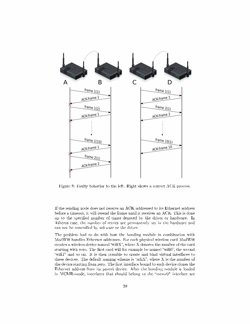
Figure 8: Faulty behavior to the left. Right shows a correct ACK-process.
If the sending node does not receive an ACK addressed to its Ethernet addressbefore a timeout, it will resend the frame until it receives an ACK. This is doneup to the speci�ed number of times denoted by the driver or hardware. InAtheros case, the number of retries are permanently set in the hardware andcan not be controlled by software or the driver.
The problem had to do with how the bonding module in combination withMadWi� handles Ethernet addresses. For each physical wireless card MadWi�creates a wireless device named �wi�X�, where X denotes the number of the cardstarting with zero. The �rst card will for example be named �wi�0�, the second�wi�1� and so on. It is then possible to create and bind virtual interfaces tothese devices. The default naming scheme is �athX�, where X is the number ofthe device starting from zero. The �rst interface bound to each device clones theEthernet address from its parent device. After the bonding module is loadedin MCMR-mode, interfaces that should belong to the �mcmr0" interface are
20

enslaved. Enslaving is the process of associating sub interfaces with the bondinginterface, i.e. letting the bond interface know which interfaces it is responsiblefor. The bonding module which needs an Ethernet address for the �mcmr0�device, clones the address from the �rst enslaved interface. Consecutive enslavedcards will then via wireless extension IOCTLs be assigned the same Ethernetaddress.
Figure 9: Enslaving
When a frame was sent out, the source address was automatically set by thesystem to the ethernet address of �mcmr0� and all of its slaves, not the perma-nent Ethernet address of the dynamic interface actually transmitting the frame.However, an Ethernet address set manually does not propagate correctly to thehardware and therefore the hardware does not listen to frame acknowledgmentsaddressed to this Ethernet address.
This caused each frame to be resent by the hardware until it gave up and pro-ceeded to the next frame. This severely reduced throughput. The chosen solu-tion to solve the problem consists of letting the bonding module thread, whichservices the channels, set the source address of each frame to the switchableinterface's permanent hardware address just before it handles over the respon-sibility of the frame to the driver, see Figure 10.
21

Figure 10: Faulty behavior to the left. Right shows a correct ACK-process.
3.2.2 User space application
The user space application is responsible for initiating and con�guring the bond-ing module. It is also the one managing channel selection for �xed interfacesand handling neighbor information by sending and processing received HELLO-messages. The application was implemented as a module in the existing Mesh-framework created by CRL Sweden5. It is also possible to convert it to a stan-dalone application.
5http://www.crlsweden.com/
22

The implementation is capable of handling an arbitrary number of bondinginterfaces (viz. mcmr0, mcmr1 and so on) each with an arbitrary number ofenslaved �xed and switchable interfaces.
During upstart the application reads a con�guration �le containing all the con-�gurable parameters needed to init the application and the bonding module.
Con�guration �le example:
#Virtual MCMR-interface
MCMRInterface = "mcmr0"
#Enslaved fixed interface
FixedInterface = "ath0"
#Enslaved switchable interface
DynamicInterface = "ath1"
#Interval beween outgoing HELLOs
HelloInterval = 5000
#Port to listen for HELLOs on
ListenPort = 55000
#When to classify a neighbour as old
NeighbourEntryExpire = 11000
#Time between checks for stale entries in the neighbour table
NeighbourExpireCheck = 3000
# Channels not to use
ExcludedChannels = 36,44,48,52,56,64,104,108,112
#Frequency range: A or G
FrequencyRange = A
The application then activates each interface in the bonding module and setsthem to the correct mode. This is done by IOCTL calls to the module. It alsoenables all channels for each card except the ones denoted by the parameter�ExcludedChannels�. In a network with few nodes it is bene�ciary to only use afew channels, because this minimizes the number of channels broadcasts mustleave on, hence lowering the number of required channel switches. It is importantthat all nodes in the network have the same set of active channels or networkpartitions could occur.
Even if it would be possible for the nodes to use the frequencies de�ned by both802.11a and 802.11g this is not allowed by the application due to the increasedswitching cost involved.
A �xed channel is chosen by random from the by hardware supported channelsfor each �xed interface and assigned via a regular wireless extension IOCTL.After initiation the application starts to send and listen for HELLO-messages.
HELLO-messages
Once during the speci�ed interval the node broadcasts a HELLO-message. Themessage will in other words be transmitted on all allowed channels. The purposeof this message is to inform neighbors about its presence and what channel or
23

if it has multiple �xed interfaces - channels, the neighbors must use to transmitdata to the node. The data consists of each cards permanent Ethernet addressand its currently used channel. If the node itself has received HELLO-messagesfrom other nodes it includes data about these one-hop neighbors. This data iscomprised of the nodes IP address and Ethernet addresses of each of the �xedinterfaces plus the associated channels. With this information it is possible forthe receiver to correctly calculate the channel usage in the two-hop neighbor-hood. The Ethernet address is needed by the receiver to identify if it alreadyknows about the other node as a one-hop or possibly two-hop neighbor.
The HELLO-message interval a�ects the networks mobility. In a static networkit can be su�cient to send out messages for example once every 30 secondsor even less. In a mobile network with nodes moving around plus leaving andentering the network frequently the interval must be decreased to not leaveinvalid entries in the nodes' neighbor tables.
Before each HELLO-message the node consult the channel usage list to check ifit is bene�ciary to change one of its �x channels. If one of the current channelsis used by more nodes than the node itself, it checks if there are any unusedchannels or a channel with a lower usage that would be bene�ciary to change to.If there is such a channel there is a 50% chance of the node actually changingchannel. This is to avoid a state where multiple nodes frequently switchesbetween channels.
Figure 11: Send HELLO-message
Neighbor- and channel management
After receiving a HELLO-message the information is analyzed. The sendingnode of the message is a one-hop neighbor to the receiver and can be reached
24

directly by the node. The neighbors Ethernet addresses and each correspondingchannel is recorded in the nodes neighbor table along with a last-seen timestamp. If the node already exists as a two-hop node, it is promoted to one-hop.Each one-hop tuple is then added to the bonding module via IOCTL as anunicast entry. The channels used is also added to the channel usage list. Thepurpose of this list is to record all channels used and their usage count in thetwo-hop neighborhood. If a node changes channel the usage of the old channelis decreased by one and the new channel's usage increased.
Figure 12: Receive HELLO-message
The nodes in the message data - containing the senders one-hop neighbors -are all possible two-hop neighbors to the receiving node, but they can also beone-hop neighbors. Each entry is compared to the entries in the neighbor table.If the node exists and is already known of as a one-hop neighbor the data isdisregarded and the last-seen time stamp is not updated. If the time stamp wasupdated, it could cause none existent nodes to be kept alive in the network astwo-hop. If the node exists as a two-hop neighbor the information is updated.If it does not exist, and the channels is supported, it is added as a two-hopneighbor. These neighbors are not added to the bonding module, they are onlyused for channel usage statistics. The channel usage list is updated accordingly.
Regular checks are done for stale entries in the neighbor table. If a one-hop or atwo-hop neighbor has not been heard of for the speci�ed time, it is classi�ed asstale and removed from the neighbor table. One-hop neighbors is also removedfrom the bonding module. In a highly mobile network the value �NeighborEn-tryExpire� must be low to not keep invalid nodes in the neighbor table.
25

3.2.3 MadWi� WLAN driver optimizations
The bonding module and user space application works with all hardware driverswith support for IBSS. However, due to the frequent channel switches the perfor-mance can su�er due to hardware and driver taking long time to switch betweenchannels.
Measurements showed that a recent development SVN version of MadWi� had aswitching time of about 8-9 ms measured from the time the driver got the IOCTLuntil the IOCTL returned. The stable 0.9.4 version showed better timings ofaround 5 ms.
MadWi� version Average switching time (seconds)0.9.4 0.004959SVN rev 3517 0.008580
The higher switching times for the newer SVN version is probably due to codeadditions added to comply with the IEEE 802.11h-2003 standard [20]. Thisstandard provides Dynamic Frequency Selection (DFS) which mean an accesspoint should avoid channels which is used by satellites and radars. Because ofthis and the fact that the version has proven to be stable on the Avila platform,the 0.9.4 version was chosen to be optimized.
MadWi� was studied to identify what happened from the moment the driver gotthe change channel IOCTL until the change was done. Each important functionwas timed and functions going down to the hardware via HAL were identi�ed.HAL is short for �Hardware Abstraction Layer� and provides an interface whichMadWi� must use to control the actual hardware. This is to make sure MadWi�does not change values in hardware registers which it is not supposed to change,e.g. use illicit frequencies or too high transmission powers.
When a call is made to change channel, MadWi� does the following importantsteps:
First it disables interrupts to avoid being interrupted by the device. Then itstops all outgoing transmissions and drains the current pending transmissionqueue by dropping all unsent queued packets by calling �ath_draintxq�. Afterthis �ath_stoprecv� is called. This function instructs the hardware to stoppacket reception and tells above layers to queue pending outgoing packets. Thenthe hardware is reset, this is where the actual frequency change occurs. Afterthe reset a few things such as transmission power limits, channel �ags and, ifit is a change between modes, hardware rate maps are updated. Then packettransmissions and reception are enabled. A few of these functions was possibleto optimize or completely remove to lower the total switching time.
Some example functions and their approximated execution time:
26

Function Exec (sec) Commentath_hal_intrset 0.000008 Disable/enable interruptsath_draintxq 0.000063 Disables packet transmission
and drain pending out-queueath_stoprecv 0.003025 Disables packet reception by
disabling PCU and DMA engineath_hal_reset 0.000650 Hardware resetath_update_txpow 0.000315 Update transmission power limits
after channel changeath_startrecv 0.000195 Start reception of packets
Two important functions are �ath_hal_reset� and �ath_startrecv�. The �rstfunction is a call to HAL resetting the hardware and doing the actual chan-nel change. All operations is out of MadWi�'s control. Hence, not possible tooptimize. The second function initiates reception bu�ers and the like to en-able packet reception after a reset. It consists mostly of calls to the HAL andtherefore not either possible to optimize without having access to the HAL-codeand hardware. Based on this, a hard theoretical minimum value with currenthardware and HAL is around 0.000845 seconds (0.845 ms).
The function responsible for over 0.003 seconds during a change is �ath_stoprecv�.This function disables packet reception by disabling Packet Control Unit (PCU)and the Direct Memory Access (DMA engine). After disabling DMA it sleepsfor 0.003 seconds to let a possibly present DMA-operation �nnish. This sleepwas removed during optimizations along with functions deemed unnecessary forthe operation of MCMR, for example all functions which updates channel �ags,transmission power limits and the hardware rate map when changing betweennodes. Also the state machine was eliminated. After optimizations the channelchange time was on average 0.000997 seconds.
A lot of the optimizations performed were MCMR-speci�c and broke normalbehavior of the driver. Therefore, it was made possible to turn on and o�optimizations when loading the MadWi� module.
Another optimization was to disable the 802.11 beacons on the interfaces. Inan ad-hoc network beacon frames are normally broadcasted to inform nodesin the vicinity about the nodes service set identi�er, supported rates and otherparameters. This information is needed to setup communication between nodes.Due to the characteristics of the MCMR setup, beacons are not needed and onlycause unnecessary overhead.
Pending out-queue
Any packets waiting to be transmitted in the drivers out-queue are droppedwhen a channel change is ordered. To enable the bonding module to querythe driver for the queues state, the existing function in MadWi� which returnswireless statistics was modi�ed. This function is called by a wireless extension
27

IOCTL and a variable - otherwise set by MadWi� to zero - was modi�ed toreturn the number of bytes left in the queue. This information makes it possiblefor the bonding module to calculate an expected transmission time and stallbefore issuing a channel change. Allowing packets left in the out-queue to betransmitted instead of discarded.
28

4 Results
This sections presents the results from the performance tests made with theintention to compare the usual single-channel, single-radio setup to MCMRunder fair conditions.
When running MCMR, each node is equipped with two interfaces operatingin 802.11a mode. The single interface setup is using the same hardware andthe identical settings. Channel 64, 100 and 120 was mainly used when testingto make sure the channels did not interfere with each other. The tra�c wasgenerated and measured using Iperf6 on standard desktop computers to not putany more load than necessary on the Avila Network Platforms.
To test the advantage of using multiple channels compared to a single channel,the �rst scenario consists of a total of four nodes. The four nodes are neighbors,i.e they all hear each other. Two of the nodes are responsible for transmissionof data and two acting as receivers. The two sending nodes simultaneouslygenerate tra�c to one receiving node each.
Simultaneously transmissions on the same frequency are bound to interfere, re-sulting in a decreased throughput. Hence, utilizing two non-interfering channelsshould increase throughput.
Figure 13: Scenario 1, one-hop, two channels scenario
The �rst test, Figure 13, con�rmed that two separate channels can be usedsimultaneously without any interference. Transferring data between two nodes,
6http://sourceforge.net/projects/iperf/
29

four nodes in total, using MCMR resulted in doubling the throughput, as shownin Figure 14.
Figure 14: Scenario 1, throughput
When only using one channel, all transmissions have to share the channel band-width. In this case the bandwidth is 30 Mbit/s, resulting in 15 Mbit/s oneach transmission. When increasing the number of simultaneously transmissionsbetween nodes in a single-channel neighborhood, the bandwidth will decreaseaccording to a simple formula:
throughput =maximumchannel bandwidth
number of transmissions
If instead using multiple channels, the throughput will be equal to the maximumchannel bandwidth as long as the number of available non-interfering channelsare equal or more than the number of simultaneously ongoing transmissions.That is, each transmission will be able to use a unique channel:
throughput =maximumchannel bandwidth
number of transmissionsnumber of used channels
The second scenario is a simple setup to test the end-to-end one way (halfduplex) throughput using one, two and three hops. Transmitting data betweensender and receiver using two nodes takes one hop, while four nodes enables athree hop scenario. Since data will only be sent in one direction, no channelswitching will be required other than when broadcasts are sent.
Figure 15: Scenario 2, multi-hop
30

This test showed that both single-channel, single-radio and MCMR reached thepractical limit of 33 Mbit/s over one hop. However, when sending data over twohops, MCMR was able to increase the throughput by 60%.
Figure 16: Scenario 2, performance
Even though MCMR uses di�erent channels, the throughput will decrease dueto high processor load on the nodes both receiving and transmitting data. Amore powerful platform would probably be able to increase throughput.
In a perfect setup where each node only has two neighbors and the distanceis enough to avoid two-hop interference, the single-channel single-radio will beable to keep the 15 Mbit/s over 3 hops and more. Performing fair tests onmore than two hops, however requires the ability to strictly control the rangeof each node or a very large testing site, which was not possible within thescope of this report. A few tests using a MCMR setup and the user spaceapplication iptables7 to block certain nodes from hearing each other was howeverperformed and showed that the throughput reached about 24 Mbit/s over 3 hops.This shows that the MCMR solution is capable of improving the bandwidthover multiple hops compared to a single-channel single-radio setup. Even ifthe measured 24 Mbit/s is signi�cantly higher than 15 Mbit/s obtained withthe single-channel single-radio setup, it is far from the 33 Mbit/s measured inprevious tests for MCMR over one-hop. The main reason for this is the increasedchannel switching required in the three-hop setup.
7http://www.net�lter.org/
31

5 Discussion
5.1 Implementation
Implementing the multi-channel multi-radio solution in practice was not withoutissues. Development of the user space application and the creation of the newbonding module mode were quite straight forward. The problems encounteredwere mostly quickly solved. A far greater problem was MadWi� and its numer-ous issues already present in the driver. Issues such as memory leaks which maynot be notable in a normal environment, but certainly noticeable when broughtto the extreme by the frequent channel switching.
The choice to implement a solution without network wide synchronization or acommon shared channel resulted in a solution requiring frequent channel switch-ing. An initial concern was that the switches would introduce an unacceptablelatency to the network. In early test builds without any modi�cations to theWLAN driver this was also the case. However, with an optimized driver theobtained test results show that it is possible to in practice yield an increase inthroughput while using a multi-channel multi-radio solution without introducingunacceptable delays due to channel switching.
5.1.1 Bonding driver
The central part of the implementation is the bonding driver mode. It is re-sponsible for the di�erent channel queues and the operation of the switchableinterfaces. The choice to utilize much of the already present features of thebonding driver was inspired by Kyasanur [4, 12] and has been successful. Itsaved a lot of development resources and have created a versatile solution easyto modify and extend. For example CRL Sweden has extended the MCMRmode to handle a network consisting of nodes with directional antennas - anetwork con�guration the original mode was not intended to handle. The cur-rent implementation only supports a total of two cards - one �xed and oneswitchable. Support for more cards, �xed and switchable, is possible to imple-ment without making extensive modi�cations. For example, to add support formore switchable interfaces a thread for each interface must be created and rulesfor how the threads are allowed to service the common packet-queues must beadded. By adding support for more cards it is possible to adjust the ratio of�xed and switchable interfaces. A node must have at least one of each type,but depending on the nodes role in the network it can be bene�cial to have forexample three of four cards to be �xed. This particular setup could be used ona gateway node which mostly receives incoming tra�c and does not have muchoutgoing.
One problem in multi channel networks is how to make sure local broadcastsreach all neighbors. To fully utilize multi channel support all nodes shoulduse frequencies which do not overlap or interfere. This means nodes can only
32

hear messages on the speci�c channel they are currently tuned to. To solvethis all broadcast messages are send out on all channels. This unfortunatelyintroduces both channel switching and data overhead. The switching overheadgrows with the number of channels available and it is therefore advantageousto disable channels in a network with few nodes or in a network where thenodes' coverage do not overlap. The current implementation lets the user spaceapplication enable the channels that should be used during start-up. Oncea channel is activated it is not possible to deactivate it during runtime. Anadvanced solution could be to implement dynamic enabling and disabling basedon the number of nodes in the network. Because local broadcasts must reachall nodes in the neighborhood to not introduce network partitions, all nodesmust have the same channels available. This means a dynamic con�guration ofavailable channels must be done by a distributed vote among all the nodes inthe network.
The bonding module allows for a lot of performance �ne-tuning. There area lot of di�erent parameters that can be tuned to optimize general networkperformance or to suit speci�c network- and tra�c characteristics. The mostimportant part of the bonding driver is the thread or threads servicing thepacket queues. The current implementation services the queues in order. Butit is possible to modify this behavior and use a more advanced queue strategy.For example is it possible to prioritize the queue with the oldest data or thequeue with the most data. Another parameter to optimize is how long a threadservices a speci�c queue. By modifying the minimum staying time for a threadon a queue it is possible to lower the amounts of channel switches and let theinterface spend more time servicing queues. The higher the value is, the fewerthe channel switches. However, a too high value might a�ect the latency in thenetwork negatively because data in other queues will have to wait longer beforethe thread can service them. A high minimum staying time is more bene�cialon a system where the time it takes to perform a channel switch is high. On asystem with low switching time it might not be bene�cial to stay and wait formore data and better to switch directly when the queue is empty.
Another parameter related to the minimum staying time is the maximum stayingtime on a channel. If a thread is only allowed to switch channel when thecurrent queue is empty, it can cause starvation of the other queues. By addinga maximum duration a thread can service a channel each time, the thread isforced to check the other queues and service them if necessary. A low valuewill increase the time spent switching but might also decrease the networkslatency. An advanced solution would be to dynamically modify the minimum-and maximum staying time based on the networks current tra�c characteristics.
Another implementation detail is how to handle the hidden terminal problem.In a dense network with many nodes switching channels this could potentiallybe a large problem degrading network throughput. The current implementationmakes it possible to statically assign a duration each node must wait aftera channel switch before trying to send data. In a dense network with manyactive nodes trying to transfer data the optimal waiting time approaches the
33

maximum transmission time of a maximum sized packet. In a not so densenetwork it is bene�cial to have a low waiting time due to the risk of multiplenodes transmitting simultaneously is decreased. Once again, an optimal solutionwould be a dynamic solution. For example it would be possible to calculate thewaiting time based on known one-hop neighbors. This calculation would not betime critical and therefore bene�cial to perform in the user space application.
During the process of solving the initial performance problems described in de-tail in chapter 3.2.1 the bonding driver and user space application were testedwith Intel based cards and the Intel PRO/Wireless 2200BG driver for Linux8.This driver behaves di�erent when creating interfaces compared to MadWi�.While MadWi� creates a �wi�X� card representing the physical device and thenbind virtual interfaces to these, e.g. �ath0�, the Intel driver directly creates an�ath0� interface. After some initial problems getting the Intel drivers to runcorrectly on the Avila platform they worked without complications in combina-tion with the bonding driver. Although no measurements were performed onchannel switching time, throughput were as expected over one-hop and broad-cast messages was correctly transmitted on all channels. This showed that theimplementation is compatible with di�erent hardware and drivers. The Inteldriver unfortunately uses a proprietary �rmware which makes it impossible tooptimize channel switching.
5.1.2 User space application
All non-time critical functions are placed at user space. Most of the featurescould also be integrated in the bonding module. This is however not recom-mended. Common programming practice is to place only the necessary featuresin kernel space, e.g. time critical and features needing access to system resourcessuch as network interfaces. Developing code at user space is also more conve-nient, e.g. memory management is easier and the program can crash withoutbringing down the whole system. The latter is often the consequence if a modulecrashes due to the module sharing the kernels code space [22].
The application keeps track of the neighboring nodes and updates the bondingdriver with information about which channels a one-hop neighbor can be reachedon. Each node spread information about its own channels and its known neigh-bors by regularly broadcasting HELLO-messages. These messages introduce anoverhead which grows with the number of neighbors and the lower the interval isset. The minimum size of a HELLO-message for a node with one �xed interfaceand no neighbors are 17 bytes. Then the size grows 11 bytes for each neighboradded with one �x channel. The size of the message header for each node is 6bytes and each channel, i.e. each �xed interface at the node, takes an additional5 bytes. This doesn't take much of the available bandwidth even if HELLOsare sent several times per second to suit a mobile network. The broadcast na-ture of HELLOs requires that they must be delivered on all available channels.
8http://ipw2200.sourceforge.net/
34

This means the total data that will have to be transmitted for each HELLOis: (size of HELLO) * ( number of channels ). The channel switching overheadmust also be taken into account. However, we believe the lack of a demandfor a network wide synchronization, which has been proven di�cult [16, 9] ora common dedicated channel outweigh the overhead introduced. It is possibleto minimize size of the HELLO-messages. For example by implementing a newmessage structure capable of compressing addresses. Another possibility is tocombine the messages with existing routing messages. This would lower thetotal number of broadcast messages in the network and hence lower switchingcost.
The information received from neighbors' HELLO-messages is not only used toget information about how to reach the neighbors, but also to gather informationabout the two-hop neighborhood. This information is used to calculate whichchannels to use for the nodes �x interfaces. Each node strives to minimize thetotal usage number for each channel. No investigation on algorithms choosingthe optimal channel was done. For example, if two channels shares the sameusage as well as has the lowest usage the node randomly choose which to use.This choice could be modi�ed and based for example on which neighbors thatare using the channels. Actual channel utilization could also be measured andused as a basis for the channel choice, e.g. prefer the one with lowest usage. Itwould also be possible to let the routing protocol choose channels. There are alot of proposed modi�cations to existing routing protocols, a few described inthe analysis. One bene�ts with letting the routing protocol choose channels isthat it has extended information about the network and can setup both routesand channels.
There are measurements in place to avoid too frequent channel switches on �xedinterfaces and to avoid a state in the network where several nodes constantlyswitches between channels. When a node decides it would be bene�cial tochange channel, a random function decides if to change channel or not. This isbased on a percentage, the current implementation uses 50% chance of changingchannel and has worked well in the test setup. This value could however needsome modi�cations in a real network to avoid channel hysteresis.
5.1.3 WLAN driver
MadWi� was the open source driver of choice. It supports a range of Atheroschip-sets often found on common and cheap wireless cards. It proved to be thesingle area responsible for most troubles during development. The �rst problemencountered had to do with frame acknowledgments when running in MCMR-mode and is described in more detail in the method. This was an issue notpresent in for example the Intel wireless driver. The current solution is workingand no bad side e�ects has been identi�ed. The issue could probably be solvedin the driver if it had direct access to the hardware and wasn't required tocommunicate via the hardware abstraction layer.
35

Later in the development and during testing other issues were encountered.Channel switching is normally something done �once in a while�. In a standardsetup the only time channel switching is somewhat frequent is when the cardperforms a scan. If not user triggered, scans are normally not performed veryoften. A background scan in MadWi� with the purpose of �nding a betterAP when in roaming mode will be done once every 5 minutes. WLAN driversand hardware are therefore normally not optimized to perform fast channelswitches. An unmodi�ed version of MadWi� takes from 5 ms up to about 10ms per channel switch. This duration is too long to perform well when channelswitches can occur up to a 100 times a second . Therefore MadWi� was modi�edto better support frequent channel switches. By identifying and removing stepsin the channel change process that is not necessary during MCMR-operation,it was possible to bring the delay down to about 1 ms. It is in theory possibleto lower this even further by removing more steps in the driver. However,MadWi�'s only method of telling the hardware to change channel is to requesta reset. Measurements shows that this reset takes about 0.650 ms with currenthardware. After the reset there are a few calls steps to setup the hardware.These add about 0.100-0.200 ms to the switch time. This shows that it wouldbe bene�cial to create hardware with faster channel switching support.
Working with MadWi� has not been trouble free. The driver consists of a lotof code, largely undocumented, which resulted in that the process of optimizingwere often trial-and-error. The �rst version optimized were the stable release0.9.4. During testing this version had large amounts of memory leaks causingnodes to crash or behave suboptimal. Changes made to the driver could not haveintroduced such behavior. Instead it is more likely that the frequent channelswitching made an existing problem much worse. A study of existing bug ticketsfor MadWi� showed that other users experienced problems. A lot of leaksseemed to have to do with the management of Linux network bu�ers and thedrivers node references to neighbors being lost during di�erent scenarios. Bytesting di�erent SVN versions of the driver the problem were alleviated but notfully removed.
The current implementation is based on a SVN revision 3226 from early 2008.Memory leaks still exists but mostly shows during high load on nodes whichperform frequent switching. Newer SVN versions were tested but these intro-duced problems with channel switching, for example not being able to switchwhile the card was in UP state.
The memory leaks has proved troublesome during testing and must be �xed ifthe setup would be used outside of a test environment. It is possible that thereversed engineered successor to MadWi�, ath5k might solve a lot of problemswhen it is ready for deployment. It is at the moment not an option due to beingearly in development and missing a key set of features.
All data queued by MadWi� but not yet transmitted on the current channelis purged when a channel switch is ordered. This has the possibility to causeunnecessary packet drops. The features added to let the bonding module stall
36

if there are data left proved to be not all that successful. If there are dataleft to be transmitted the bonding driver has the possibility to calculate anexpected transmission time and then stall before telling the driver to changechannel. However, due to these queues being in MadWi�, i.e. in software andnot the hardware, it is not possible for the bonding driver to do a blockable sleepwhile waiting for the data to be processed. A blockable sleep means that noother code, such as MadWi�, can be run on the processor. This would howeverhave been possible if the frames were queued in the hardware. Quite often thecalculated stall duration proved to be too small in relation to the minimumsleep interval provided by methods to yield the processor to other processes andtherefore not bene�cial. The minimum scheduling time for a process is 1 ji�e,which in Linux 2.6.19 with default settings converts to 10 milliseconds. Due tothis the current implementation of the bonding driver has the feature disabled.
5.2 Limitations
The chosen approach requires at least two wireless cards. There are other multichannel approaches which gain performance improvements by using one card,see chapter 2.3. However these often require modi�ed MAC protocol which wasnot an option.
The chosen approach also requires low channel switching times to provide ac-ceptable performance. If the driver has poor channel switch characteristics itmust be optimized. This is only possible with access to the drivers source code,something which is seldom provided. This limits the choice of WLAN driversand hence available hardware.
The current implementation also has limitations. For example the bondingdriver does not allow more than two cards in total. This support is howeveralready present in the user space application. The current implementation alsolacks for support single card nodes in the network. In a typical network setupMCMR nodes would form the high bandwidth backbone and single card nodeswould connect to a regular access point that in turn is connected to the MCMRnodes. It would however be possible to connect single card nodes directly to theMCMR network by modifying the user space application and bonding driver.If the �xed interface is capable of both receiving and sending tra�c and byenabling the �xed interface to send out beacons to alert single card nodes of itspresence, then single card nodes could connect to the �xed interface just like aregular access point.
5.3 Future
The solution/implementation was created to work on the Gateworks Avila 2348-2 Network Platform9 with support for only two WLAN cards and a 266MHz
9http://www.gateworks.com/products/avila/gw2348-2.php
37

CPU. Hence, more powerful platforms with more support could result in adi�erent approach. Gateworks top of the line network platform, the CambriaGW2358-410 supports four WLAN cards and runs a 667MHz CPU. If havingthe possibility to utilize four WLAN cards, three of the cards could for exampleadapt to the tra�c load and help out where ever necessary. Hence, switchingbetween sending and receiving data. Only one of these three cards would haveto be responsible for handling control data like HELLO-messages. This wouldallow the other cards to concentrate on processing data on one channel and notfrequently having to change each time the HELLO-messages are to be sent.
Besides the evolution in hardware, more wireless standards are developed. Oneof the most ground breaking is the IEEE 802.11n [26] standard which improvesthe wireless technology in both range and throughput. Improvements havebeen made in the physical layer as well as in the MAC layer compared to IEEE802.11a/b/g. These changes enable the theoretical throughput to increase from54 Mbit/s in 802.11a/b/g to 600 Mbit/s when applying 802.11n. Equip a Cam-bria Network Platform with four 802.11n WLAN cards and the possibilities - incase of performance - are endless.
Most important is however further optimizations to the bonding driver and thewireless drivers. Primarily a more dynamic queue handling with the ability toservice queues depending on di�erent conditions and variables.
10http://www.gateworks.com/products/cambria/gw2358-4.php
38

6 Conclusion
In this report, we have investigated di�erent approaches and the possibilitiesto implement multi-channel, multi-radio to increase performance in wirelessmulti-hop mesh networks. After reviewing a set of proposed solutions, a hybridmethod was chosen. This approach had the most advantages compared to itscompetitors, but was still not trivial to put into e�ect. The implementationin user-space was fairly straight forward as opposed to adding support in theoperating system and wireless drivers. Not only did it have to work, but opti-mizations had to be done to get a substantial increase in performance comparedto a ordinary single-channel, single-radio setup.
When creating a chain of nodes, each node has to be in range of two neighboringnodes - one on each side - for the chain to work. If the nodes uses only asingle channel, each intermediate node has to receive and transmit on the samechannel causing an interference that will halve the maximum throughput. Whenapplying MCMR, the intermediate node can make use of the advantages withnon interfering channels by using two di�erent channels simultaneously.
Consider a wireless network consisting of several nodes - utilizing a single channel- in for example a wide city network. To avoid too much interference in such anenvironment, the nodes placement would have to be well planned. If the nodesinstead deployed MCMR, interference wouldn't be such a big problem due tothe implemented intelligence. Furthermore, in a close environment where allnodes are in range of each other, a single-channel, single-radio setup will onlybe able to reach a total of 33 Mbit/s split between the nodes transmitting datadue to interference. The more nodes involved, the more useful MCMR is andexactly by how much the performance would increase can only be answered byperforming more extensive testing.
Our implementation has shown to be suitable in di�erent scenarios and withhardware prices decreasing, also a cost e�ective solution to enhance performancein wireless networks.
The next step would be to use more powerful hardware with support for moreWLAN cards and abandon the MadWi� driver in pro�t for the new and con-stantly improved ath5k driver 11. Also switch to IEEE 802.11n which is sup-ported by ath9k 12. Both ath5k and ath9k are included in the Linux kernel asfrom version 2.6.25. Also, further investigate optimizations to the drivers.
11http://linuxwireless.org/en/users/Drivers/ath5k12http://linuxwireless.org/en/users/Drivers/ath9k
39

References
[1] D. Valerio, F. Ricciato and P. Fuxjaeger, �On the feasibility of IEEE 802.11multi-channel multi-hop mesh networks�, COMCOM 3857, 2008.
[2] �IEEE 802.11,2007 IEEE Standard for Information technology-Telecommunications and information exchange between systems-Local andmetropolitan area networks-Speci�c requirements - Part 11: Wireless LANMedium Access Control (MAC) and Physical Layer (PHY) Speci�cations�,2007.
[3] P. Kyasanur and N. H. Vaidya, �Routing and Link-layer Protocols for Multi-Channel Multi-Interface Ad Hoc Wireless Networks�, SIGMOBILE MobileComputing and Communications Review, 10(1):31�43, 2006.
[4] P. Kyasanur and N. H. Vaidya, �Routing and Interface Assignment in Multi-Channel Multi-Interface Wireless Networks�, in WCNC, 2005.
[5] J. So and N. H. Vaidya, �Multi-channel MAC for Ad Hoc Networks: Han-dling Multi-Channel Hidden Terminals using a Single Transceiver�, in Mo-bihoc, 2004.
[6] A. A. Pirzada, M. Portmann and J. Indulska, �Hybrid Mesh Ad-hoc On-demand Distance Vector Routing Protocol �. In Proceedings of the Thirti-eth Australasian Computer Science Conference (ACSC'07), volume Vol 29,pages 49�58, 2007.
[7] A. A. Pirzada, M. Portmann and J. Indulska, �Evaluation of Multi-RadioExtensions to AODV for Wireless Mesh Networks�, MobiWac '06, 2006.
[8] C-Y. Li, A-K. Jeng and R-H Jan, �A MAC Protocol for Multi-ChannelMulti-Interface Wireless Mesh Network using Hybrid Channel AssignmentScheme�, Journal of Information Science and Engineering 23, 1041-1055,2007.
[9] R. Maheshwari, H. Gupta and S. R. Das, �Multichannel MAC Protocolsfor Wireless Networks�, SECON '06, 2006.
[10] P. J. T. Clausen. RFC 3626: �Optimized Link State Routing Protocol(OLSR)�, Oct 2003.
[11] D. B. Johnson, D. A. Maltz and Y.-C. Hu, �The Dynamic Source RoutingProtocol for Mobile Ad Hoc Networks (DSR)�, Ietf Manet Working Group(Draft 10), 2004.
[12] P. Kyasanur, J. So, C. Chereddi and N. H. Vaydia, �A Multichannel MeshNetworks: Challenges and Protocols�, IEEE Wireless Communications,2006.
40

[13] R. Draves, J. Padhye and B. Zill, �Routing Area in Multi-Radio, Multi-HopWireless Mesh Networks�, ACM Mobicom, 2004.
[14] R. de C. Paschoalino and E. R. M. Madeira, �A Scalable Link QualityRouting Protocol for Multi- radio Wireless Mesh Networks �, ICCCN 2007,2007.
[15] C. Perkins, E. M. Royer and S. Das, �Ad hoc On-Demand Distance Vector(AODV) Routing�, IETF RFC 3561, 2003.
[16] H-S. W. So, G. Nguyen and J. Walrand, �Practical Synchronization Tech-niques for Multi-Channel MAC�, MobiCom '06, 2006.
[17] M. X. Gong and S. F. Midki�, �Distributed Channel Assignment Protocols:A Cross/Layer Approach�, WCNC 2005, 2005.
[18] J. Yoo and C. Kim,�On the Hidden Terminal Problem in Multi-rate AdHoc Wireless Network�, ICOIN 2005, 2005.
[19] Linux Ethernet Bonding Driver HOWTO,http://www.mjmwired.net/kernel/Documentation/networking/bonding.txt,2009-09-25.
[20] C-Y. Li, A-K. Jeng and R-H Jan, �A MAC Protocol for Multi-ChannelMulti-Interface Wireless Mesh Network using Hybrid Channel AssignmentScheme�, Journal of Information Science and Engineering 23, 1041-1055,2007.
[21] IEEE 802.11h, http://standards.ieee.org/getieee802/download/802.11h-2003.pdf, 2009-09-24.
[22] The Linux Kernel Module Programming Guide,http://www.tldp.org/LDP/lkmpg/2.6/html/x427.html, 2009-09-24.
[23] International Standard ISO/IEC 7498-1:1994, �Information technology -Open Systems Interconnection - Basic Reference Model: The Basic Model�,Second edition 1994-11-15, Corrected and reprinted 1996-06-15.
[24] Douglas E. Comer, �Interworking with TCP/IP. Vol 1: Principles, Proto-cols, and Architectures�, Fourth Edition, 2000.
[25] Post- och telestyrelsens allmänna råd (PTSFS2005:4) om den svenska frekvensplanen,http://www.pts.se/upload/Documents/SE/frekvensplanen2005_4.PDF,2009-09-24.
[26] IEEE 802.11n, http://standards.ieee.org/prod-serv/80211n.html, 2009-09-24.
41

Nomenclature
802.11 A set of standards for wireless local
area networks
ad-hoc See IBSS
ARP Address Resolution Protocol - translates
an ip address to a hardware address
ATIM Announcement Traffic Indication Message -
announce that there are buffered frames
to be sent
CPU Central Processing Unit
DCF Distributed Coordination Function
IBSS Independent Basic Service Set - A
peer-to-peer wireless LAN configuration
part of the IEEE 802.11 standard.
IEEE Institute of Electrical and Electronics
Engineers - http://www.ieee.org
IOCTLs Input/output control - allows user-space
to communicate with drivers and kernel
kernel Central component of the operating system
MAC layer Media Access Control - A sublayer of the
Data Link layer (OSI model)
Mini-PCI Small formfactor extension cards for the
PCI bus
multi-channel Using more than one wireless channel
simultaneously
multi-radio Utilizing multiple WLAN cards on a single
node
NAV Network Allocation Vector - a mechanism
to avoid contention
Open Source Software under licenses which enables
users to modify the source code
OSI model Open Systems Interconnection Reference
Model
PCI Peripheral Component Interconnect - A
cumputer bus for hardware devices
42

rendezvous For example all nodes in the network
tunes to a predetermined channel at the
same time
WLAN Wireless Local Area Network
43

Appendix A
User space daemon
/** * Reads user config and sets up sub interfaces * for fixed and dynamic interfaces. */module_configure{
READ user configCONFIGURE_INTERFACE( interface, MCMR_FIXED )CONFIGURE_INTERFACE( interface, MCMR_DYNAMIC )SET Listen_PortSET Hello_IntervalSET Neighbour_Entry_ExpireSET Neighbour_Expire_CheckSET Frequency_RangeSETUP Enabled channels
}
/** * Initiates sockets and interfaces. * Starts function mcmr_hello_send for transmitting hello messages * and mcmr_input_poll_sockets for receiving. * Also starts remove_expired_neighbour to check and remove old neighbour entries. * */module_start{
IOCTL clear kernel registry for MCMR interfaceIOCTL open socket to bonding moduleREAD module configure parameters
FOR EACH MCMR interfaceSETUP MCMR interface specific dataINIT Listen_PortINIT Hello_IntervalCONFIGURE Neighbour_Entry_ExpireCONFIGURE Neighbour_Expire_Check
FOR EACH slave interfaceSETUP interface dataIOCTL enslave interface
IF fixed interface THENIOCTL enable fixed interfaceSELECT fixed interface channel randomlyIOCTL set channel
ELSE IF dynamic interface THENIOCTL enable dynamic interface
END IFEND FOR
END FOR
TIMER_REGISTER( Hello_Interval, mcmr_hello_send )TIMER_REGISTER( Interval, mcmr_input_poll_sockets )
FOR EACH MCMR interfaceTIMER_REGISTER( Neighbuor_Expire_Check, remove_expired_neighbours )
END FOR}
/** * Prepare and broadcast HELLO messages * */mcmr_hello_send{
INIT outgoing message
FOR each interface

IF fixed interface THENADD (permanent hardware address, current channel) to message
END IFEND FOR
FOR EACH known neighbourIF one-hop neighbour THEN
ADD (neighbour MAC address, neighbour channel) to messageEND IF
END FOR
SETUP MCMR-headerSETUP UDP-headerCALL NET_WRITE_SOCKET( message, broadcast-addr )CALL manage_fixed_channel
}
/** * Reads socket and checks if the message is a valid HELLO message. * Collects one- and two-hop neighbour information. */mcmr_input_poll_sockets{
CALL NET_READ_SOCKETCHECK for valid ip- and udp-header in message
IF message is a HELLO message && is valid THEN
IF sender of the HELLO has at least one valid channel THENIF neighbour already exist in neighbour list THEN
UPDATE neighbour last seeen timestampELSE
ADD neighbour to neighbour list, marked as one-hop neighbourIOCTL add neighbour to kernel modules registry
END IFEND IF
FOR EACH neighbour node included in HELLO messageIF two-hop neighbour has at least one valid channel THEN
ADD neighbour to neighbour list, marked as two-hop neighbourEND IF
END FOR
END IF}
/** * Removes old entries in the neighbourtable * */remove_expired_neighbours{
GET timestampFOR EACH interface
FOR EACH neighbourIF time difference between timestamp and last received HELLO > max expiry time THEN
REMOVE neighbour from neighbour listIOCTL remove neighbour from kernel module registry
END IFEND FOR
END FOR}
/** * Gets the number of neighbours using the channel the interface is currently tuned to. * Checks if there is a channel with less usage. * */manage_fixed_channel{
SET least_used_channel to current channel
FOR EACH enabled channelIF neighbours using the channel < neighbours using the least_used_channel THEN

UPDATE least_used_channelEND IF
END FOR
GENERATE random number between 0 and 10IF random number < 5 THEN
IOCTL set fixed channel to least_used_channelEND IF
}
Kernel module/** * Initiates the MCMR device. * This must be done before any interface * is enslaved. **/mcmr_init_bond_interface{
SET device nameCREATE proc directoryCREATE sysfsSETUP wireless handlersSETUP ioctl handlersINIT neighbour registry as emptyINIT packet queuesSTART MCMR workerSETUP xmit function pointerCALL register_netdevice
}
/** * Binds an interface to the MCMR device and * assigns default settings. **/mcmr_enslave_device{
STORE device's current flagsSTORE permanent MAC address
IF first device to be enslavedCOPY MAC address from slave to MCMR interface
ELSEASSIGN slave the same MAC as the MCMR interface
END IF
SET default MCMR flagsSET device inactive
}
/** * Set the mode of a previously enslaved interface * to fixed. **/mcmr_enable_fixed_interface{
SET mode fixedSET outgoing traffic disabledSET device as active
}
/** * Set the mode of a previously enslaved interface * to dynamic. **/mcmr_enable_dynamic_interface{
SET mode dynamicSET outgoing traffic enabled
FOR each enabled channelIF current frequency is supported by hardware THEN
INIT outgoing channel queueELSE
RETURN errorEND IF

END FOR
SET device as active}
/** * Called by the userspace daemon to * register neighbours received from HELLO * messages. Input parameters is the * neighbour's destination MAC and frequency. **/mcmr_io_add_unicast{
IF frequency corresponds to a packet queue THENADD neighbour tuple to registry [MAC, FREQ]
END IF}
/** * Called by the userspace daemon to * remove neighbours. **/mcmr_io_remove_unicast{
IF neighbour tuple exists THENREMOVE from registry
END IF}
/** * Queueing of packages in the packet queues. * Broadcasts and unicasts are handled differently. * * Broadcasts are copied to all packet queues and * for unicasts a neighbour lookup is performed to * find out which channel the packet should be * queued in. **/mcmr_enqueue_skb{
IF outgoing packet is broadcast THENFOR each channel queue
IF packet not a HELLO message AND no known neighbour on channelCONTINUE to next channel queue
END IF
IF queued bytes in queue + skb length > maximum queued bytes THENCONTINUE to next channel queue
END IF
COPY skbCALL mcmr_worker_enqueue(skb)
END FORELSE
Lookup neighbour information in the MCMR registryIF neighbour not found THEN
RETURN NET_XMIT_DROPEND IF
IF queued bytes in queue + skb length > maximum queued bytes THENRETURN NET_XMIT_DROP
END IF
CALL mcmr_worker_xmit(skb)END IF
UPDATE queue counters and statistics
RETURN NET_XMIT_SUCCESS;}
/** * Check if it is possible to transmit att packet directly. * If not, it is queued and later sent by the worker thread. **/mcmr_worker_enqueue{

IF hardware tuned to outgoing channel && all queues are empty THENSET source address in eth header to the cards permanent MAC addressCALL send function in the MadWiFi driver directly and handover the skb
ELSEQUEUE skb in the given queueWAKE UP worker if it's sleeping
END IF
UPDATE queue counters and statistics}
/** * Worker Thread: * The thread is responsible for servicing * each packet queue. If a queue has packets * the hardware is tuned to the corresponding * frequency and the packet is handed over to * MadWiFi for transmission. **/mcmr_worker_thread{
WHILE worker running
IF packets queued THENCALL SCHEDULE (interruptible timeout)
END IF
FOR each packet queue
IF queue is empty THENCONTINUE to the next queue
END IF
IF wireless card not tuned to the corresponding frequency THENREPEAT
IF hardware still have frames to send THENCALL SCHEDULE (interruptible timeout)
ELSECALL the hardware frequency tune function in MadWiFi
END IFUNTIL hardware tuned to the frequency
END IF
IF avoid hidden terminal is enabled THENSLEEP (uninterruptible) for the configured duration
END IF
START timer tracking how long the specific queue has been serviced
WHILE queue contains packetsDEQUEUE SKB from queueSET source address in eth header to the cards permanent MAC addressCALL send function in the MadWiFi driver and handover the SKBUPDATE queue information
IF another queue has packets AND current queue serviced for atleast the maximum specified duration THEN
BREAK to check the next channelEND IF
END WHILEEND FOR
END WHILEclean upKILL THREAD
}

Appendix B
Flow chart – MCMR worker threadstart
worker->die == 0kill
queued_packets_total == 0?
schedule interruptible timeout
YES
NO
for_each(channel queues)
specific queue empty?
currently tuned to the freqassociated with the queue?
issue freq switch
dequeue skb from queue
queue empty?
send skb
update stats
max stay exceeded current queue?
queued packets in this queue!=
total queued packets
YES
NO
NO
NO
YES
NO
NO
YES
Receive wake-up
YES
YES
NO
last queue?
YES
NO