GAPS GAPS –– Dark matter search Dark matter search using ...
Multi-Channel Direct Detection of Light Dark Matter: Target Comparison
Sinead M. Griffin,1, 2 Katherine Inzani,1, 2 Tanner Trickle,3, 4 Zhengkang Zhang,3, 4 and Kathryn M. Zurek5
1Materials Sciences Division, Lawrence Berkeley National Laboratory, Berkeley, CA 94720, USA2Molecular Foundry, Lawrence Berkeley National Laboratory, Berkeley, CA 94720, USA
3Department of Physics, University of California, Berkeley, CA 94720, USA4Theoretical Physics Group, Lawrence Berkeley National Laboratory, Berkeley, CA 94720, USA
5Walter Burke Institute for Theoretical Physics, California Institute of Technology, Pasadena, CA 91125,USA
Direct detection experiments for light dark matter are making enormous leaps in reaching pre-viously unexplored model space. Several recent proposals rely on collective excitations, where theexperimental sensitivity is highly dependent on detailed properties of the target material, well be-yond just nucleus mass numbers as in conventional searches. It is thus important to optimize thetarget choice when considering which experiment to build. We carry out a comparative study of tar-get materials across several detection channels, focusing on electron transitions and single (acousticor optical) phonon excitations in crystals, as well as the traditional nuclear recoils. We comparematerials currently in use in nuclear recoil experiments (Si, Ge, NaI, CsI, CaWO4), a few whichhave been proposed for light dark matter experiments (GaAs, Al2O3, diamond), as well as 16 otherpromising polar crystals across all detection channels. We find that target- and dark matter model-dependent reach is largely determined by a small number of material parameters: speed of sound,electronic band gap, mass number, Born effective charge, high frequency dielectric constant, and op-tical phonon energies. We showcase, for each of the two benchmark models, an exemplary materialwhich has a better reach than in any currently proposed experiment.
I. INTRODUCTION
Direct detection experiments have traditionally fo-cused on dark matter (DM) with mass near the weakscale. Cosmologically, however, thermal particle DM mayinhabit a much broader mass range between a keV and10 TeV. Recent years have seen bold advances in the ef-forts to probe DM in the range below 10 GeV, whichwas less explored previously. Here, despite the existenceof well-motivated candidates – including MeV dark mat-ter [1–3], WIMPless miracle DM [4], GeV hidden sec-tor dark matter [5–7], asymmetric DM [8, 9], freeze-inDM [10], Strongly Interacting Massive Particles [11], andmany others – conventional detection techniques basedon nuclear recoils lose sensitivity as the energy deposi-tion falls below detector thresholds. This has motivatedan extensive exploration of novel detection channels usinga variety of target systems. These include electron tran-sitions in atoms and semiconductors [12–25], supercon-ductors [26–28], Dirac materials [29–31], via the Migdaleffect [32–36], molecular dissociation or excitation [37–39], multi-excitation production in superfluid helium [40–43], defect production [44, 45], single phonon [46, 47] andmagnon [48] excitations in crystals (see also Refs. [49–56]for other recent proposals).
As new experiments are being planned and detectiontechnologies are being discussed and improved, it is im-portant to identify the most promising targets in orderto prioritize the experimental program. There are twoquestions in this respect: (i) what types of excitationscan be utilized as efficient detection paths with currentand developing technologies, and (ii) what materials havethe strongest response to DM scattering?
It is the purpose of this paper to initiate a discussionon these questions, and provide theory input to the op-
timization of experimental strategy. We consider severalcomplementary detection channels:
• nuclear recoils, sensitive to the heaviest DMmasses, down to O(100 MeV) at best;
• electron transitions across band gaps in crystals,covering DM masses down to O(100 keV);
• single phonon excitations in crystals, reaching thelightest DM masses, down to O(keV).
The last two detection channels rely on collective prop-erties of the target, which makes calculating the DMmodel reach more involved than the standard nuclear re-coil calculation. While nuclear recoil was proposed longago [57, 58], electron transitions in semiconductors (pro-posed in Refs. [12, 13, 16]) and phonon production fromsub-MeV DM in crystals (put forth in Refs. [19, 46, 47])have a much shorter history. Now that all these ideas areavailable, we hope to find materials which have a strongresponse in all channels, in order to cover a broad rangeof DM masses.
We begin in Sec. II with a brief review of each de-tection channel. A common framework to calculate thereach via all three channels is presented in a compan-ion paper [59], which makes it clear that the detectionrate factorizes into the particle-level scattering matrixelement squared and a material specific dynamic struc-ture factor that captures the target response. Here wesummarize the main results of Ref. [59]. Our goal is tofind materials with strong responses (a large dynamicstructure factor) in each channel over the kinematicallyallowed mass region.
Toward this goal, in Secs. III and IV, we carry out adetailed comparison of target materials, focusing on twobenchmark DM scenarios to illustrate how to optimize
arX
iv:1
910.
1071
6v3
[he
p-ph
] 1
9 O
ct 2
021

2
Target Eg [eV] cLAs [10−5] Aj Z∗
ε∞ ωO [meV] Q [10−7]
Si 1.11 2.84 28.1 - - 62.3 -
Ge 0.67 1.61 72.6 - - 34.8 -
NaI 5.8 0.90 23.0, 127 1.20 3.27 12.4 - 20.0 23
CsI 6.14 0.46 133, 127 1.22 2.70 6.9 - 10.0 12
CaWO4 5.2 1.42 40, 184, 16 2.84, 4.67 3.84 8.48 - 106 45
GaAs 1.42 1.57 69.7, 74.9 2.27 10.9 31.8 - 34.9 2.4
Al2O3 8.8 3.51 27.0, 16.0 2.97 3.26 35.6 - 104 130
Diamond 5.47∗ 5.98 12.0 - - 161 -
SiO2 9.2 5.76 28.1, 16.0 3.38 2.41 13.7 - 149 200
PbTe 0.19∗ 1.17 207, 128 5.69 26.3 3.91 - 13.5 1.3
InSb 0.24∗ 1.13 115, 122 2.40 23.7 20.5 - 21.5 0.34
AlN 6.20 5.70 27.0, 14.0 2.57 4.54 29.4 - 109 78
CaF2 11.81 2.15 40, 19.0 2.36 2.26 28.4 - 55.6 130
GaN 3.43∗ 4.17 69.7, 14.0 2.74 6.10 16.7 - 88.9 23
GaSb 0.720 1.32 69.7, 122 1.92 21.6 26.4 - 27.3 0.33
LiF 14.2 2.17 6.9, 19.0 1.05 2.02 33.5 - 77.2 270
MgF2 12.4 2.43 24.3, 19.0 2.00 1.97 12.1 - 73.7 130
MgO 7.83 3.11 24.3, 16.0 1.97 3.38 46.3 - 82.6 110
NaCl 8.75 1.19 23.0, 35.5 1.09 2.44 19.1 - 30.6 80
NaF 11.5 1.78 23.0, 19.0 0.98 1.78 29.6 - 49.9 140
PbS 0.29∗ 1.41 207, 32.1 4.45 15.0 7.27 - 26.9 4.9
PbSe 0.17∗ 1.27 207, 79.0 4.86 19.5 4.86 - 17.1 2.2
ZnO 3.3 4.18 65.4, 16.0 2.17 6.13 11.1 - 63.4 19
ZnS 3.80∗ 1.53 65.4, 32.1 2.03 5.91 32.8 - 41.0 14
Table I. Target materials studied in this work and their key parameters. The four blocks contain materials currently in usein nuclear recoil experiments, those considered for proposed near-future experiments, those with superior properties for somespecific DM models discussed in this paper, and the remaining ones in alphabetical order, respectively. Sensitivity of electrontransitions relies heavily on the band gap Eg, for which experimental values are shown (those with asterisks are measured at lowtemperature). Nuclear recoils and acoustic phonon excitations in the nucleon-coupling benchmark model are largely determinedby the speed of sound of longitudinal acoustic phonons cLA
s and atomic mass numbers Aj . For optical phonon excitations in the
light dark photon mediated model, relevant parameters are the Born effective charges Z∗, high-frequency dielectric constant
ε∞, optical phonon energies ωO as well as Aj , all of which combine into a quality factor Q, defined in Eq. (27), which determinesthe reach at high mass. Barred quantities are properly averaged values; see Appendix A 3 for details.
target choice for the best sensitivity. Our study covers atotal of 24 crystal materials, whose key properties thatdetermine sensitivity to DM scattering are summarizedin Table I. Six of the targets we consider are alreadyused in existing nuclear recoil experiments, including Si(DAMIC [60, 61], SENSEI [62], SuperCDMS [63–68]),Ge (SuperCDMS [63–68]), NaI (DAMA/LIBRA [69],KIMS [70], ANAIS [71], SABRE [72], DM-Ice [73]),CsI (KIMS [74]), Al2O3 (CRESST-I [75]), CaWO4
(CRESST-II-III [76, 77]), but their responses over allchannels have not been studied. Two other targets –GaAs and diamond – have been proposed for near-futureexperiments. We then choose a representative sample ofwell-known polar semiconductors comprising 16 materi-
als. Our work utilizes state-of-the-art density functionaltheory (DFT) calculations of material properties. Tech-nical aspects of these calculations are discussed in Ap-pendix A, where we also present our calculated electronband structures and phonon dispersions for the targetmaterials. In the main text, we will highlight a sub-set of these materials, chosen according to those cur-rently (previously) in use in direct detection (Si, Ge, CsI,CaWO4, (Al2O3)), as well as one or two new materialswhich demonstrate particularly strong sensitivity to eachbenchmark model. In particular, for the dark photonmediator, we highlight SiO2 and InSb. Results for thematerials not presented in the main text can be found inAppendix B, along with other parameters assumed when

3
calculating the reach.
II. DETECTION CHANNELS
We begin by briefly reviewing the detection channels,which are discussed thoroughly in our companion pa-per [59]. Generally, for a DM particle χ, the event rateper unit target mass is given by
R =1
ρT
ρχmχ
∫d3v fχ(v) Γ(v), (1)
where ρT is the target mass density, ρχ is the local DMenergy density, mχ is the DM mass, and fχ(v) is theincoming DM’s velocity distribution in the target restframe. The event rate Γ(v) for an incoming DM particlewith velocity v is usually normalized against a referencecross section, defined from the particle-level scatteringmatrix elementM (in the nonrelativistic normalization)evaluated at a reference momentum transfer q0. Here weadopt the following definitions,
σn ≡µ2χn
π|Mχn(q0)|2q0=mχv0 , (2)
σe ≡µ2χe
π|Mχe(q0)|2q0=αme , (3)
for DM-nucleon and DM-electron interactions, respec-tively, where µχn, µχe are the reduced masses, and v0is the dispersion of the DM’s velocity distribution. Theycoincide with the total particle-level scattering cross sec-tions in the case of a heavy mediator. As we show inRef. [59], for spin-independent (SI) scattering off a tar-get material via tree-level exchange of a mediator, thematrix element factorizes into a DM component that isuniversal, and a target response component captured bya dynamic structure factor S(q, ω) that is target and ex-citation specific, such that
Γ(v) =πσ
µ2
∫d3q
(2π)3F2
med(q)S(q, ωq
). (4)
Here σ, µ represent either σn, µχn or σe, µχe, q is themomentum transfer from the DM to the target, and
ωq =1
2mχv
2 − (mχv − q)2
2mχ= q · v − q2
2mχ(5)
is the corresponding energy deposition. The mediatorform factor is given by1
Fmed(q) =
1 (heavy mediator) ,
(q0/q)2
(light mediator) .(6)
1When present, in-medium screening effects are incorporated in thedynamic structure factor S(q, ω) instead of the mediator form fac-tor Fmed(q).
The dynamic structure factor, which captures the tar-get’s response to a general energy-momentum transferω, q, is given by
S(q, ω) ≡ 1
V
∑f
∣∣〈f |FT (q)|i〉∣∣2 2π δ
(Ef − Ei − ω
), (7)
where V is the total volume, |i〉, |f〉 are the initial andfinal states of the target system, and FT is the quantummechanical operator acting on the target Hilbert spacethat the DM couples to.
For an isotropic target, the dynamic structure factordepends only on the magnitude but not the direction of q,so the velocity integral can be evaluated independently,giving
η(vmin) ≡∫d3v
fχ(v)
vΘ(v − vmin) , (8)
vmin =q
2mχ+
∆E
q, (9)
for which analytic expressions can be obtained assuminga boosted truncated Maxwell-Boltzmann (MB) distribu-tion. On the other hand, for the more general case ofanisotropic target response, the dynamic structure fac-tor depends on the direction of q, and we can utilize thedelta function in Eq. (7) to evaluate the velocity integralfirst, giving
g(q, ω) ≡∫d3vfχ(v) 2π δ(ω − ωq), (10)
which can be computed analytically for the usually as-sumed boosted truncated MB distribution.
In the following subsections, we consider each detectionchannel in turn, summarizing the formalism presented inRef. [59] on the dynamic structure factors and detectionrates, building on the discussion in previous works (par-ticularly [16, 47, 78]).
A. Nuclear Recoils
For each nucleus species,
S(q, ω
)= 2π
ρTmN
f2Nf2n
F 2N (q) δ
(q2
2mN− ω
), (11)
where mN is the nucleus mass, fn, fp and fN = fpZ +fn(A − Z) are the DM-neutron, DM-proton and DM-nucleus couplings respectively, and FN (q) is the Helmform factor
FN (q) =3 j1(qrn)
qrne−(qs)
2/2 , (12)
rn ' 1.14A1/3n fm , s ' 0.9 fm , (13)

4
which approaches 1 in the q → 0 limit. The differentialrate with respect to energy deposition, generalized to thecase of multiple nucleus species, is
dR
dω=
ρχmχ
σn2µ2
χn
1∑N AN[∑
N
ANf2Nf2n
F 2N F2
med η(vmin)
]q2=2mNω
, (14)
where vmin = q2µχN
.
The conventional nuclear recoil calculation is validwhen each nucleus can be considered independent of theother nuclei. In a crystal target, this is true if the scat-tering happens at a timescale 1/ω much shorter thanthe inverse phonon frequencies 1/ωph, i.e. if the energydeposition ω ωph ∼ O(100 meV), or equivalently,q √mNωph (note that this momentum cutoff is essen-tially the inverse of the spatial extent of nucleus wave-functions in a harmonic potential). For lower energy de-positions, the scattering event proceeds by direct produc-tion of (single or multiple) phonons. We discuss singlephonon excitations in Sec. II C. We will see that singlephonon excitation rates are suppressed by the Debye-Waller factor for q &
√mNωph, which shows the comple-
mentarity between the two channels.
B. Electron Transitions
In solids, electrons form band structures with energyeigenstates labeled by a band index i and a wave vectork within the first Brillouin zone (1BZ). In an insulatoror semiconductor, all electrons occupy the valence bandsat low temperatures, and can be excited across the bandgap to conduction bands. The dynamic structure factorencapsulates all such transitions from i1,k1 to i2,k2:
S(q, ω
)= 2
∑i1,i2
∫1BZ
d3k1d3k2
(2π)62π δ
(Ei2,k2
− Ei1,k1− ω
)×∑G
(2π)3δ3(k2 − k1 +G− q)∣∣f[i1k1,i2k2,G]
∣∣2,(15)
up to screening effects. Here G = n1b1 + n2b2 + n3b3,with n1, n2, n3 ∈ Z and b1,2,3 are reciprocal primitivevectors. The crystal form factor is defined by
f[i1k1,i2k2,G] ≡∑
G1,G2
δG2−G1,G
u∗i2(k2 +G2
)ui1(k1 +G1
), (16)
where ui(k+G) are Bloch wavefunction coefficients com-puted from DFT (see Appendix A 1). We neglect possi-ble spin dependence of the electron band structures, andsimply sum over contributions from the degenerate spin
states. The total rate is given by
R =2
ρT
ρχmχ
πσeµ2χe
∑i1,i2
∫1BZ
d3k1d3k2
(2π)6∑G
g(q, ω)F2med(q)
∣∣f[i1k1,i2k2,G]
∣∣2 , (17)
where q = k2 − k1 + G and ω = Ei2,k2 − Ei1,k1 areassumed. Note that unlike in nuclear recoils, the dy-namic structure factor for electron transitions is generallynot isotropic in q for all energy-momentum depositions.When anisotropies are significant, the rate cannot be ex-pressed in terms of η(vmin), and the g function in Eq. (10)should be used instead. The physical implication is thatthe rate depends on the direction of the DM wind and ex-hibits daily modulation. An example of this is discussedin Ref. [59].
C. Single Phonon Excitations
Phonons are quanta of lattice vibrations in crystals.For a three-dimensional crystal with n atoms/ions in theprimitive cell, there are 3n phonon branches, with dis-persions ων,k (ν = 1, . . . , 3n), where the wave vector k isin the 1BZ. The dynamic structure factor has the generalform
S(q, ω
)=π
Ω
∑ν
δ(ω − ων,k
)×
1
ων,k
∣∣∣∣∑j
e−Wj(q)
√mj
eiG·x0j(Y j · ε∗ν,k,j
)∣∣∣∣2, (18)
where Ω is the volume of the primitive cell, j = 1, . . . , nruns over the atoms/ions in the primitive cell, x0
j aretheir equilibrium positions, and mj are their masses. Y j
contains the DM-atom/ion couplings, whose general def-inition is given in Ref. [59]. We explicitly state the ex-pression of Y j for each benchmark model below. εν,k,jare the phonon polarization vectors. k is the momentumwithin the 1BZ that satisfies q = k +G for some recip-rocal lattice vector G — only those phonon modes thatmatch the momentum transfer up to reciprocal latticevectors can be excited, as a result of lattice momentumconservation. At large q, the dynamic structure factor issuppressed by the Debye-Waller factor, given by
Wj(q) =Ω
4mj
∑ν
∫1BZ
d3k
(2π)3|q · εν,k,j |2
ων,k. (19)
We obtain the total rate
R =1
mcell
ρχmχ
πσ
2µ2
∫d3q
(2π)3F2
med(q)∑ν
g(q, ων,k)
1
ων,k
∣∣∣∣∑j
e−Wj(q)
√mj
eiG·x0j(Y j · ε∗ν,k,j
)∣∣∣∣2 , (20)

5
where mcell = ρTΩ is the mass contained in a primi-tive cell. The phonon dispersions ων,k and polarizationvectors εν,k,j that enter this equation are obtained fromDFT calculations (see Appendix A 2).
1. Acoustic vs. Optical Phonons
It is useful to distinguish acoustic and optical phonons,as they are sensitive to different types of DM interac-tions. Among the 3n phonon branches, three are gaplesswith linear dispersions ων,k ∼ cs|k| near |k| = 0 (with csthe sound speed), as a result of spontaneous breaking oftranslation symmetries; these are acoustic phonons that,in the long wavelength limit, correspond to in-phase oscil-lations of atoms/ions in the same primitive cell. The re-maining 3(n−1) branches are gapped “optical” phonons,corresponding to out-of-phase oscillations.
Due to the nature of in-phase oscillations, acousticphonons can be efficiently excited if DM couples to dif-ferent atoms/ions in a correlated way. An example is aDM particle coupling to nucleons via a scalar or vectormediator. In this case, Y j is proportional to a linearcombination of Aj and Zj , and can have the same signand similar magnitudes for all j.
By contrast, the out-of-phase oscillations associatedwith gapped phonon modes have enhanced sensitivityto DM coupling to the atoms/ions in the same primi-tive cell differently. This is the case for dark-photon-mediated DM scattering with polar materials. The darkphoton mediator kinetically mixes with the SM photon,and as a result, Y j point in opposite directions for op-positely charged ions. We follow convention and call allgapped phonon modes “optical,” though only in polarmaterials where there are both positively and negativelycharged ions in the primitive cell (e.g. GaAs) do thesemodes couple strongly to the (dark) photon via the oscil-lating dipole. Diamond, Si and Ge, for example, all havegapped phonon modes, but none of these materials has astrong coupling to the dark photon as the primitive celldoes not contain oppositely charged ions.
III. TARGET COMPARISON: KINETICALLYMIXED LIGHT DARK PHOTON MEDIATOR
A well motivated model of light dark matter involvesinteraction with the SM via a light dark photon A′ thatkinetically mixes with the photon:
L = −1
4F ′µνF ′µν +
1
2κFµνF ′µν +
1
2m2A′A′2
+(|Dµχ|2 −m2
χ|χ|2)
or(iχ /Dχ−mχχχ
), (21)
where Dµ = ∂µ − ie′A′µ, and the DM χ can be eithera complex scalar or a Dirac fermion. The gauge bosonkinetic terms can be diagonalized by redefining Aµ →Aµ+κA′µ, which gives JµEM a charge under the dark U(1)
of κe. The reference cross section, utilized in presentresults for this model, is given by
σe =µ2χe
π
κ2e′2e2
(α2m2e +m2
A′)2 . (22)
The projected 95% condifence level (C.L.) exclusionreach on σe assuming zero background (i.e., the crosssection needed to obtain three events) from electron tran-sitions and single phonon excitations are shown in Fig. 1,for mA′ → 0 and an exposure of one kg-yr.2 In the restof this section, we describe in detail the features in thisplot, and also discuss nuclear recoils.
A. Single Phonon Excitations
Optical phonon excitation is the dominant detectionmode for dark photon mediated scattering. As shown inRef. [59], in the low q limit (which dominates the mo-mentum integral for a light mediator since F2
med ∝ q−4),the interaction is described via the Born effective chargesof the ions, Z∗j (which are generally 3× 3 matrices),
Y j = − q2
q · ε∞ · q(q ·Z∗j
)+O(q2) , (23)
where ε∞ is the high-frequency dielectric matrix. Thetotal rate is given by Eq. (20). Only polar materials, orthose which have differently charged ions in the primitivecell, can couple phonon modes to the dark photon, whichexplains the absence of phonon reach curves for Si andGe in Fig. 1.
As explained in the previous section, optical phononmodes involve out-of-phase oscillations and are gapped.Because the optical modes are the dominant contributionto the rate, the properties of the optical modes determinethe shape of the phonon excitation curves in Fig. 1: whenthere are sharp changes in the reach as a function of mass,it is because there is a transition in the dominance of aparticular optical mode. For low momentum transfer,the dispersion of the gapped modes is approximately aconstant, such that the lowest DM mass reachable is de-termined by setting the maximum kinetic energy of theincoming DM, mχv
2max/2, equal to the energy of the low-
2 Changes in the constraint projections via single phonon excitationsin Figs. 1, 10-12, relative to previous versions, are due to a bug fixwhen using the Born effective charges, Z∗j . Targets with significantchanges, at low mχ, are SiO2, CaWO4 and MgF2. The calculationshave been updated using PhonoDark v1.1.0 [79].

6
10−3 10−2 10−1 1 10 102 103 104
mχ [MeV]
10−48
10−46
10−44
10−42
10−40
10−38
10−36
10−34
10−32
σe
[cm
2 ]
Stellar
Freeze− In
SiGeCsIAl2O3
CaWO4
SiO2
InSb
XENON10DarkSide− 50XENON100SuperCDMSSENSEIDAMIC
Figure 1. Projected reach from single phonon excitations (dashed) and electron transitions (solid) for DM scattering mediatedby a kinetically mixed light dark photon (the smallest-gap target InSb suffers from slow convergence in the electronic transitioncalculation at mχ < 1 MeV, for which we show results of the two most accurate runs with solid and dotted curves, seeAppendix A 1 for details). Nuclear recoils (not shown) can also probe this model, but the conclusion on which targets aresuperior is the same as for the light hadrophilic mediator model. A detector threshold of 1 meV is used for the phononcalculations, and all transitions with energy deposition greater than the band gaps are included in electron excitations. Thefreeze-in benchmark is taken from Refs. [12, 80], corrected by including plasmon decay for sub-MeV DM [81]. Stellar constraintsare from Ref. [82] and direct detection constraints are from DAMIC [61], DarkSide-50 [83], SENSEI [62], SuperCDMS [68],XENON10 [14, 21], and XENON100 [83, 84].2
est optical mode,3
mχ,min ∼ 3 keV
(ωO
10 meV
). (24)
Thus materials having low energy optical phonon modesare desirable to search for light dark matter; CsI, forexample, has particularly low-lying optical phonon exci-tations, and its sensitivity to the lightest DM masses isseen in Fig. 1.
We can also see that at higher masses, single opticalphonon production rates vary widely between materials.This can be understood analytically. Consider first the
3One has to be careful with this estimate, as the lowest optical modeis generally not the dominant mode, rather it is the mode whichis most “longitudinal,” or maximizes q · ε. For simple diatomicmaterials, there is one precisely longitudinal mode in the low qlimit, but the same is not true for more complex materials such asAl2O3, as many gapped modes have a longitudinal component. Ageneral rule of thumb is that the highest energy optical mode is themost longitudinal.
simplest case of a diatomic polar crystal (e.g. GaAs).The dominant contribution to the q integral in Eq. (20)is well within the 1BZ and therefore we can set G = 0,Wj ' 0, and g(q, ω) ∝ q−1. Approximating Z∗j ' Z∗j 1,and noting that Z∗1 = −Z∗2 ≡ Z∗, we see that the rateis dominated by the longitudinal optical (LO) mode, forwhich one can show εLO,k,1 and εLO,k,2 are anti-parallel,
and |εLO,k,j | =√µ12/mj in the limit k → 0, where µ12 is
the reduced mass of the two ions. Further approximatingthe phonon dispersion as constant and ε∞ ' ε∞ 1, therate simplifies to
R ∝ q40mcell
ρχmχ
σeε2∞ωLO
Z∗2
µ2χeµ12
log
(mχv
20
ωLO
)∝ Z∗2
A1A2ε2∞
(meV
ωLO
)≡ Q . (25)
We call Q a quality factor, since it is the combinationof material-specific quantities that determines the directdetection rate. A higher-Q material has a better reach

7
in the high mass regime. More concretely, we find
R ' 1
kg yr
(Q
10−7
)(me
mχ
)(m2e
µ2χe
)(σe
10−39 cm2
)× log
(qmax
qmin
). (26)
Note that although we have focused on the special caseof diatomic polar crystals in order to derive analytic esti-mates, similar considerations apply for more complicatedcrystals. For example, it is not surprising that largerBorn effective charges and lighter ions are helpful. Whencomparing the targets, we adopt the following prescrip-tion for the quality factor,
Q ≡ 1
ε2∞ωO
n∏j=1
( |Z∗j |Aj
) 2n
, (27)
where n is the total number of ions in the primitive cell,and ωO is the directionally averaged optical phonon en-ergy of the highest mode near k = 0, given in Table I.In our list of materials LiF has the largest quality factor,with SiO2 second. We choose to highlight SiO2 in Fig. 1because LiF is a less desirable experimental target dueto large backgrounds [85].
A further consideration for optimizing Q given a fixedchemistry (atomic species) is to maximize the Born ef-fective charges. For example, cubic tungsten trioxide(WO3) has been reported to have anomalously high Borneffective charges of up to +12.5 and −9.1 on W and Orespectively [86]. Materials with such high Born effec-tive charges, a manifestation of highly covalent bondingcharacter, provide a further route for maximizing Q.4
We comment in passing that also in the case of a heavydark photon mediator, the rate is largely determined bythe quality factor defined in Eq. (27) for sub-MeV DM;for heavier DM, couplings to ions cannot be simply cap-tured by the Born effective charges at high momentumtransfer, and the total rate is more challenging to com-pute [59].
B. Electron Transitions
The typical band gaps between valence and conductionbands, Eg, range from a fraction of an eV (InSb andGe) to as high as 10 eV (e.g. SiO2). This gap sets thelightest DM mass to which the experiment is sensitive,as kinematics requires that mχv
2max/2 > Eg, implying
mχ,min ∼ 0.3 MeV
(EgeV
). (28)
4Cubic WO3 is dynamically unstable giving imaginary frequenciesin the phonon band structure. Therefore we do not include it inphonon comparison plots, and leave a study of other stable iso-morphs for future work.
Thus, small gap materials will generally have betterreach. For example, InSb is superior to Si for mχ .MeV, as seen in Fig. 1; in fact, the sub-eV band gapof InSb allows for a significant G = 0 contribution thatis absent for larger gap materials, and this contributiondominates at mχ . MeV, greatly extending the reach.However, note that Ge, which has a smaller band gapthan Si, does not have a better reach. The differencehere is due to a direct vs indirect band gap.5 When de-positing energy via a scattering process, there must besome momentum transfer, and therefore, strictly speak-ing, Eg in Eq. (28) should be replaced by the minimumkinematically allowed energy difference. For direct gapmaterials this means that mχ,min will increase, as it doesin Ge, which is why Ge has worse reach than Si. Notethat there is a complementarity between single phononexcitations and electron transitions. In the phonon case,materials with the best sensitivity tend to be insulators,as they have small values of ε∞. However, for electrontransitions, one prefers materials with smaller band gaps,which generally have larger values of ε∞. This is becauseloop corrections to the in-medium photon propagator arelarger for a smaller band-gap: virtual electrons can bemore easily created because of the smaller energy differ-ence.
For higher masses an analytic comparison is nottractable. The wavefunction coefficients in Eq. (17) can-not be modeled well analytically, and hence the reachmust be computed numerically. Note that for Si, Ge,NaI, CsI, GaAs, and diamond, our results are roughlyconsistent with previous calculations in Refs. [16, 18, 23],where the DFT calculation is implemented differently.However, we find discrepancies in the semi-core electroncontributions, which are subdominant for our light me-diator benchmark, but become important for a heavymediator. We will investigate this issue in detail in anupcoming publication. Another improvement of the cal-culation that we plan to address is the treatment of in-medium screening effects (see Ref. [59] for further discus-sion), which we have neglected in the present calculation.Such effects are expected to be weak for materials withband gaps larger than about 1 eV. However, for sub-eVgap targets such as InSb, for masses below ∼ 1 MeV, theresult here should be taken with caution, as the effectsmay not be negligible.
C. Nuclear Recoils
The dark photon mediator coupling in a target sys-tem is momentum dependent. At very small momentum
5The HSE06 exchange-correlation functional used in our DFT cal-culations slightly underestimates the direct band gap of Ge whilstbeing a close match to the indirect band gap [87]. This leads to theprediction of a direct band gap when optimized lattice parametersare used, contrary to experiment.

8
transfers q → 0, the coupling is negligible as the totaltarget is assumed to have no net charge. For q . r−1ion,where rion is the size of an atom without the bindingelectrons, ionic charges, if present, can be coupled to.As the momentum transfer increases further, outer-shellelectrons will respond incoherently, possibly transitioningto conduction bands independent of proton and inner-shell electron responses. On the other hand, in a nuclearrecoil event, q √mNωph r−1ion. In this regime, pro-tons respond coherently as long as FN (q) ' 1, since theyare bound in the nucleus, whereas electron couplings areirrelevant since even the core electron wavefunctions donot have such high momentum components. Therefore,nuclear recoils can happen in an overall neutral crystalvia coupling to the proton number of each nucleus with-out any atomic form factor suppression.
In order to compare against phonon and electron ex-citations, we express the reach in terms of σe instead ofσn. This corresponds to replacing (fN/fn)2 → Z2
N foreach nucleus species, and µχn → µχe, q0 → αme, andlastly, σn → σe in Eq. (14). While we discuss materialcomparison in this subsection, nuclear recoil reach curveshave been omitted in Fig. 1 in order not to further com-plicate the plot; they can be approximately rescaled fromthe reach curves in Fig. 2 below, and are straightforwardto compute from Eq. (14).6
The low mass reach of nuclear recoils is material andthreshold dependent, and can be understood from kine-matics. The maximum momentum transfer is given byqmax = 2µχNvmax, and therefore the maximum energydeposited is given by ωmax = 2µ2
χNv2max/mN . Requiring
that this be larger than the threshold sets the minimumDM mass. For a threshold around 500 meV (which al-most saturates the validity bound for some of the crys-tal targets as discussed in Sec. II A), and vmax = 10−3,mχ mN , the minimum DM mass within reach is
mχ,min ∼ 100 MeV( ωmin
500 meV
) 12( mN
10 GeV
) 12
, (29)
Therefore, materials with lighter nuclei are more favor-able for kinematic matching.
At higher masses, kinematics is not a limiting factor,and we can obtain an analytic approximation for the rate.Assuming a singular nuclear species, AN = A, ZN = Zsimplifies Eq. (14) to
dR
dω∝ σemχµ2
χe
Z2
A2
1
ω2η(vmin) , (30)
and we see that the rate is dominated by small ω. Atmasses above a few hundred MeV and small ω, η(vmin)
6 Changes in the constraint projections via single phonon excitationsin Figs. 2-3, 13-18, relative to previous versions, are due to a bugfix in computing FNj which altered the constraints by a factor of,approximately, 2.25. The calculations have been updated usingPhonoDark v1.1.0 [79].
approaches η(0). The total rate then becomes
R ∝ σemχµ2
χe
Z2
A2
1
ωmin, (31)
and is approximately material independent. Note thatif the dark photon mediator is heavy, the factor A2ω2 inthe denominator of Eq. (30) would be absent, and heavier(larger Z) elements are advantageous.
IV. TARGET COMPARISON: HADROPHILICSCALAR MEDIATOR
As a second benchmark model, we consider a realscalar mediator φ coupling to the proton and neutron,
L =1
2(∂µφ)2 − 1
2m2φφ
2 + fp φ pp+ fn φnn
+
(1
2(∂µχ)2 − 1
2m2χχ
2 +1
2yχmχφχ
2
)or(iχ/∂χ−mχχχ+ yχφχχ
), (32)
where the DM χ is taken to be either a real scalar ora Dirac fermion. In the absence of electron couplings,the relevant search channels are single phonon excitationsand nuclear recoils. We will quote the reach in terms ofσn, given by
σn =µ2χn
4π
y2χf2n(
m2χv
20 +m2
φ
)2 . (33)
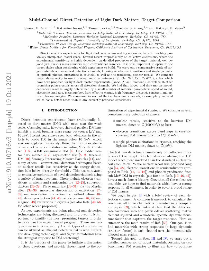
The 95% C.L. exclusion reach on σn for a light (effectivelymassless) and heavy mediator are shown in Figs. 2 and 3respectively, assuming fp = fn, an exposure of one kg-yr,and zero background events. In the rest of this sectionwe explain in detail the features in these plots.
A. Single Phonon Excitations
We first consider DM creating a single phonon via thenucleon coupling. As shown in Ref. [59],
Y j = q
(fjfn
)FNj (q) , (34)
where fj = fpZj + fn(Aj − Zj) for the nucleus at site jin a primitive cell, and FNj (q) is the nuclear form factorgiven by Eq. (13). As before, the total rate is calculatedfrom Eq. (20). However, a major difference compared tothe dark photon mediator model is that, if fp and fn havethe same sign, the rate is dominated by acoustic and notoptical phonons, assuming the energy threshold is lowenough to access the acoustic phonons. This is becauseY j points in the same direction for all j, resulting instronger in-phase oscillations as discussed in Sec. II C 1.
We first discuss Fig. 2, for the light mediator case,

9
10−3 10−2 10−1 1 10 102 103 104
mχ [MeV]
10−48
10−46
10−44
10−42
10−40
10−38
10−36σn
[cm
2 ]
Fifth Force + Pert.
Fifth Force + SIDMωmin = 1 meV
ωmin = 20 meV
ωmin = 100 meV
ωm
in =500 meV
SiGeCsIAl2O3
CaWO4
Diamond
SiGeCsIAl2O3
CaWO4
Diamond
Figure 2. Single phonon and nuclear recoil reach for a light (mφ = 1 eV) hadrophilic scalar mediator. 1, 20, and 100 meVthresholds are shown for the single phonon reach (solid, dashed, and dotted respectively), and 500 meV threshold is assumedfor the nuclear recoil reach (dot-dashed). For mφ = 1 eV the dominant constraint on fn is from fifth force experiments [88].If mχ makes up all the DM then the dominant constraint on yχ is from DM self-interactions (SIDM) [88]. If mχ is only asubcomponent, we only require perturbativity yχ < 1 (Pert.); in this case the reach curves can be easily rescaled.6
when the energy threshold, ωmin, is 1 meV. While sucha low threshold is experimentally challenging, the curvesare easier to understand conceptually compared to thehigher ωmin curves. In fact, over most of the massrange, for most materials, the rate is dominated by singlelongitudinal acoustic (LA) phonon production. At thehigh mass end, the reach is material-independent, under-stood analytically as follows. The mediator form factorFmed ∝ 1/q2, and therefore the rate is dominated bythe lowest detectable momentum transfer. In this case,we can set G = 0 (or equivalently, q = k in Eq. (20)),Wj ' 0, ωLA = cLAs q, FNj ' 1, and g(q, ω) ∝ q−1.
Lastly, in this limit q · εLA,j,k ' q√mj/mcell. Thus the
rate
R ∝ m3χ
m2cell
σnµ2χn
(∑j
fjfn
)21
ωmin. (35)
For fp = fn, we have fj ∝ Aj ∝ mcell/mn, and thedependence on the target properties drops out. The ref-erence cross section σn corresponding to a given eventrate R scales with mass as µ2
χn/m3χ, as we see in Fig. 2.
Note that as we go to higher mχ the reach on the cou-plings f2ny
2χ gets worse as µ2
χnmχ; the apparent betterreach at higher mass in Fig. 2 is due to the definition of
σn ∝ m−4χ .
For DM masses below ∼ 0.1 MeV in Fig. 2, kinematicscauses the reach to diminish: the maximum momentumtransfer, 2mχvmax, must be large enough to reach theminimum momentum transfer set by the detector thresh-old, ωmin/c
LAs . This sets the minimum reachable DM
mass
mχ,min ∼ 20 keV
(ωmin
meV
)(10−5
cLAs
). (36)
To reach the lightest dark matter particle at low thresh-olds, an ideal material is then diamond, as it has thehighest speed of sound. AlN and SiO2 are the next bestcandidates from our search.
As we move on to the curves with higher energy thresh-olds, ωmin = 20 meV and 100 meV, the materials withlower sound speed lose reach altogether. (The ωmin = 500meV curves are derived from nuclear recoil; this is dis-cussed in the next subsection.) The reason is that acous-tic phonons are accessible only when ωmin . cLAs /a,where a is the lattice spacing. For materials with lowersound speed, the energy threshold may simply never below enough to have any reach with an acoustic phonon.In addition, one can see where optical phonons start toplay a role, as the slope of the reach curve changes at
10
10−3 10−2 10−1 1 10 102 103 104
mχ [MeV]
10−47
10−46
10−45
10−44
10−43
10−42
10−41
10−40
10−39
10−38
σn
[cm
2 ]
ωmin = 1 meV
ωm
in=
20m
eV
ωmin = 100 meV
ωmin = 500 meV
ν floorSiGeCsIAl2O3
CaWO4
PbTe
CRESST− IIDarkSide− 50XENON1T
Figure 3. Single phonon and nuclear recoil reach for a massive (mφ & 400 MeV) hadrophilic scalar mediator. 1, 20, and 100 meVthresholds are shown for the single phonon reach (solid, dashed, and dotted respectively), and 500 meV threshold is assumed forthe nuclear recoil reach (dot-dashed). There are no stellar constraints for mφ & 400 MeV [88]. Currently, the best experimentalnuclear recoil constraints in this region of parameter space are from DarkSide-50 [89] (assuming binomial fluctuations), andXENON1T (combined limits from [90, 91]). We also show the constraint from CRESST-II [77], which is stronger than theDarkSide-50 constraint at low masses assuming no fluctuation in energy quenching. A more complete collection of nuclearrecoil constraints can be found in Refs. [89, 91, 92]. The neutrino floor is taken from Ref. [93].6
lower masses, e.g. Si with an energy threshold of 20 meV.This feature will be present for all materials if the lowestkinematically reachable DM mass from optical phononexcitations, given in Eq. (24), is smaller than the lowestkinematically reachable DM mass from acoustic phononexcitations, given in Eq. (36).
Next we turn our attention to Fig. 3, for the samehadrophilic scalar mediator benchmark, but with a heavymediator. Again, we first focus on the case of a 1 meVthreshold, as here the acoustic phonon contributionsdominate and analytic simplifications can be made sincethe integrals are dominated by the high momentum be-havior. There are four distinct regions in mass and wenow discuss the mass and material parameters depen-dence of each of them.
In the lowest mass regime, mχ . 10−1 MeV, the reachends when the acoustic modes are no longer kinemati-cally available, just as in the massless mediator case, withminimum reachable mass again set by Eq. (36). Between10−1 and 1 MeV, the reach curves flatten and the orderof the curves reverses: materials with a higher speed ofsound have worse reach, which can be understood ana-lytically starting with Eq. (20). For mχ . 1 MeV themomentum transfer is within the 1BZ, so we can take
q = k, Wj ' 0, ω = csq and g(q, ω) ∝ 1/q as in the lightmediator case. For simplicity we ignore angular depen-dence, assume the ions are the same, Aj ≡ A, mj ≡ m,set fn = fp, and consider only the longitudinal mode sothat q · ε ∝ q. Then we have
R ∝ σnmcellm3
χcs
∫ 2mχv
d3k1
k2
(kA√m
)2
∝ σncs, (37)
where the upper cutoff is due to kinematics and manifestsin the g function, which goes to zero as k reaches themaximum allowed momentum transfer.
A similar derivation applies to the mass dependencein the next two regimes. For 1 MeV . mX . 10 MeV,the dominant momentum transfer is outside of the 1BZ,which means that ω can no longer be approximated bycsq. In fact, since ω is only a function of the phononmomentum in the 1BZ, it will vary rapidly as q increases.We therefore exchange ω with a q independent quantity,roughly thought of as the average of ω over the whole

11
1BZ, 〈ω〉. The rate becomes
R ∝ σnmcellm3
χ〈ω〉
∫ 2mχv
d3k1
k
(kA√m
)2
∝ σnmχ
〈ω〉 . (38)
Since the rate scales inversely with 〈ω〉, materials withlower energy phonon modes are preferred. As 〈ω〉 is usu-ally correlated with cs, the ordering of the curves is thesame as in the previous regime. We have neglected theDebye-Waller factor in the analytic estimates above, be-cause the momentum transfer is on the order of mχv, and
is less than the Debye-Waller cut-off around√mN 〈ω〉.
However, for the last mass regime, above ∼ 10 MeV, thisis no longer the case, and the momentum integral is cut-off by the Debye-Waller factor,
R ∝ σnmcellmχµ2
χn〈ω〉
∫ √mN 〈ω〉0
d3k1
k
(kA√m
)2
∝ σnA2〈ω〉2
mχµ2χn
. (39)
Therefore, materials with heavier elements and higherphonon energies are preferred. In our search, CaWO4 hasthe highest factor of A〈ω〉, with PbTe following, which isthe reason we choose to highlight PbTe in Fig. 3.
For higher thresholds, the optical phonon modes con-tribute to a greater degree, so the scaling arguments givenabove for the first two mass regimes no longer hold, butfor the last two they do, which is why the curves arealmost parallel.
B. Nuclear Recoils
For DM heavier than O(100 MeV), nuclear recoils of-fer a complementary detection channel to phonon excita-tions. The low mass behavior of the reach curves is un-derstood in the same way as in Sec. III C (see Eq. (29)),and lighter elements are advantageous. At higher masses,the σn reach depends on the mediator mass. To show thisanalytically we again consider a single nucleus species,AN = A, and fn = fp. In the case of a light mediatorthe differential rate in Eq. (14) becomes
dR
dω∝ σnm
3χ
µ2χn
1
ω2η (vmin) . (40)
For DM heavier than a few hundred MeV, the mN depen-dence via η(vmin) is weak, as in the dark photon mediatorcase. The rate is then
R ∝ σnm3χ
µ2χn
1
ωmin, (41)
which is material independent. This is why all the reachcurves coincide for large DM masses. We also see that asin the case of acoustic phonons, achieving lower energy
thresholds is crucial for improving the reach.If the mediator is heavy, we have
dR
dω∝ σnA
2
mχµ2χn
η (vmin) , (42)
R ∝ σnA2
mχµ2χn
ωmax ∝σnAµ
2χN
mχµ2χn
, (43)
where for simplicity we take the η function to decreasesharply at the kinematic bound. We reach the conclusionthat heavier nuclei are preferred, similar to the case ofsingle phonon excitations with a heavy mediator. Notealso that there is no threshold dependence for largermasses. Therefore a lower threshold only helps to reachlower DM masses, as opposed to the case of the lightmediator.
V. CONCLUSIONS
We considered spin independent DM direct detectionthrough three channels – single phonon excitations, elec-tron transitions, and nuclear recoils – in a wide varietyof crystal target materials, and two well motivated DMmodels. Many of these materials are already being dis-cussed for DM detection, but we have presented somenew targets for consideration.
For each type of interaction, we specified the targetmaterial parameters which should be optimized in or-der to maximize the reach, and we found complemen-tarity between targets depending on (i) the experimen-tal threshold, (ii) the mass range, and (iii) the model.The experimental threshold dictates which modes areavailable: at higher recoil energies, only electron tran-sitions and nuclear recoils are possible; as the thresh-old drops, optical and acoustic phonons become acces-sible. The phonon modes in materials with high soundspeed become kinematically available at higher thresh-olds than in materials with lower sound speeds. Also, fora given threshold, materials with higher sound speedshave reach to lighter dark matter. Regarding the massrange, the smallest detectable masses are always set bya kinematic constraint, and the dependence on mate-rial parameters, and detection threshold, can be foundin Eqs. (24), (28), (36), (29) for optical phonon, elec-tron, acoustic phonon excitations, and nuclear recoils re-spectively. As for the model, we defined a quality factor(in Eq. (27)) for single optical phonon excitations fromdark photon mediated scattering to indicate which tar-gets will have the best sensitivity. On the other hand,for a hadrophilic mediator, target optimization for acous-tic phonon excitations depends on the mediator and DMmasses. We summarize our results in Table II.
An attractive feature of phonon and electron excita-tions is the possible daily modulation of event rates, asthe dynamic structure factors in Eqs. (15) and (18) aregenerically anisotropic. In the context of phonon excita-tions, Al2O3 has been considered in Ref. [47], and in our

12
Light dark photon mediator (Sec. III, Fig. 1)
Detection channelQuantity to maximize to reach ...
Best materials... lower mχ ... lower σe
(Optical) phonons ω−1O (Eq. (24)) quality factor Q defined in Eq. (27) SiO2, Al2O3, CaWO4
Electron transitions E−1g (Eq. (28)) depends on details of electron wavefunctions InSb, Si
Nuclear recoils (Aωmin)−1
(Eq. (29)) (Z/A)2 ω−1min (Eq. (31)) diamond, LiF
Hadrophilic scalar mediator (Sec. IV, Figs. 2, 3)
Detection channelQuantity to maximize to reach ...
Best materials... lower mχ ... lower σn
(Acoustic) phonons cs/ωmin (Eq. (36))
Light mediator: ω−1min (Eq. (35)) diamond, SiO2
Heavy mediator: c−1s or ω−1ph or Aωphall complementary
depending on mχ (Eqs. (37), (38), (39))
Nuclear recoils (Aωmin)−1
(Eq. (29))Light mediator: ω−1min (Eq. (40)) diamond, LiF
Heavy mediator: A (Eq. (43)) CsI, Pb compounds
Table II. Summary of our results. The material properties relevant for the optimization of target are: atomic mass number A,proton number Z, electronic band gap Eg, speed of sound cs, optical phonon energy ωO, average phonon energy ωph, as wellas Born effective charges and the high-frequency dielectric constant that enter the quality factor Q. Achieving lower detectorenergy thresholds ωmin is also crucial in several cases.
companion paper [59] we have discussed hexagonal boronnitride as an example of an O(eV)-gap target which ex-hibits daily modulation in electron transitions. We planon identifying other promising targets for daily modula-tion in the future.
Acknowledgments. We thank Kyle Bystrom, RouvenEssig, Matt Pyle, Adrian Soto and Tien-Tien Yu foruseful discussions. T.T. and K.Z. are supported by theQuantum Information Science Enabled Discovery (Quan-tISED) for High Energy Physics (KA2401032) at LBNL.Z.Z. is supported by the NSF Grant PHY-1638509 andDoE Contract DE-AC02-05CH11231. Development ofthe materials calculations in this paper (S.G. and K.I.)was supported by the Laboratory Directed Researchand Development Program of LBNL under the DoEContract No. DE-AC02-05CH11231. Computational re-sources were provided by the National Energy ResearchScientific Computing Center and the Molecular Foundry,DoE Office of Science User Facilities supported by theOffice of Science of the U.S. Department of Energy un-der Contract No. DE-AC02-05CH11231. The work per-formed at the Molecular Foundry was supported by theOffice of Science, Office of Basic Energy Sciences, of theU.S. Department of Energy under the same contract.
Appendix A: Calculations of Target Properties
We obtain the materials-specific responses using firstprinciples calculations based on density functional the-ory (DFT) [94]. DFT is a standard method for obtain-ing solutions to the many-electron interaction problem,and can accurately predict materials properties ab ini-tio ranging from electronic and magnetic to mechanicaland vibrational properties. For this work, we used DFTto calculate the full electronic and phonon spectra fora range of materials, with the calculation details givenbelow. However, since DFT is a ground-state method,it suffers from the famous ‘band gap’ problem whereexcited-state properties, including band gaps, are notaccurately treated using standard DFT methods. Wecorrect for this in two ways: (i) we performed beyond-DFT calculations (hybrid functional calculations) forseveral of the compounds where standard DFT gave azero band gap, and (ii) we adjusted the band gaps toexperimentally-reported values for all compounds. Wenote that the convergence parameters used for the elec-tronic and phonon calculations are different owing to thedifferent physical properties being calculated.
The list of materials calculated with their correspond-ing space groups and space group numbers is given inTable III, with the crystal structures depicted in Fig. 4.For compounds where several structural isomorphs exist,we considered the reported low-temperature ground statestructure. The Brillouin zones for the crystal structures

13
considered in this work are depicted in Fig. 5 with thehigh-symmetry points labelled. Both the electronic andphonon band structure plots take paths through thesehigh-symmetry points.
All DFT calculations were performed using the Vi-enna Ab initio Simulation Package (VASP) [95–97] withprojector augmented wave (PAW) pseudopotentials [98,99] using the Perdew-Becke-Ernzerhof (PBE) exchange-correlation functional [100]. In the PAW scheme, wetreated s and p electrons as valence for Li, C, N, O, F,Na, Al, Si, S, Cl, Ca, I, Cs and W, p electrons as valencefor Mg and d electrons as valence for Zn, Ga, Ge, As,In and Sb. Below we summarize the convergence criteriaused for the (i) electronic structure and wavefunctions,and (ii) phonon calculations.
1. Calculation details for electronic bandstructures and wavefunctions
For structural optimizations, a plane wave cutoff-energy of 950 eV was used with a 12×12×12 Γ-centeredk-point grid. The energy and force convergence criteria
were 1× 10⁻⁸ eV and 1 meVA−1
respectively.All-electron wavefunction coefficients were extracted
from PAW calculations using a modification of the paw-pyseed code [133]. This enabled recovery of the full wave-functions as normalized single-particle Kohn-Sham statesfrom the pseudo-wavefunctions obtained by the PAW-method. Initial PAW wavefunctions were calculated witha plane wave energy-cutoff of 1000 eV, from which the all-electron wavefunctions were constructed with a minimumenergy-cutoff of 450 eV. Calculations were performed us-ing Γ-centered Monkhorst-Pack grids, with a k-point den-
sity of at least 0.27A−1
. Energy bands were included upto 60 eV above and below the valence band maximum.However, since there is no pseudopotential containing thelow-lying 4d -states for indium in VASP, these bands areneglected from the calculations. In NaI and CsI the I4d states are positioned at approximately 43 eV and 42eV below the valence band maxima respectively. A scis-sor operator was applied to match the experimental bandgaps given in Table I. For Ge, InSb and GaSb, the PBEfunctional gave partially occupied bands due to under-estimation of the band gap. In these cases the HSE06hybrid functional [134] was applied in a static calcula-tion to introduce a band gap before applying the scissorcorrection. Electronic band structures were computed ona discrete k-mesh along the high-symmetry directions.
PbS, PbSe and PbTe were excluded from the electroncalculations because spin-orbit interactions are requiredto capture important features of the band structures andspin-orbit coupling is not yet implemented within thepawpyseed code.
Multiple k-point densities, energy-cutoffs, and energybands included were tested for all materials to ensureconvergence of the scattering rates to less than 2% atmχ = 10 GeV, less than 3% at mχ = 10 MeV, and less
than 28%, 18%, 18% and 10% for GaAs, GaSb, Ge, andSi at mχ = 1 MeV respectively. InSb was tested with a12 × 12 × 12 and 14 × 14 × 14 k-point grid, plotted asdotted and solid curves in Fig. 1 respectively. At mχ = 1MeV the rate convergence is 5%, and decreases for largermasses. However at smaller masses the G = 0 contribu-tion, from momentum transfers within the 1BZ, and en-ergy depositions below ∼ 1 eV, dominate the rate. Theslow convergence here is due to the fact that InSb hasrapidly changing band structure near the Γ point, andmore k-points are needed for better convergence. Theseuncertainties are plotted as shaded bands in Fig. 1, andaccompanying figures in Appendix B, although most areinvisible due to the plots being log-log.
2. Calculation details for phonon spectra
We obtained the phonon dispersions fromPhonopy [135] using the ‘frozen-phonon’ methodby diagonalizing the force matrix using VASP as theforce calculator. For the VASP calculations, the elec-tronic wavefunctions were expanded in a plane-wavebasis with a kinetic-energy cutoff of 600 eV. The Bril-
louin zone sampling was no less than 0.8A−1
in eachdirection of the unit cell with Monkhorst-Pack grids,and was correspondingly scaled for phonon supercellcalculations. Born effective charges were calculated forpolar materials using density-functional perturbationtheory as implemented in VASP.
3. Parameters in Table I
The experimental electronic band gaps, Eg, are takenfrom references cited in Table III. The speed of sound,cLAs , was calculated by averaging ωLA/q over a uniform20×20 grid on the surface of a sphere in reciprocal spacewith radius q ≈ 10 eV centered at the Γ point. The sameaveraging procedure was used in calculating the range ofoptical modes, ωO, when a range exists. The average
Born effective charge, Z∗, is defined as Tr
[Z∗+]/3, where
Z∗+ is the Born effective charge of the positive ion(s) (theother charges can be found by requiring that the primi-tive cell is neutral). The average high frequency dielectricconstant, ε∞, is defined as Tr [ε∞] /3.
Appendix B: Additional Target Comparison Plots
In this Appendix, we provide plots for the remainderof the materials in Table I not presented in the maintext. For concreteness, in all figures we take the local DMdensity to be ρχ = 0.4 GeV/cm3, and assume a Maxwell-Boltzmann distribution with velocity dispersion v0 = 230km/s, truncated at the escape velocity vesc = 600 km/s,and boosted to the target rest frame by the Earth ve-locity in the galactic rest frame vE = 240 km/s. We

14
Lattice Parameters (A) Space group Structure EgMaterial a (el., ph., exp.) c (el., ph. exp.) (number) Calc. Eg (eV) Ref. Ref.
Al2O3 4.808, 4.805, 4.759 13.121, 13.116, 12.991 R3c (167) 5.84 [101] [102]
AlN 3.130, 3.128, 3.111 5.020, 5.016, 4.978 P63mc (186) 4.02 [103] [104]
CaF2 5.507, 5.499, 5.463 – Fm3m (225) 11.81 [105] [106]
CaWO4 5.317, 5.320, 5.243 11.534, 11.444, 11.376 I41/a (88) 4.04 [107] [108]
CsI 4.671, 4.669, 4.567 – Pm3m (221) 3.67 [103] [109]
Diamond 3.572, 3.572, 3.567 – Fd3m (227) 4.12 [103] [110]
GaAs 5.751, 5.756, 5.653 – F43m (216) 0.141 [103] [111]
GaN 3.129, 3.247, 3.189 5.246, 5.280, 5.186 P63mc (186) 1.71 [112] [113]
GaSb 6.217, 6.223, 6.118 – F43m (216) 0.47 [103] [114]
Ge 5.763, 5.782, 5.657 – Fd3m (227) 0.37 [103] [115]
InSb 6.635, 6.634, 6.478 – F43m (216) 0.06 [103] [116]
LiF 4.063, 4.065, 4.020 – Fm3m (225) 8.85 [117] [118]
MgF2 4.702, 4.684, 4.623 3.097, 3.081, 3.052 P42/mnm (136) 6.79 [103] [119]
MgO 4.258, 4.250, 4.211 – Fm3m (225) 4.43 [120] [121]
NaCl 5.670, 5.696, 5.641 – Fm3m (225) 5.05 [103] [122]
NaF 4.682, 4.619, 4.634 – Fm3m (225) 6.14 [123] [124]
NaI 6.498, 6.530, 6.473 – Fm3m (225) 3.61 [103] [125]
PbS –, 5.994, 5.936 – Fm3m (225) – [103] [126]
PbSe –, 6.206, 6.124 – Fm3m (225) – [103] [126]
PbTe –, 6.561, 6.454 – Fm3m (225) – [103] [126]
Si 5.469, 5.469, 5.431 – Fd3m (227) 0.75 [103] [127]
SiO2 5.038, 5.016, 4.913 5.526, 5.507, 5.405 P3221 (154) 5.66 [128] [129]
ZnO 3.288, 3.287, 3.250 5.308, 5.304, 5.207 P63mc (186) 0.72 [103] [130]
ZnS 5.449, 5.443, 5.420 – F43m (216) 2.01 [131] [132]
Table III. List of material properties used in DFT calculations. The calculated lattice parameters (a and c) are listed for boththose used in the electronic (el.) and phonon (ph.) excitation calculations, along with reported experimental values (exp.).The space group and corresponding space group number are included for the crystal strucrures considered. The PBE-levelcalculated band gaps are also listed, with details explained in the text.
take the direction of the Earth’s velocity to be in thez direction with respect to the crystal coordinates whencomputing the reach (for most of the target materialswe consider here we expect modulation effects from theEarth’s motion to be small). The constraints on σ corre-spond to a 95% confidence level (C.L.) assuming Poissondistributed counts and no events are seen (equivalently,
the constraint corresponds to the cross section needed toobtain three events). We chose the 95% C.L. for easiercomparison with previous literature. Because it is alsostandard to compute the 90% C.L. exclusion reach, wenote that one simply has to mulitply the 95% C.L. ex-clusion reach by 2.3/3 (as the 90% C.L. constraint corre-sponds to the cross section needed to obtain 2.3 events).We also assume an exposure of one kg-yr.
[1] C. Boehm and P. Fayet, Nucl. Phys. B683, 219 (2004),arXiv:hep-ph/0305261 [hep-ph].
[2] M. Pospelov, A. Ritz, and M. B. Voloshin, Phys. Lett.B662, 53 (2008), arXiv:0711.4866 [hep-ph].
[3] D. Hooper and K. M. Zurek, Phys. Rev. D77, 087302(2008), arXiv:0801.3686 [hep-ph].
[4] J. Kumar and J. L. Feng, Proceedings, 7th Interna-tional Conference on Supersymmetry and the Unifica-tion of Fundamental Interactions (SUSY09): Boston,USA, June 5-10, 2009, AIP Conf. Proc. 1200, 1059(2010), arXiv:0909.2877 [hep-ph].
[5] N. Arkani-Hamed and N. Weiner, JHEP 12, 104 (2008),arXiv:0810.0714 [hep-ph].
[6] C. Cheung, J. T. Ruderman, L.-T. Wang, and I. Yavin,Phys. Rev. D80, 035008 (2009), arXiv:0902.3246 [hep-ph].
[7] D. E. Morrissey, D. Poland, and K. M. Zurek, JHEP07, 050 (2009), arXiv:0904.2567 [hep-ph].
[8] D. E. Kaplan, M. A. Luty, and K. M. Zurek, Phys. Rev.D79, 115016 (2009), arXiv:0901.4117 [hep-ph].
[9] T. Cohen, D. J. Phalen, A. Pierce, and K. M. Zurek,Phys. Rev. D82, 056001 (2010), arXiv:1005.1655 [hep-
15
ph].[10] L. J. Hall, K. Jedamzik, J. March-Russell, and S. M.
West, JHEP 03, 080 (2010), arXiv:0911.1120 [hep-ph].[11] Y. Hochberg, E. Kuflik, T. Volansky, and J. G. Wacker,
Phys. Rev. Lett. 113, 171301 (2014), arXiv:1402.5143[hep-ph].
[12] R. Essig, J. Mardon, and T. Volansky, Phys. Rev. D85,076007 (2012), arXiv:1108.5383 [hep-ph].
[13] P. W. Graham, D. E. Kaplan, S. Rajendran, and M. T.Walters, Phys. Dark Univ. 1, 32 (2012), arXiv:1203.2531[hep-ph].
[14] R. Essig, A. Manalaysay, J. Mardon, P. Sorensen, andT. Volansky, Phys. Rev. Lett. 109, 021301 (2012),arXiv:1206.2644 [astro-ph.CO].
[15] S. K. Lee, M. Lisanti, S. Mishra-Sharma, and B. R.Safdi, Phys. Rev. D92, 083517 (2015), arXiv:1508.07361[hep-ph].
[16] R. Essig, M. Fernandez-Serra, J. Mardon, A. Soto,T. Volansky, and T.-T. Yu, JHEP 05, 046 (2016),arXiv:1509.01598 [hep-ph].
[17] Y. Hochberg, Y. Kahn, M. Lisanti, C. G. Tully,and K. M. Zurek, Phys. Lett. B772, 239 (2017),arXiv:1606.08849 [hep-ph].
[18] S. Derenzo, R. Essig, A. Massari, A. Soto, and T.-T.Yu, Phys. Rev. D96, 016026 (2017), arXiv:1607.01009[hep-ph].
[19] Y. Hochberg, T. Lin, and K. M. Zurek, Phys. Rev.D95, 023013 (2017), arXiv:1608.01994 [hep-ph].
[20] I. M. Bloch, R. Essig, K. Tobioka, T. Volansky, andT.-T. Yu, JHEP 06, 087 (2017), arXiv:1608.02123 [hep-ph].
[21] R. Essig, T. Volansky, and T.-T. Yu, Phys. Rev. D96,043017 (2017), arXiv:1703.00910 [hep-ph].
[22] F. Kadribasic, N. Mirabolfathi, K. Nordlund, A. E.Sand, E. Holmstrom, and F. Djurabekova, Phys. Rev.Lett. 120, 111301 (2018), arXiv:1703.05371 [physics.ins-det].
[23] N. A. Kurinsky, T. C. Yu, Y. Hochberg, and B. Cabrera,Phys. Rev. D99, 123005 (2019), arXiv:1901.07569 [hep-ex].
[24] M. Heikinheimo, K. Nordlund, K. Tuominen, andN. Mirabolfathi, Phys. Rev. D99, 103018 (2019),arXiv:1903.08654 [hep-ph].
[25] T. Emken, R. Essig, C. Kouvaris, and M. Sholapurkar,JCAP 1909, 070 (2019), arXiv:1905.06348 [hep-ph].
[26] Y. Hochberg, Y. Zhao, and K. M. Zurek, Phys. Rev.Lett. 116, 011301 (2016), arXiv:1504.07237 [hep-ph].
[27] Y. Hochberg, M. Pyle, Y. Zhao, and K. M. Zurek,JHEP 08, 057 (2016), arXiv:1512.04533 [hep-ph].
[28] Y. Hochberg, T. Lin, and K. M. Zurek, Phys. Rev.D94, 015019 (2016), arXiv:1604.06800 [hep-ph].
[29] Y. Hochberg, Y. Kahn, M. Lisanti, K. M. Zurek, A. G.Grushin, R. Ilan, S. M. Griffin, Z.-F. Liu, S. F. We-ber, and J. B. Neaton, Phys. Rev. D97, 015004 (2018),arXiv:1708.08929 [hep-ph].
[30] A. Coskuner, A. Mitridate, A. Olivares, and K. M.Zurek, (2019), arXiv:1909.09170 [hep-ph].
[31] R. M. Geilhufe, F. Kahlhoefer, and M. W. Winkler,(2019), arXiv:1910.02091 [hep-ph].
[32] M. Ibe, W. Nakano, Y. Shoji, and K. Suzuki, JHEP03, 194 (2018), arXiv:1707.07258 [hep-ph].
[33] M. J. Dolan, F. Kahlhoefer, and C. McCabe, Phys. Rev.Lett. 121, 101801 (2018), arXiv:1711.09906 [hep-ph].
[34] N. F. Bell, J. B. Dent, J. L. Newstead, S. Sabharwale,and T. J. Weiler, (2019), arXiv:1905.00046 [hep-ph].
[35] D. Baxter, Y. Kahn, and G. Krnjaic, (2019),arXiv:1908.00012 [hep-ph].
[36] R. Essig, J. Pradler, M. Sholapurkar, and T.-T. Yu,(2019), arXiv:1908.10881 [hep-ph].
[37] R. Essig, J. Mardon, O. Slone, and T. Volansky, Phys.Rev. D95, 056011 (2017), arXiv:1608.02940 [hep-ph].
[38] A. Arvanitaki, S. Dimopoulos, and K. Van Tilburg,Phys. Rev. X8, 041001 (2018), arXiv:1709.05354 [hep-ph].
[39] R. Essig, J. Perez-Rıos, H. Ramani, and O. Slone,(2019), arXiv:1907.07682 [hep-ph].
[40] K. Schutz and K. M. Zurek, Phys. Rev. Lett. 117,121302 (2016), arXiv:1604.08206 [hep-ph].
[41] S. Knapen, T. Lin, and K. M. Zurek, Phys. Rev. D95,056019 (2017), arXiv:1611.06228 [hep-ph].
[42] F. Acanfora, A. Esposito, and A. D. Polosa, Eur. Phys.J. C79, 549 (2019), arXiv:1902.02361 [hep-ph].
[43] A. Caputo, A. Esposito, and A. D. Polosa, (2019),arXiv:1907.10635 [hep-ph].
[44] R. Budnik, O. Chesnovsky, O. Slone, and T. Volansky,Phys. Lett. B782, 242 (2018), arXiv:1705.03016 [hep-ph].
[45] S. Rajendran, N. Zobrist, A. O. Sushkov, R. Walsworth,and M. Lukin, Phys. Rev. D96, 035009 (2017),arXiv:1705.09760 [hep-ph].
[46] S. Knapen, T. Lin, M. Pyle, and K. M. Zurek, Phys.Lett. B785, 386 (2018), arXiv:1712.06598 [hep-ph].
[47] S. Griffin, S. Knapen, T. Lin, and K. M. Zurek, Phys.Rev. D98, 115034 (2018), arXiv:1807.10291 [hep-ph].
[48] T. Trickle, Z. Zhang, and K. M. Zurek, (2019),arXiv:1905.13744 [hep-ph].
[49] C. J. Riedel, Phys. Rev. D88, 116005 (2013),arXiv:1212.3061 [quant-ph].
[50] C. Kouvaris and J. Pradler, Phys. Rev. Lett. 118,031803 (2017), arXiv:1607.01789 [hep-ph].
[51] C. J. Riedel and I. Yavin, Phys. Rev. D96, 023007(2017), arXiv:1609.04145 [quant-ph].
[52] G. Cavoto, F. Luchetta, and A. D. Polosa, Phys. Lett.B776, 338 (2018), arXiv:1706.02487 [hep-ph].
[53] D. J. E. Marsh, K.-C. Fong, E. W. Lentz, L. Smejkal,and M. N. Ali, Phys. Rev. Lett. 123, 121601 (2019),arXiv:1807.08810 [hep-ph].
[54] R. Alonso, D. Blas, and P. Wolf, JHEP 07, 069 (2019),arXiv:1810.00889 [hep-ph].
[55] B. M. Roberts et al., (2019), arXiv:1907.02661 [astro-ph.CO].
[56] M. Zarei, S. Shakeri, M. Abdi, D. J. E. Marsh, andS. Matarrese, (2019), arXiv:1910.09973 [hep-ph].
[57] M. W. Goodman and E. Witten, Physical Review D 31,3059 (1985).
[58] A. K. Drukier, K. Freese, and D. N. Spergel, PhysicalReview D 33, 3495 (1986).
[59] T. Trickle, Z. Zhang, K. M. Zurek, K. Inzani, andS. Griffin, http://arxiv.org/abs/1910.08092v1.
[60] J. R. T. de Mello Neto et al. (DAMIC), Proceed-ings, 34th International Cosmic Ray Conference (ICRC2015): The Hague, The Netherlands, July 30-August 6,2015, PoS ICRC2015, 1221 (2016), arXiv:1510.02126[physics.ins-det].
[61] A. Aguilar-Arevalo et al. (DAMIC), Phys. Rev. Lett.123, 181802 (2019), arXiv:1907.12628 [astro-ph.CO].

16
[62] O. Abramoff et al. (SENSEI), Phys. Rev. Lett. 122,161801 (2019), arXiv:1901.10478 [hep-ex].
[63] R. Agnese et al. (SuperCDMS), Phys. Rev. Lett. 112,241302 (2014), arXiv:1402.7137 [hep-ex].
[64] R. Agnese et al. (SuperCDMS), Phys. Rev. D95, 082002(2017), arXiv:1610.00006 [physics.ins-det].
[65] R. Agnese et al. (SuperCDMS), Phys. Rev. Lett. 116,071301 (2016), arXiv:1509.02448 [astro-ph.CO].
[66] R. Agnese et al. (SuperCDMS), Phys. Rev. D97, 022002(2018), arXiv:1707.01632 [astro-ph.CO].
[67] R. Agnese et al. (SuperCDMS), Phys. Rev. D99, 062001(2019), arXiv:1808.09098 [astro-ph.CO].
[68] R. Agnese et al. (SuperCDMS), Phys. Rev.Lett. 121, 051301 (2018), [erratum: Phys. Rev.Lett.122,no.6,069901(2019)], arXiv:1804.10697 [hep-ex].
[69] S. Baum, K. Freese, and C. Kelso, Physics Letters B789, 262 (2019).
[70] K. Kim (KIMS), in Proceedings, Meeting of the APS Di-vision of Particles and Fields (DPF 2015): Ann Arbor,Michigan, USA, 4-8 Aug 2015 (2015) arXiv:1511.00023[physics.ins-det].
[71] J. Amare et al., Phys. Rev. Lett. 123, 031301 (2019),arXiv:1903.03973 [astro-ph.IM].
[72] E. Shields, J. Xu, and F. Calaprice, Physics Procedia61, 169 (2015).
[73] J. H. Jo (DM-Ice), Proceedings, 38th Interna-tional Conference on High Energy Physics (ICHEP2016): Chicago, IL, USA, August 3-10, 2016,PoS ICHEP2016, 1223 (2017), arXiv:1612.07426[physics.ins-det].
[74] S. K. Kim and the KIMS Collaboration, Journal ofPhysics: Conference Series 120, 042021 (2008).
[75] C. Cozzini et al., Low temperature detectors. Proceed-ings, 9th International Workshop, LTD-9, Madison,USA, July 22-27, 2001, AIP Conf. Proc. 605, 481(2002).
[76] F. Petricca et al. (CRESST), in 15th International Con-ference on Topics in Astroparticle and UndergroundPhysics (TAUP 2017) Sudbury, Ontario, Canada, July24-28, 2017 (2017) arXiv:1711.07692 [astro-ph.CO].
[77] G. Angloher et al. (CRESST), Eur. Phys. J. C76, 25(2016), arXiv:1509.01515 [astro-ph.CO].
[78] A. Coskuner, D. M. Grabowska, S. Knapen, andK. M. Zurek, Phys. Rev. D100, 035025 (2019),arXiv:1812.07573 [hep-ph].
[79] T. Trickle, Z. Zhang, and K. M. Zurek,“https://phonodark.caltech.edu,” (2021).
[80] X. Chu, T. Hambye, and M. H. G. Tytgat, JCAP 1205,034 (2012), arXiv:1112.0493 [hep-ph].
[81] C. Dvorkin, T. Lin, and K. Schutz, Phys. Rev. D99,115009 (2019), arXiv:1902.08623 [hep-ph].
[82] H. Vogel and J. Redondo, JCAP 1402, 029 (2014),arXiv:1311.2600 [hep-ph].
[83] P. Agnes et al. (DarkSide), Phys. Rev. Lett. 121, 111303(2018), arXiv:1802.06998 [astro-ph.CO].
[84] E. Aprile et al. (XENON100), J. Phys. G41, 035201(2014), arXiv:1311.1088 [physics.ins-det].
[85] K. Miuchi, M. Minowa, A. Takeda, H. Sekiya,Y. Shimizu, Y. Inoue, W. Ootani, and Y. Ootuka, As-tropart. Phys. 19, 135 (2003), arXiv:astro-ph/0204411[astro-ph].
[86] F. Detraux, P. Ghosez, and X. Gonze, Phys. Rev. B56, 983 (1997).
[87] J. E. Peralta, J. Heyd, G. E. Scuseria, and R. L.Martin, Physical Review B 74 (2006), 10.1103/phys-revb.74.073101.
[88] S. Knapen, T. Lin, and K. M. Zurek, Phys. Rev. D96,115021 (2017), arXiv:1709.07882 [hep-ph].
[89] P. Agnes et al. (DarkSide), Phys. Rev. Lett. 121, 081307(2018), arXiv:1802.06994 [astro-ph.HE].
[90] E. Aprile et al. (XENON), Phys. Rev. Lett. 121, 111302(2018), arXiv:1805.12562 [astro-ph.CO].
[91] E. Aprile et al. (XENON), Phys. Rev. Lett. 123, 251801(2019), arXiv:1907.11485 [hep-ex].
[92] D. S. Akerib et al. (LUX), Phys. Rev. Lett. 122, 131301(2019), arXiv:1811.11241 [astro-ph.CO].
[93] M. Battaglieri et al., in U.S. Cosmic Visions: New Ideasin Dark Matter College Park, MD, USA, March 23-25,2017 (2017) arXiv:1707.04591 [hep-ph].
[94] R. M. Martin, Electronic Structure (Cambridge Univer-sity Press, 2004).
[95] G. Kresse and J. Hafner, Physical Review B 47, 558(1993).
[96] G. Kresse and J. Hafner, Physical Review B 49, 14251(1994).
[97] G. Kresse and J. Furthmuller, Computational MaterialsScience 6, 15 (1996).
[98] P. E. Blochl, Physical Review B 50, 17953 (1994).[99] G. Kresse and D. Joubert, Physical Review B 59, 1758
(1999).[100] J. P. Perdew, K. Burke, and M. Ernzerhof, Physical
Review Letters 77, 3865 (1996).[101] X.-L. Wang, C. R. Hubbard, K. B. Alexander, P. F.
Becher, J. A. Fernandez-Baca, and S. Spooner, Journalof the American Ceramic Society 77, 1569 (1994).
[102] R. H. French, Journal of the American Ceramic Society73, 477 (1990).
[103] J. Zemann, Acta Crystallographica 18, 139 (1965).[104] W. M. Yim, E. J. Stofko, P. J. Zanzucchi, J. I. Pankove,
M. Ettenberg, and S. L. Gilbert, Journal of AppliedPhysics 44, 292 (1973).
[105] S. Speziale and T. S. Duffy, Physics and Chemistry ofMinerals 29, 465 (2002).
[106] G. W. Rubloff, Physical Review B 5, 662 (1972).[107] A. Senyshyn, H. Kraus, V. B. Mikhailik, and
V. Yakovyna, Physical Review B 70 (2004),10.1103/physrevb.70.214306.
[108] V. B. Mikhailik, H. Kraus, D. Wahl, M. Itoh, M. Koike,and I. K. Bailiff, Physical Review B 69 (2004),10.1103/physrevb.69.205110.
[109] M. J. Lipp, C. H. Yoo, D. Strachan, and W. B.Daniels, Physical Review B 73 (2006), 10.1103/phys-revb.73.085121.
[110] P. J. D. C. D. Clark and P. V. Harris, Proceedings ofthe Royal Society of London. Series A. Mathematicaland Physical Sciences 277, 312 (1964).
[111] M. Levinshtein, S. Rumyantsev, and M. Shur, HandbookSeries on Semiconductor Parameters (WORLD SCIEN-TIFIC, 1996).
[112] W. Paszkowicz, S. Podsiad lo, and R. Minikayev, Jour-nal of Alloys and Compounds 382, 100 (2004).
[113] H. Teisseyre, P. Perlin, T. Suski, I. Grzegory,S. Porowski, J. Jun, A. Pietraszko, and T. D. Mous-takas, Journal of Applied Physics 76, 2429 (1994).
[114] S. Adachi, Journal of Applied Physics 66, 6030 (1989).[115] S. Sze and J. Irvin, Solid-State Electronics 11, 599
(1968).

17
[116] C. L. Littler and D. G. Seiler, Applied Physics Letters46, 986 (1985).
[117] H.-J. Ullrich, A. Uhlig, G. Geise, H. Horn, andH. Waltinger, Mikrochimica Acta 107, 283 (1992).
[118] G. Singh and T. Gallon, Solid State Communications51, 281 (1984).
[119] J. Thomas, G. Stephan, J. C. Lemonnier, M. Nisar, andS. Robin, Physica Status Solidi (b) 56, 163 (1973).
[120] in II-VI and I-VII Compounds; Semimagnetic Com-pounds (Springer-Verlag) pp. 1–6.
[121] R. Whited, C. J. Flaten, and W. Walker, Solid StateCommunications 13, 1903 (1973).
[122] F. C. Brown, C. Gahwiller, H. Fujita, A. B. Kunz,W. Scheifley, and N. Carrera, Physical Review B 2,2126 (1970).
[123] V. T. Deshpande, Acta Crystallographica 14, 794(1961).
[124] G. Roy, G. Singh, and T. Gallon, Surface Science 152-153, 1042 (1985).
[125] P. A. Rodnyi, Physical Processes in Inorganic Scintil-lators (Laser & Optical Science & Technology) (CRCPress, 1997).
[126] W. H. Strehlow and E. L. Cook, Journal of Physical andChemical Reference Data 2, 163 (1973).
[127] R. Ahrenkiel, S. Johnston, W. Metzger, and P. Dippo,Journal of Electronic Materials 37, 396 (2007).
[128] Y. L. Page and G. Donnay, Acta Crystallographica Sec-tion B Structural Crystallography and Crystal Chem-istry 32, 2456 (1976).
[129] S. A. Sato, K. Yabana, Y. Shinohara, T. Otobe, K.-M.Lee, and G. F. Bertsch, Physical Review B 92 (2015),10.1103/physrevb.92.205413.
[130] V. Srikant and D. R. Clarke, Journal of Applied Physics83, 5447 (1998).
[131] E. A. Jumpertz, Zeitschrift fur Elektrochemie und ange-wandte physikalische Chemie 59, 419 (1955).
[132] B. Khamala, L. Franklin, Y. Malozovsky, A. Stewart,H. Saleem, and D. Bagayoko, Computational Con-densed Matter 6, 18 (2016).
[133] K. Bystrom, D. Broberg, S. Dwaraknath, K. A. Persson,and M. Asta, http://arxiv.org/abs/1904.11572v1.
[134] A. V. Krukau, O. A. Vydrov, A. F. Izmaylov, and G. E.Scuseria, The Journal of Chemical Physics 125, 224106(2006).
[135] A. Togo and I. Tanaka, Scripta Materialia 108, 1 (2015).[136] Y. Hinuma, G. Pizzi, Y. Kumagai, F. Oba, and
I. Tanaka, arXiv:1602.06402.

18
(a) Diamond: diamond-C,Si, Ge. Two interpene-trating face centered cubiclattices, one offset by 1/4along the cubic diagonal.Each atom has four nearestneighbors, forming corner-sharing tetrahedra.
(b) Zincblende: ZnS, GaAs,InSb, GaSb. Same arrange-ment as diamond cubic, butwith two atom types, eachoccupying one of the facecentered cubic lattices.
(c) Rock salt: NaCl, MgO,LiF, NaF, NaI, PbS, PbSe,PbTe. The two atom typeseach form a face centeredcubic lattice, offset by 1/2along the cubic axis. Oneatom type is octahedrallycoordinated to the otheratom type and vice versa.
(d) Fluorite: CaF2. Caions form a face centeredcubic lattice. Each Ca ionis surrounded by eight Fions in a cubic geometry.
(e) CsI. The two atomtypes form interpenetrat-ing primitive cubic lattices,with an atom of one typeat the center of each cubeof the other type.
(f) α-quartz: SiO2. EachSi ion is bonded to fourO ions, forming corner-sharing tetrahedra.
(g) Corundum: Al2O3.Each Al ion is bonded tosix O ions, forming octahe-dra with a mixture of cor-ner, edge and face-sharingconnectivities.
(h) Rutile: MgF2. EachMg ion is bonded to sixF ions, forming octahedrawith a mixture of cornerand edge-sharing connec-tivities.
(i) Wurtzite: GaN, AlN,ZnO. One atom type istetrahedrally bonded to theother atom type and viceversa. The tetrahedraare corner-sharing and thestructure is a member ofthe hexagonal crystal sys-tem.
(j) CaWO4. Each Ca ion isbonded to eight O ions, andeach W ion is bonded tofour O ions, forming corner-sharing octahedra.
Figure 4. Crystal structures of targets in Table I.

19
(a) Simple cubic: CsI. (b) Face centered cubic: Diamond,Si, Ge, GaAs, InSb, GaSb, ZnS,NaCl, MgO, LiF, NaF, NaI, PbS,PbSe, PbTe, CaF2.
(c) Simple tetragonal: MgF2.
(d) Body centered tetragonal: CaWO4. (e) Hexagonal: SiO2, GaN, AlN, ZnO. (f) Rhomohedral: Al2O3.
Figure 5. First Brillouin zones of targets in Table I, with high symmetry points labeled.

20
Γ T H2|H0 L Γ S0|S2F Γ−8
−4
0
4
8
12
16
Energy[eV]
Al2O3
Γ M K Γ A L H A|LM|H K
−4
0
4
8
12
Energy
[eV]
AlN
Γ X U|K Γ L W X
0
5
10
15
20
Energy
[eV]
CaF2
Γ X P N Γ M S|S0 Γ|XR|G M
−2
0
2
4
6
8
Energy
[eV]
CaWO4
Γ X M Γ R X|R M
0.0
2.5
5.0
7.5
10.0Energy[eV]
CsI
Γ X U|K Γ L W X
−20
−10
0
10
20
30
Energy
[eV]
Diamond
Γ X U|K Γ L W X−8
−4
0
4
8
12
Energy
[eV]
GaAs
Γ M K Γ A L H A|LM|H K
−6
−3
0
3
6
9
Energy
[eV]
GaN
Γ X U|K Γ L W X
−6
−3
0
3
6
Energy
[eV]
GaSb
Γ X U|K Γ L W X
−10
−5
0
5
10
Energy
[eV]
Ge
Γ X U|K Γ L W X
−5.0
−2.5
0.0
2.5
5.0
Energy
[eV]
InSb
Γ X U|K Γ L W X
0
5
10
15
20
25
Energy
[eV]
LiF
Figure 6. Calculated electronic band structures of targets in Table I.

21
Γ X M Γ Z R A Z|X R|M A−5
0
5
10
15
20
25
Energy[eV]
MgF2
Γ X U|K Γ L W X−5
0
5
10
15
20
Energy[eV]
MgO
Γ X U|K Γ L W X
0
4
8
12
16
Energy
[eV]
NaCl
Γ X U|K Γ L W X
0
5
10
15
20
Energy
[eV]
NaF
Γ X U|K Γ L W X−2.5
0.0
2.5
5.0
7.5
10.0
12.5
Energy[eV]
NaI
Γ X U|K Γ L W X−12
−8
−4
0
4
8
12
Energy
[eV]
Si
Γ M K Γ A L H A|L M|H K−4
0
4
8
12
16
Energy
[eV]
SiO2
Γ M K Γ A L H A|LM|H K
−4
0
4
8
12
Energy
[eV]
ZnO
Γ X U|K Γ L W X
−4
0
4
8
12
Energy
[eV]
ZnS
Figure 7. Calculated electronic band structures of targets in Table I.

22
10
20
30
40
50
60
70
80
90
100
10
20
30
40
50
60
70
80
90
100
110
5
10
15
20
25
30
35
40
45
50
55
10
20
30
40
50
60
70
80
90
100
5
10
102030405060708090
100110120130140150160
5
10
15
20
25
30
35
51015202530354045505560657075808590
5
10
15
20
25
5
10
15
20
25
30
35
5
10
15
20
51015202530354045505560657075
Figure 8. Phonon dispersions calculated with VASP and phonopy [135] including non-analytic corrections. The path throughthe high symmetry points is found using SeeK-path [136].

23
51015202530354045505560657075
5101520253035404550556065707580
5
10
15
20
25
30
5
10
15
20
25
30
35
40
45
50
5
10
15
20
5
10
15
20
25
5
10
15
5
10
5
10
15
20
25
30
35
40
45
50
55
60
102030405060708090
100110120130140150
5
10
15
20
25
30
35
40
45
50
55
60
65
5
10
15
20
25
30
35
40
Figure 9. Phonon dispersions calculated with VASP and phonopy [135] including non-analytic corrections. The path throughthe high symmetry points is found using SeeK-path [136].

24
10−3 10−2 10−1 1 10 102 103 104
mχ [MeV]
10−48
10−46
10−44
10−42
10−40
10−38
10−36
10−34
10−32
σe
[cm
2 ]
Stellar
Freeze− In
AlNCaF2
DiamondGaAsGaNGaSb
XENON10DarkSide− 50XENON100SuperCDMSSENSEIDAMIC
Figure 10. Same as Fig. 1, but with different materials. For reference, gray lines are CsI, Si, and Al2O3 taken from Fig. 1.
10−3 10−2 10−1 1 10 102 103 104
mχ [MeV]
10−48
10−46
10−44
10−42
10−40
10−38
10−36
10−34
10−32
σe
[cm
2 ]
Stellar
Freeze− In
LiFMgF2
MgONaClNaFNaI
XENON10DarkSide− 50XENON100SuperCDMSSENSEIDAMIC
Figure 11. Same as Fig. 1, but with different materials. For reference, gray lines are CsI, Si, and Al2O3 taken from Fig. 1.

25
10−3 10−2 10−1 1 10 102 103 104
mχ [MeV]
10−48
10−46
10−44
10−42
10−40
10−38
10−36
10−34
10−32
σe
[cm
2 ]
Stellar
Freeze− In
PbSPbSePbTeZnOZnS
XENON10DarkSide− 50XENON100SuperCDMSSENSEIDAMIC
Figure 12. Same as Fig. 1, but with different materials. For reference, gray lines are CsI, Si, and Al2O3 taken from Fig. 1.
10−3 10−2 10−1 1 10 102 103 104
mχ [MeV]
10−48
10−46
10−44
10−42
10−40
10−38
10−36
σn
[cm
2 ]
Fifth Force + Pert.
Fifth Force + SIDMωmin = 1 meV
ωmin = 20 meV
ωmin = 100 meV
ωm
in =500 meV
AlNCaF2
GaAsGaNGaNInSb
AlNCaF2
GaAsGaNGaNInSb
Figure 13. Same as Fig. 2, but with different materials. For reference, gray lines are CsI, Si, and Al2O3 taken from Fig. 2.

26
10−3 10−2 10−1 1 10 102 103 104
mχ [MeV]
10−48
10−46
10−44
10−42
10−40
10−38
10−36σn
[cm
2 ]
Fifth Force + Pert.
Fifth Force + SIDMωmin = 1 meV
ωmin = 20 meV
ωmin = 100 meV
ωm
in =500 meV
LiFMgF2
MgONaClNaFNaI
LiFMgF2
MgONaClNaFNaI
Figure 14. Same as Fig. 2, but with different materials. For reference, gray lines are CsI, Si, and Al2O3 taken from Fig. 2.
10−3 10−2 10−1 1 10 102 103 104
mχ [MeV]
10−48
10−46
10−44
10−42
10−40
10−38
10−36
σn
[cm
2 ]
Fifth Force + Pert.
Fifth Force + SIDMωmin = 1 meV
ωmin = 20 meV
ωmin = 100 meV
ωm
in =500 meV
PbSPbSePbTeSiO2
ZnOZnS
PbSPbSePbTeSiO2
ZnOZnS
Figure 15. Same as Fig. 2, but with different materials. For reference, gray lines are CsI, Si, and Al2O3 taken from Fig. 2.

27
10−3 10−2 10−1 1 10 102 103 104
mχ [MeV]
10−47
10−46
10−45
10−44
10−43
10−42
10−41
10−40
10−39
10−38
σn
[cm
2 ]
ωmin = 1 meV
ωm
in=
20m
eV
ωmin = 100 meV
ωmin = 500 meV
ν floorAlNCaF2
DiamondGaAsGaNGaSb
CRESST− IIDarkSide− 50XENON1T
Figure 16. Same as Fig. 3, but with different materials. For reference, gray lines are CsI, Si, and Al2O3 taken from Fig. 3.
10−3 10−2 10−1 1 10 102 103 104
mχ [MeV]
10−47
10−46
10−45
10−44
10−43
10−42
10−41
10−40
10−39
10−38
σn
[cm
2 ]
ωmin = 1 meV
ωm
in=
20m
eV
ωmin = 100 meV
ωmin = 500 meV
ν floorInSbLiFMgF2
MgONaClNaF
CRESST− IIDarkSide− 50XENON1T
Figure 17. Same as Fig. 3, but with different materials. For reference, gray lines are CsI, Si, and Al2O3 taken from Fig. 3.

28
10−3 10−2 10−1 1 10 102 103 104
mχ [MeV]
10−47
10−46
10−45
10−44
10−43
10−42
10−41
10−40
10−39
10−38
σn
[cm
2 ]
ωmin = 1 meV
ωm
in=
20m
eV
ωmin = 100 meV
ωmin = 500 meV
ν floorNaIPbSPbSeSiO2
ZnOZnS
CRESST− IIDarkSide− 50XENON1T
Figure 18. Fig. 3 with different materials. Gray lines are CsI, Si, and Al2O3 taken from Fig. 3.