MULLARD SPACE SCIENCE LABORATORY UNIVERSITY COLLEGE LONDON … · 2002-01-14 · MULLARD SPACE...
29
Solar B - EIS MULLARD SPACE SCIENCE LABORATORY UNIVERSITY COLLEGE LONDON Author: K. Al-Janabi EIS Telecommanding Structure Document Number: MSSL/SLB-EIS/SP016.02 Distribution: NRL G Doschek C Korendyke S Myers C Brown K Dere J Mariska NAOJ H Hara T Watanabe RAL J Lang B Kent BU C Castelli S Mahmoud G Simnett UIO O Kjeldseth-Moe V Hansteen O Wikstol Mullard Space Science Laboratory J L Culhane A Smith A James L Harra A McCalden C McFee R Chaudery P Thomas P Coker R Gowen K Al-Janabi M Whillock SLB-EIS Project Office A Dibbens Orig Author: Date: Authorised By Date: Distributed: Date:
Transcript of MULLARD SPACE SCIENCE LABORATORY UNIVERSITY COLLEGE LONDON … · 2002-01-14 · MULLARD SPACE...
Solar B - EIS
MULLARD SPACE SCIENCE LABORATORY UNIVERSITY COLLEGE LONDON Author: K. Al-Janabi
EIS Telecommanding Structure
Document Number: MSSL/SLB-EIS/SP016.02
Distribution: NRL G Doschek C Korendyke S Myers C Brown K Dere J Mariska NAOJ H Hara T Watanabe RAL J Lang B Kent BU C Castelli
S Mahmoud G Simnett UIO O Kjeldseth-Moe V Hansteen O Wikstol Mullard Space Science Laboratory J L Culhane A Smith
A James L Harra A McCalden C McFee R Chaudery P Thomas P Coker R Gowen K Al-Janabi M Whillock SLB-EIS Project Office A Dibbens Orig Author: Date: Authorised By Date: Distributed: Date:
EIS Telecommanding Structure MSSL/SLB-EIS/SP016.02 2
2
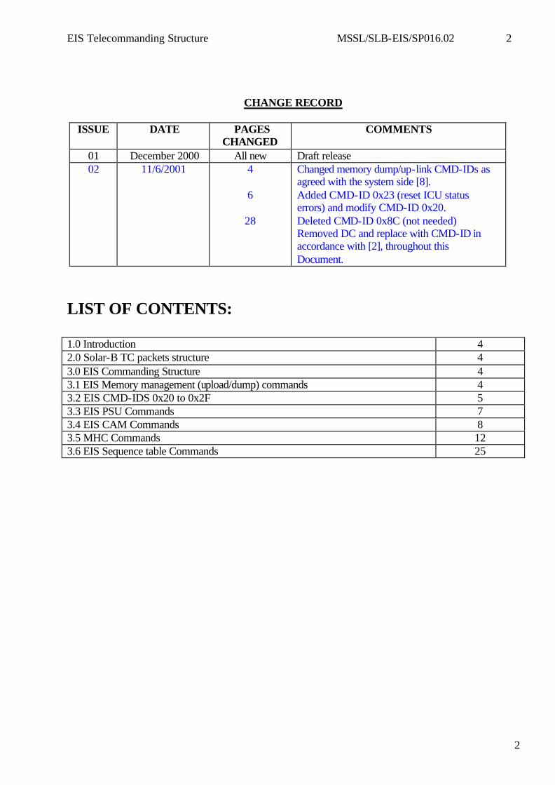
CHANGE RECORD
ISSUE DATE PAGES CHANGED
COMMENTS
01 December 2000 All new Draft release 02 11/6/2001 4
6
28
Changed memory dump/up-link CMD-IDs as agreed with the system side [8]. Added CMD-ID 0x23 (reset ICU status errors) and modify CMD-ID 0x20. Deleted CMD-ID 0x8C (not needed) Removed DC and replace with CMD-ID in accordance with [2], throughout this Document.
LIST OF CONTENTS: 1.0 Introduction 4 2.0 Solar-B TC packets structure 4 3.0 EIS Commanding Structure 4 3.1 EIS Memory management (upload/dump) commands 4 3.2 EIS CMD-IDS 0x20 to 0x2F 5 3.3 EIS PSU Commands 7 3.4 EIS CAM Commands 8 3.5 MHC Commands 12 3.6 EIS Sequence table Commands 25
EIS Telecommanding Structure MSSL/SLB-EIS/SP016.02 3
3
Glossary and Convention: AE Camera Analogue Electronics AEC Automatic Exposure Controller BC Block Command, Solar-B Command parameter CAL Calibration CAM Camera CMD-ID EIS command identifier (BC1) DC Discrete Command (Solar-B spacecraft command header) EIS Extreme-ultraviolet Imaging Spectrometer GRA Grating GSE Ground Support Equipment ICD Interface Control Document MHC Mechanism and Heater controller MMH MHC Message Header N/A Not Applicable OCB On Chip Binning (CAM function) P Parameter (equivalent to BC(s)) PID Power, Current and Delta MHC heater control Reg. Register PSU Power Supply Unit ROE Camera Read-out Electronics SLA Slit/slot subassembly and includes the shutter SS Slit/slot mechanism VOD CCD Voltage Output Drain VRD CCD Voltage Reset Drain QCM Quartz Crystal Microbalance (contamination monitor). Applicable references: These references appears in [ ] brackets in this document. 1 – EIS Science requirements: MSSL/SLB-EIS/SP007.01 2 – MDP ICU interface document: NAO/SLB-EIS/SP/MDP001.02 3 – EIS Mode definition: MSSL/SLB-EIS/SP0013.01 4 – MHC S/W ICD (ICU-MHC), V6 5 – CAM Commanding and HK. Email from K. Rees on the 16th Nov. 2000 6 – PSU Commanding and HK. Email from A. McCalden on the 17th Nov. 2000 7 – EIS Status: MSSL/SLB EIS/SP17.02 8 – Working meeting at MSSL with ISAS/NAO between 26-28/03/2001.
EIS Telecommanding Structure MSSL/SLB-EIS/SP016.02 4
4
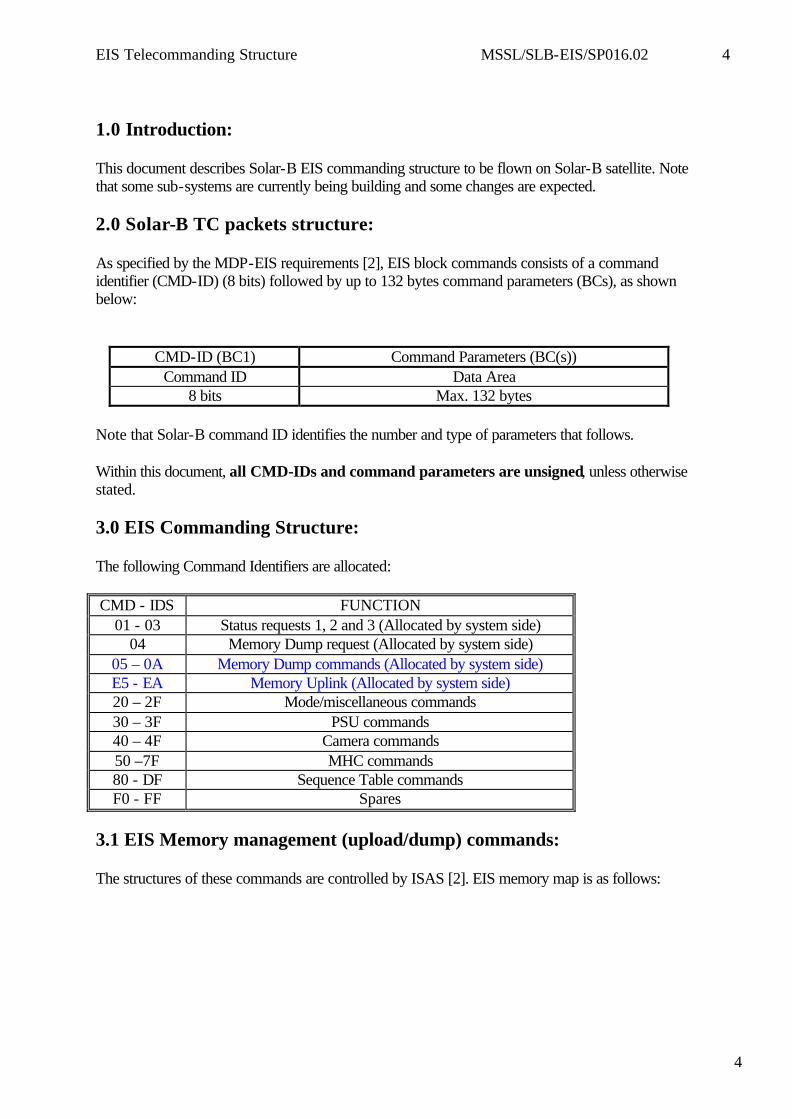
1.0 Introduction: This document describes Solar-B EIS commanding structure to be flown on Solar-B satellite. Note that some sub-systems are currently being building and some changes are expected. 2.0 Solar-B TC packets structure: As specified by the MDP-EIS requirements [2], EIS block commands consists of a command identifier (CMD-ID) (8 bits) followed by up to 132 bytes command parameters (BCs), as shown below:
CMD-ID (BC1) Command Parameters (BC(s)) Command ID Data Area
8 bits Max. 132 bytes Note that Solar-B command ID identifies the number and type of parameters that follows. Within this document, all CMD-IDs and command parameters are unsigned, unless otherwise stated. 3.0 EIS Commanding Structure: The following Command Identifiers are allocated: CMD - IDS FUNCTION
01 - 03 Status requests 1, 2 and 3 (Allocated by system side) 04 Memory Dump request (Allocated by system side)
05 – 0A Memory Dump commands (Allocated by system side) E5 - EA Memory Uplink (Allocated by system side) 20 – 2F Mode/miscellaneous commands 30 – 3F PSU commands 40 – 4F Camera commands 50 –7F MHC commands 80 - DF Sequence Table commands F0 - FF Spares
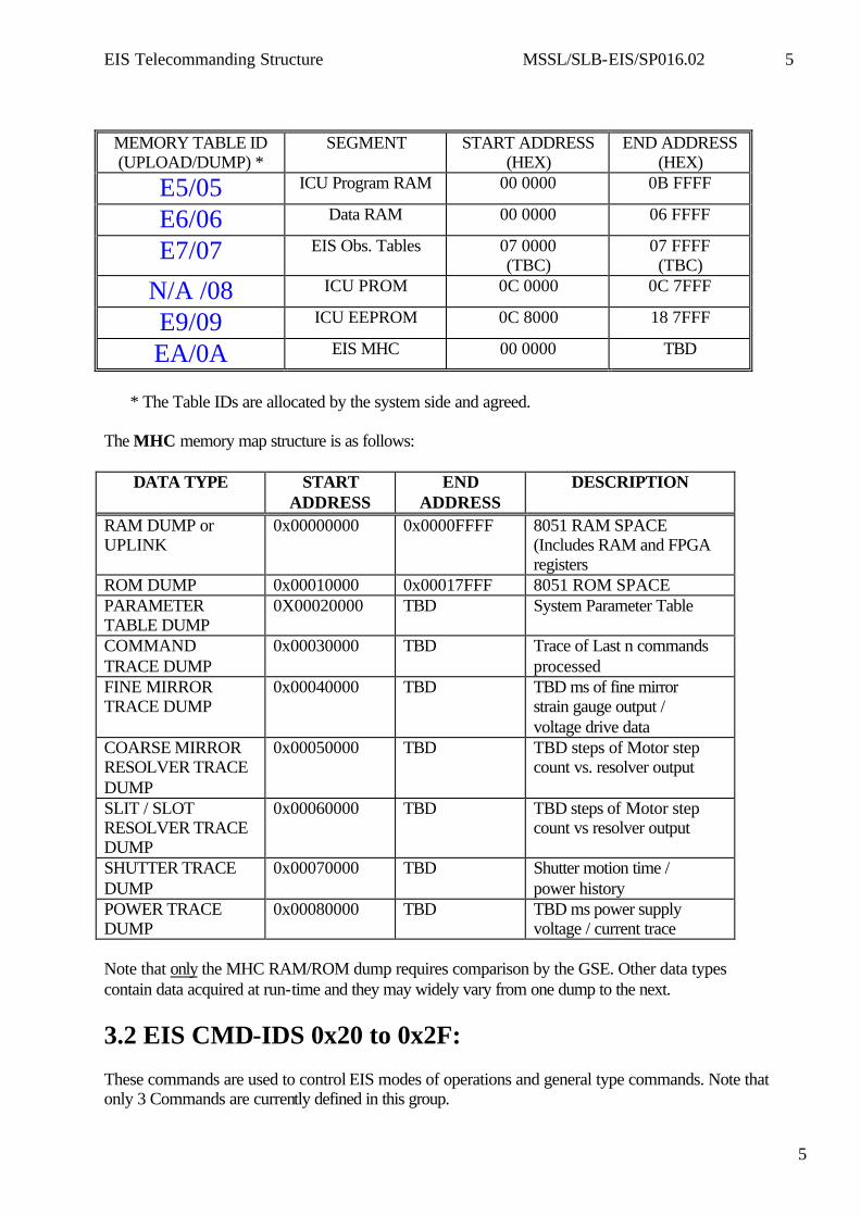
3.1 EIS Memory management (upload/dump) commands: The structures of these commands are controlled by ISAS [2]. EIS memory map is as follows:
EIS Telecommanding Structure MSSL/SLB-EIS/SP016.02 5
5
MEMORY TABLE ID (UPLOAD/DUMP) *
SEGMENT START ADDRESS (HEX)
END ADDRESS (HEX)
E5/05 ICU Program RAM 00 0000 0B FFFF
E6/06 Data RAM 00 0000 06 FFFF
E7/07 EIS Obs. Tables 07 0000 (TBC)
07 FFFF (TBC)
N/A /08 ICU PROM 0C 0000 0C 7FFF
E9/09 ICU EEPROM 0C 8000 18 7FFF
EA/0A EIS MHC 00 0000 TBD
* The Table IDs are allocated by the system side and agreed.
The MHC memory map structure is as follows:
DATA TYPE START ADDRESS
END ADDRESS
DESCRIPTION
RAM DUMP or UPLINK
0x00000000 0x0000FFFF 8051 RAM SPACE (Includes RAM and FPGA registers
ROM DUMP 0x00010000 0x00017FFF 8051 ROM SPACE PARAMETER TABLE DUMP
0X00020000 TBD System Parameter Table
COMMAND TRACE DUMP
0x00030000 TBD Trace of Last n commands processed
FINE MIRROR TRACE DUMP
0x00040000 TBD TBD ms of fine mirror strain gauge output / voltage drive data
COARSE MIRROR RESOLVER TRACE DUMP
0x00050000 TBD TBD steps of Motor step count vs. resolver output
SLIT / SLOT RESOLVER TRACE DUMP
0x00060000 TBD TBD steps of Motor step count vs resolver output
SHUTTER TRACE DUMP
0x00070000 TBD Shutter motion time / power history
POWER TRACE DUMP
0x00080000 TBD TBD ms power supply voltage / current trace
Note that only the MHC RAM/ROM dump requires comparison by the GSE. Other data types contain data acquired at run-time and they may widely vary from one dump to the next.
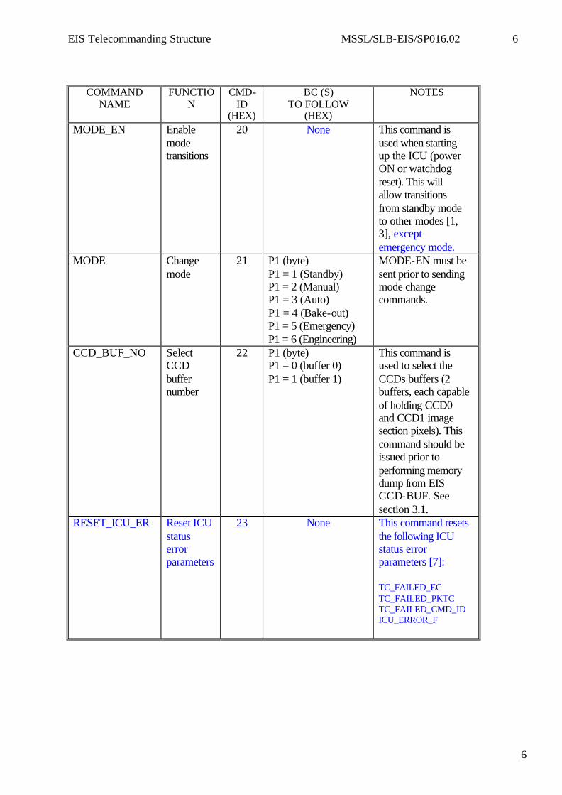
3.2 EIS CMD-IDS 0x20 to 0x2F: These commands are used to control EIS modes of operations and general type commands. Note that only 3 Commands are currently defined in this group.
EIS Telecommanding Structure MSSL/SLB-EIS/SP016.02 6
6
COMMAND NAME
FUNCTION
CMD-ID
(HEX)
BC (S) TO FOLLOW
(HEX)
NOTES
MODE_EN Enable mode transitions
20 None This command is used when starting up the ICU (power ON or watchdog reset). This will allow transitions from standby mode to other modes [1, 3], except emergency mode.
MODE Change mode
21 P1 (byte) P1 = 1 (Standby) P1 = 2 (Manual) P1 = 3 (Auto) P1 = 4 (Bake-out) P1 = 5 (Emergency) P1 = 6 (Engineering)
MODE-EN must be sent prior to sending mode change commands.
CCD_BUF_NO Select CCD buffer number
22 P1 (byte) P1 = 0 (buffer 0) P1 = 1 (buffer 1)
This command is used to select the CCDs buffers (2 buffers, each capable of holding CCD0 and CCD1 image section pixels). This command should be issued prior to performing memory dump from EIS CCD-BUF. See section 3.1.
RESET_ICU_ER Reset ICU status error parameters
23 None This command resets the following ICU status error parameters [7]: TC_FAILED_EC TC_FAILED_PKTC TC_FAILED_CMD_ID ICU_ERROR_F
EIS Telecommanding Structure MSSL/SLB-EIS/SP016.02 7
7
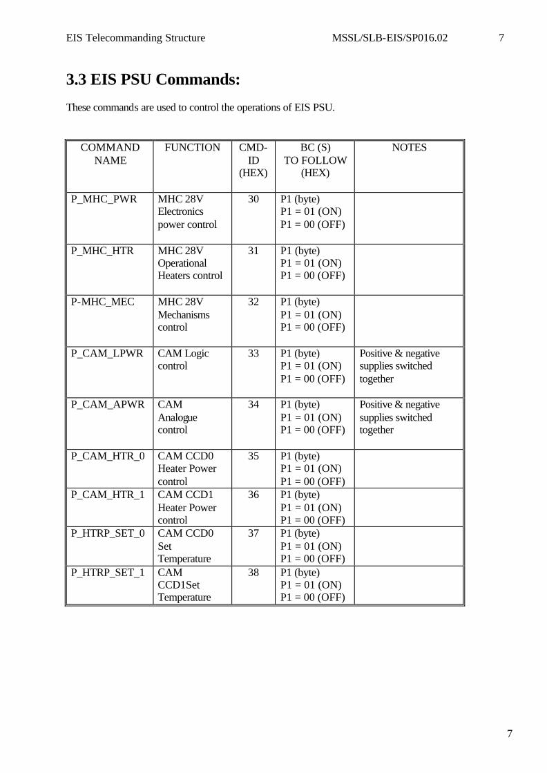
3.3 EIS PSU Commands: These commands are used to control the operations of EIS PSU.
COMMAND NAME
FUNCTION CMD-ID
(HEX)
BC (S) TO FOLLOW
(HEX)
NOTES
P_MHC_PWR MHC 28V Electronics power control
30 P1 (byte) P1 = 01 (ON) P1 = 00 (OFF)
P_MHC_HTR MHC 28V Operational Heaters control
31 P1 (byte) P1 = 01 (ON) P1 = 00 (OFF)
P-MHC_MEC MHC 28V Mechanisms control
32 P1 (byte) P1 = 01 (ON) P1 = 00 (OFF)
P_CAM_LPWR CAM Logic control
33 P1 (byte) P1 = 01 (ON) P1 = 00 (OFF)
Positive & negative supplies switched together
P_CAM_APWR CAM Analogue control
34 P1 (byte) P1 = 01 (ON) P1 = 00 (OFF)
Positive & negative supplies switched together
P_CAM_HTR_0 CAM CCD0 Heater Power control
35 P1 (byte) P1 = 01 (ON) P1 = 00 (OFF)
P_CAM_HTR_1 CAM CCD1 Heater Power control
36 P1 (byte) P1 = 01 (ON) P1 = 00 (OFF)
P_HTRP_SET_0 CAM CCD0 Set Temperature
37 P1 (byte) P1 = 01 (ON) P1 = 00 (OFF)
P_HTRP_SET_1 CAM CCD1Set Temperature
38 P1 (byte) P1 = 01 (ON) P1 = 00 (OFF)
EIS Telecommanding Structure MSSL/SLB-EIS/SP016.02 8
8
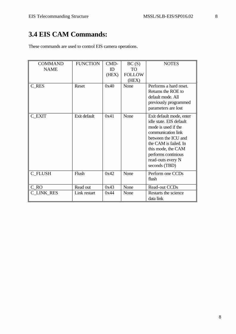
3.4 EIS CAM Commands: These commands are used to control EIS camera operations.
COMMAND NAME
FUNCTION CMD-ID
(HEX)
BC (S) TO
FOLLOW (HEX)
NOTES
C_RES Reset 0x40 None Performs a hard reset. Returns the ROE to default mode. All previously programmed parameters are lost
C_EXIT Exit default 0x41 None Exit default mode, enter idle state. EIS default mode is used if the communication link between the ICU and the CAM is failed. In this mode, the CAM performs continious read-outs every N seconds (TBD)
C_FLUSH Flush 0x42 None Perform one CCDs flush
C_RO Read out 0x43 None Read-out CCDs C_LINK_RES Link restart 0x44 None Restarts the science
data link
EIS Telecommanding Structure MSSL/SLB-EIS/SP016.02 9
9
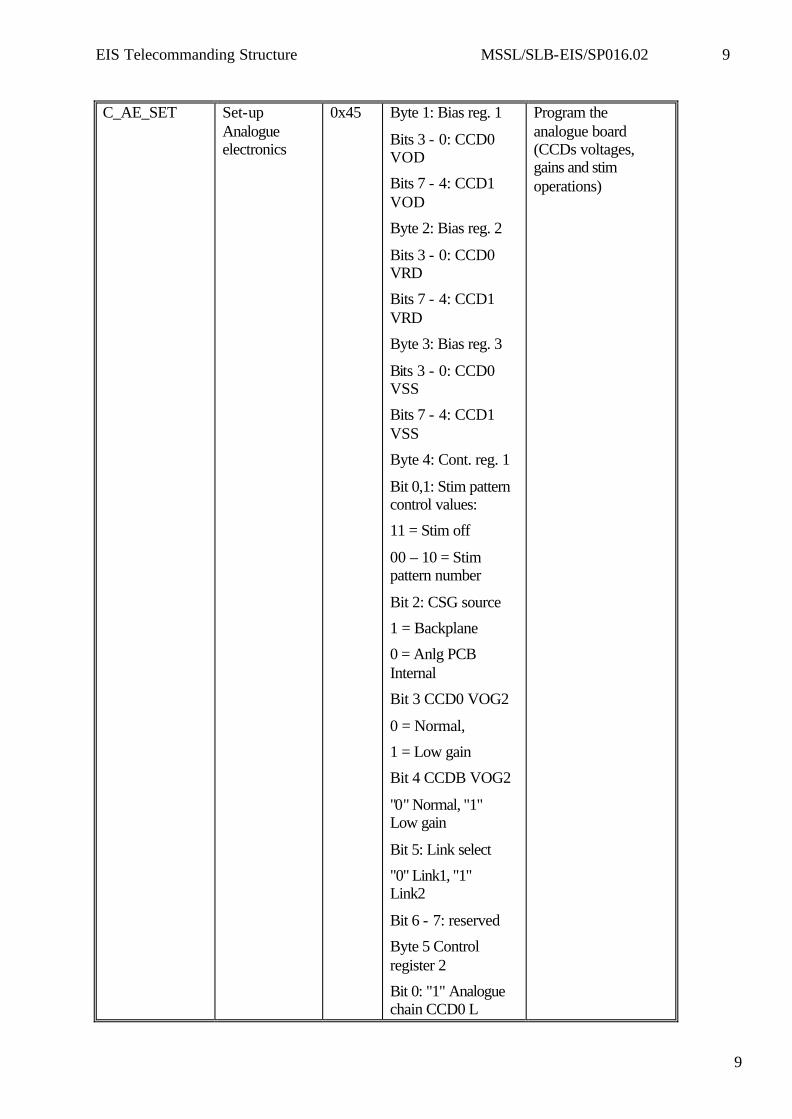
C_AE_SET Set-up
Analogue electronics
0x45 Byte 1: Bias reg. 1
Bits 3 - 0: CCD0 VOD
Bits 7 - 4: CCD1 VOD
Byte 2: Bias reg. 2
Bits 3 - 0: CCD0 VRD
Bits 7 - 4: CCD1 VRD
Byte 3: Bias reg. 3
Bits 3 - 0: CCD0 VSS
Bits 7 - 4: CCD1 VSS
Byte 4: Cont. reg. 1
Bit 0,1: Stim pattern control values:
11 = Stim off
00 – 10 = Stim pattern number
Bit 2: CSG source
1 = Backplane
0 = Anlg PCB Internal
Bit 3 CCD0 VOG2
0 = Normal,
1 = Low gain
Bit 4 CCDB VOG2
"0" Normal, "1" Low gain
Bit 5: Link select
"0" Link1, "1" Link2
Bit 6 - 7: reserved
Byte 5 Control register 2
Bit 0: "1" Analogue chain CCD0 L
Program the analogue board (CCDs voltages, gains and stim operations)
EIS Telecommanding Structure MSSL/SLB-EIS/SP016.02 10
10
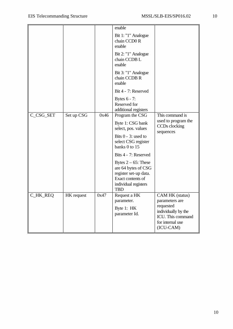
enable
Bit 1: "1" Analogue chain CCD0 R enable
Bit 2: "1" Analogue chain CCDB L enable
Bit 3: "1" Analogue chain CCDB R enable
Bit 4 - 7: Reserved
Bytes 6 - 7: Reserved for additional registers
C_CSG_SET Set up CSG 0x46 Program the CSG
Byte 1: CSG bank select, pos. values
Bits 0 - 3: used to select CSG register banks 0 to 15
Bits 4 - 7: Reserved
Bytes 2 – 65: These are 64 bytes of CSG register set-up data. Exact contents of individual registers TBD
This command is used to program the CCDs clocking sequences
C_HK_REQ HK request 0x47 Request a HK parameter.
Byte 1: HK parameter Id.
CAM HK (status) parameters are requested individually by the ICU. This command for internal use (ICU-CAM)
EIS Telecommanding Structure MSSL/SLB-EIS/SP016.02 11
11
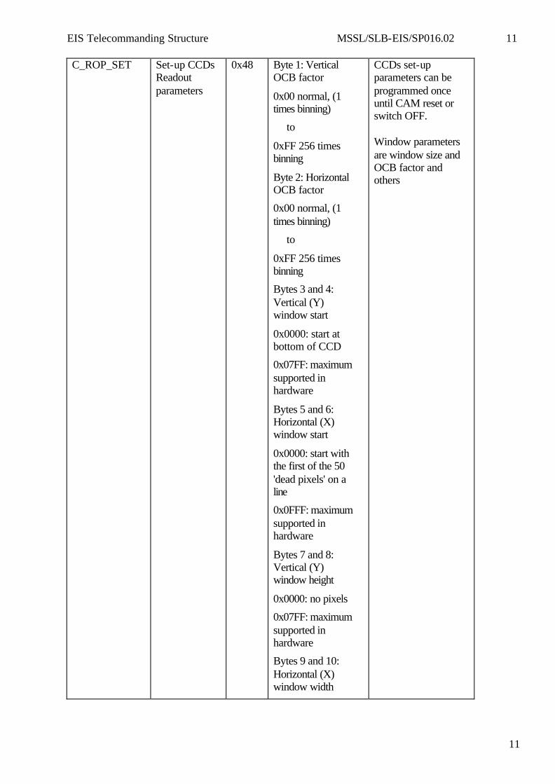
C_ROP_SET Set-up CCDs Readout parameters
0x48 Byte 1: Vertical OCB factor
0x00 normal, (1 times binning)
to
0xFF 256 times binning
Byte 2: Horizontal OCB factor
0x00 normal, (1 times binning)
to
0xFF 256 times binning
Bytes 3 and 4: Vertical (Y) window start
0x0000: start at bottom of CCD
0x07FF: maximum supported in hardware
Bytes 5 and 6: Horizontal (X) window start
0x0000: start with the first of the 50 'dead pixels' on a line
0x0FFF: maximum supported in hardware
Bytes 7 and 8: Vertical (Y) window height
0x0000: no pixels
0x07FF: maximum supported in hardware
Bytes 9 and 10: Horizontal (X) window width
CCDs set-up parameters can be programmed once until CAM reset or switch OFF. Window parameters are window size and OCB factor and others
EIS Telecommanding Structure MSSL/SLB-EIS/SP016.02 12
12
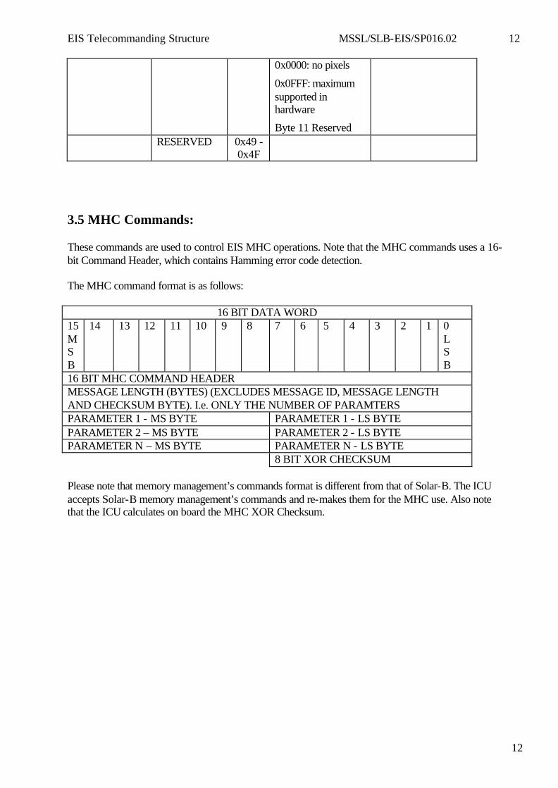
0x0000: no pixels
0x0FFF: maximum supported in hardware
Byte 11 Reserved RESERVED 0x49 -
0x4F
3.5 MHC Commands: These commands are used to control EIS MHC operations. Note that the MHC commands uses a 16-bit Command Header, which contains Hamming error code detection. The MHC command format is as follows:
16 BIT DATA WORD 15 MSB
14 13 12 11 10 9 8 7 6 5 4 3 2 1 0 L S B
16 BIT MHC COMMAND HEADER MESSAGE LENGTH (BYTES) (EXCLUDES MESSAGE ID, MESSAGE LENGTH AND CHECKSUM BYTE). I.e. ONLY THE NUMBER OF PARAMTERS PARAMETER 1 - MS BYTE PARAMETER 1 - LS BYTE PARAMETER 2 – MS BYTE PARAMETER 2 - LS BYTE PARAMETER N – MS BYTE PARAMETER N - LS BYTE 8 BIT XOR CHECKSUM Please note that memory management’s commands format is different from that of Solar-B. The ICU accepts Solar-B memory management’s commands and re-makes them for the MHC use. Also note that the ICU calculates on board the MHC XOR Checksum.
EIS Telecommanding Structure MSSL/SLB-EIS/SP016.02 13
13
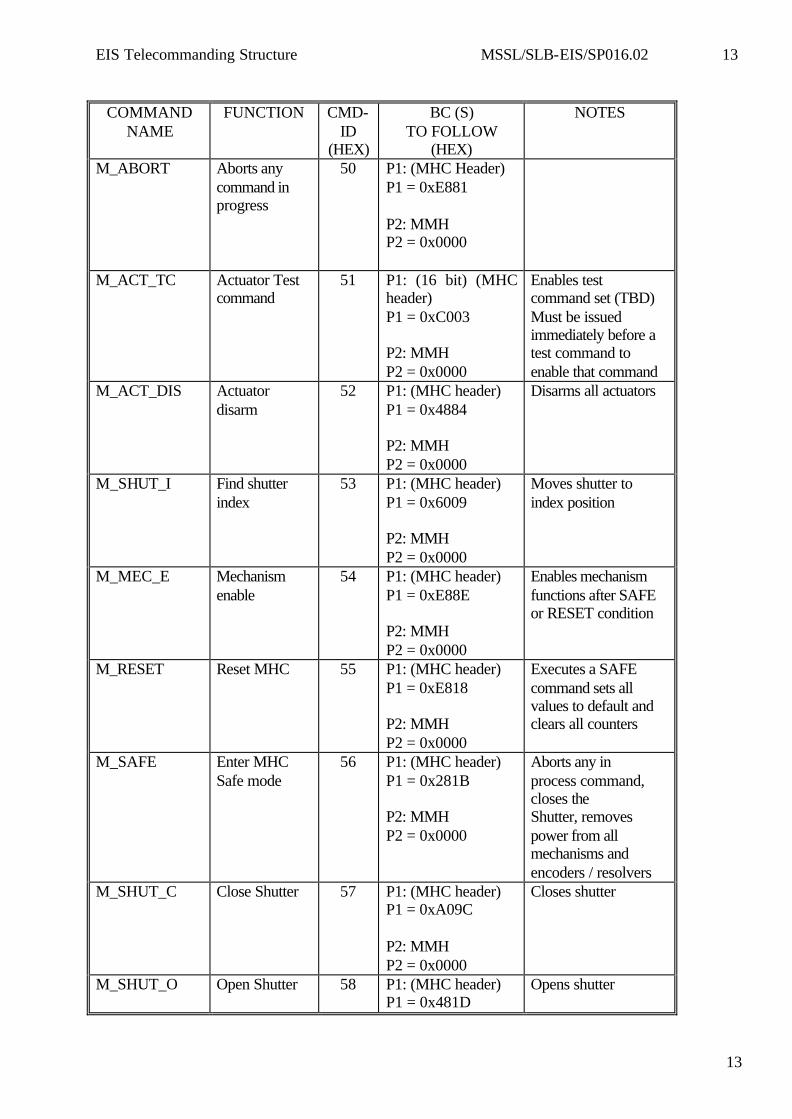
COMMAND
NAME FUNCTION CMD-
ID (HEX)
BC (S) TO FOLLOW
(HEX)
NOTES
M_ABORT Aborts any command in progress
50 P1: (MHC Header) P1 = 0xE881 P2: MMH P2 = 0x0000
M_ACT_TC Actuator Test command
51 P1: (16 bit) (MHC header) P1 = 0xC003 P2: MMH P2 = 0x0000
Enables test command set (TBD) Must be issued immediately before a test command to enable that command
M_ACT_DIS Actuator disarm
52 P1: (MHC header) P1 = 0x4884 P2: MMH P2 = 0x0000
Disarms all actuators
M_SHUT_I Find shutter index
53 P1: (MHC header) P1 = 0x6009 P2: MMH P2 = 0x0000
Moves shutter to index position
M_MEC_E Mechanism enable
54 P1: (MHC header) P1 = 0xE88E P2: MMH P2 = 0x0000
Enables mechanism functions after SAFE or RESET condition
M_RESET Reset MHC 55 P1: (MHC header) P1 = 0xE818 P2: MMH P2 = 0x0000
Executes a SAFE command sets all values to default and clears all counters
M_SAFE Enter MHC Safe mode
56 P1: (MHC header) P1 = 0x281B P2: MMH P2 = 0x0000
Aborts any in process command, closes the Shutter, removes power from all mechanisms and encoders / resolvers
M_SHUT_C Close Shutter 57 P1: (MHC header) P1 = 0xA09C P2: MMH P2 = 0x0000
Closes shutter
M_SHUT_O Open Shutter 58 P1: (MHC header) P1 = 0x481D
Opens shutter
EIS Telecommanding Structure MSSL/SLB-EIS/SP016.02 14
14
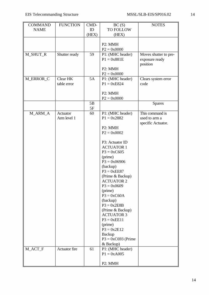
COMMAND NAME
FUNCTION CMD-ID
(HEX)
BC (S) TO FOLLOW
(HEX)
NOTES
P2: MMH P2 = 0x0000
M_SHUT_R Shutter ready 59 P1: (MHC header) P1 = 0x881E P2: MMH P2 = 0x0000
Moves shutter to pre-exposure ready position
M_ERROR_C Clear HK table error
5A P1: (MHC header) P1 = 0xE824 P2: MMH P2 = 0x0000
Clears system error code
5B 5F
Spares
M_ARM_A Actuator Arm level 1
60 P1: (MHC header) P1 = 0x2882 P2: MMH P2 = 0x0002 P3: Actuator ID ACTUATOR 1 P3 = 0xC605 (prime) P3 = 0x06906 (backup) P3 = 0xEE87 (Prime & Backup) ACTUATOR 2 P3 = 0x0609 (prime) P3 = 0xC60A (backup) P3 = 0x2E8B (Prime & Backup) ACTUATOR 3 P3 = 0xEE11 (prime) P3 = 0x2E12 Backup P3 = 0xC693 (Prime & Backup)
This command is used to arm a specific Actuator.
M_ACT_F Actuator fire 61 P1: (MHC header) P1 = 0xA005 P2: MMH
EIS Telecommanding Structure MSSL/SLB-EIS/SP016.02 15
15
COMMAND NAME
FUNCTION CMD-ID
(HEX)
BC (S) TO FOLLOW
(HEX)
NOTES
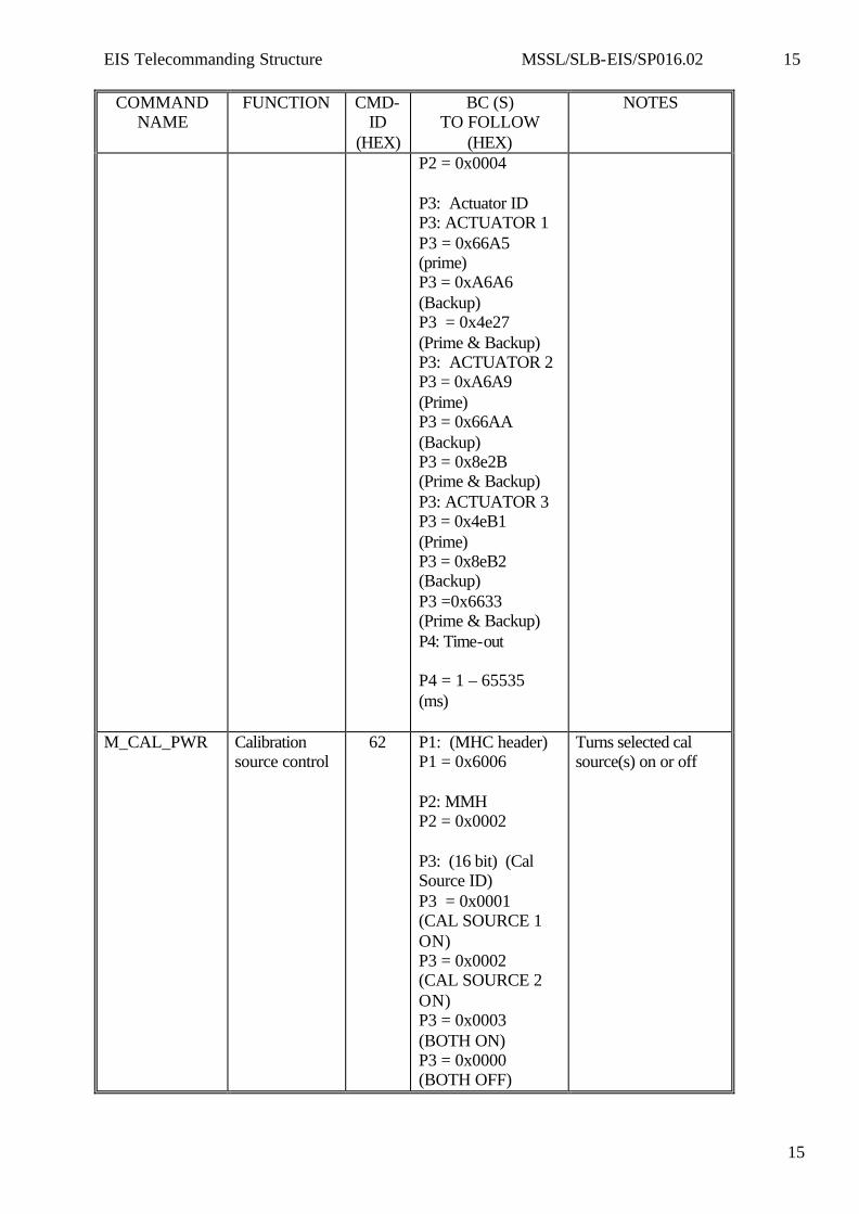
P2 = 0x0004 P3: Actuator ID P3: ACTUATOR 1 P3 = 0x66A5 (prime) P3 = 0xA6A6 (Backup) P3 = 0x4e27 (Prime & Backup) P3: ACTUATOR 2 P3 = 0xA6A9 (Prime) P3 = 0x66AA (Backup) P3 = 0x8e2B (Prime & Backup) P3: ACTUATOR 3 P3 = 0x4eB1 (Prime) P3 = 0x8eB2 (Backup) P3 =0x6633 (Prime & Backup) P4: Time-out P4 = 1 – 65535 (ms)
M_CAL_PWR Calibration source control
62 P1: (MHC header) P1 = 0x6006 P2: MMH P2 = 0x0002 P3: (16 bit) (Cal Source ID) P3 = 0x0001 (CAL SOURCE 1 ON) P3 = 0x0002 (CAL SOURCE 2 ON) P3 = 0x0003 (BOTH ON) P3 = 0x0000 (BOTH OFF)
Turns selected cal source(s) on or off

EIS Telecommanding Structure MSSL/SLB-EIS/SP016.02 16
16
COMMAND NAME
FUNCTION CMD-ID
(HEX)
BC (S) TO FOLLOW
(HEX)
NOTES
M_GRA_I Find grating index
63 P1: (MHC header) P1 = 0x8888 P2: MMH P2 = 0x0002 P3: Index position P3 = 0x0010 (lower index) P3 = 0x0020 (middle index) P3 = 0x0040 (upper index)
Moves GRA motor to selected index
M_GRA_MAN GRA. Manual 64 P1: (MHC header) P1 = 0xA00A P2: MMH P2 = 0x000E P3: DIRECTION P3 = 0x0001 (FORWARD) P3 = 0xFFFF (REVERSE) P4: STEP TIME P4 = 1 – 65535 ms / step P5: STEP DRIVE TIME P5 = 1 – 65535 ms / step P6: STEPS_1 P6 = 0 – 65535 steps P7: ENCODER INDEX P7 = 0x0010 lower limit P7 = 0x0020 (midpoint) P7 = 0x0040 upper limit P7 = 0xFFFF
Move grating focus motor in (DIRECTION) at (STEP TIME) and with a (STEP DRIVE TIME) for (STEPS_1), if (STEPS_1 = 0) then move to (ENCODER_INDEX) then stop after (STEPS_2) then hold for (HOLD_TIME); last phase on. Stop if total steps >= (GRA_MAX_STEPS) or time > GRA_MAX_RUN_TIME or if ENCODER_INDEX = +/- limit. Prohibit movement beyond +/- limit.
EIS Telecommanding Structure MSSL/SLB-EIS/SP016.02 17
17
COMMAND NAME
FUNCTION CMD-ID
(HEX)
BC (S) TO FOLLOW
(HEX)
NOTES
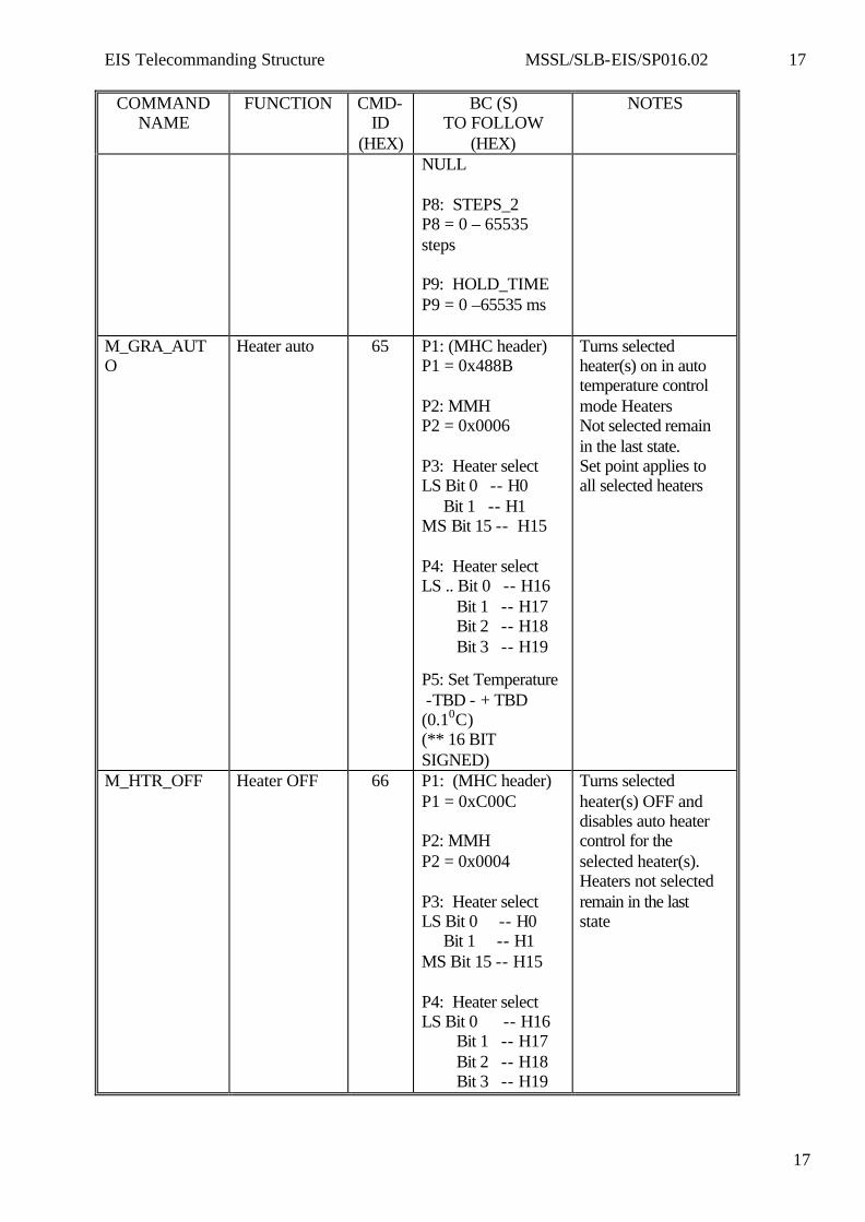
NULL P8: STEPS_2 P8 = 0 – 65535 steps P9: HOLD_TIME P9 = 0 –65535 ms
M_GRA_AUTO
Heater auto 65 P1: (MHC header) P1 = 0x488B P2: MMH P2 = 0x0006 P3: Heater select LS Bit 0 -- H0 Bit 1 -- H1 MS Bit 15 -- H15 P4: Heater select LS .. Bit 0 -- H16 Bit 1 -- H17 Bit 2 -- H18 Bit 3 -- H19 P5: Set Temperature -TBD - + TBD (0.10C) (** 16 BIT SIGNED)
Turns selected heater(s) on in auto temperature control mode Heaters Not selected remain in the last state. Set point applies to all selected heaters
M_HTR_OFF Heater OFF 66 P1: (MHC header) P1 = 0xC00C P2: MMH P2 = 0x0004 P3: Heater select LS Bit 0 -- H0 Bit 1 -- H1 MS Bit 15 -- H15 P4: Heater select LS Bit 0 -- H16 Bit 1 -- H17 Bit 2 -- H18 Bit 3 -- H19
Turns selected heater(s) OFF and disables auto heater control for the selected heater(s). Heaters not selected remain in the last state
EIS Telecommanding Structure MSSL/SLB-EIS/SP016.02 18
18
COMMAND NAME
FUNCTION CMD-ID
(HEX)
BC (S) TO FOLLOW
(HEX)
NOTES
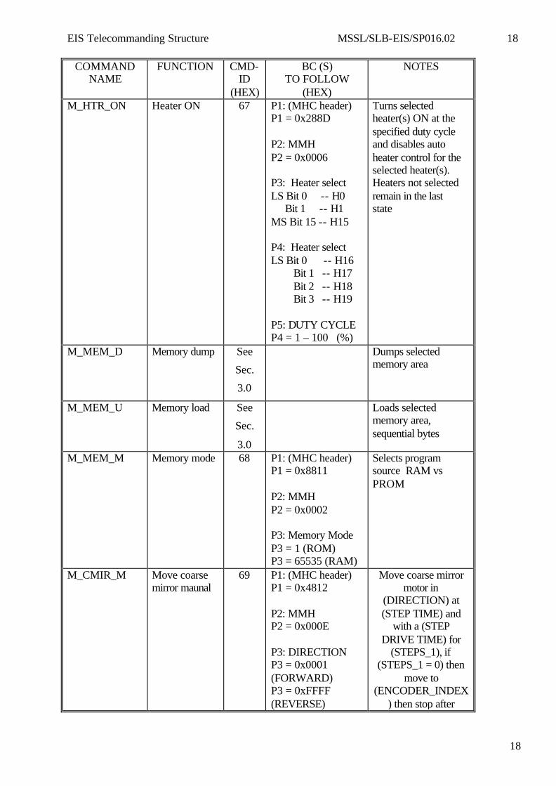
M_HTR_ON Heater ON 67 P1: (MHC header) P1 = 0x288D P2: MMH P2 = 0x0006 P3: Heater select LS Bit 0 -- H0 Bit 1 -- H1 MS Bit 15 -- H15 P4: Heater select LS Bit 0 -- H16 Bit 1 -- H17 Bit 2 -- H18 Bit 3 -- H19 P5: DUTY CYCLE P4 = 1 – 100 (%)
Turns selected heater(s) ON at the specified duty cycle and disables auto heater control for the selected heater(s). Heaters not selected remain in the last state
M_MEM_D Memory dump See
Sec.
3.0
Dumps selected memory area
M_MEM_U Memory load See
Sec.
3.0
Loads selected memory area, sequential bytes
M_MEM_M Memory mode 68 P1: (MHC header) P1 = 0x8811 P2: MMH P2 = 0x0002 P3: Memory Mode P3 = 1 (ROM) P3 = 65535 (RAM)
Selects program source RAM vs PROM
M_CMIR_M Move coarse mirror maunal
69 P1: (MHC header) P1 = 0x4812 P2: MMH P2 = 0x000E P3: DIRECTION P3 = 0x0001 (FORWARD) P3 = 0xFFFF (REVERSE)
Move coarse mirror motor in
(DIRECTION) at (STEP TIME) and
with a (STEP DRIVE TIME) for
(STEPS_1), if (STEPS_1 = 0) then
move to (ENCODER_INDEX
) then stop after
EIS Telecommanding Structure MSSL/SLB-EIS/SP016.02 19
19
COMMAND NAME
FUNCTION CMD-ID
(HEX)
BC (S) TO FOLLOW
(HEX)
NOTES
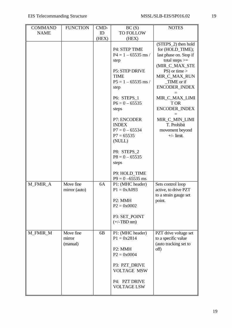
P4: STEP TIME P4 = 1 – 65535 ms / step P5: STEP DRIVE TIME P5 = 1 – 65535 ms / step P6: STEPS_1 P6 = 0 – 65535 steps P7: ENCODER INDEX P7 = 0 – 65534 P7 = 65535 (NULL) P8: STEPS_2 P8 = 0 – 65535 steps P9: HOLD_TIME P9 = 0 –65535 ms
(STEPS_2) then hold for (HOLD_TIME); last phase on. Stop if
total steps >= (MIR_C_MAX_STE
PS) or time > MIR_C_MAX_RUN
_TIME or if ENCODER_INDEX
= MIR_C_MAX_LIMI
T OR ENCODER_INDEX
= MIR_C_MIN_LIMI
T. Prohibit movement beyond
+/- limit.
M_FMIR_A Move fine mirror (auto)
6A P1: (MHC header) P1 = 0xA093 P2: MMH P2 = 0x0002 P3: SET_POINT (+/-TBD nm)
Sets control loop active, to drive PZT to a strain gauge set point.
M_FMIR_M Move fine mirror (manual)
6B P1: (MHC header) P1 = 0x2814 P2: MMH P2 = 0x0004 P3: PZT_DRIVE VOLTAGE MSW P4: PZT DRIVE VOLTAGE LSW
PZT drive voltage set to a specific value (auto tracking set to off)
EIS Telecommanding Structure MSSL/SLB-EIS/SP016.02 20
20
COMMAND NAME
FUNCTION CMD-ID
(HEX)
BC (S) TO FOLLOW
(HEX)
NOTES
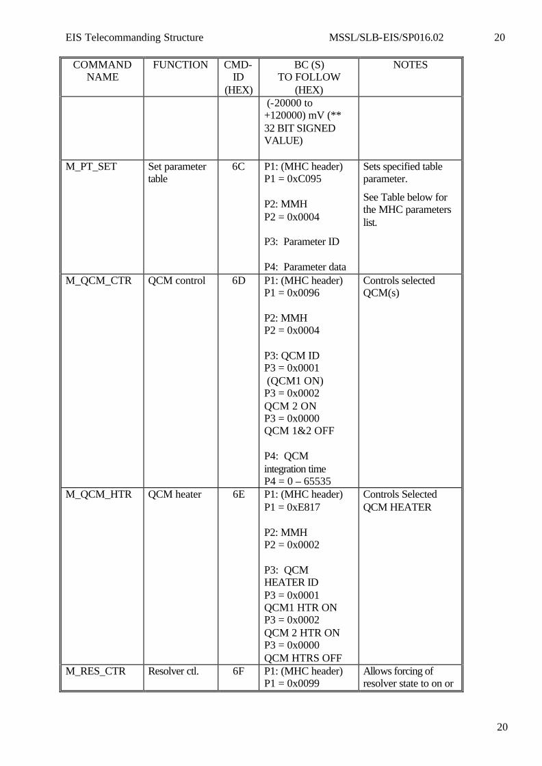
(-20000 to +120000) mV (** 32 BIT SIGNED VALUE)
M_PT_SET Set parameter table
6C P1: (MHC header) P1 = 0xC095 P2: MMH P2 = 0x0004 P3: Parameter ID P4: Parameter data
Sets specified table parameter.
See Table below for the MHC parameters list.
M_QCM_CTR QCM control 6D P1: (MHC header) P1 = 0x0096 P2: MMH P2 = 0x0004 P3: QCM ID P3 = 0x0001 (QCM1 ON) P3 = 0x0002 QCM 2 ON P3 = 0x0000 QCM 1&2 OFF P4: QCM integration time P4 = 0 – 65535
Controls selected QCM(s)
M_QCM_HTR QCM heater 6E P1: (MHC header) P1 = 0xE817 P2: MMH P2 = 0x0002 P3: QCM HEATER ID P3 = 0x0001 QCM1 HTR ON P3 = 0x0002 QCM 2 HTR ON P3 = 0x0000 QCM HTRS OFF
Controls Selected QCM HEATER
M_RES_CTR Resolver ctl. 6F P1: (MHC header) P1 = 0x0099
Allows forcing of resolver state to on or
EIS Telecommanding Structure MSSL/SLB-EIS/SP016.02 21
21
COMMAND NAME
FUNCTION CMD-ID
(HEX)
BC (S) TO FOLLOW
(HEX)
NOTES
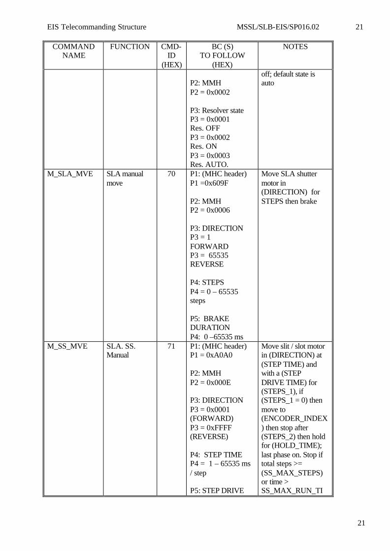
P2: MMH P2 = 0x0002 P3: Resolver state P3 = 0x0001 Res. OFF P3 = 0x0002 Res. ON P3 = 0x0003 Res. AUTO.
off; default state is auto
M_SLA_MVE SLA manual move
70 P1: (MHC header) P1 =0x609F P2: MMH P2 = 0x0006 P3: DIRECTION P3 = 1 FORWARD P3 = 65535 REVERSE P4: STEPS P4 = 0 – 65535 steps P5: BRAKE DURATION P4: 0 –65535 ms
Move SLA shutter motor in (DIRECTION) for STEPS then brake
M_SS_MVE SLA. SS. Manual
71 P1: (MHC header) P1 = 0xA0A0 P2: MMH P2 = 0x000E P3: DIRECTION P3 = 0x0001 (FORWARD) P3 = 0xFFFF (REVERSE) P4: STEP TIME P4 = 1 – 65535 ms / step P5: STEP DRIVE
Move slit / slot motor in (DIRECTION) at (STEP TIME) and with a (STEP DRIVE TIME) for (STEPS_1), if (STEPS_1 = 0) then move to (ENCODER_INDEX) then stop after (STEPS_2) then hold for (HOLD_TIME); last phase on. Stop if total steps >= (SS_MAX_STEPS) or time > SS_MAX_RUN_TI
EIS Telecommanding Structure MSSL/SLB-EIS/SP016.02 22
22
COMMAND NAME
FUNCTION CMD-ID
(HEX)
BC (S) TO FOLLOW
(HEX)
NOTES
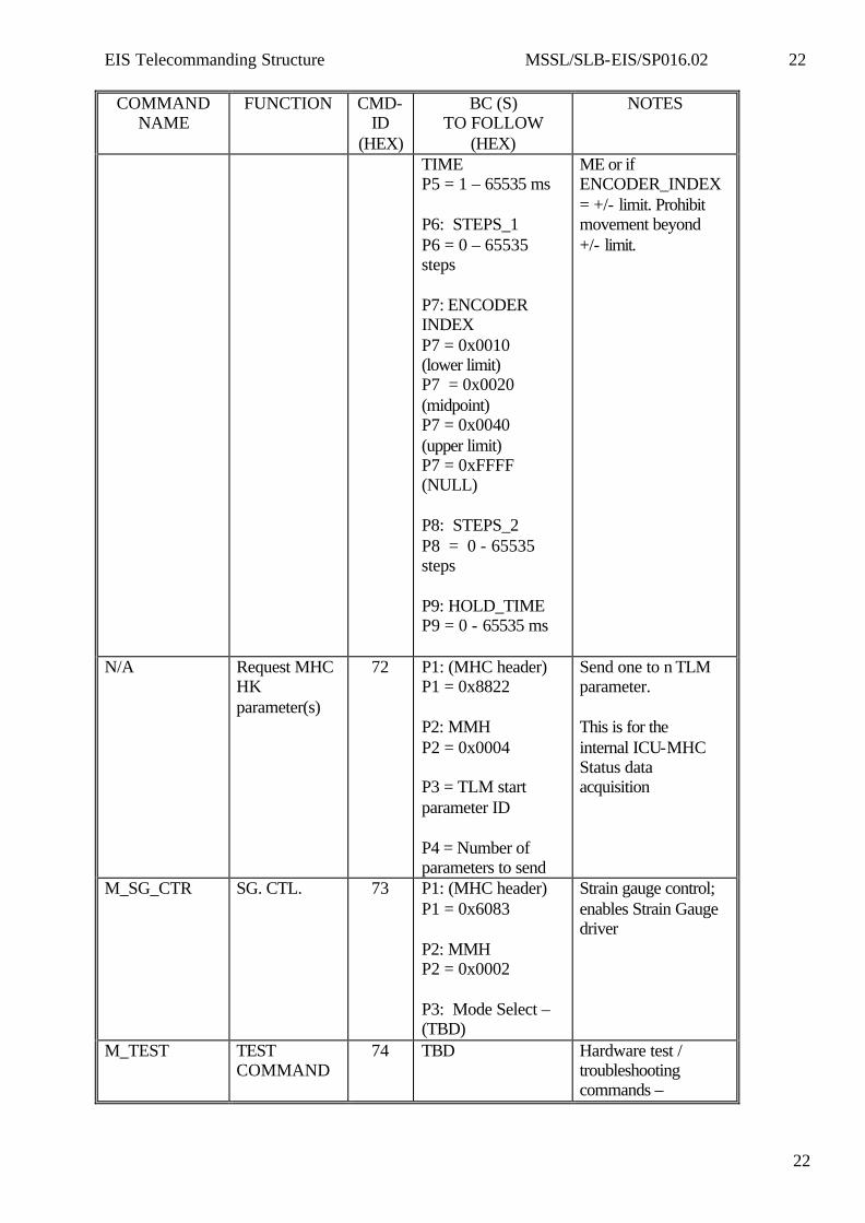
TIME P5 = 1 – 65535 ms P6: STEPS_1 P6 = 0 – 65535 steps P7: ENCODER INDEX P7 = 0x0010 (lower limit) P7 = 0x0020 (midpoint) P7 = 0x0040 (upper limit) P7 = 0xFFFF (NULL) P8: STEPS_2 P8 = 0 - 65535 steps P9: HOLD_TIME P9 = 0 - 65535 ms
ME or if ENCODER_INDEX = +/- limit. Prohibit movement beyond +/- limit.
N/A Request MHC HK parameter(s)
72 P1: (MHC header) P1 = 0x8822 P2: MMH P2 = 0x0004 P3 = TLM start parameter ID P4 = Number of parameters to send
Send one to n TLM parameter. This is for the internal ICU-MHC Status data acquisition
M_SG_CTR SG. CTL. 73 P1: (MHC header) P1 = 0x6083 P2: MMH P2 = 0x0002 P3: Mode Select – (TBD)
Strain gauge control; enables Strain Gauge driver
M_TEST TEST COMMAND
74 TBD Hardware test / troubleshooting commands –
EIS Telecommanding Structure MSSL/SLB-EIS/SP016.02 23
23
COMMAND NAME
FUNCTION CMD-ID
(HEX)
BC (S) TO FOLLOW
(HEX)
NOTES
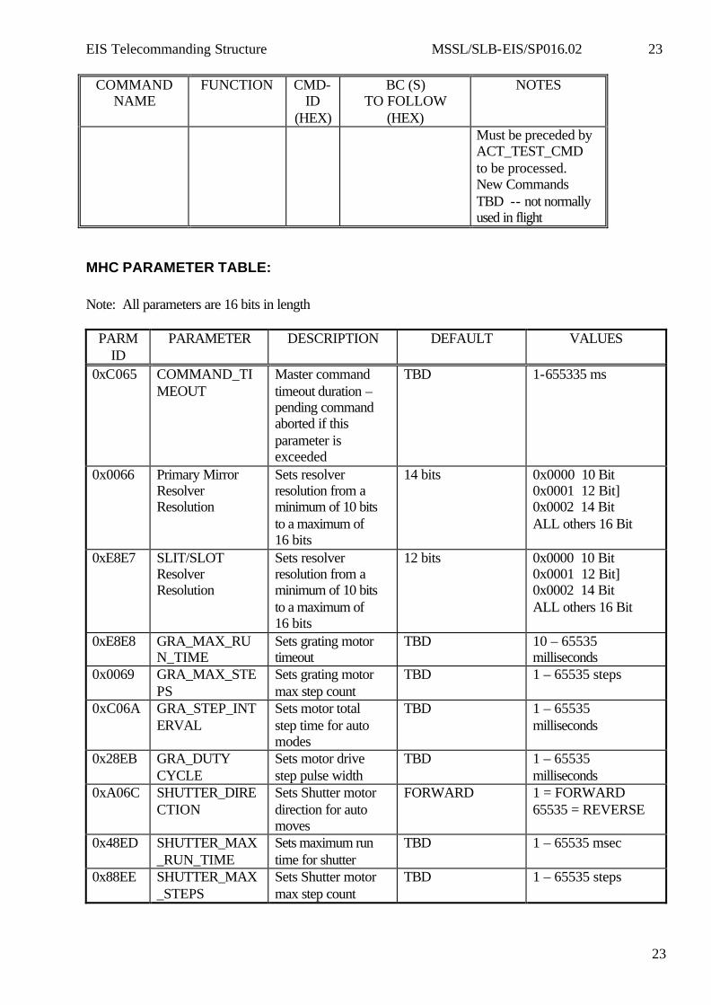
Must be preceded by ACT_TEST_CMD to be processed. New Commands TBD -- not normally used in flight
MHC PARAMETER TABLE: Note: All parameters are 16 bits in length
PARM ID
PARAMETER DESCRIPTION DEFAULT VALUES
0xC065 COMMAND_TIMEOUT
Master command timeout duration – pending command aborted if this parameter is exceeded
TBD 1-655335 ms
0x0066 Primary Mirror Resolver Resolution
Sets resolver resolution from a minimum of 10 bits to a maximum of 16 bits
14 bits 0x0000 10 Bit 0x0001 12 Bit] 0x0002 14 Bit ALL others 16 Bit
0xE8E7 SLIT/SLOT Resolver Resolution
Sets resolver resolution from a minimum of 10 bits to a maximum of 16 bits
12 bits 0x0000 10 Bit 0x0001 12 Bit] 0x0002 14 Bit ALL others 16 Bit
0xE8E8 GRA_MAX_RUN_TIME
Sets grating motor timeout
TBD 10 – 65535 milliseconds
0x0069 GRA_MAX_STEPS
Sets grating motor max step count
TBD 1 – 65535 steps
0xC06A GRA_STEP_INTERVAL
Sets motor total step time for auto modes
TBD 1 – 65535 milliseconds
0x28EB GRA_DUTY CYCLE
Sets motor drive step pulse width
TBD 1 – 65535 milliseconds
0xA06C SHUTTER_DIRECTION
Sets Shutter motor direction for auto moves
FORWARD 1 = FORWARD 65535 = REVERSE
0x48ED SHUTTER_MAX_RUN_TIME
Sets maximum run time for shutter
TBD 1 – 65535 msec
0x88EE SHUTTER_MAX_STEPS
Sets Shutter motor max step count
TBD 1 – 65535 steps
EIS Telecommanding Structure MSSL/SLB-EIS/SP016.02 24
24
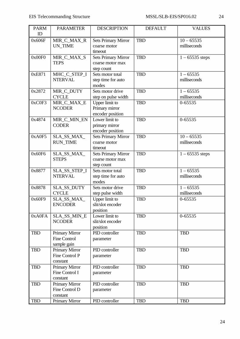
PARM ID
PARAMETER DESCRIPTION DEFAULT VALUES
0x606F MIR_C_MAX_RUN_TIME
Sets Primary Mirror coarse motor timeout
TBD 10 – 65535 milliseconds
0x00F0 MIR_C_MAX_STEPS
Sets Primary Mirror coarse motor max step count
TBD 1 – 65535 steps
0xE871 MHC_C_STEP_INTERVAL
Sets motor total step time for auto modes
TBD 1 – 65535 milliseconds
0x2872 MIR_C_DUTY CYCLE
Sets motor drive step on pulse width
TBD 1 – 65535 milliseconds
0xC0F3 MIR_C_MAX_ENCODER
Upper limit to Primary mirror encoder position
TBD 0-65535
0x4874 MIR_C_MIN_ENCODER
Lower limit to primary mirror encoder position
TBD 0-65535
0xA0F5 SLA_SS_MAX_RUN_TIME
Sets Primary Mirror coarse motor timeout
TBD 10 – 65535 milliseconds
0x60F6 SLA_SS_MAX_STEPS
Sets Primary Mirror coarse motor max step count
TBD 1 – 65535 steps
0x8877 SLA_SS_STEP_INTERVAL
Sets motor total step time for auto modes
TBD 1 – 65535 milliseconds
0x8878 SLA_SS_DUTY CYCLE
Sets motor drive step pulse width
TBD 1 – 65535 milliseconds
0x60F9 SLA_SS_MAX_ENCODER
Upper limit to slit/slot encoder position
TBD 0-65535
0xA0FA SLA_SS_MIN_ENCODER
Lower limit to slit/slot encoder position
TBD 0-65535
TBD Primary Mirror Fine Control sample gain
PID controller parameter
TBD TBD
TBD Primary Mirror Fine Control P constant
PID controller parameter
TBD TBD
TBD Primary Mirror Fine Control I constant
PID controller parameter
TBD TBD
TBD Primary Mirror Fine Control D constant
PID controller parameter
TBD TBD
TBD Primary Mirror PID controller TBD TBD
EIS Telecommanding Structure MSSL/SLB-EIS/SP016.02 25
25
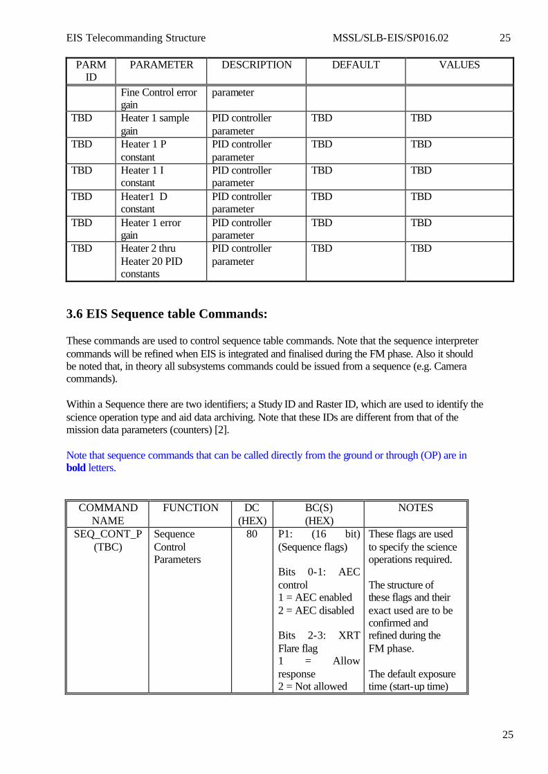
PARM ID
PARAMETER DESCRIPTION DEFAULT VALUES
Fine Control error gain
parameter
TBD Heater 1 sample gain
PID controller parameter
TBD TBD
TBD Heater 1 P constant
PID controller parameter
TBD TBD
TBD Heater 1 I constant
PID controller parameter
TBD TBD
TBD Heater1 D constant
PID controller parameter
TBD TBD
TBD Heater 1 error gain
PID controller parameter
TBD TBD
TBD Heater 2 thru Heater 20 PID constants
PID controller parameter
TBD TBD
3.6 EIS Sequence table Commands: These commands are used to control sequence table commands. Note that the sequence interpreter commands will be refined when EIS is integrated and finalised during the FM phase. Also it should be noted that, in theory all subsystems commands could be issued from a sequence (e.g. Camera commands). Within a Sequence there are two identifiers; a Study ID and Raster ID, which are used to identify the science operation type and aid data archiving. Note that these IDs are different from that of the mission data parameters (counters) [2]. Note that sequence commands that can be called directly from the ground or through (OP) are in bold letters.
COMMAND NAME
FUNCTION DC (HEX)
BC(S) (HEX)
NOTES
SEQ_CONT_P (TBC)
Sequence Control Parameters
80 P1: (16 bit) (Sequence flags) Bits 0-1: AEC control 1 = AEC enabled 2 = AEC disabled Bits 2-3: XRT Flare flag 1 = Allow response 2 = Not allowed
These flags are used to specify the science operations required. The structure of these flags and their exact used are to be confirmed and refined during the FM phase. The default exposure time (start-up time)
EIS Telecommanding Structure MSSL/SLB-EIS/SP016.02 26
26
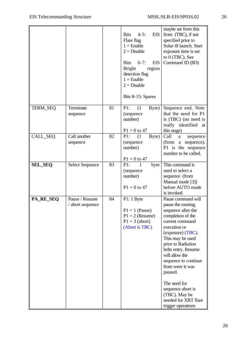
Bits 4-5: EIS Flare flag 1 = Enable 2 = Disable Bits 6-7: EIS Bright region detection flag 1 = Enable 2 = Disable Bits 8-15: Spares
maybe set from this from (TBC), if not specified prior to Solar-B launch. Start exposure time is set to 0 (TBC). See Command ID (8D)
TERM_SEQ Terminate sequence
81 P1: (1 Byte) (sequence number) P1 = 0 to 47
Sequence end. Note that the need for P1 is (TBC) (no need is really identified at this stage)
CALL_SEQ Call another sequence
82 P1: (1 Byte) (sequence number) P1 = 0 to 47
Call a sequence (from a sequence). P1 is the sequence number to be called.
SEL_SEQ Select Sequence 83 P1: 1 byte (sequence number) P1 = 0 to 47
This command is used to select a sequence (from Manual mode [3]) before AUTO mode is invoked.
PA_RE_SEQ Pause / Resume / abort sequence
84 P1: 1 Byte P1 = 1 (Pause) P1 = 2 (Resume) P1 = 3 (abort) (Abort is TBC)
Pause command will pause the running sequence after the completion of the current command execution or (exposure) (TBC). This may be used prior to Radiation belts entry. Resume will allow the sequence to continue from were it was paused. The need for sequence abort is (TBC). May be needed for XRT flare trigger operations
EIS Telecommanding Structure MSSL/SLB-EIS/SP016.02 27
27
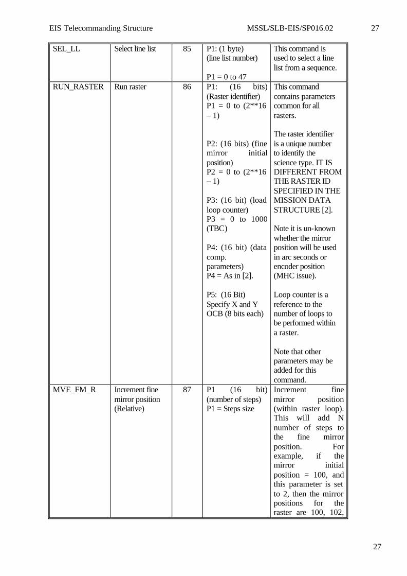
SEL_LL Select line list 85 P1: (1 byte) (line list number) P1 = 0 to 47
This command is used to select a line list from a sequence.
RUN_RASTER Run raster 86 P1: (16 bits) (Raster identifier) P1 = 0 to (2**16 – 1) P2: (16 bits) (fine mirror initial position) P2 = 0 to (2**16 – 1) P3: (16 bit) (load loop counter) P3 = 0 to 1000 (TBC) P4: (16 bit) (data comp. parameters) P4 = As in [2]. P5: (16 Bit) Specify X and Y OCB (8 bits each)
This command contains parameters common for all rasters. The raster identifier is a unique number to identify the science type. IT IS DIFFERENT FROM THE RASTER ID SPECIFIED IN THE MISSION DATA STRUCTURE [2]. Note it is un-known whether the mirror position will be used in arc seconds or encoder position (MHC issue). Loop counter is a reference to the number of loops to be performed within a raster. Note that other parameters may be added for this command.
MVE_FM_R Increment fine mirror position (Relative)
87 P1 (16 bit) (number of steps) P1 = Steps size
Increment fine mirror position (within raster loop). This will add N number of steps to the fine mirror position. For example, if the mirror initial position = 100, and this parameter is set to 2, then the mirror positions for the raster are 100, 102,

EIS Telecommanding Structure MSSL/SLB-EIS/SP016.02 28
28
104, etc depending on the number of loops.
MVE_FM_A Move fine mirror (absolute position).
88 P1 (16 bit) (mirror position as required by the MHC)
Move mirror to an absolute position. To be used for non-uniform rastering (uneven mirror steps)
LOOP_BACK Loop back 89 P1 (8 bits) (location in sequence) P1 = 0 to 255
Loop back to a sequence location. Number of loops loaded as run raster is decremented by 1. The loop is terminated if number of loops = 0.
SEQ_WAIT Delay 8A P1: (16 bit) (delay period) P1 = 1 to (2^16 – 1) (ms)
Delay in unit of ms.
SET_FLUSH_ NO
Set number of flushes
8B P1: (1 Byte) (no. of flushes) P1 = 1 to 255
Flush CCDs N number of times. This should be used prior to raster run in order to get rid of the CCDs access charges. Also it may be useful to perform a single flush prior to shutter opening.
LOAD_MD_P Set mission data parameters.
8C DELETED
This command is not needed.
START_EXP Start exposure 8D P1: (16 bit) (exposure Time) P1 = 1 to (2^16 – 1) In 50 ms units
Set exposure time for this exposure. The exposure time is in unit of 50 ms [1]. For example to set the exposure time to 1 second, then: P1 = 20 i.e. 20*50 = 1000 ms. When AEC is enabled, then this parameter should be
EIS Telecommanding Structure MSSL/SLB-EIS/SP016.02 29
29
set to 0 (TBC).