Эффективность помощи и проблемы дополнительных возможностей бюджета

MTG
PLU
S
MTGPLUS

MTG
PLU
SM
TG P
LUS
MTG
PLU
S
MTGPLUSand complementary products y productos complementarios et produits complémentaires und Ergänzungsprodukte дополнительных продуктов
INDEX
Most popular systems in the market Sistemas más populares del mercado Systèmes plus populaires du marché Gebräuchliche Systeme im Markt Наиболее популярные системы на рынке
MTG Plus adaptable to Caterpillar* Side Pin ............................................................................272
MTG Plus adaptable to Caterpillar* Ripper ..............................................................................276
Remop adaptable to Caterpillar* Motograders .........................................................................279
MTG Plus adaptable to Caterpillar* Vertical Pin .......................................................................280
MTG Plus adaptable to Komatsu* Side Pin ...............................................................................282
MTG Plus adaptable to Komatsu* Ripper ..................................................................................284
MTG Plus shrouds ......................................................................................................................285
Other Systems Otros Sistemas Autres Systèmes Andere Systeme Другие системы
MTG Plus adaptable to Conical* ...............................................................................................291
MTG Plus adaptable to Conical* Ripper ....................................................................................293
MTG Plus adaptable to Dredge Superconical* ..........................................................................295
MTG Plus adaptable to H&L* .....................................................................................................297
Monoblocs ..................................................................................................................................298
MTG Plus adaptable to Orca* .....................................................................................................299
MTG Plus adaptable to Poclain* ................................................................................................300
Assembly and disassembly instructions for MTG twist ............................................................302
LHD Weld on shrouds installation .............................................................................................302
General welding instructions ....................................................................................................308M
TG P
LUS

MTGPLUSand complementary products y productos complementarios et produits complémentaires und Ergänzungsprodukte дополнительных продуктов
272MTG
PLU
S
MTG
20 22 25 30 35 40 46 55 60 70 80
20 22 25 30 35 40 45 46 55 60 70 Pin - - - - 2MC35P 2MC40P 2MC45P1 2MC45P 2MC55P 2MC60P 2MC70PRetainer + Plug - - - - 2MC35R 2MC40R 2MC35R 2MC45R 2MC55R 2MC60R 2MC70RTool - - - - 3MTWIST M 3MTWIST M 3MTWIST X 3MTWIST X 3MTWIST X 3MTWIST X 3MTWIST X Supplement - - - - 2MC35S 2MC40S 2MC35S 2MC45S 2MC55S 2MC60S 2MC70/80S
MTGtwist
20 22 25 30 35 40 45 46 55 60 70 80P R8E6208 R6Y3228 R8E6258 R107-3308 R8E6358 R7T3408 R4T1458-G R8E0468 R6Y8558 R6I6608 R9U9616-G R1020101R R8E6209 R8E6259 R8E6259 R8E6259 R8E6359 R8E8409 R8E6359 R8E8469 R8E5559 R6I6609 R4T4707 R1012874
Remop
Caterpillar* Side Pin
no Hammerless no H.Hammerless
S MC20S MC22S MC25S MC30S MC35S1 - MC45S1 MC55S1 - - - U - - MC25U MC30U MC35U1 MC40U1 MC45U1 MC55U1 - MC70U1 - F - - - MC30F MC35F1 MC40F1 MC45F1 MC55F1 - - - P - - - MC30P MC35P1 MC40P1 MC45P1 MC55P1 MC60P1 - - E - - - MC30E MC35E1 MC40E1 MC45E1 MC55E1 MC60E1 MC70E1 - EX - - - - - - MC45EX1 - - - - V MC20V - MC25V MC30V MC35V1 MC40V1 MC45V1 MC55V1 MC60V1 MC70V1 - W MC20W - - MC30W MC35W1 MC40W1 MC45W1 MC55W1 - - WI - - MC25WI - MC35WI1 - MC45WI1 - MC60WI1 - - I / - - MC25I MC30I MC35I1 - - - - - - IX / - - - - - - MC45IX1 MC55IX1 - - - L MC20L - MC25L MC30L MC35L1 MC40L1 MC45L1 MC55L1 - - - D - - - - - - - - - MC70D1 - H - - - MC30H MC35H1 MC40H1 MC45H1 MC55H1 - - MC80H A - - MC25A MC30A MC35A1 MC40A1 MC45A1 MC55A1 MC60A1 MC70A1 MC80A AX - - - - MC35AX1 - MC45AX1 MC55AX1 MC60AX1 - -
Teeth Dientes Dents Zähne
Locking system Anclajes Système de clavetage Sicherung Система крепления

MTGPLUSand complementary products y productos complementarios et produits complémentaires und Ergänzungsprodukte дополнительных продуктов
273 MTG
PLU
S
MTG
Caterpillar* Side Pin
A B D E Ref. mm inch mm inch mm inch mm inch
20 MC20S 162 6.38 32 1.26 58 2.28 66 2.60 1,2 2.6 MC20V 173 6.81 4 0.16 58 2.28 66 2.60 1,1 2.5 MC20W 173 6.81 83 3.27 58 2.28 66 2.60 1,4 3.1 MC20L 161 6.34 61 2.40 58 2.28 66 2.60 1,3 2.922 MC22S 188 7.40 37 1.46 68 2.68 85 3.35 2,1 4.525 MC25S 210 8.27 39 1.54 77 3.03 91 3.58 2,6 5.7 MC25U 214 8.43 80 3.15 77 3.03 91 3.58 3,4 7.6 MC25V 220 8.66 6 0.24 77 3.03 91 3.58 2,6 5.7 MC25WI 205 8.07 104 4.09 77 3.03 91 3.58 2,9 6.5 / MC25I 175 6.89 48 1.89 77 3.03 91 3.58 2,3 5.2 MC25L 211 8.31 81 3.19 77 3.03 91 3.58 3,5 7.8 MC25A 240 9.45 50 1.97 77 3.03 91 3.58 5,2 11.530 MC30S 237 9.33 46 1.81 93 3.66 110 4.33 4,1 9.1 MC30U 241 9.49 90 3.54 93 3.66 110 4.33 4,8 10,6 MC30F 234 9.21 150 5.91 93 3.66 110 4.33 5,2 11.5 MC30P 230 9.06 35 1.38 93 3.66 110 4.33 4,1 8.9 MC30E 250 9.84 47 1.85 93 3.66 110 4.33 5,5 12.0 MC30V 250 9.84 6 0.24 93 3.66 110 4.33 4,3 9.6 MC30W 250 9.84 138 5.43 93 3.66 110 4.33 5,1 11.1 / MC30I 199 7.83 57 2.24 93 3.66 110 4.33 3,9 8.7 MC30L 237 9.33 90 3.54 93 3.66 110 4.33 5,2 11.4 MC30H 238 9.37 59 2.32 93 3.66 110 4.33 6,3 13.9 MC30A 264 10.39 45 1.77 93 3.66 110 4.33 6,9 15.335 MC35S1 262 10.31 58 2.28 106 4.17 120 4.72 5,7 12.7 MC35U1 250 9.84 100 3.94 106 4.17 120 4.72 6,2 13.6 MC35F1 271 10.67 182 7.17 106 4.17 120 4.72 8,1 17.9 MC35P1 256 10.08 39 1.54 106 4.17 120 4.72 5,4 11.9 MC35E1 278 10.94 61 2.40 106 4.17 120 4.72 7,1 15.7 MC35V1 280 11.02 6 0.24 106 4.17 120 4.72 5,6 12.3 MC35W1 280 11.02 145 5.71 106 4.17 120 4.72 7,0 15.4 MC35WI1 264 10.39 147 5.79 106 4.17 120 4.72 6,2 13.7 / MC35I1 217 8.54 64 2.52 106 4.17 120 4.72 5,3 11.7 MC35L1 265 10.43 106 4.17 106 4.17 120 4.72 6,7 14.9 MC35H1 267 10.51 78 3.07 106 4.17 120 4.72 8,8 19.4 MC35A1 293 11.54 53 2.09 106 4.17 120 4.72 10,4 23.0 MC35AX1 310 12.20 67 2.64 106 4.17 120 4.72 12,9 28.440 MC40U1 297 11.69 119 4.69 120 4.72 137 5.39 10,2 22.5 MC40F1 277 10.91 214 8.43 120 4.72 137 5.39 11,4 25.2 MC40P1 288 11.34 36 1.42 120 4.72 137 5.39 7,9 17.5 MC40E1 305 12.01 64 2.52 120 4.72 137 5.39 11,2 24.8 MC40V1 307 12.09 8 0.31 120 4.72 137 5.39 7,2 16.0 MC40W1 307 12.09 167 6.57 120 4.72 137 5.39 9,2 20.3
Teeth Dientes Dents Zähne
LONG (L)
ABRASION X (AX)
FLARED (F)
ABRASION (A)
UNIVERSAL (U)
HEAVY (H)
STANDARD (S)
DELTA (D)

MTGPLUSand complementary products y productos complementarios et produits complémentaires und Ergänzungsprodukte дополнительных продуктов
274MTG
PLU
S
Teeth Dientes Dents Zähne
MTG
A B D E Ref. mm inch mm inch mm inch mm inch
40 MC40L1 290 11.42 103 4.06 120 4.72 137 5.39 10,7 23.6 MC40H1 299 11.77 139 5.47 120 4.72 137 5.39 13,5 29.8 MC40A1 330 12.99 61 2.40 120 4.72 137 5.39 14,0 30.945 MC45S1 318 12.52 61 2.40 134 5.28 140 5.51 11,4 25.1 MC45U1 325 12.80 125 4.92 134 5.28 140 5.51 13,4 29.7 MC45F1 311 12.24 229 9.02 134 5.28 140 5.51 15,5 34.2 MC45P1 312 12.28 32 1.26 134 5.28 140 5.51 10,2 22.5 MC45E1 338 13.31 54 2.13 134 5.28 140 5.51 14,8 32.6 MC45EX1 335 13.19 136 5.35 134 5.28 140 5.51 16,1 35.4 MC45V1 335 13.19 8 0.31 134 5.28 140 5.51 9,4 20.7 MC45W1 340 13.29 183 7.20 134 5.28 140 5.51 13,0 28.7 MC45IW1 335 13.19 170 6.69 140 5.51 140 5.51 14,3 31.5 / MC45IX1 267 10.51 116 4.57 134 5.28 140 5.51 10,8 23.8 MC45L1 315 12.40 63 2.48 134 5.28 140 5.51 13,5 29.7 MC45H1 329 12.95 77 3.03 134 5.28 140 5.51 16,8 37.2 MC45A1 355 13.98 66 2.60 134 5.28 140 5.51 20,3 44.7 MC45AX1 355 13.98 95 3.74 138 5.43 143 5.63 23,3 51.455 MC55U1 375 14.76 115 6.10 159 6.26 155 6.10 20,9 46.1 MC55S1 355 13.98 76 2.99 159 6.26 155 6.10 16,0 35.2 MC55F1 360 14.17 283 11.14 159 6.26 155 6.10 27,7 61.1 MC55P1 357 14.06 40 1.57 159 6.26 155 6.10 15,1 33.4 MC55E1 375 14.76 78 3.07 159 6.26 155 6.10 20,9 46.1 MC55V1 370 14.57 9 0.35 159 6.26 155 6.10 13,5 29.7 MC55W1 370 14.57 220 8.66 159 6.26 155 6.10 18,6 40.9 / MC55IX1 302 11.89 127 5.00 160 6.30 155 6.14 15,2 33.5 MC55L1 354 13.94 104 4.09 159 6.26 155 6.10 20,6 45.5 MC55H1 360 14.17 118 4.65 159 6.26 155 6.10 27,6 60.8 MC55A1 385 15.16 61 2.40 159 6.26 155 6.10 30,0 66.1 MC55AX1 401 15.80 115 4.55 159 6.26 155 6.10 32,6 71.860 MC60P1 410 16.14 49 1.93 199 7.83 196 7.72 26,6 58.6 MC60E1 435 17.13 103 4.06 199 7.83 196 7.72 38,5 84.9 MC60V1 430 16.93 6 0.24 199 7.83 196 7.72 26,6 58.6 MC60WI1 430 16.93 243 9.57 199 7.83 196 7.72 31,6 69.7 MC60A1 454 17.87 115 4.53 199 7.83 196 7.72 52,5 115.7 MC60AX1 479 18.86 122 4.80 199 7.83 196 7.72 60,5 133.470 MC70U1 441 17.36 203 7.99 212 8.35 229 9.02 46,6 102.7 MC70E1 510 20.08 136 5.35 212 8.35 229 9.02 51,8 114.2 MC70V1 455 17.91 9 0.35 212 8.35 212 8.35 32,0 70.5 MC70D1 509 20.04 83 3.27 212 8.35 229 9.02 50,0 110.2 MC70A1 494 19.45 142 5.59 212 8.35 229 9.02 60,3 132.980 MC80H 495 19.49 245 9.63 240 9.45 240 9.45 86,1 189.8 MC80A 572 22.52 125 4.92 240 9.45 240 9.45 98,0 216.1
Caterpillar* Side Pin
PENETRATION (P)
DOUBLE VECTOR (W)
EXTRA (E)
DOUBLE VECTOR IMPACT (WI)
EXTRA X (EX)
IMPACT (I)
VECTOR (V)
IMPACT X (IX)

MTGPLUSand complementary products y productos complementarios et produits complémentaires und Ergänzungsprodukte дополнительных продуктов
275 MTG
PLU
S
Locking system Anclajes Système de clavetage Sicherung Система крепления
B
Caterpillar* Side Pin
PIN RETAINER + PLUG SUPPLEMENT
TOOL
Ref.B
inchRef.
Talla Binch
3MTWIST M 1/4 - 3/83MTWIST X 1/2 - 5/8
3MTWIST M 35 3/840 3/8
3MTWIST X(old version)
45 1/255 1/260 5/870 5/8
RemopMTGtwist
20 P R8E6208 11 0.43 R R8E6209 22 P R6Y3228 14 0.55 R R8E6259 25 P R8E6258 14 0.55 R R8E6259 30 P R107-3308 14 0.55 R R8E6259 35 P 2MC35P R8E6358 19 0.75 R 2MC35R R8E6359 40 P 2MC40P R7T3408 22 0.87 R 2MC40R R8E8409 45 P 2MC45P1 R4T1458-G 19 0.75 R 2MC35R R8E6359 46 P 2MC45P R8E0468 24 0.94 R 2MC45R R8E8469 55 P 2MC55P R6Y8558 25 0.98 R 2MC55R R8E5559 60 P 2MC60P R6I6608 30 1.18 R 2MC60R R6I6609 70 P 2MC70P R9U9616-G 32 1.26 R 2MC70/80R R4T4707 80 P R1020101 35 1.38 R R1012874
B MTGtwist Remop mm inch

MTGPLUSand complementary products y productos complementarios et produits complémentaires und Ergänzungsprodukte дополнительных продуктов
276MTG
PLU
S
30 35 45 50 55
MTG
Teeth Dientes Dents Zähne Зубья
30 35 45 50 55
Remop
Locking system Anclajes Système de clavetage Sicherung Система крепления
(*) Locking System non reusable, only available in Europe Sistema de anclaje no reutilizable, sólo disponible en Europa Système de clavetage non réutilisable. Seulement valableen Europe Sicherungssystem nicht wiederverwendbar, nur in Europa verfügbar Многоразовые системы крепления, доступны только в Европе
Caterpillar* Ripper
I - - MR45I MR50I MR55I S MR30S MR35S MR45S MR50S MR55S P MR30P MR35P MR45P MR50P MR55P A - MR35A MR45A - - AX - - - MR50AX -
I - - R4T2479 R3G0500 R9W1821 II R9J6583 - - - - III - R8E6358 - - - IV R1U2405 R1U2405 - - - V - - - R6Y1204* - VI - - - R6Y1202* -

MTGPLUSand complementary products y productos complementarios et produits complémentaires und Ergänzungsprodukte дополнительных продуктов
277 MTG
PLU
S
MTG
A B D E Ref. mm inch mm inch mm inch mm inch
Teeth Dientes Dents Zähne Зубья
Caterpillar* Ripper
ABRASION (A) ABRASION X (AX)PENETRATION (P)STANDARD (S)IMPACT (I)
30 D4. 963. 955. 951. 163H. MR30S 292 11.50 48 1.89 88 3.46 119 4.69 5,2 11.6 160H. 143H. 140. 130. 14. 12 MR30P 298 11.73 38 1.50 88 3.46 119 4.69 5,2 11.635 D7. D6. D6N. D5. MR35S 338 13.31 68 2.68 108 4.25 159 6.26 10,5 23.3 D5N. 977. 973. 16 MR35P 348 13.70 52 2.05 108 4.25 159 6.26 10,9 24.0 MR35A 389 15.31 61 2.40 108 4.25 159 6.26 11,5 25.345 D9. D8L. D8 MR45I 343 13.50 68 2.68 122 4.80 183 7.20 14,9 33.0 MR45S 388 15.28 74 2.91 122 4.80 183 7.20 16,3 35.9 MR45P 399 15.71 65 2.56 122 4.80 183 7.20 15,8 34.9 MR45A 423 16.65 65 2.56 122 4.80 183 7.20 18,1 39.950 D11 MS. D10N. D10. D9L MR50I 403 15.87 77 3.03 151 5.94 233 9.17 26,8 59.1 MR50S 443 17.44 76 2.99 151 5.94 233 9.17 29,0 64.0 MR50P 452 17.80 68 2.68 151 5.94 233 9.17 29,1 64.1 MR50A 482 18.98 76 2.99 151 5.94 233 9.17 30,2 66.6 MR50AX 480 18.90 76 2.99 151 5.94 233 9.17 27,7 61.155 D11 (SS. DR) MR55I 481 18.94 85 3.35 184 7.24 285 11.22 44,4 97.9 MR55S 559 22.01 81 3.19 184 7.24 285 11.22 45,1 99.4 MR55P 555 21.85 69 2.72 180 7.09 275 10.83 43,1 94.9

MTGPLUSand complementary products y productos complementarios et produits complémentaires und Ergänzungsprodukte дополнительных продуктов
278MTG
PLU
S
Locking system Anclajes Système de clavetage Sicherung Система крепления
B Ref. mm inch
Remop
(*) Locking System non reusable, only available in Europe Sistema de anclaje no reutilizable, sólo disponible en Europa Système de clavetage non réutilisable. Seulement valableen Europe Sicherungssystem nicht wiederverwendbar, nur in Europa verfügbar Многоразовые системы крепления, доступны только в Европе
Caterpillar* Ripper
I
IV
II
VI
III
VII
30 II R9J6583 19 0.75 IV R1U2405 - -35 III R8E6358 19 0.75 IV R1U2405 - -45 I R4T2479 25 0.9850 I R3G0500 32 1.26 V R6Y1204 * 32 1.26 VI R6Y1202 * - -55 I R9W1821 35 1.38
MTGPLUSand complementary products y productos complementarios et produits complémentaires und Ergänzungsprodukte дополнительных продуктов
279 MTG
PLU
S
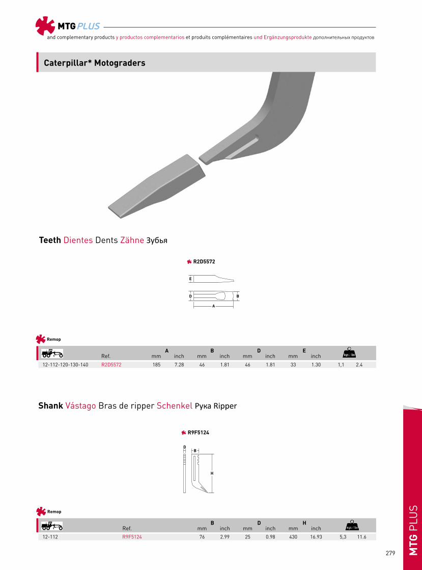
Teeth Dientes Dents Zähne Зубья
Remop
A B D E Ref. mm inch mm inch mm inch mm inch
12-112-120-130-140 R2D5572 185 7.28 46 1.81 46 1.81 33 1.30 1,1 2.4
Remop
B D H Ref. mm inch mm inch mm inch
12-112 R9F5124 76 2.99 25 0.98 430 16.93 5,3 11.6
Shank Vástago Bras de ripper Schenkel Pука Ripper
R2D5572
R9F5124
Caterpillar* Motograders

MTGPLUSand complementary products y productos complementarios et produits complémentaires und Ergänzungsprodukte дополнительных продуктов
280MTG
PLU
S
14 15
MTG
L / MV14L MV15L
Teeth Dientes Dents Zähne Зубья
14 15
Remop
P R4K0043 R4K0043 R R4K0041 R4K0041
Locking system Anclajes Système de clavetage Sicherung Система крепления
Caterpillar* Vertical Pin

MTGPLUSand complementary products y productos complementarios et produits complémentaires und Ergänzungsprodukte дополнительных продуктов
281 MTG
PLU
S
MTG
A B D E Ref. mm inch mm inch mm inch mm inch
14 / MV14L 182 7.17 53 2.09 57 2.24 71 2.80 1,4 3.015 / MV15L 191 7.52 65 2.56 71 2.80 71 2.80 1,8 3.9
14-15 P R4K0043 68 2.68 18 0.71 R R4K0041 44 1.73 23 0.91
A B Ref. mm inch mm inch
Teeth Dientes Dents Zähne Зубья
Locking system Anclajes Système de clavetage Sicherung Система крепления
Remop
Caterpillar* Vertical Pin
LONG (L)
P R

MTGPLUSand complementary products y productos complementarios et produits complémentaires und Ergänzungsprodukte дополнительных продуктов
282MTG
PLU
S
200 300 400 650 1000
MTG
S MK200S MK300S MK400S - - E MK200E MK300E MK400E MK650E MK1000E V MK200V MK300V MK400V MK650V -
Teeth Dientes Dents Zähne Зубья
Locking system Anclajes Système de clavetage Sicherung Система крепления
200 300 400 650 1000
Remop
Ref R09244-02496 R175-78-21810 R09244-03036 R209-70-54240 R21N-72-14330
Komatsu* Side Pin

MTGPLUSand complementary products y productos complementarios et produits complémentaires und Ergänzungsprodukte дополнительных продуктов
283 MTG
PLU
S
Teeth Dientes Dents Zähne Зубья
Locking system Anclajes Système de clavetage Sicherung Система крепления
MTG
A B D E Ref. mm inch mm inch mm inch mm inch
B Ref. mm inch
Remop
Komatsu* Side Pin
STANDARD (S)
PIN
EXTRA (E) VECTOR (V)
200 MK200S 244 9.61 56 2.20 98 3.86 115 4.53 4,6 10.1 MK200E 267 10.51 58 2.28 98 3.86 115 4.53 5,6 12.3 MK200V 270 10.63 6 0.24 98 3.86 115 4.53 4,7 10.4 300 MK300S 268 10.55 74 2.91 124 4.88 126 4.96 6,2 10.7 MK300E 294 11.57 67 2.64 124 4.88 126 4.96 8,6 18.9 MK300V 300 11.81 6.9 0.24 124 4.88 126 4.96 6,5 14.3 400 MK400S 314 12.36 65 2.56 148 5.83 134 5.28 10,3 22.7 MK400E 328 12.91 73 2.87 148 5.83 134 5.28 12,4 27.3 MK400V 340 13.39 9 0.35 148 5.83 134 5.28 9,4 20.7 650 MK650E 431 16.97 98 3.86 183 7.20 201 7.91 29,5 65.0 MK650V 430 16.93 12 0.47 183 7.20 201 7.91 22,1 48.71000 MK1000E 500 19.69 103 4.06 185 7.28 263 10.35 43,6 96.1
200 R09244-02496 26 1.02 300 R175-78-21810 26 1.02 400 R09244-03036 32 1.26 650 R209-70-54240 38 1.501000 R21N-72-14330 40 1.57

MTGPLUSand complementary products y productos complementarios et produits complémentaires und Ergänzungsprodukte дополнительных продуктов
284MTG
PLU
S
Teeth Dientes Dents Zähne Зубья
Locking system Anclajes Système de clavetage Sicherung Система крепления
D85-21, D355, 15S R175.78.21740 25 0.98D375A-2 R195.78.71360 30 1.18D60, 65-8, D75 5-5 R4T2479 25 0.98
B Ref. mm inch
Remop
MTG
A B D E Ref. Ref. Orig. mm inch mm inch mm inch mm inch
Komatsu* Ripper
PIN
MKR155IR MKR355AR MKR375A2A
D85-21, 15S MKR155IR 175.78.31230 336 13.23 75 2.95 120 4.72 160 6.30 15,0 33.1D355 MKR355AR R355-A 386 15.20 76 2.99 120 4.72 189 7.44 19,1 42.2D375A-2 MKR375A2A 195.78.71320 435 17.13 90 3.54 120 4.72 215 8.46 26,6 58.6

MTGPLUSand complementary products y productos complementarios et produits complémentaires und Ergänzungsprodukte дополнительных продуктов
285 MTG
PLU
S
BC - - - 4ML45BC 4ML50BC312 - - - - - - - BLD - - - 4ML45BLD 4ML50BLD312 - - - - - - -BRD - - - 4ML45BRD 4ML50BRD312 - - - - - - - BC-A - - - - 4ML50BC-A - - - - - - - BCX - - - - - - - 4ML100BCX440 - - - - - - - - - - - 4ML100BCX622 - - - - BCX-A - - - - - 4ML70BCX-A - - - - - - BLD-A - - - - 4ML50BLD-A - - - - - - -BLDX - - - - - - - 4ML100BLDX - - - -BLDX-A - - - - - 4ML70BLDX-A - - - - - -BRD-A - - - - 4ML50BRD-A - - - - - - -BRDX - - - - - - - 4ML100BRDX - - - - BRDX-A - - - - - 4ML70BRDX-A - - - - - - UC - - - - 4ML50UC 4ML70UC 4ML90UC - 4ML120UC - - -UC2 - - - - - 4ML70UC2 4ML90UC2 - - - - -UC3 / - - - - 4ML50UC3 4ML70UC3 4ML90UC3 - - - - -UC5 / - - - - 4ML50UC5 - - - - - - -ULD - - - - - 4ML70ULD 4ML90ULD - 4ML120ULD - - -URD - - - - - 4ML70URD 4ML90URD - 4ML120URD - - -
UL 4MB20UL 4MB25UL 4MB30UL - - 4MB70UL - - - - - - ULH - - 4MB30ULH - - - - - 4MB130ULH 4MB300ULH 4MB300ULHULHX - - 4MB30ULHX - - - - - - - - -
LX - - - 4MB4542-LX - - - - - - - RX - - - 4MB4542-RX - - - - - - -
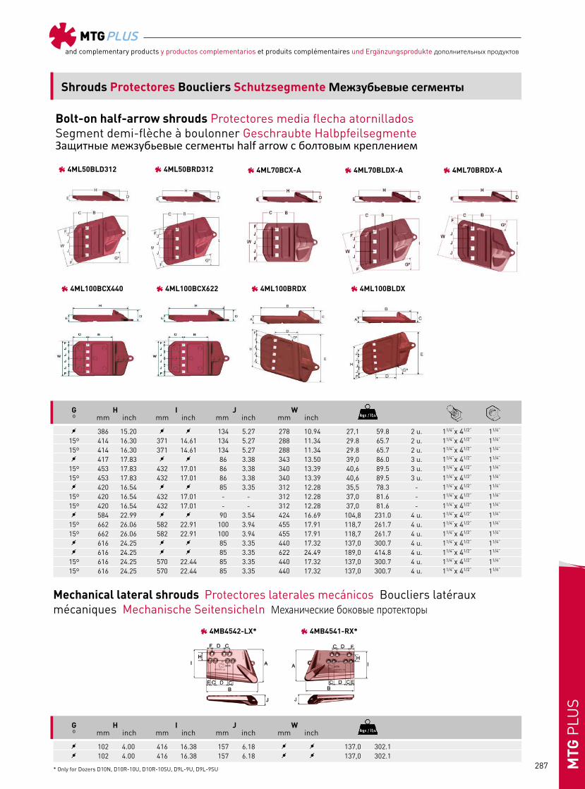
Shrouds Protectores Boucliers Schutzsegmente Межзубьевые сегменты
Shrouds Protectores Boucliers Schutzsegmente
Weld-on corner Cantoneras soldables Boucliers d’angle à souder Corner Seitensicheln geschweisst Приварные угловые детали
Weld-on lateral Laterales soldables Couteaux latéraux à souder Seitensicheln geschweisst Боковые протекторы
Bolt-on half-arrow Atornillados media flecha Segment demi-flèche à boulonner Geschraubte Halbpfeilsegmente Защитные межзубьевые сегменты half arrow с болтовым креплением
Weld-on Soldables Boucliers à souder Segment geschweisst Приварные межзубьевые сегменты
20 25 30 45 50 70 90 100 120 130 300 500
Bolt-on half-arrow • Atornillados media flecha • Segment demi-flèche à boulonner • Geschraubte HalbpfeilsegmenteЗащитные межзубьевые сегменты half arrow с болтовым креплением
Weld-on • Soldables • Boucliers à souder • Segment geschweisst • Приварные межзубьевые сегменты
Weld-on lateral • Laterales soldables • Couteaux latéraux à souder • Seitensicheln geschweisst • Боковые протекторы
Weld-on corner • Cantoneras soldables • Boucliers d’angle à souder • Corner Seitensicheln geschweisst • Приварные угловые детали
Mechanical laterals shrouds • Protectores laterales mecánicos • Boucliers latéraux mécaniques • Mechanische Seitensicheln • Механические боковые протекторы

MTGPLUSand complementary products y productos complementarios et produits complémentaires und Ergänzungsprodukte дополнительных продуктов
286MTG
PLU
S
4ML45BLD
Bolt-on half-arrow shrouds Protectores media flecha atornillados Segment demi-flèche à boulonner Geschraubte Halbpfeilsegmente Защитные межзубьевые сегменты half arrow с болтовым креплением
B C D E F Ref. mm inch mm inch mm inch mm inch mm inch mm inch
A B C D E F Ref. mm inch mm inch mm inch mm inch mm inch mm inch
Shrouds Protectores Boucliers Schutzsegmente Межзубьевые сегменты
4ML45BC
4ML50BC-A 4ML50BC312
4MB4541-RX* 4MB4542-LX
4ML45BC BC 45 1.75 126 4.96 135 5.31 72 2.83 47 1.85 72 2.834ML45BLD BLD 45 1.75 126 4.96 135 5.31 72 2.83 47 1.85 79 3.114ML45BRD BRD 45 1.75 126 4.96 135 5.31 72 2.83 47 1.85 79 3.114ML50BC-A BC-A 51 2.01 136 5.36 141 5.55 74 2.91 49 1.93 85 3.354ML50BLD-A BLD-A 51 2.01 136 5.36 141 5.55 74 2.91 49 1.93 87 3.434ML50BRD-A BRD-A 51 2.01 136 5.35 141 5.55 74 2.91 49 1.93 87 3.434ML50BC312 BC312 - - 140 5.51 137 5.39 74 2.91 49 1.93 71 2.804ML50BLD312 BLD312 - - 140 5.51 - - 75 2.95 49 1.93 74 2.914ML50BRD312 BRD312 - - 140 5.51 - - 74 2.91 49 1.93 74 2.914ML70BCX-A BCX-A - - 180 7.09 150 5.91 125 4.92 75 2.95 77 3.034ML70BLDX-A BLDX-A - - 180 7.09 175 6.89 125 4.92 75 2.95 83 3.274ML70BRDX-A BRDX-A - - 180 7.09 175 6.89 125 4.92 75 2.95 83 3.274ML100BCX440 BCX 100 3.94 270 10.63 167 6.57 150 5.91 85 3.35 50 1.974ML100BCX622 BCX 100 3.94 270 10.63 167 6.57 150 5.91 85 3.35 50 1.974ML100BRDX BRDX 100 3.94 270 10.63 167 6.57 150 5.91 85 3.35 56 1.974ML100BLDX BLDX 100 3.94 270 10.63 167 6.57 150 5.91 85 3.35 56 1.97
4MB4542-LX* LX 479 18.86 741 29.17 76 3.00 178 7.00 51 2.01 76 2.994MB4541-RX* RX 479 18.86 741 29.17 76 3.00 178 7.00 51 2.01 76 2.99
4ML45BCX 4ML45BLDX
4ML45BRDX 4ML50BRD-A4ML50BLD-A
4ML45BRD
Mechanical lateral shrouds Protectores laterales mecánicos Boucliers latéraux mécaniques Mechanische Seitensicheln Механические боковые протекторы
* Only for Dozers D10N, D10R-10U, D10R-10SU, D9L-9U, D9L-9SU.
MTGPLUSand complementary products y productos complementarios et produits complémentaires und Ergänzungsprodukte дополнительных продуктов
287 MTG
PLU
S
/ 386 15.20 / / 134 5.27 278 10.94 27,1 59.8 2 u. 11/4”x 41/2” 11/4”
15º 414 16.30 371 14.61 134 5.27 288 11.34 29.8 65.7 2 u. 11/4”x 41/2” 11/4”
15º 414 16.30 371 14.61 134 5.27 288 11.34 29.8 65.7 2 u. 11/4”x 41/2” 11/4”
/ 417 17.83 / / 86 3.38 343 13.50 39,0 86.0 3 u. 11/4”x 41/2” 11/4”
15º 453 17.83 432 17.01 86 3.38 340 13.39 40,6 89.5 3 u. 11/4”x 41/2” 11/4”
15º 453 17.83 432 17.01 86 3.38 340 13.39 40,6 89.5 3 u. 11/4”x 41/2” 11/4”
/ 420 16.54 / / 85 3.35 312 12.28 35,5 78.3 - 11/4”x 41/2” 11/4”
15º 420 16.54 432 17.01 - - 312 12.28 37,0 81.6 - 11/4”x 41/2” 11/4”
15º 420 16.54 432 17.01 - - 312 12.28 37,0 81.6 - 11/4”x 41/2” 11/4”
/ 584 22.99 / / 90 3.54 424 16.69 104,8 231.0 4 u. 11/4”x 41/2” 11/4”
15º 662 26.06 582 22.91 100 3.94 455 17.91 118,7 261.7 4 u. 11/4”x 41/2” 11/4”
15º 662 26.06 582 22.91 100 3.94 455 17.91 118,7 261.7 4 u. 11/4”x 41/2” 11/4”
/ 616 24.25 / / 85 3.35 440 17.32 137,0 300.7 4 u. 11/4”x 41/2” 11/4”
/ 616 24.25 / / 85 3.35 622 24.49 189,0 414.8 4 u. 11/4”x 41/2” 11/4”
15º 616 24.25 570 22.44 85 3.35 440 17.32 137,0 300.7 4 u. 11/4”x 41/2” 11/4”
15º 616 24.25 570 22.44 85 3.35 440 17.32 137,0 300.7 4 u. 11/4”x 41/2” 11/4”
/ 102 4.00 416 16.38 157 6.18 / / 137,0 302.1 / 102 4.00 416 16.38 157 6.18 / / 137,0 302.1
G H I J W º mm inch mm inch mm inch mm inch
G H I J W º mm inch mm inch mm inch mm inch
Shrouds Protectores Boucliers Schutzsegmente Межзубьевые сегменты
4ML50BLD312
4ML100BCX440
4MB4541-RX* 4MB4542-LX*
4ML100BCX622
4ML50BRD312
4ML100BLDX
4ML100BRDX
4ML70BCX-A 4ML70BLDX-A 4ML70BRDX-A
Bolt-on half-arrow shrouds Protectores media flecha atornillados Segment demi-flèche à boulonner Geschraubte Halbpfeilsegmente Защитные межзубьевые сегменты half arrow с болтовым креплением
Mechanical lateral shrouds Protectores laterales mecánicos Boucliers latéraux mécaniques Mechanische Seitensicheln Механические боковые протекторы
* Only for Dozers D10N, D10R-10U, D10R-10SU, D9L-9U, D9L-9SU

MTGPLUSand complementary products y productos complementarios et produits complémentaires und Ergänzungsprodukte дополнительных продуктов
288MTG
PLU
Sand complementary products y productos complementarios et produits complémentaires und Ergänzungsprodukte
B D E H W Ref. mm inch mm inch mm inch º mm inch mm inch
MTG
Weld-on shrouds Protectores soldables Boucliers à souder Segment geschweisst
/ 4ML50UC 40 -50 - 36 1.42 79 3.11 30º 207 8.15 150 5.91 7,00 15.43/ 4ML50UC3 40-50 - 36 1.42 79 3.11 30º 207 8.15 300 11.81 13,90 30.64/ 4ML50UC5 - - 36 1.42 79 3.11 30º 207 8.15 1000 39.37 54,24 119.58/ 4ML70UC 60-75 - 61 2.40 117 4.61 30º 238 9.37 250 9.84 21,10 46.52
4ML70UC2 60-75 - 61 2.40 116 4.57 30º 242 9.53 255 10.04 21,60 47.62/ 4ML70UC3 60-75 - 61 2.40 106 4.17 30º 236 9.29 1000 39.37 90,00 198.42/ 4ML70ULD 60-75 - 61 2.40 117 4.61 30º 230 9.06 230 9.06 19,50 42.99/ 4ML70URD 60-75 - 61 2.40 117 4.61 30º 230 9.06 230 9.06 19,50 42.99/ 4ML90UC 80-100 - 88 3.46 138 5.43 30º 230 9.06 356 14.03 31,60 69.67
4ML90UC2 80-100 - 88 3.46 170 6.69 30º 361 14.21 381 15.00 62,50 137.79/ 4ML90UC3 80-100 - 88 3.46 148 5.83 30º 238 9.37 558 21.97 54,70 120.59/ 4ML90ULD 80-100 - 88 3.46 132 5.20 30º 234 9.21 360 14.17 31,90 70.33/ 4ML90URD 80-100 - 88 3.46 132 5.20 30º 234 9.21 360 14.17 31,90 70.33/ 4ML120UC 100-120 - 103 4.06 175 6.89 30º 281 11.06 320 12.60 36,10 79.59/ 4ML120ULD 100-120 - 103 4.06 173 6.81 30º 242 9.53 320 12.60 36,6 80.69/ 4ML120URD 100-120 - 103 4.06 173 6.81 30º 242 9.53 320 12.60 36,6 80.68
ShroudsProtectoresBoucliersSchutzsegmente
4ML70UC24ML70UC4ML50UC54ML50UC34ML50UC
4ML90UC24ML90UC4ML70URD4ML70ULD4ML70UC3
4ML120ULD 4ML120URD4ML120UC4ML90URD4ML90ULD4ML90UC3
MTG
B D E G H W Ref. mm inch mm inch mm inch º º mm inch mm inch
Weld-on shrouds Protectores soldables Boucliers à souder Segment geschweisst Приварные межзубьевые сегменты
/
/
/
/
/
/
/
/
Shrouds Protectores Boucliers Schutzsegmente Межзубьевые сегменты
4ML50UC
4ML70UC3
4ML90UC3
4ML50UC3
4ML70ULD
4ML90ULD
4ML50UC5
4ML70URD
4ML90URD
4ML70UC
4ML970UC
4ML120UC
4ML70UC2
4ML90UC2
4ML120ULD 4ML120URD
/ 4ML50UC 40-50 1.50-2.00 36 1.42 79 3.11 30º / 207 8.15 150 5.91 7,0 15.4/ 4ML50UC3 40-50 1.50-2.00 36 1.42 79 3.11 30º 207 8.15 300 11.81 13,9 30.6/ 4ML50UC5 - - 36 1.42 79 3.11 30º 207 8.15 1000 39.37 55,0 121.3/ 4ML70UC 60-75 2.36-3.00 61 2.40 117 4.61 30º 238 9.37 250 9.84 21,1 46.5
4ML70UC2 60-75 2.36-3.00 61 2.40 116 4.57 30º 242 9.53 255 10.04 21,6 47.6/ 4ML70UC3 60-75 2.36-3.00 61 2.40 106 4.17 30º / 236 9.29 1000 39.37 90,0 198.4/ 4ML70ULD 60-75 2.36-3.00 61 2.40 117 4.61 15º 30º 230 9.06 230 9.06 19,5 42.9/ 4ML70URD 60-75 2.36-3.00 61 2.40 117 4.61 15º 30º 230 9.06 230 9.06 19,5 42.9/ 4ML90UC 80-100 3.15-4.00 88 3.46 138 5.43 30º 230 9.06 356 14.03 31,6 69.6
4ML90UC2 80-100 3.15-4.00 88 3.46 170 6.69 30º 361 14.21 381 15.00 62,5 137.8/ 4ML90UC3 80-100 3.15-4.00 88 3.46 148 5.83 30º 238 9.37 558 21.97 54,7 120.6/ 4ML90ULD 80-100 3.15-4.00 88 3.46 132 5.20 15º 30º 234 9.21 360 14.17 31,9 70.3/ 4ML90URD 80-100 3.15-4.00 88 3.46 132 5.20 15º 30º 234 9.21 360 14.17 31,9 70.3/ 4ML120UC 100-120 4.00-4.75 103 4.06 175 6.89 30º 281 11.06 320 12.60 36,1 79.6/ 4ML120ULD 100-120 4.00-4.75 103 4.06 173 6.81 15º 30º 242 9.53 320 12.60 36,6 80.7/ 4ML120URD 100-120 4.00-4.75 103 4.06 173 6.81 15º 30º 242 9.53 320 12.60 36,6 80.7

MTGPLUSand complementary products y productos complementarios et produits complémentaires und Ergänzungsprodukte дополнительных продуктов
289 MTG
PLU
S
and complementary products y productos complementarios et produits complémentaires und Ergänzungsprodukte
Weld-on lateral shrouds Protectores Laterales soldables Couteaux Latéraux à souder Seitensicheln geschweisst Боковые протекторы
Weld-on lateral shrouds Protectores Laterales soldables Couteaux Latéraux à souder Seitensicheln geschweisst
Боковые протекторы Приварные угловые детали
Shrouds Protectores Boucliers Schutzsegmente Межзубьевые сегмент
B D H W mm inch mm inch mm inch mm inch
MTG
20 / 4MB20UL 68 2.68 20 0.79 457 17.99 3,6 8.125 / 4MB25UL 79 3.11 25 0.98 510 20.08 4,8 10.730 / 4MB30UL 90 3.54 30 1.18 605 23.82 8,5 18.770 / 4MB70UL 14 0.55 39 1.54 110 4.33 265 10.43 3,6 7.9
4MB20UL- 4MB25UL- 4MB30UL 4MB70UL
Weld-on corner shrouds Cantoneras soldables Boucliers d’angle à souder Corner Seitensicheln geschweisst Приварные угловые детали
Weld-on corner shrouds Cantoneras soldables Boucliers d’angle à souder Corner Seitensicheln geschweisst
B C D E H W hcni mm hcni mm hcni mm hcni mm hcni mm hcni mm
MTG
30 / 50 1.97 137 5.39 116 4.57 51 2.01 187 7.36 188 7.40 10,7 23.6
130 / 68 2.68 180 7.09 151 5.94 58 2.28 249 9.80 188 7.40 20,7 44.1300 87 3.43 163 6.42 199 7.83 66 2.60 250 9.84 250 9.84 40 88.2
4MB30ULH 4MB30ULHX4MB300ULH4MB130ULH
/
Tn
Ref.
20-40
40-180180-400
4MB30ULH
Ref.
4MB130ULH4MB300ULH
30 50 1.97 139 5.47 115 4.53 45 1.77 189 7.44 188 7.40 14,6 32.2/ 20-40 4MB30ULHX
/
/
/
/
/
/
/
/
/
/
/
/
Weld-on corner shrouds Cantoneras soldables Boucliers d’angle à souderCorner Seitensicheln geschweisst Приварные угловые детали
Weld-on lateral shrouds Protectores Laterales soldables Couteaux Latéraux à souder Seitensicheln geschweisst
Боковые протекторы
Weld-on corner shrouds Cantoneras soldablesBoucliers d’angle à souder Corner Seitensicheln geschweisst
Приварные угловые детали
Shrouds Protectores Boucliers Schutzsegmente Межзубьевые сегменты
MTG
B D H W Ref. mm inch mm inch mm inch mm inch
B C D E H W Tn Ref. mm inch mm inch mm inch mm inch mm inch mm inch
20 / 4MB20UL 68 2.68 20 0,79 457 17.99 / / 3,6 8.1 25 / 4MB25UL 79 3.11 25 0.98 510 20.08 / / 4,8 10.7 30 / 4MB30UL 90 3.54 30 1.18 605 23.82 / / 8,5 18.7 70 / 4MB70UL 14 0.55 39 1.54 110 4.33 265 10.43 3,6 7.9 70 4MB70ULX 17 0.67 56 2.20 123 4.84 300 11.81 7,7 16.9
30 / 20-40 4MB30ULH 50 1.97 137 5.39 116 4.57 51 2.01 187 7.36 188 7.40 10,7 23.6 30 / 20-40 4MB30ULHX 50 1.97 139 5.47 115 4.53 45 1.77 189 7.44 188 7.40 14,6 32.2 130 / 40-180 4MB130ULH 68 2.68 180 7.09 151 5.94 58 2.28 249 9.80 188 7.40 20,7 44.1 300 / 180-400 4MB300ULH 87 3.43 163 6.42 199 7.83 66 2.60 250 9.84 250 9.84 40 88.2 500 180-400 4MB500ULH 125 4.92 225 8.86 254 10.00 95 3.74 350 13.78 250 9.84 82,5 181.92
4MB20UL-4MB25UL-4MB30UL 4MB70UL 4MB70ULX
4MB30ULH 4MB130ULH 4MB300ULH 4MB30ULHX
and complementary products y productos complementarios et produits complémentaires und Ergänzungsprodukte
Weld-on lateral shrouds Protectores Laterales soldables Couteaux Latéraux à souder Seitensicheln geschweisst Боковые протекторы
Weld-on lateral shrouds Protectores Laterales soldables Couteaux Latéraux à souder Seitensicheln geschweisst
Боковые протекторы Приварные угловые детали
Shrouds Protectores Boucliers Schutzsegmente Межзубьевые сегмент
B D H W mm inch mm inch mm inch mm inch
MTG
20 / 4MB20UL 68 2.68 20 0.79 457 17.99 3,6 8.125 / 4MB25UL 79 3.11 25 0.98 510 20.08 4,8 10.730 / 4MB30UL 90 3.54 30 1.18 605 23.82 8,5 18.770 / 4MB70UL 14 0.55 39 1.54 110 4.33 265 10.43 3,6 7.9
4MB20UL- 4MB25UL- 4MB30UL 4MB70UL
Weld-on corner shrouds Cantoneras soldables Boucliers d’angle à souder Corner Seitensicheln geschweisst Приварные угловые детали
Weld-on corner shrouds Cantoneras soldables Boucliers d’angle à souder Corner Seitensicheln geschweisst
B C D E H W hcni mm hcni mm hcni mm hcni mm hcni mm hcni mm
MTG
30 / 50 1.97 137 5.39 116 4.57 51 2.01 187 7.36 188 7.40 10,7 23.6
130 / 68 2.68 180 7.09 151 5.94 58 2.28 249 9.80 188 7.40 20,7 44.1300 87 3.43 163 6.42 199 7.83 66 2.60 250 9.84 250 9.84 40 88.2
4MB30ULH 4MB30ULHX4MB300ULH4MB130ULH
/
Tn
Ref.
20-40
40-180180-400
4MB30ULH
Ref.
4MB130ULH4MB300ULH
30 50 1.97 139 5.47 115 4.53 45 1.77 189 7.44 188 7.40 14,6 32.2/ 20-40 4MB30ULHX
MTG
Weld-on lateral shrouds Protectores Laterales soldables Couteaux Latéraux à souderSeitensicheln geschweisst Боковые протекторы

MTGPLUSand complementary products y productos complementarios et produits complémentaires und Ergänzungsprodukte дополнительных продуктов
290MTG
PLU
S
Shrouds Protectores Boucliers Schutzsegmente Межзубьевые сегменты
Underground weldable shrouds Protectores underground Boucliers à souder pour la mine souterraine Schaufelschutz für Untertagebergwerke защита ковша для подземных горных погрузчиков
4MLHD38C1050-7 4MLHD38R696-7 4MLHD38L696-7 4MLHD38LC189-7 4MLHD38RC189-7
A B C D F G
Ref. mm inch mm inch mm inch mm inch mm inch º º 4MLHD38C1050-7A 38 1.50 1050 41.34 328 12.91 / / 40 1.57 / 7.5º 186,0 410.14MLHD38L696-7A 38 1.50 696 27.40 93 3.66 314 12.36 40 1.57 / 7.5º 93,7 206.64MLHD38R696-7A 38 1.50 696 27.40 94 3.70 314 12.36 38 1.50 / 7.5º 93,0 205.04MLHD38LC189-7A 38 1.50 189 7.44 365 14.37 523 20.59 38 1.50 / 7.5º 72,0 158.74MLHD38RC189-7A 38 1.50 189 7.44 365 14.37 523 20.59 38 1.50 7.5º / 72,0 158.7

MTGPLUSand complementary products y productos complementarios et produits complémentaires und Ergänzungsprodukte дополнительных продуктов
291 MTG
PLU
S
18 25 30 35 40
MTG
S - MN25S MN30S MN35S MN40S L MN18L MN25L - - -
Teeth Dientes Dents Zähne Зубья
Locking system Anclajes Système de clavetage Sicherung Система крепления
18 25 30 35 40
Remop
Conical*
PN R18-20MPN R25-30PN R25-30PN R35PN R40PN LK R18-20MLK R25-30LK R25-30LK R35-40LK R35-40LK PNR - R25-30PNR R25-30PNR R35PNR R40PNR LKR - R25-30LKR R25-30LKR R35-40LKR R35-40LKR

MTGPLUSand complementary products y productos complementarios et produits complémentaires und Ergänzungsprodukte дополнительных продуктов
292MTG
PLU
S
Teeth Dientes Dents Zähne Зубья
Locking system Anclajes Système de clavetage Sicherung Система крепления
MTG
A B D E Ref. mm inch mm inch mm inch mm inch
B Ref. mm inch
Remop
Conical*
STANDARD (S) LONG (L)
18 / MN18L 145 5.71 54 2.13 60 2.36 54 2.13 1,0 2.225 / MN25S 190 7.48 49 1.93 81 3.19 78 3.07 2,1 4.5 / MN25L 182 7.17 66 2.60 81 3.19 78 3.07 2,2 4.830 / MN30S 191 7.52 60 2.36 96 3.78 82 3.23 2,5 5.535 / MN35S 223 8.78 66 2.60 115 4.53 90 3.54 3,4 7.440 / MN40S 261 10.28 74 2.91 127 5.00 105 4.13 5,5 12.0
PN LK PNR LKR
18 R18-20MPN 13 0.51 R18-20MLK - -25-30 R25-30PN 20 0.79 R25-30LK 20 0.79 R25-30PNR - - R25-30LKR - -35 R35PN 22 0.8735-40 R35-40LK 22 0.8735 R35PNR - - -35-40 R35-40LKR - -40 R40PN 30 1.18 R40PNR - -
MTGPLUSand complementary products y productos complementarios et produits complémentaires und Ergänzungsprodukte дополнительных продуктов
293 MTG
PLU
S
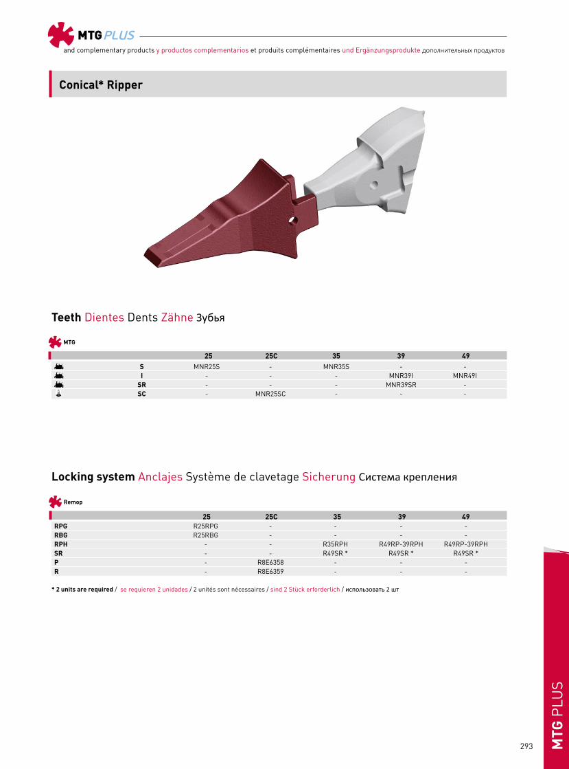
Teeth Dientes Dents Zähne Зубья
Locking system Anclajes Système de clavetage Sicherung Система крепления
25 25C 35 39 49
MTG
25 25C 35 39 49
Remop
* 2 units are required / se requieren 2 unidades / 2 unités sont nécessaires / sind 2 Stück erforderlich / использовать 2 шт
Conical* Ripper
S MNR25S - MNR35S - - I - - - MNR39I MNR49I SR - - - MNR39SR -
SC - MNR25SC - - -
RPG R25RPG - - - -RBG R25RBG - - - -RPH - - R35RPH R49RP-39RPH R49RP-39RPHSR - - R49SR * R49SR * R49SR *P - R8E6358 - - -R - R8E6359 - - -

MTGPLUSand complementary products y productos complementarios et produits complémentaires und Ergänzungsprodukte дополнительных продуктов
294MTG
PLU
S
MTG
A B D E Ref. mm inch mm inch mm inch mm inch
Teeth Dientes Dents Zähne Зубья
25 MNR25S 305 12.01 55 2.17 90 3.54 104 4.09 6,0 13.325C MNR25SC 313 12.32 55 2.17 90 3.54 104 4.09 6,0 13.335 MNR35S 353 13.90 72 2.83 115 4.53 171 6.73 12,0 26.539 MNR39I 398 15.67 77 3.03 158 6.22 191 7.52 18,5 40.8 MNR39SR 429 16.89 77 3.03 148 5.83 216 8.50 22,0 48.549 MNR49I 457 17.99 89 3.50 186 7.32 236 9.29 28,4 62.6
B Ref. mm inch
Locking system Anclajes Système de clavetage Sicherung Система крепления
Remop
Conical* Ripper
MNR25S
MNR39I
RPG RBG RPH SR P R
MNR25SC
MNR39SR
MNR35S
MNR49I
25 RPG R25RPG 13 0.51 RBG R25RBG - -25C P R8E6358 19 0.75 R R8E6359 - -35 RPH R35RPH 22 0.8739-49 RPH R49RP-39RPH 22 0.8735-39-49 SR R49SR - -

MTGPLUSand complementary products y productos complementarios et produits complémentaires und Ergänzungsprodukte дополнительных продуктов
295 MTG
PLU
S
Teeth Dientes Dents Zähne Зубья
Locking system Anclajes Système de clavetage Sicherung Система крепления
44D 54D
MTG
44 54
Remop
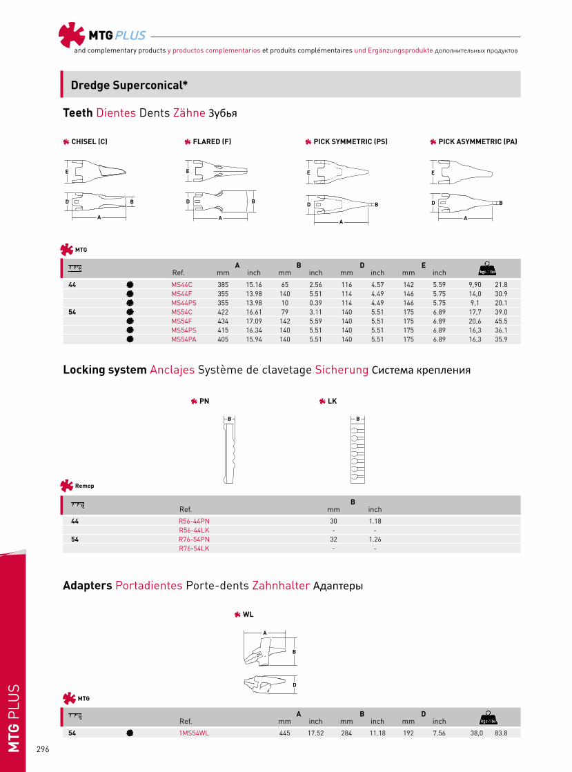
PN R56-44PN R76-54PN LK R56-44LK R76-54LK
54
MTG
WL 1MS54WL
Adapters Portadientes Porte-dents Zahnhalter Адаптеры
Dredge Superconical*
Chisel MS44C MS54C Flared MS44F MS54F Pick Symmetric MS44PS MS54PS Pick Asymmetric - MS54PA
MTGPLUSand complementary products y productos complementarios et produits complémentaires und Ergänzungsprodukte дополнительных продуктов
296MTG
PLU
S
B Ref. mm inch
Teeth Dientes Dents Zähne Зубья
Locking system Anclajes Système de clavetage Sicherung Система крепления
Remop
MTG
A B D Ref. mm inch mm inch mm inch
Adapters Portadientes Porte-dents Zahnhalter Адаптеры
54 1MS54WL 445 17.52 284 11.18 192 7.56 38,0 83.8
MTG
A B D E Ref. mm inch mm inch mm inch mm inch
44 MS44C 385 15.16 65 2.56 116 4.57 142 5.59 9,90 21.8 MS44F 355 13.98 140 5.51 114 4.49 146 5.75 14,0 30.9 MS44PS 355 13.98 10 0.39 114 4.49 146 5.75 9,1 20.154 MS54C 422 16.61 79 3.11 140 5.51 175 6.89 17,7 39.0 MS54F 434 17.09 142 5.59 140 5.51 175 6.89 20,6 45.5 MS54PS 415 16.34 140 5.51 140 5.51 175 6.89 16,3 36.1 MS54PA 405 15.94 140 5.51 140 5.51 175 6.89 16,3 35.9
Dredge Superconical*
CHISEL (C)
PN
WL
LK
FLARED (F) PICK SYMMETRIC (PS) PICK ASYMMETRIC (PA)
44 R56-44PN 30 1.18 R56-44LK - -54 R76-54PN 32 1.26 R76-54LK - -

MTGPLUSand complementary products y productos complementarios et produits complémentaires und Ergänzungsprodukte дополнительных продуктов
297 MTG
PLU
S
Teeth Dientes Dents Zähne Зубья
Locking system Anclajes Système de clavetage Sicherung Система крепления
23 R23 19 0.75
B Ref. mm inch
Remop
MTG
A B D E Ref. mm inch mm inch mm inch mm inch
23 MH23F 133 5.24 110 4.33 61 2.40 68 2.68 1,4 3.2 MH23V 178 7.01 5 0.20 61 2.40 68 2.68 1,1 2.3 MH23W 178 7.01 78 3.07 61 2.40 68 2.68 1,3 2.8 MH23L 158 6.22 54 2.13 61 2.40 68 2.68 1,1 2.5
FLARED (F)
R23
LONG (L) VECTOR (V) DOUBLE VECTOR (W)
H&L*

MTGPLUSand complementary products y productos complementarios et produits complémentaires und Ergänzungsprodukte дополнительных продуктов
298MTG
PLU
S
Remop
A B C D H Ref. mm inch mm inch mm inch mm inch mm inch
Teeth Dientes Dents Zähne Зубья
CAT* 416, 426 R9W1879 20 0.79 50 1.97 75 2.95 51 2.01 280 11.02 2,73 6.02 5/8” x 21/2” 5/8”JCB* R53103205-R 21 0.83 57 2.24 44,5 1.75 50 1.97 245 9.65 1,87 4.12 3/4” x 2 1/2” 3/4” R529 69501P 21 0.83 50 1.97 44,5 1.75 60 2.36 390 15.35 4,87 10.74 3/4” x 21/2” 3/4” R529 69502P 21 0.83 50 1.97 44,5 1.75 60 2.36 390 15.35 4,87 10.74 3/4” x 21/2” 3/4”Massey Ferguson* R146.2201M1 26 1.02 64 2.52 53 2.09 58 2.28 240 9.45 2,60 5.73 5/8” x 21/2” 5/8”
R9W1879 R53103205-RR52969501P R52969502P R146.2201M1
Monoblocs
MTGPLUSand complementary products y productos complementarios et produits complémentaires und Ergänzungsprodukte дополнительных продуктов
299 MTG
PLU
S
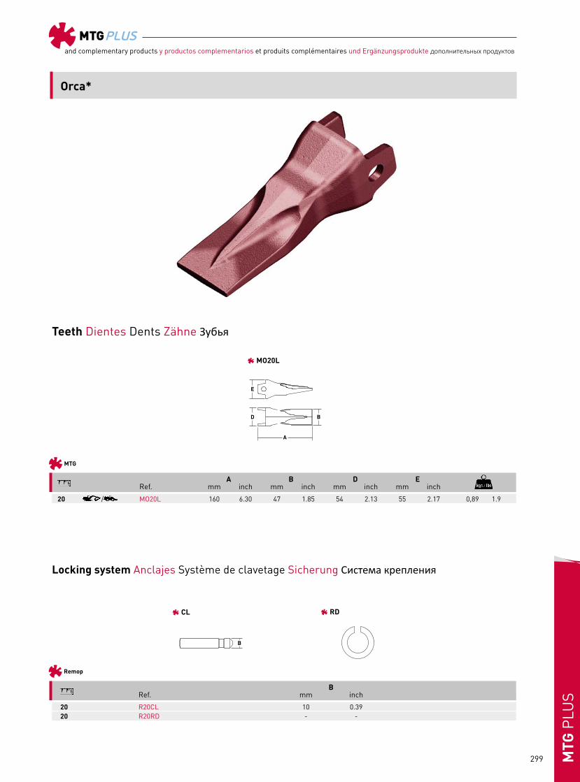
Teeth Dientes Dents Zähne Зубья
Locking system Anclajes Système de clavetage Sicherung Система крепления
A B D E Ref. mm inch mm inch mm inch mm inch
20 / MO20L 160 6.30 47 1.85 54 2.13 55 2.17 0,89 1.9
20 R20CL 10 0.3920 R20RD - -
B Ref. mm inch
MTG
Remop
Orca*
MO20L
CL RD

MTGPLUSand complementary products y productos complementarios et produits complémentaires und Ergänzungsprodukte дополнительных продуктов
300MTG
PLU
S
Locking system Anclajes Système de clavetage Sicherung Система крепления
Teeth Dientes Dents Zähne Зубья
44 55
MTG
S MP44S MP55S V MP44V MP55V U MP44U MP55U
44 55
Remop
1 RN120601 RT120606
Poclain*

MTGPLUSand complementary products y productos complementarios et produits complémentaires und Ergänzungsprodukte дополнительных продуктов
301 MTG
PLU
S
Teeth Dientes Dents Zähne Зубья
Locking system Anclajes Système de clavetage Sicherung Система крепления
MTG
A B D E Ref. mm inch mm inch mm inch mm inch
44 RN0120601 32 1.2655 RT120606 39 1.54
B Ref. mm inch
Remop
44 CASE 688, 888 POCLAIN 60, 61, 70, 75, 85 MP44U 217 8.54 102 4.02 110 4.33 94 3.70 3,5 7.8 MP44S 230 9.06 57 2.24 110 4.33 90 3.54 3,5 7.8 MP44V 267 10.51 5 0.20 110 4.33 90 3.54 3,7 8.355 CASE 888, 1088 POCLAIN 75, 81, 85, 90 MP55U 255 10.04 124 4.88 133 5.24 121 4.76 6,5 14.3 MP55S 278 10.94 55 2.17 133 5.24 121 4.76 6,0 13.2 MP55V 310 12.20 6 0.24 133 5.24 121 4.76 6,5 14.4
Poclain*
STANDARD (S) VECTOR (V)
1
UNIVERSAL (U)

MTGPLUSand complementary products y productos complementarios et produits complémentaires und Ergänzungsprodukte дополнительных продуктов
302MTG
PLU
S
Assembly instructions for MTGtwistInstrucciones de montaje MTGtwistInstructions de montage MTGtwist Montageanleitungen für MTGtwistИнструкции по монтажу для системы MTGtwist
Clean adapter nose and retainer holeLimpiar nariz y alojamiento del retenedor Nettoyer le nez et l’emplacement de la rondelle de blocage Adapternase und Senkloch reinigenОчистите носок адаптера и отверстие для фиксатора
Assemble the toothMontar el dienteMonter la dentZahn anmontieren Установите зуб
Place the retainer keeping the rigid material outside Colocar el retenedor con la parterígida hacia el exterior Positionner la rondelle de blocageavec la partie rigide vers l’extérieur Sicherungsring mit der harten Seite nach aussen platzieren Установите фиксатор, оставляя жесткую часть снаружи
Insert the pinIntroducir el pasadorInsérer la clavetteSicherungsbolzen einführen Вставьте палец
Turn the pinGirar el pasadorTourner la clavetteSicherungsbolzen drehen Поверните палец
Place the plugColocar el tapónPlacer le bouchonVerschluss einsetzen Установите заглушку
Disassembly instructions for MTGtwistInstrucciones de desmontaje MTGtwistInstructions de démontage MTGtwistDemontageanleitungen für MTGtwistИнструкции по демонтажу для системы MTGtwist
Extract the plugExtraer el tapónExtraire le bouchonVerschluss entfernenСнимите заглушку
Extract the pinExtraer el pasadorExtraire la clavetteSicherungsbolzen herausnehmen Извлеките палец
Turn the pinGirar el pasadorTourner la clavetteSicherungsbolzen drehen Поверните палец

MTGPLUSand complementary products y productos complementarios et produits complémentaires und Ergänzungsprodukte дополнительных продуктов
303 MTG
PLU
S
Heel Shrouds Installation
LHD Weld on shrouds installationTo carry out properly the LHD weld on shrouds installation and welding process, please follow the instructions below:
Weld on shroudsPrior to welding determine appropiate placement of the parts based on preference or wear.
2. Welding area between adjacent shrouds. 3. Welding area between corner shrouds and sidewall.f) Ensure that the welding technique complies with section 1.7 and 1.8 in general welding instructions.g) Proceed with the inspection in accordance with section 1.9 in general welding instructions.
1. Welding areas between shrouds and blade. Starting since the center of the lip towards the corners and alternatively in both sides of the protector.
Specific inside bucket (mm)
LHD system inside bucket (mm) Center of the lip towards the corners
Welding areas
3 2 1
a) Place all LHD pieces on the lip in order to know if LHD system dimensions match appropriately to the inside bucket and lateral dimensions. If the inside bucket is shorter than LHD shroud system, it will be necessary to cut some pieces to match the specific lip inside bucket. b) If it is necessary to cut LHD pieces, please preheat the shroud area to be cut in accordance with section 1.6. Cuts must be made with a chamfer similar to the previous one to allow a correct welding process.c) Prepare cast and plates according to 1.5 in general Welding instructions.d) Before starting the welding process, preheat and follow according to the 1.6 in general welding instructions.
* Prepare cast and plates according 1.5 of General Welding Instructions (p. 248)
* Preheat and follow according to 1.6. Preheat, Interpass Temperatures and post weld Heat Treatment in General Welding Instructions (p. 248).
*Proceed to weld in the shown area. Ensure that the welding technique complies with section 1.7 Welding Technique and 1.8 Weld Finishing of General Welding instructions (p. 250).
e) Proceed to weld in the shown areas following the sequence below.

MTGPLUSand complementary products y productos complementarios et produits complémentaires und Ergänzungsprodukte дополнительных продуктов
304MTG
PLU
S
Instrucciones de soldadura Protectores LHDPara llevar a cabo correctamente la soldadura de los protectores LHD, es necesario seguir correctamente las siguientes instrucciones:
2. Zona de soldadura entre los protectores adyacentes.
3. Zona de soldadura entre las esquinas de los protectores y la pared lateral del cazo.f) Asegurar que el proceso de soldadura cumple con los requisitos de los puntos 1.7 y 1.8 de las instrucciones generales de soldadura.g) Proceso de verificación siguiendo los requisitos de los puntos 1.7 y 1.8 de las instrucciones generales de soldadura.
Specific inside bucket (mm)
LHD system inside bucket (mm)Center of the lip towards the corners
Welding areas
3 2 1
Interior específico del cazo (mm)Áreas de soldadura
Distancia desde el centro del labio a los lateralesSistema de protección LHD
para el interior del cazo (mm)
1. Zonas de soldadura entre el protector y la cuchilla. Empezar el proceso desde el centro del labio hacia los laterales alternativamente en los dos lados del protector.
a) Colocar todos los protectores LHD para comprobar que las medidas del sistema LHD coinciden adecuadamente con las medidas del interior y del lateral del cazo. Si el interior es más corto que el sistema de protección LHD, será necesario cortar las piezas a medida para que encajen en la cuchilla del cazo.b) Si es necesario cortar los protectores LHD, precalentar la zona del protector a cortar siguiendo el punto 1.6 de las instrucciones generales de soldadura.c) Preparar moldes y placas siguiendo el punto 1.5 de las instrucciones generales de soldadura.d) Antes de empezar el proceso de soldadura, pre-calentar y seguir instrucciones del punto 1.6 de las instrucciones generales de soldadura.
e) Soldar en las áreas que se muestran en la siguiente secuencia:
Instrucciones de soldadura para Heel Shrouds
Soldadura Heel ShroudsAntes de iniciar el proceso de soldadura determinar el lugar exacto en el que se requiere realizar la soldadura.
* Preparar la cuchilla y el G.E.T según las especificaciones del punto 1.5. de las Instrucciones Generales de Soldadura (p.252)
* Precalentar y seguir instrucciones de acuerdo al punto 1.6. Precalentamiento, Temperaturas de transferencia y tratamientos térmicos posteriores, según las Instrucciones Generales de Soldadura (p.252)
* Proceder con la soldadura en el área requerida. Asegurar que el proceso de soldadura cumple con la sección 1.7. Técnicas de soldadura y 1.8. Acabados soldadura, de las Instrucciones Generales de Soldadura (p.254)
Cordones de soldadura

MTGPLUSand complementary products y productos complementarios et produits complémentaires und Ergänzungsprodukte дополнительных продуктов
305 MTG
PLU
S
Installation des boucliers à souder LHDAfin d’installer et de souder correctement les boucliers à souder LHD, veuillez suivre les instructions ci-dessous :
2. Zone de soudure entre les boucliers adjacents. 3. Zone de soudure entre les boucliers d’angle et les parois latérales.f) Assurez-vous que votre technique de soudure est conforme aux sections 1.7 et 1.8. des instructions générales de soudure.g) Procédez à l’inspection conformément à la section 1.9. des instructions générales de soudure.
Specific inside bucket (mm)
LHD system inside bucket (mm) Center of the lip towards the corners
Welding areas
3 2 1
Dimensions intérieures spécifiques du godet (mm)Zones de soudure
Centre de la lame en direction des coinsDimensions du système LHD pour
l’intérieur du godet (mm)
1. Zones de soudure entre les boucliers et la lame. Partez du centre de la lame en direction des coins, alternativement, des deux côtés du bouclier.
a) Placez toutes les pièces LHD sur la lame pour vous assurer que les dimensions du système LHD correspondent de façon appropriée aux dimensions latérales et intérieures du godet. Si les mesures intérieures du godet sont inférieures à celles du système de bouclier LHD, vous devrez en ajuster les dimensions pour qu’elles correspondent à celles de la lame intérieure du godet.b) Si vous devez ajuster le système LHD, préchauffez d’abord la zone du bouclier à couper, conformément à la section 1.6. Les découpes doivent être effectuées avec un chanfrein similaire au précédent pour permettre une soudure correcte.c) Préparez les moulures et les plaques conformément à la section 1.5 des instructions générales de soudure.d) Avant de commencer la procédure de soudure, préchauffez et procédez conformément à la section 1.6 des instructions générales de soudure.
e) Effectuez la soudure au niveau des zones indiquées en suivant les étapes ci-dessous :
Installation des boucliers d’angle a souder (Heel Shrouds)
Soudure des boucliers d’angle a souder (Heel Shrouds)Avant de commencer le processus de soudure, déterminer l’emplacement exact de celle-ci.
* Préparer la lame et le G.E.T (OAS) selon les spécifications du point 1.5 des instructions générales de soudures (p.256)
* Préchauffer et suivre les instructions du point 1.6. Préchauffage, températures de transfert et de traitements thermiques ultérieurs, conformément aux instructions générales de soudure (p.256)
* Effectuer la soudure à l’emplacement requis. Le processus de soudure doit être conforme à la section 1.7. Techniques de soudure et 1.8. Finitions de soudure conformes aux instructions générales de soudure (p.258)
Cordons de soudure
MTGPLUSand complementary products y productos complementarios et produits complémentaires und Ergänzungsprodukte дополнительных продуктов
306MTG
PLU
S
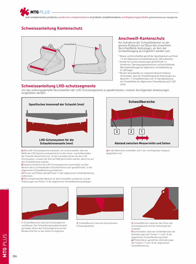
Schweissanleitung LHD-schutzsegmenteUm das ordnungsgemäße Verschweißen der LHD-Schutzsegmente zu gewährleisten, müssen die folgenden Anweisungen eingehalten werden:
Specific inside bucket (mm)
LHD system inside bucket (mm)Center of the lip towards the corners
Welding areas
3 2 1
Spezifisches Innenmaß der Schaufel (mm)Schweißbereiche
Abstand zwischen Messermitte und SeitenLHD-Schutzsystem für die Schaufelinnenseite (mm)
a) Alle LHD-Schutzsegmente aufsetzen, um sicherzustellen, dass die Maße des LHD-Systems entsprechend mit den Innen- und Außenmaßen der Schaufel übereinstimmen. Ist die Innenseite kürzer als das LHD-Schutzsystem, müssen die Teile auf Maß geschnitten werden, damit sie auf das Schaufelmesser passen.b) Soweit erforderlich die LHD-Schutzsegmente zuschneiden und den Bereich des zu schneidenden Schutzelements zuvor gemäß Punkt 1.6 der allgemeinen Schweißanleitung vorwärmen.c) Formen und Platten gemäß Punkt 1.5 der allgemeinen Schweißanleitung vorbereiten.d) Den entsprechenden Bereich vor dem Schweißen vorwärmen und die Anweisungen aus Punkt 1.6 der allgemeinen Schweißanleitung befolgen.
e) In den Bereichen schweißen, die in der nachfolgenden Sequenz dargestellt sind:
2. Schweißbereich zwischen benachbarten Schutzsegmenten.
3. Schweißbereich zwischen den Ecken der Schutzsegmente und der Seitenwand der Schaufel.f) Sicherstellen, dass der Schweißprozess die Anforderungen der Punkte 1.7 und 1.8 der allgemeinen Schweißanleitung erfüllt.g) Prüfverfahren gemäß den Anforderungen der Punkte 1.7 und 1.8 der allgemeinen Schweißanleitung.
1. Schweißbereiche zwischen Schutzsegment und Messer. Den Schweißvorgang abwechselnd auf beiden Seiten des Schutzsegments von der Messermitte her zu den Seiten hin beginnen.
Schweissanleitung Kantenschutz
Anschweiß-KantenschutzVor Aufnahme der Schweißarbeiten ist der genaue Einbauort auf Basis des erwarteten Verschleißbilds festzulegen, an dem der Schweißvorgang durchgeführt werden soll.
* Messer und Verschleißteil gemäß den Spezifikationen aus Punkt 1.5. der Allgemeinen Schweißanleitung (S. 260) vorbereiten.
* Vorwärmen und den Anweisungen gemäß Punkt 1.6. Vorwärmen, Übertragungstemperaturen und anschließende Wärmebehandlungen der Allgemeinen Schweißanleitung (S. 260) folgen.
* Mit dem Verschweißen im markierten Bereich fortfahren. Sicherstellen, dass der Schweißvorgang die Anweisungen aus Abschnitt 1.7. Schweißtechniken und 1.8. Nachbearbeitung der Schweißnähte der Allgemeinen Schweißanleitung (S. 262) erfüllt.
Schweißnähte

MTGPLUSand complementary products y productos complementarios et produits complémentaires und Ergänzungsprodukte дополнительных продуктов
307 MTG
PLU
S
УСТАНОВКА ПРИВАРНЫХ ЗАЩИТНЫХ СЕГМЕНТОВ ПДМЧтобы правильно выполнить установку и сварку защитных сегментов ПДМ, выполняйте инструкции, приведенные ниже:
a) Поместите все защиты ПДМ на нож, чтобы определить, надлежащим ли образом размеры защит соответствуют внутренной ширине и толщине боковой передней стенки ковша. Если внутренняя ширина ковша имеет меньший размер, чем у защитных сегментов системы ПДМ, потребуется выполнить подрезку некоторых деталей для обеспечения соответствия конкретному ножу внутри ковша.b) Если имеется потребность в подрезке защит ПДМ, необходимо подогреть зону защитных сегментов, подлежащих подрезке, в соответствии с положениями раздела 1.6. Подрезка должна проводиться с формированием фаски, подобной предыдущей, для обеспечения правильного выполнения процесса сварки.c) Подготовьте литую деталь и нож в соответствии с разделом 1.5 общих инструкций по сварке.d) Прежде чем начать технологический процесс сварки, необходимо выполнить предварительный нагрев и следовать указаниям, приведенным в разделе 1.6 общих инструкций по сварке.
e) Переходите к сварному шву в показанных областях согласно приведенной ниже последовательности.
Specific inside bucket (mm)
LHD system inside bucket (mm)Center of the lip towards the corners
Welding areas
3 2 1
Специальная ширина внутри ковша (мм)Зоны сварки
Центр ножа по отношению к угламСистема ПДМ внутри ковша (мм)
2. Зона сварки между соседними защитными сегментами.
3. Зона сварки между угловым защитным сегментом и боковой стенкой.f) Убедитесь в том, что метод сварки соответствует требованиям разделов 1.7 и 1.8 общих инструкций по сварке.g) Переходите к операциям контроля в соответствии с положениями раздела 1.9 общих инструкций по сварке.
1. Зоны сварки между защитными сегментами и ножом (режущей кромкой). Запуск происходит от центра ножа к углам и по обе стороны защитного сегмента.
ПРИВАРКА УГЛОВЫХ ЗАЩИТ
Инструкция по приварке угловых защитПеред началом сварки определите точное место приварки.
* Подготовьте нож и GET в соответствии с техническими требованиями пункта 1.5 Общей инструкции по сварке (стр. 264).
* Выполните предварительный нагрев и следуйте указаниям, приведенным в пункте 1.6. Предварительный нагрев, межваликовая температура и термообработка после сварки — в соответствии с Общей инструкцией по сварке (стр. 264).
* Выполните сварку на требуемом месте. Процесс сварки должен соответствовать требованиям раздела 1.7 «Методы сварки» и 1.8 «Завершение технологического процесса сварки» Общей инструкции по сварке (стр. 266).
Сварные швы

MTGPLUSand complementary products y productos complementarios et produits complémentaires und Ergänzungsprodukte дополнительных продуктов
308MTG
PLU
S
Welding instructions
GENERAL INSTRUCTIONS
Cleaning and preliminary preparation First of all, clean the parts to weld. The target is to remove grea-ses, oxides and other elements which can produce blowholes in the welding stage or another problems. To do this in the right way, use a metallic brush or light grinding.
PreheatingIts principal target is to prevent cracks. To avoid them, preheat and keep the area to be weld, between 140-180ºC. We recom-mend to use a gas torch, and control temperature with tempers-tilks or contact or radiation pyrometers.
Maximum Temperature and final check During the welding process, do not go over 250ºC, except the direct affected parts. The best method to keep the temperature within these limits, is to space each run.
When finishing the welding, it is essential to check the quality of the surface of the filler material and the absence of defects. The surface of beads must be as flat and regular as possible. Grind the irregularities, avoiding parallel grinding lines to the beads.
Covered electrode procedureIf you use covered electrodes, we recommend to use basic cove-red electrodes with a low-hydrogen content.
Diameter: use the bigger diameter as possible, 6 mm is suitable.Types: UNE-EN 499 E 42 B or UNE-EN 499 E 46 B; AWS A5.1 E-7016 or AWS A5.1 E-7018.Amperage and Polarity: follow manufacturer’s instructions.
Weld must be done with short beads and a maximum oscillation of three times the diameter of the electrode. Completely remove the slags and lightly hammer the bead to reduce tensions after each run.
Basic cover absorbs humidity. To avoid this, we recommend to stock electrodes in the original packaging hermetically sealed. Once opened, keep them heated within 65-150ºC.
GMAW procedure (Gas Metal Arc Welding)When it is done with gaseous protection, for moderate thickness and requireme ding, we recommend to use welding wire with solid thread. For high thickness and high requirement welding, use welding wire of tubular thread (Flux-core).
• Welding wire of solid thread Diameter: 1,6 mm (maximum recommended) Types: UNE-EN 440 type G 46 M or G 50 M; ASME/AWS ER 70
S-6; DIN 8559 SG2; and equivalents. Gas protection flow: 12-18 liters per minute.
• Welding wire of tubular thread (Flux-core) Types: ASME/AWS ER 70 T1 (rutile type); ASME/AWS E 70 T5
(basic type); DIN 8559.
With both types of welding wire, the welding must be done with a maximum oscillation of 10 mm. Lightly hammer the bead to avoid residual stresses after each run. It is very important to avoid draughts to protect the gas.
For the highest thickness and requirement welding, use welding wire of tubular thread (Flux-core) with low-hydrogen content, type DIN SG B1 C5254.
FLUSH ADAPTERS
Besides the general instructions...
Previous preparation Before starting to weld, ensure its right positioning to the blade.
ProcedurePut the adapter on the blade to ensure its right fitting with the lip of the blade. Do tack welds in the adapter in the right position.
• Welding the upper part Position the bottom bead by half a leg and go backwards until
you reach the same level on the opposite side. (Fig. A, num. 1). Continue from the edges of the lip until joining the previous bead. (num. 2). Carry out the same operation on the other side. (num. 3).
Make alternative runs repeating the same process until the cha-mfer cover thickness is more than 1 mm. If the chamfer does not reach the frontal edge of the blade, weld in this zone with beads of equal thickness. Make non-equal beads. The longer part must be on the blade.
• Welding the lower part Weld the lower part, from the adapter to the edge of the lip, as
thick as the superior beads, never less.
Fig. A. Flush adpaters
1
2
3
Fig. B. Two strap adapters
1
2
3

MTGPLUSand complementary products y productos complementarios et produits complémentaires und Ergänzungsprodukte дополнительных продуктов
309 MTG
PLU
S
TWO STRAP ADAPTERS
Besides the general instructions...
ProcedurePut the adapter on the blade to ensure its right fitting with the lip of the blade. Do tack welds in the adapter in the right position.
• Welding the upper strap Position the bottom bead by half a leg and go welding bac-
kwards until you reach the same level on the opposite side (Fig. B, num. 1). Continue from the edges of the lip until joi-ning the previous bead (num. 2 and 3).
Above all, make sure not to weld in the front side of the lip. It is necessary to start welding 15-25 mm (depending on the sizes) from the edge of the blade. Repeat the same process until the chamfer cover thickness is more than 1 mm. Remember to weld thicker beads in the blade.
• Welding the lower strap Weld the lower strap, starting 15-25 mm from the edge of the
blade backwards the strap. Go on making beads until comple-ting the welding.
Final surface must be flat or slightly convex. The bead must be a little bit thicker on the side of the blade.
UNIVERSAL ADAPTERS
Besides the general instructions...
ProcedurePut the adapter on the blade to ensure its right fitting with the lip of the blade. Do tack welds in the adapter in the right position.
• Welding the long lower strap Weld the lower strap starting by half a lower strap until rea-
ching the same level in the opposite side (Fig. C, num. 1).
Then weld starting 15-25 mm (depending on the size.from the edge of the blade backwards the strap completing the welding). Watch out, not to weld the edge of the blade (num. 2 and 3). Repeat the same process until the chamfer cover thickness is more than 1 mm.
• Increasing the thickness of the frontal part In the front side near the the lip of the blade in a length within
40-80 mm (depending on the size), increase the thickness of the weld bead until almost reaching the thickness in the back side of the strap. To do this, make alternative beads on both sides, doing a gradual transition between both thickness. Make non-equal beads. The thicker part must be on the blade.
• Welding the short strap Weld the short strap, starting 15-25 mm from the edge until
completing the bead on the other side. It has to be done until reaching a thickness similar to the thicker part of the long strap.
Final surface must be flat or slightly convex. The bead must be a little bit thicker at the edge of the blade.
LIP SHROUDS
Welding should be done following strictly the instructions he-reafter in order to avoid any lip failure.
Welding should be done using basic electrodes: AWS E 7016 E 7018, NF E 434/3B, DIN 1913 E 51 43 B10 our E 51 54B 102G. 1. Locate shrouds on the lip. (Shroud bevel edge rests on lip be-
vel edge.)2. Tack shrouds on the lip.3. Preheat shrouds and lip at 95ºC. In cold conditions (am-
bient temperature below 5ºC) preheat between 150ºC and 175ºC.
4. Start welding “X” mm (minimum) away from shroud edge. (“X” depending on shroud width.)
SHROUD WIDTH “A” DIMENSIONS “X”
150 up to 200 mm 20 mm 200 up to 300 mm 30 mm 300 up to 500 mm 40 to 50 mm
The weld strip must have the same thickness throughout its length. Weld strips must be done in the upper side and the lower side of the shroud.
5. Grind weld trip ends to avoid stress concentration.
Fig. C. Universal adapters
1
2
3
Fig. D. Shrouds
MTGPLUSand complementary products y productos complementarios et produits complémentaires und Ergänzungsprodukte дополнительных продуктов
310MTG
PLU
S
Normas de soldadura
INSTRUCCIONES GENERALES
Limpieza y preparación previa En primer lugar, limpie las piezas que hay que soldar. El obje-tivo es eliminar la grasa, el óxido y otros elementos que pue-den originar sopladuras y desprendimiento de gases durante la soldadura. Para hacerlo de forma adecuada, utilice un cepillo metálico o haga un amolado ligero.
PrecalentamientoSu principal objetivo es evitar las grietas. Para ese fin, preca-liente y mantenga la zona que va a soldarse entre los 140 y los 180ºC. Recomendamos el empleo de una antorcha de gas y con-trolar la temperatura con lápices térmicos o con pirómetros de radiación o de contacto.
Temperatura máxima y comprobación final Durante el proceso de soldadura, no se deben superar los 250ºC excepto en las zonas directamente afectadas. El mejor método para mantener la temperatura dentro de estos límites es espa-ciar las pasadas.
Una vez finalizada la soldadura, es muy importante comprobar la calidad de la superficie del material de aportación y la ausen-cia de defectos. La superficie de los cordones debe ser lo más plana y regular posible. Amole las irregularidades, evitando las rayas paralelas al sentido del cordón.
Soldadura por arco con electrodo recubierto (SA-ER/SMAW)Si utiliza electrodos recubiertos, recomendamos el empleo de electrodos básicos con bajo contenido en hidrógeno.
Diámetro: Utilizando los electrodos de mayor diámetro posible para reducir el aporte térmico. Un diámetro de 6 mm. es ade-cuado.Tipos: UNE-EN 499 E 42 B o UNE-EN 499 E 46 B; AWS A5.1 E-7016 o AWS A5.1 E-7018Amperaje y polaridad: Siga las instrucciones del fabricante.
La soldadura debe realizarse con cordones cortos y una oscila-ción máxima de tres veces el diámetro del electrodo. Elimine las escorias por completo y martillee ligeramente el cordón para reducir las tensiones después de cada pasada.
El recubrimiento básico absorbe la humedad. Para evitarlo, re-comendamos almacenar los electrodos en el envoltorio original cerrado herméticamente. Una vez abierto, manténgalos a una temperatura de entre 65 y 150ºC.
Soldadura por arco con protección por gas (SAG / GMAW)Para soldadura continua con gas protector utilizar hilo macizo para espesores pequeños y medianos. Para grandes espesores utilice hilo tubular (Flux core).
• Hilo macizo Diámetro: 1,6 mm (máximo) Tipos: UNE-EN 440 tipo G 46 M o G 50 M; ASME/AWS ER 70
S-6; DIN 8559 SG2; y equivalentes. Flujo de protección de gas: 12-18 litros por minuto.
• Hilo tubular (Flux-core) Diámetro: 2,4 mm (máximo) Tipos: ASME/AWS ER 70 T1 (tipo rutilo); ASME/AWS E 70 T5
(tipo básico); DIN 8559.
Soldar con una oscilación máxima de 10 mm. Martillee ligera-mente el cordón para atenuar tensiones residuales después de cada pasada. Con hilo tubular, eliminar escoria entre pasadas. Evitar corrientes de aire para mantener la protección del gas.
Para grandes espesores de aportación y elevadas solicitaciones, elegir hilo tubular básico con bajo contenido de hidrógeno certi-ficado tipo DIN SG B1 C5254 ó equivalentes.
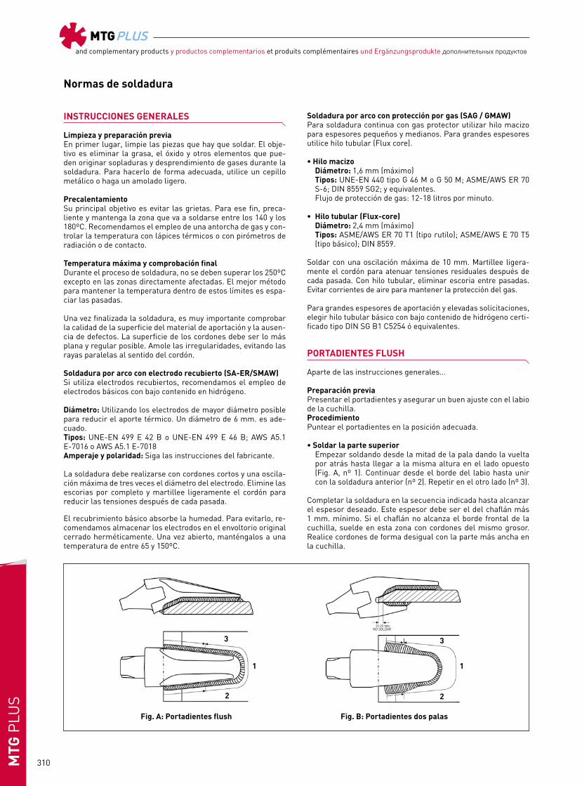
PORTADIENTES FLUSH
Aparte de las instrucciones generales…
Preparación previa Presentar el portadientes y asegurar un buen ajuste con el labio de la cuchilla.ProcedimientoPuntear el portadientes en la posición adecuada.
• Soldar la parte superior Empezar soldando desde la mitad de la pala dando la vuelta
por atrás hasta llegar a la misma altura en el lado opuesto (Fig. A, nº 1). Continuar desde el borde del labio hasta unir con la soldadura anterior (nº 2). Repetir en el otro lado (nº 3).
Completar la soldadura en la secuencia indicada hasta alcanzar el espesor deseado. Este espesor debe ser el del chaflán más 1 mm. mínimo. Si el chaflán no alcanza el borde frontal de la cuchilla, suelde en esta zona con cordones del mismo grosor. Realice cordones de forma desigual con la parte más ancha en la cuchilla.
Fig. A: Portadientes flush
1
2
3
Fig. B: Portadientes dos palas
1
2
3
NO SOLDAR

MTGPLUSand complementary products y productos complementarios et produits complémentaires und Ergänzungsprodukte дополнительных продуктов
311 MTG
PLU
S
• Soldar la parte inferior Suelde la parte inferior, desde el adaptador hasta el borde
del labio con un grosor mayor al de los cordones superiores, nunca inferior.
PORTADIENTES DE DOS PALAS
Aparte de las recomendaciones de las instrucciones generales...
ProcedimientoColoque el adaptador en la cuchilla y asegure el buen encaje con el labio de la cuchilla. Puntee el adaptador en la posición adecuada.
• Soldadura de la pala superior Empezar soldando desde la mitad de la pala superior hasta
la misma altura del lado opuesto (Fig. B, nº 1). A continuación soldar desde unos 15-25 mm. del borde de la cuchilla hasta unir con el cordón anterior. No soldar en la zona frontal del labio (nº 2). Soldar el cordón del lado opuesto (nº 3).
Repetir el mismo proceso hasta completar el espesor deseado del metal de aportación. El cordón debe cubrir todo el chaflán previsto al efecto más 1 mm. como mínimo. Los cordones deben ser desiguales, con la parte más ancha en la cuchilla. • Soldadura de la pala inferior Suelde la pala inferior, comenzando a unos 15-25 mm del filo
de la cuchilla hasta el centro de la pala. Ir depositando cordo-nes alternativamente hasta completar la soldadura.
PORTADIENTES UNIVERSALES
Aparte de las recomendaciones de las instrucciones generales...
ProcedimientoPresentar el portadientes y asegurar su buen ajuste con el labio de la cuchilla. Puntear en la posición adecuada.
• Soldadura de la pala larga inferior Empezar soldando desde el centro de la pala inferior hasta la
misma altura del lado opuesto (Fig. C, nº 1). A continuación soldar desde unos 15-25 mm (según tallas) del borde de la cuchilla hasta unir con el cordón anterior (nº 2). Repetir en el lado opuesto (nº 3). Repetir esta secuencia hasta completar el cordón. El metal de aportación debe cubrir todo el chaflán del portadientes más 1 mm. mínimo.
• Aumento del espesor del cordón En la zona frontal cercana al labio de la cuchilla y en una lon-
gitud de 40-80 mm. (según tallas) hay que aumentar el espe-sor del cordón hasta casi doblar el espesor de la parte trase-ra de la pala. La transición entre ambos espesores debe ser gradual. Efectúe cordones desiguales, con la parte más ancha sobre la cuchilla.
• Soldadura de la pala corta superior Soldar ahora la pala superior, empezando a unos 15-25 mm.
del borde de la cuchilla hasta completar el cordón en el otro lado. Repetir hasta alcanzar un espesor semejante al de la parte frontal de la pala inferior.
PROTECTORES DE CUCHILLA
Es importante seguir las instrucciones siguientes para la sol-dadura de protectores con el fin de evitar la aparición de fisuras en la cuchilla.
La soldadura debe ser efectuada con electrodos del tipo: AWS E7016 y E7018 o hilo macizo de los tipos AWS E70S o AWS E70T1. 1. Posicionar los protectores sobre la cuchilla.(El bisel del pro-
tector sobre el bisel de la cuchilla.)2. Puntear los protectores sobre la cuchilla.3. Precalentar el protector y cuchilla a 95ºC. En épocas frías
(temperatura ambiente inferior a 5ºC) precalentar entre 150ºC y 175ºC.
4. Comenzar la soldadura a “X” mm (mínimo) del borde del pro-tector dependiendo de la longitud de este.
ANCHO DEL PROTECTOR “A” DIMENSION “X”
De 150 hasta 200 mm 20 mm De 200 hasta 300 mm 30 mm De 300 hasta 500 mm 40 a 50 mm
El cordón de soldadura debe tener el mismo grosor en toda su longitud. Realizar cordones de soldadura en la parte supe-rior e inferior del protector.
5. Amolar los extremos del cordón para evitar la concentración de tensiones.
Fig. C. Portadientes universal
1
2
3
Fig. D. Protectores
NO SOLDAR
MTGPLUSand complementary products y productos complementarios et produits complémentaires und Ergänzungsprodukte дополнительных продуктов
312MTG
PLU
S
Normes de soudure
INSTRUCTIONS GÉNÉRALES
Nettoyage et préparation préalableNettoyer tout d’abord les pièces à souder. Pour éliminer la graisse, la rouille et tout autre élément pouvant causer des soufflures et des dégagements de gaz pendant la soudure. Utili-ser pour cela une brosse métallique ou faire un léger meulage.
PréchauffageLe principal objectif du préchauffage, est d’éviter les fissures. Pour ce faire, faire un préchauffage et maintenir la zone à sou-der entre 140 et 180ºC. Nous recommandons l’utilisation d’un chalumeau à gaz et le contrôle de la température avec des cra-yons thermiques ou des pyromètres à radiation ou à contact.
Température maximum et vérification finale Pendant le processus de soudure, il ne faut pas dépasser 250ºC sauf sur les zones directement affectées par la soudure. Le meilleur moyen de conserver la température dans ces limites, est d’espacer les passes.
Une fois la soudure terminée, il est très important de vérifier la qualité de la surface du matériel d’apport et l’absence de dé-fauts. La surface des cordons doit être la plus plate et la plus régulière possible. Meuler les irrégularités, en évitant les rayu-res parallèles au sens du cordon.
Soudure à l’arc avec électrode enrobée (SA-ER/SMAW)Si on utilise des électrodes enrobées, il est recommandé l’emploi d’électrodes basiques à enrobage à faible teneur en hydrogène.
Types d’électrode aux normes: UNE -EN 499, E 42 B ou UNE-EN 499 E 46 B; AWS A5.1 E-7016 ou AWS A5.1 E-7018.Il est important d’utiliser des électrodes ayant le plus grand dia-mètre possible pour réduire l’apport thermique. Un diamètre de 6 mm est correct.Ampérage et polarité: suivre les instructions du fabricant.
La soudure doit être réalisée avec des cordons courts et une os-cillation maximum de trois fois le diamètre de l’électrode. Élimi-ner complètement les scories et marteler légèrement le cordon pour réduire les tensions après chaque passe.
L’enrobage basique absorbe l’humidité. Pour éviter cela, nous recommandons de garder les électrodes dans leur emballage d’origine hermétiquement fermé. Après l’ouverture, les garder
à une température entre 65 et 150ºC.
Soudure à l’arc sous protection gazeuse (SAG/GMAW)Pour la soudure continue à gaz de protection, utiliser du fil mas-sif pour les épaisseurs petites et moyennes. Pour de grandes épaisseurs, utiliser du fil tubulaire (Flux core).
• Fil massif Diamètre recommandé: maximum 1,6 mm. Types: UNE-EN 440 type G 46 M ou G 50 M; ASME/AWS ER 70
S-6; DIN 8559 SG2; et équivalents. Flux de gaz de protection: 12-18 litres/minute.
• Fil tubulaire (Flux core) Diamètre recommandé: maximum 2,4 mm. Types: ASME/AWS; ER 70 T1 (type rutile); ASME/AWS; E 70 T5
(type basique); SG B1 C 5254 (DIN 8559).
Souder avec une oscillation maximum de 10 mm. Marteler lé-gèrement le cordon pour atténuer les tensions résiduelles après chaque passe. Avec du fil tubulaire, éliminer les scories entre les passes. Éviter les courants d’air pour conserver la protection du gaz.
Pour de grandes épaisseurs d’apport et des sollicitations éle-vées, choisir du fil tubulaire basique à faible teneur en hydrogè-ne homologué type DIN SG B1 C5254 ou équivalents.
PORTE-DENTS FLUSH À SOUDER
En plus des instructions générales...
Préparation préalable Présenter le porte-dents et assurer un bon ajustage avec la lèvre de la lame.
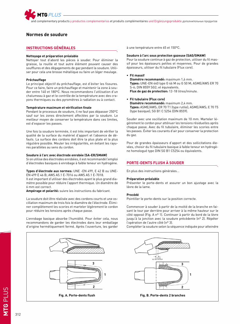
ProcédéPointiller le porte-dents sur la position correcte.
Commencer à souder à partir de la moitié de la branche en fai-sant le tour par derrière pour arriver à la même hauteur sur le côté opposé (Fig. A nº 1). Continuer à partir du bord de la lèvre jusqu’à la jonction avec la soudure précédente (nº 2). Répéter l’opération de l’autre côté (nº 3).Compléter la soudure selon la séquence indiquée pour atteindre
Fig. A. Porte-dents flush
1
2
3
Fig. B. Porte-dents 2 branches
1
2
3
NE PAS SOUDER

MTGPLUSand complementary products y productos complementarios et produits complémentaires und Ergänzungsprodukte дополнительных продуктов
313 MTG
PLU
S
l’épaisseur voulue. Cette épaisseur doit être celle du chanfrein plus 1 mm comme minimum. Si le chanfrein n’atteint pas le bord frontal de la lame, souder dans cette zone avec des cor-dons de même épaisseur. Réaliser des cordons inégaux avec la partie plus large sur la lame.
Souder la partie inférieure, depuis le porte-dents jusqu’au bord de la lèvre avec une épaisseur plus grande que celle des cordo-ns supérieurs, jamais inférieure.
PORTE-DENTS 2 BRANCHES
En plus des instructions générales...
ProcédéPlacer le porte-dents sur la lame et assurer un bon ajustage avec la lèvre de la lame. Pointiller le porte-dents sur la position co-rrecte.
• Soudure de la branche supérieure Commencer à souder à partir de la moitié de la branche su-
périeure jusqu’à la même hauteur du côté opposé (Fig. B, nº 1). Ensuite souder en partant de 15-25 mm du bord de la lame jusqu’à la jonction avec le cordon précédent. Ne pas souder sur la zone frontale de la lèvre (Fig. B nº 2). Souder le cordon du côté opposé (nº 3).
Répéter le même procédé pour obtenir l’épaisseur voulue du métal d’apport. Le cordon doit couvrir tout le chanfrein prévu à cet effet plus 1 mm comme minimum. Les cordons doivent être inégaux avec la partie plus large sur la lame.
• Soudure de la branche inférieure Souder la branche inférieure, en commençant à 15-25 mm
du fil de la lame jusqu’au centre de la branche. Poser des cordons alternativement pour compléter la soudure.
PORTE-DENTS UNIVERSELS
En plus des instructions générales...
ProcédéPrésenter le porte-dents et assurer un bon ajustage avec la lèvre de la lame. Pointiller sur la position correcte.Commencer à souder depuis le centre de la branche inférieure jusqu’à la même hauteur du côté opposé (Fig. C, nº 1). Ensuite souder à partir de 15-25 mm (selon les tailles) du bord de la
lame jusqu’à la jonction avec le cordon précédent (nº 2). Répéter sur le côté opposé (nº 3). Répéter cette séquence pour complé-ter le cordon. Le métal d’apport doit couvrir tout le chanfrein du porte-dents plus 1 mm comme minimum.
Dans la zone frontale près de la lèvre de la lame et sur une longueur de 40-80 mm (selon les tailles), il faut augmenter l’épaisseur du cordon de manière à presque doubler l’épaisseur de la partie arrière de la branche. La transition entre des deux épaisseurs doit être graduelle. Faire des cordons inégaux avec la partie plus large sur la lame.
Souder maintenant la branche supérieure, en commençant à par-tir de 15-25 mm du bord de la lame jusqu’à la jonction avec le cor-don sur l’autre côté. Répéter l’opération pour atteindre la même épaisseur que sur la partie frontale de la branche inférieure.
BOUCLIERS DE LAME
Il est important de suivre les instructions suivantes pour souder des boucliers afin d’éviter l’apparition de fissures sur la lame.
La soudure doit être effectuée avec des électrodes du type: AWS E7016 et E7018 ou fil massif des types AWS E70S ou AWS E70T1.
1. Placer les boucliers sur la lame. (Le biseau du bouclier sur le biseau de la lame).
2. Pointer les boucliers sur la lame.3. Préchauffer le bouclier et la lame à 95º C. Lors de périodes
de basses températures (température ambiante inférieure à 5º C), préchauffer entre 150º C et 175º C.
4. Commencer la soudure à « X » mm (minimum) du bord du protecteur selon sa longueur.
LONGUEUR DU BOUCLIER “A” DIMENSION “X”
Entre 150 et 200 mm 20 mm Entre 200 et 300 mm 30 mm Entre 300 et 500 mm Entre 40 et 50 mm
Le cordon de soudure doit être régulier et avoir la même épaisseur sur toute la longueur à souder. Il est important de réaliser des cordons de soudure dans les parties supérieure et inférieure du protecteur.
5. Meuler les extrémités du cordon pour éviter la concentration de tensions.
Fig. C. Porte-dents universels
1
2
3
NE PAS SOUDER
Fig. D. Boucliers

MTGPLUSand complementary products y productos complementarios et produits complémentaires und Ergänzungsprodukte дополнительных продуктов
314MTG
PLU
S
Schweißanleitungen
ALLGEMEINE ANLEITUNG
Reinigung und Vorbereitungen Man reinigt zuerst die Teile, die geschweißt werden sollen. Der Zweck ist Fett, Rost und andere Elemente zu beseitigen, die während des Schweißens Spritzer oder Gasdämpfe verur-sachen können. Um das richtig auszuführen, benützt man eine Drahtbürste oder schleift es leicht ab.
VorwärmungDas Hauptziel ist Risse zu vermeiden. Dazu wärmt man die Stelle die geschweißt wird zwischen 140 und 180º auf und man behält die Temperatur bei. Wir empfehlen den Gebrauch eines Schweißbrenners und die Temperaturkontrolle führt man mit einem Thermostift, einem Strahlungspyrometer oder einem Kontaktpyrometer aus.
Höchsttemperatur und EndprüfungWährend des Schweißvorgangs dürfen 250º C an den betreffen-den Stellen nicht überschritten werden. Die beste Methode um die Temperatur in diesen Grenzen zu halten, ist die Durchgänge zu verlängern.
Nach der Schweißung ist es sehr wichtig die Qualität der Ober-fläche des Zusatzmaterials zu prüfen und kontrollieren, daß keine Fehler auftreten. Die Oberfläche der Schweißnaht muß so flach und gleichmäßig wie möglich sein. Unregelmäßigkeiten müssen abgeschliffen werden und parallele Linien in Schweiß-nahtrichtung müssen vermieden werden.
Lichtbogenschweißen mit beschichteten Elektroden (SA-ER/SMAW)Wenn beschichtete Elektroden benützt werden, empfehlen wir den Gebrauch von basischen Elektroden mit einem niedrigen Wasserstoffgehalt.
Elektrodentypen nach: UNE-EN 499, E 42 oder UNE-EN 499 E 46 B; AWS A5.1 E-7016 oder AWS A5.1 E-7018.Der Gebrauch von Elektroden mit größtmöglichstem Durch-messer vermindert die Wärmeeinbringung. Ein zweckmäßig Durchmesser ist 6 mm.Stromstärke und Polarität: die Anweisungen des Herstellers befolgen.
Die Schweißung muß mit kurzen Nähten ausgeführt werden und mit einer Oszillation von höchstens dem Dreifachen des Elek-trodendurchmesser. Man muß die Schlacke vollständig beseiti-gen und nach jedem Durchgang muß die Naht leicht gehämmert werden, um die Spannungen zu vermindern.
Die basische Beschichtung nimmt Feuchtigkeit auf. Um dies zu vermeiden, empfehlen wir die Elektroden in ihrer Original-verpackung hermetisch verschlossen aufzubewahren. Einmal geöffnet müssen sie bei Temperaturen zwischen 65º und 150º aufbewahrt werden.
Lichtbogenschweißen mit Schutzgas (SAG/GMAW)Für Dauerschweißen mit Schutzgas wird ein Massivdraht für kleinere und mittlere Dicken benutzt. Für größere Dicken wird Rohrdraht benutzt (Flux-core).
• Empfohlene Drahttypen gemäß: Typen: UNE-EN 440 Typ G 46 oder G 50 M; ASME/AWS; ER 70
S-6 DIN 8559 SG2; und ähnliche. Durchmesser höchstens: 1,6 mm. Schutzgasdurchfluß: 12 - 18 Liter pro Minute.
• Rohrdraht (Flux-core) Typen: ASME/AWS; ER 70 T1 (Typ Rutil); ASME/AWS; E 70 T 5
(Typ basisch); SG B1 C 5254 (DIN 8559). Empfohlener Durchmesser: höchstens 2,4 mm.
Schweißen mit Oszillationen von höchstens 10 mm. Die Naht muß nach jedem Durchgang leicht gehämmert werden, um Restspan-nungen zu vermindern. Bei Rohrdraht muß die Schlacke zwis-chen den Durchgängen beseitigt werden. Luftzug muß vermieden werden, damit der Gasschutz aufrecht erhalten bleibt.
Bei großen Dicken von Zusatzmaterial und hoher Beanspru-chung muß ein zertifizierter basischer Rohrdraht mit einem niedrigen Wasserstoffgehalt Typ DIN SG B1 C5254 oder ähnlich gewählt werden.
ZAHNHALTER FLUSH
Neben den allgemeinen Anleitungen...
Vorbereitungen Den Zahnhalter hinhalten und sich versichern, daß er gut an die Lippe des Messers paßt.
VerfahrenDie Zahnhalterung in der richtigen Position mit Punkten ans-chweißen. Man fängt in der Mitte des Schenkels an und schweißt rundherum bis man auf der gegenüberliegenden Seite wieder an die gleiche Stelle kommt (Bild A Nr. 1). Von der Messerkante bis zum Zusammenschluß mit der vorhergehenden Schweiß-naht weiterfahren (Nr. 2). Das gleiche auf der anderen Seite
Fig. A. Zahnhalter flush
1
2
3
Fig. B. Zahnhalter mit zwei Schenkel
1
2
3
NICHT ANSCHWEISSEN

MTGPLUSand complementary products y productos complementarios et produits complémentaires und Ergänzungsprodukte дополнительных продуктов
315 MTG
PLU
S
Fig. C. Universalzahnhalter
1
2
3
Fig. D. Messer Schutzsegment
NICHT ANSCHWEIßEN
wiederholen (Nr. 3). Die Schweißung im gleichen Ablauf wie beschrieben bis zur gewünschten Dicke ergänzen. Diese Dic-ke muß wie die Schrägkante sein und mindestens noch 1 mm mehr. Wenn die Schrägkante nicht bis zur vorderen Messerkan-te reicht, schweißt man an dieser Stelle mit Schweißnähten der gleichen Dicke. Man muß ungleiche Schweißnähte anfertigen, mit dem breitesten Teil am Messer.
Man schweißt den unteren Teil vom Zahnhalter bis zum Rand der Lippe mit einer größeren Dicke als die oberen Schweißnäh-te, nie weniger.
ZAHNHALTER MIT ZWEI SCHENKEL
Neben den allgemeinen Anleitungen...
VerfahrenMan bringt den Zahnhalter am Messer an und versichert sich, daß er richtig an die Lippe des Messers paßt. Den Zahnhalter in der richtigen Position mit Punkten anschweißen.
• Schweißnaht des oberen Schenkels Man beginnt mit der Schweißnaht in der Mitte des oberen
Schenkels und schweißt bis zur gleichen Stelle auf der ge-genüberliegenden Seite (Bild B, Nr. 1). Nachher schweißt man 15-25 mm von der Messerkante entfernt bis zum Zusam-menschluß mit der vorherigen Schweißnaht. Die Frontalzone der Lippe wird nicht geschweißt (Bild B, Nr. 2). Die Schweiß-naht auf der gegenüberliegenden Seite schweißen (Nr. 3).
Diesen Vorgang wiederholen bis die gewünschte Dicke des Zu-satzmaterials erreicht ist. Die Schweißnaht muß die dafür vor-gesehenen Schrägkante überdecken und mindestens noch 1 mm mehr. Die Schweißnähte müssen ungleich sein und mit dem breitesten Teil am Messer. • Schweißnaht des unteren Schenkel Man schweißt den unteren Schenkel, indem man bei 15-25
mm von der Messerschneide entfernt beginnt und bis zur Mit-te des Schenkels schweißt. Die Schweißnähte abwechselnd anbringen bis die Schweißung komplett ist.
UNIVERSALZAHNHALTER
Neben den allgemeinen Anleitungen...
VerfahrenDen Zahnhalter hinhalten und sich versichern, daß er gut an die Lippe des Messers paßt. In der richtigen Position mit Punkten anschweißen.
Man beginnt mit der Schweißnaht in der Mitte des unteren Schenkels und schweißt bis zur gleichen Stelle auf der gegenü-berliegenden Seite (Bild C, Nr. 1). Nachher schweißt man 15-25 mm (je nach Größe) von der Messerkante entfernt bis zum Zu-sammenschluß mit der vorherigen Schweißnaht (Nr. 2). Dassel-be auf der gegenüberliegenden Seite wiederholen. (Nr. 3).
Diesen Ablauf wiederholen bis die Schweißnaht komplett ist. Das Zusatzmaterial muß die ganze Schrägkante des Zahnhal-ters decken und mindestens noch 1 mm mehr.
In der Frontalzone nahe der Lippe des Messers muß man in ei-ner Länge von 40-80 mm (je nach Größe) die Dicke der Schweiß-naht bis fast auf das Doppelte der Dicke der hinteren Stelle des Schenkels erhöhen. Der Übergang zwischen den beiden Dicken muß fließend sein. Man muß ungleiche Schweißnähte anferti-gen, mit dem breitesten Teil über dem Messer.
Man schweißt jetzt den oberen Schenkel indem man 15-25 mm von der Messerkante beginnt bis die Schweißnaht auf der anderen Seite vervollständigt ist. Man wiederholt das bis man eine ähnli-che Dicke wie im vorderen Teil des unteren Schenkels erreicht.
MESSERSCHUTZSEGMENTE
Um die Entstehung von Rissen am Messer zu verhindern, sind bei der Schweißung der Schutzsegmente unbedingt folgende Anweisungen zu befolgen.
Die Schweißung ist mit Elektroden des Typs: AWS E7016 und E7018 oder Massivdraht des Typs AWS E70S oder AWS E70T1 durchzuführen.
1. Schutzsegment auf dem Messer positionieren (Schrägkante des Schutzsegments auf Schrägkante des Messers).
2. Schutzsegment auf dem Messer zentrieren.3. Schutzsegment und Messer auf 95ºC vorwärmen. In der kal-
ten Jahreszeit (Umgebungstemperatur unter 5ºC) auf 150ºC bis 175ºC vorwärmen.
4. In mind. „X“ mm Abstand vom Rand des Schutzsegments und entsprechend seiner Länge mit der Schweißung beginnen.
LÄNGE „A“ VOM SCHUTZSEGMENT ABSTAND „X“
150 bis 200 mm 20 mm 200 bis 300 mm 30 mm 300 bis 500 mm 40 bis 50 mm
Die Schweißnaht soll eine gleichmäßig Dicke über der ges-amten Länge haben. Auf der Ober- und Unterseite des Mes-serschutzsegments eine Schweißnaht erzeugen.
5. Die Enden der Schweißnaht abschleifen, um Spannungskon-zentrationen zu verhindern.

MTGPLUSand complementary products y productos complementarios et produits complémentaires und Ergänzungsprodukte дополнительных продуктов
316MTG
PLU
S
Welding instructions
Fig. A. Адаптеры, устанавливаемые вровень
1
2
3
Fig. B. Адаптеры с двойным обхватом
1
2
3
Инструкции по сварке
ОББЩИЕ ИНСТРУКЦИИ
Очистка и предварительная подготовкаПрежде всего очистите элементы, подлежащие сварке. Цель заключается в том , чтобы удалить консистентную смазку, оксиды и другие компоненты, которые могут привести к образованию свищей в процессе сварки или к другим проблемам. Чтобы сделать это правильно, используйте металлическую щетку или легкое шлифование.
Предварительный нагревЕго главной целью является предотвращение образования трещин. Чтобы избежать их, нагрейте зону сварки и поддерживайте ее температуру в диапазоне 140–180 ºC. Рекомендуется использовать газовую горелку и контролировать температуру с помощью термокарандаша либо контактного или радиационного пирометра.
Максимальная температура и окончательная проверкаВ процессе сварки не допускайте подъема температуры выше 250 ºС, за исключением элементов, на которые оказывается прямое воздействие. Лучшим способом поддержания температуры в этих пределах является выдержка паузы после каждого прохода.
По завершении сварки необходимо проверить качество поверхности наплавленного металла и отсутствие дефектов. Поверхность валиков шва должна быть плоской и равномерной, насколько это возможно. Зашлифуйте неровности, избегая нанесения параллельных линий шлифовки на шов.
Процедура с применением обмазанных электродовЕсли вы применяете обмазанные электроды, рекомендуется использовать электроды с основным покрытием с низким содержанием водорода.Диаметр: используйте как можно больший диаметр; подходит диаметр 6 мм. Типы: UNE-EN 499 E 42 B или UNE-EN 499 E 46; AWS A5.A E-7016 или AWS A5.1 E-7018.Сила тока и полярность: следуйте инструкциям производителя. Сварка должна выполняться с применением коротких валиков, максимальная амплитуда поперечных колебаний электрода не должна превышать трех диаметров электрода. После каждого прохода следует полностью удалять шлаки и слегка постукивать по валику для уменьшения остаточных напряжений.Основное покрытие впитывает влагу. Во избежание этого рекомендуется хранить электроды в оригинальной герметично запечатанной упаковке. После вскрытия упаковки храните электроды в нагретом состоянии при температуре 65–150 ºC.
Дуговая сварка металлическим электродом в средеинертного газа (GMAW)При сварке в среде защитного газа элементов с умеренной толщиной и обычными требованиями к сварке рекомендуется использовать сплошную сварочную проволоку. Для сварки элементов с большой
толщиной и высокими требованиями к сварке используйте проволоку с флюсовым сердечником.
• Сплошная сварочная проволока Диаметр: 1,6 мм (рекомендуемый максимум) Типы: UNE-EN 440 type G 46 M или G 50M ; ASME/AWS ER 70 S-6; DIN
8559 SG2; и аналогичные. Расход защитного газа: 12–18 л/мин.
• Сварочная проволока с флюсовым сердечником. Типы: ASME/AWS ER 70 T1 (рутиловый тип); ASME/AWS E 70 T5
(основной тип); DIN 8559. Для обоих типов сварочной проволоки сварка должно
выполняться с максимальной амплитудой колебаний электрода 10 мм. После каждого прохода следует слегка постукивать по валику, чтобы избежать возникновения остаточных напряжений. Для действия защиты, обеспечиваемой газом, очень важно не допустить возникновения сквозняков.
Для сварки элементов с очень большой толщиной и очень высокими требованиями к сварке используйте сварочную проволоку с флюсовым сердечником с низким содержанием водорода, типа DIN SG B1 C5254.
АДАПТЕРЫ, УСТАНАВЛИВАЕМЫЕ ВРОВЕНЬВ дополнение к общим инструкциям...
Предыдущая подготовкаПеред началом сварки обеспечьте правильное позиционирование адаптера относительно режущей кромки.
ПроцедураПоместите адаптер на режущую кромку, обеспечив его правильное сопряжение с краем режущей кромки. Выполните прихваточные сварные швы на адаптере в правильном положении.
• Сварка верхней части Выполните нижний валик до середины нижней части и двигайтесь
в обратном направлении, пока не достигнете того же уровня на противоположной стороне (рис. A. поз. 1). Продолжайте от края режущей кромки до соединения с предыдущим валиком (поз. 2). Выполните ту же операцию на другой стороне (поз. 3).
Выполняйте поочередные проходы, повторяя одинаковую процедуру до тех пор, пока перекрытие разделки не превысит 1 мм. Если разделка не доходит до переднего края режущей кромки, выполните сварку в этой зоне с помощью валиков одинаковой толщины. Валики должны иметь неодинаковые катеты. Более длинная сторона должна приходиться на режущую кромку.
• Сварка нижней части Приварите нижнюю часть, от адаптера к краю режущей кромки, делая
валики толщиной, равной толщине верхних валиков, не меньше.

MTGPLUSand complementary products y productos complementarios et produits complémentaires und Ergänzungsprodukte дополнительных продуктов
317 MTG
PLU
S
Fig. C. Универсальные адаптеры
1
2
3
Fig. D. Межзубьевые сегменты
АДАПТЕРЫ С ДВОЙНЫМ ОБХВАТОМ
В дополнение к общим инструкциям...
ПроцедураПоместите адаптер на режущую кромку, обеспечив его правильное сопряжение с краем режущей кромки. Выполните прихваточные сварные швы на адаптере в правильном положении.
• Сварка верхней части Выполните нижний валик до середины адаптера и двигайтесь
в обратном направлении, пока не достигнете того же уровня на противоположной стороне (рис. B, поз. 1). Продолжайте от краев режущей кромки до соединения с предыдущим валиком (поз. 2 и 3).
Прежде всего, не выполняйте сварку на передней стороне режущей кромки. Необходимо начинать сварку в 15–25 мм (в зависимости от размеров) от края режущей кромки. Повторяйте эту процедуру до тех пор, пока перекрытие разделки не превысит 1 мм. Помните, что больший катет должен располагаться на режущей кромке.
• Сварка нижней части Приварите нижнюю часть, начиная в 15–25 мм от края режущей
кромки и двигаясь назад вдоль нижней части адаптера. Выполняйте валики до завершения сварки.
Окончательная поверхность шва должна быть плоской или слегка выпуклой. Катет должен быть немного больше на стороне режущей кромки.
УНИВЕРСАЛЬНЫЕ АДАПТЕРЫ
В дополнение к общим инструкциям...
ПроцедураПоместите адаптер на режущую кромку, обеспечив его правильное сопряжение с краем режущей кромки. Выполните прихваточные сварные швы на адаптере в правильном положении.
• Сварка длинной нижней части Приварите нижнюю часть, двигаясь к середине нижней части и
обратно, пока не достигнете того же уровня на противоположной стороне (рис. C, поз. 1).
Затем выполните сварку, начав в 15–25 мм (в зависимости от размера) от края режущей кромки, двигаясь назад вдоль нижней части до завершения сварки). Будьте осторожны, не выполняйте сварку по краю режущей кромки (поз. 2 и 3). Повторяйте эту процедуру до тех пор, пока перекрытие разделки не превысит 1 мм.
• Увеличение толщины передней части На передней стороне около края режущей кромки на длине 40–
80 мм (в зависимости от размера) увеличьте толщину сварного шва почти до толщины задней стороны секции адаптера. Чтобы сделать это, поочередно выполните валики на обеих сторонах, делая постепенный переход между двумя толщинами. Валики должны иметь неодинаковые катеты. Более длинная сторона должна приходиться на режущую кромку.
• Сварка короткой части Приварите короткую часть, начиная в 15–25 мм от края режущей
кромки, до выполнения шва на другой стороне. Сварку следует выполнять до достижения толщины, равной толщине более толстой части на длинной стороне.
Окончательная поверхность шва должна быть плоской или слегка выпуклой. Катет должен быть немного больше на стороне режущей кромки.
МЕЖЗУБЬЕВЫЕ СЕГМЕНТЫ ДЛЯ ЗАЩИТЫ РЕЖУЩЕЙ КРОМКИ
Чтобы избежать повреждения края режущей кромки, сварка должна выполняться в строгом соответствии с инструкциями, приведенными ниже.
Сварка должна выполняться с использованием основных электродов: AWS E 7016 E 7018, NF E434/3B, DIN 1913 E 51 43 B10 или E 51 54B 102G.
1. Установите межзубьевые сегменты на режущую кромку. (Скошенный край межзубьевого сегмента опирается на скошенный край режущей кромки).
2. С помощью прихваточных швов зафиксируйте межзубьевые сегменты на режущей кромке.
3. Нагрейте межзубьевые сегменты и режущую кромку до 95 ºC. В холодных условиях (температура окружающей среды ниже +5 °С ) нагревайте до температуры 150 ºC–175 ºC.
4. Начните сварку на расстоянии X мм (минимум) от края межзубьевого сегмента. (Расстояние X зависит от ширины межзубьевого сегмента).
ШИРИНА МЕЖЗУБЬЕВОГО СЕГМЕНТА “A” РАЗМЕР “X”
150 - 200 мм 20 мм 200 - 300 мм 30 мм 300 - 500 мм 40 -50 мм
Сварной шов должен иметь одинаковую толщину по всей длине. Сварные швы должно быть выполнены на верхней стороне и на нижней стороне межзубьевого сегмента.
5. Зашлифуйте концы сварных швов, чтобы избежать концентрации напряжений.я.

MTG
PLU
SMTGPLUS
and complementary products y productos complementarios et produits complémentaires und Ergänzungsprodukte дополнительных продуктов