MT-S20 USER’S MANUAL - Global Sourcesp.globalsources.com/IMAGES/PDT/SPEC/533/K1050920533.pdfSetup...
20
MT-S20 USER’S MANUAL (Motor Alarm &Tracker) (Version 1.4)
Transcript of MT-S20 USER’S MANUAL - Global Sourcesp.globalsources.com/IMAGES/PDT/SPEC/533/K1050920533.pdfSetup...

MT-S20 USER’S MANUAL (Motor Alarm &Tracker)
(Version 1.4)
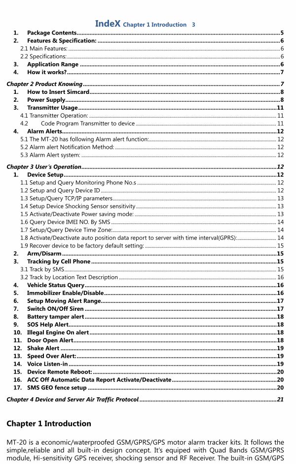
IndeX Chapter 1 Introduction 3 1. Package Contents .............................................................................................................................. 5 2. Features & Specification: ................................................................................................................. 6
2.1 Main Features: ................................................................................................................................................................... 6 2.2 Specifications: .................................................................................................................................................................... 6
3. Application Range ............................................................................................................................ 6 4. How it works? .................................................................................................................................... 7
Chapter 2 Product Knowing .......................................................................................................................... 7 1. How to Insert Simcard ...................................................................................................................... 8 2. Power Supply ..................................................................................................................................... 8 3. Transmitter Usage ........................................................................................................................... 11
4.1 Transmitter Operation: ................................................................................................................................................ 11 4.2 Code Program Transmitter to device ............................................................................................................ 11
4. Alarm Alerts ..................................................................................................................................... 12 5.1 The MT-20 has following Alarm alert function: .................................................................................................. 12 5.2 Alarm alert Notification Method: ............................................................................................................................ 12 5.3 Alarm Alert system: ...................................................................................................................................................... 12
Chapter 3 User’s Operation ......................................................................................................................... 12 1. Device Setup .................................................................................................................................... 12
1.1 Setup and Query Monitoring Phone No.s ........................................................................................................... 12 1.2 Setup and Query Device ID ....................................................................................................................................... 12 1.3 Setup/Query TCP/IP parameters .............................................................................................................................. 13 1.4 Setup Device Shocking Sensor sensitivity ............................................................................................................ 13 1.5 Activate/Deactivate Power saving mode: ............................................................................................................. 13 1.6 Query Device IMEI NO. By SMS ............................................................................................................................... 14 1.7 Setup/Query Device Time Zone: .............................................................................................................................. 14 1.8 Activate/Deactivate auto position data report to server with time interval(GPRS): .............................. 14 1.9 Recover device to be factory default setting: ..................................................................................................... 15
2. Arm/Disarm ..................................................................................................................................... 15 3. Tracking by Cell Phone ................................................................................................................... 15
3.1 Track by SMS ................................................................................................................................................................... 15 3.2 Track by Location Text Description ......................................................................................................................... 16
4. Vehicle Status Query ....................................................................................................................... 16 5. Immobilizer Enable/Disable ........................................................................................................... 16 6. Setup Moving Alert Range............................................................................................................. 17 7. Switch ON/Off Siren ....................................................................................................................... 17 8. Battery tamper alert ....................................................................................................................... 18 9. SOS Help Alert ................................................................................................................................. 18 10. Illegal Engine On alert .................................................................................................................... 18 11. Door Open Alert .............................................................................................................................. 18 12. Shake Alert ...................................................................................................................................... 19 13. Speed Over Alert: ............................................................................................................................ 19 14. Voice Listen-in ................................................................................................................................. 19 15. Device Remote Reboot: .................................................................................................................. 20 16. ACC Off Automatic Data Report Activate/Deactivate ................................................................. 20 17. SMS GEO fence setup ..................................................................................................................... 20
Chapter 4 Device and Server Air Traffic Protocol ..................................................................................... 21 Chapter 1 Introduction MT-20 is a economic/waterproofed GSM/GPRS/GPS motor alarm tracker kits. It follows the simple,reliable and all built-in design concept. It’s equiped with Quad Bands GSM/GPRS module, Hi-sensitivity GPS receiver, shocking sensor and RF Receiver. The built-in GSM/GPS

antennas significantly short the installation time, built-in Siren with Off/ON programmable feature will bring u more options for security purpose. MT-20 support both GPS tracking and LAC/CID(GSM Network Station Code) tracking, which brings u a idea solution with 7-24 position fix with no blind area for locating your mobile objects. It can work alone without any third party help, but also could integreate to a monitoring center base by SMS query or TCP connection query.

1. Package Contents
- Add‐ON Optional Accessories:
High Sensitivity Microphone 433MHz Remote Controller
2. Features & Specification:
2.1 Main Features:
- SMS/GPRS Data Transmit - Small and compact size with built-in buzzer, GSM/GPS antennas and shocking sensor - Arm/Disarm by Remote Controller and SMS command - Programmable for Buzzer and Shocking Sensor ON/Off configuration - Periodically position report with self-customize time interval - Illegal Door Open, Engine On, move alarm by SMS and missed Phone Call Alert to preset 4 registered
Phone NO.s. - GEO Fence Setup and breaking alert - Over-speed limit and over Alert - Remote Vehicle Engine starter enable and disable(Engine Immobilizer) - Wireless Panic button on transmitter - SOS Help - Voice Listen-in - Battery Tamper Alert - System Access password Protection - Dual Tracking technology: GPS and LAC/CID - Auto Moving Alarm area activate and alert - 1 Digital Output and 3 Digital Inputs available - Device Sleep activate and deactivate for power consumption saving
2.2 Specifications:
- GSM Work Frequency: 850/900 /1800 /1900MHz - GPS: Frequency:L1, 1575.42 MHz. Minimum signal tracked: -159dBm - Working Temp: -20℃ ~ +75℃ - Humidity: 20~95% - GSM/GPS antenna Type: Built-in - Built-in Buzzer: 85dB - Remote control: Working frequency: 315Hz/433MHz.
Code: 1527/2240 study Working Voltage: 12V (27A 12V dry battery) Control Distance: 20-50Meters
- Mainframe Power supply: 9-36V DC - Backup battery: Lithium Battery 250mAH, 3.7V DC - Tracking Accuracy: 5-10Meters - Waterproof Level: IP65
3. Application Range
- Motorcycle, Motorbike - Private Cars - Boats

4. How it works?
Chapter 2 Product Knowing Need to know before Usage: Factory Default Setting: a. Password:1234 (User default device control password) b. IP/Port/APN: Empty c. A/B/C/G recipients are empty.
A/B/C is designed for Car owner or his/her family members and friends. A/B/C No will not only receive alarm SMS alert but also missed calls alert to these numbers. G number is designed for a Control Center Service NO. This number will only receive SMS Alerts; it will not receive any phone call alert. But G NO. will have the highest authorization for all device control commands
d. Shake Alarm: SMS Alert Off, Buzzer sound Alert ON e. Speed Over : off f. GEO Fence: Off g. Auto Move Alert: Off h. Default System Status: Disarmed At the first time of device power on, the default data transmit mode is SMS. IP/PORT/APN is
empty. Internal Battery Charge: when the device is connected with outsource battery, it will begin
to charge. When it’s charged full, device will stop charge and power the device by outsource power supply. The internal battery only will work when the outsource power is disconnected
Signal strength: GSM signal range from 0-31. 31 is the strongest value. The antenna installation position will affect GSM and GPS signal strength. And the car parking location will affect this either.
Immobilizer: default setting is disabled. When alarm events happened, it will enable automatically.
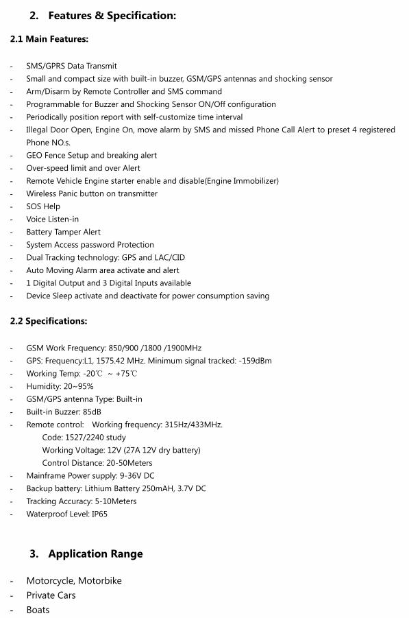
1. How to Insert Simcard
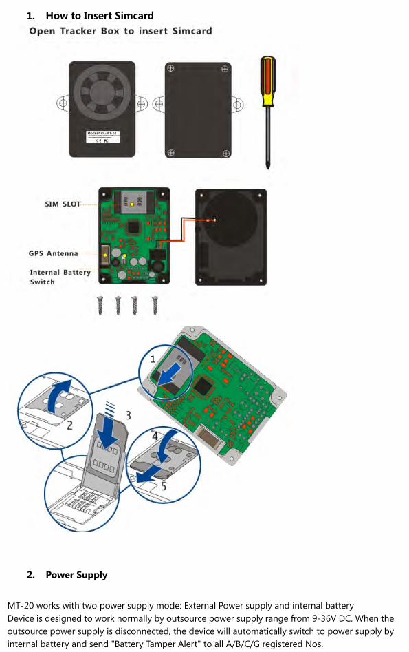
2. Power Supply
MT-20 works with two power supply mode: External Power supply and internal battery Device is designed to work normally by outsource power supply range from 9-36V DC. When the outsource power supply is disconnected, the device will automatically switch to power supply by internal battery and send "Battery Tamper Alert" to all A/B/C/G registered Nos.

Note: Please make sure to switch the internal battery on after you have finished the device configuration and before you seal
the track box back. .
Item Pin No. Wire Color Function/Specification Description
Power 1 Black DC Power Ground,0V
2 Red Power positive pole, +9^36V
Digital Output 3 Grey Immobilizer relay control for ignition
Digital Input
4 Yellow Ignition Check, Positive Trigger(9-36V)
5 Orange Negative Trigger (SOS detect)
6 Brown Negative Trigger ( Door Open/Close Detect)
Microphone 7 Green Mic+
8 Blue Mic-
Installation Position Note: 1) Because the device using built-in GSM/GPS antennas, you have to install the mainframe in the place
which has no metal cover over the unit. Otherwise it will affect the device to receive GPS signal from satellite
2) GPS Antenna Position:
Mount Bracket
Built-in buzzer
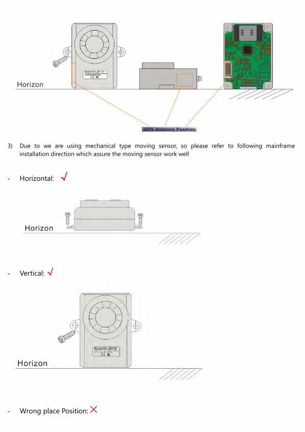
3) Due to we are using mechanical type moving sensor, so please refer to following mainframe
installation direction which assure the moving sensor work well
- Horizontal: √
- Vertical:√
- Wrong place Position:×

3. Transmitter Usage
3.1 Transmitter Operation:
Arm: Buzzer sound once, Armed with Valid GPS signal. Buzzer sound three times, Armed with No valid GPS Signal.
Disarm: Sound Twice, Disarmed successfully. Mute Key: In siren sounding, press this button to stop the sounding. In panic, Activate Siren to sound. Or in parking lot, press this button for car finding.
3.2 Code Program Transmitter to device
MT-20 maximum allow programming 3 Transmitter to control the device. The program method is as follows: 1- Power on device and in standby mode, 2- Press once the SOS button 3- Switch ACC from Off to ON position for 7 times, and the final time is on ACC ON position. The ACC Off
to ON switching time length is about 1-2 second. 4- Siren will sound once and get into code learning mode 5- Press any button of the transmitter, the siren will sound once and it means transmitter code program
successfully. 6- If failed, try again the above process.
Disarm
Arm
Mute
Panic (Siren)
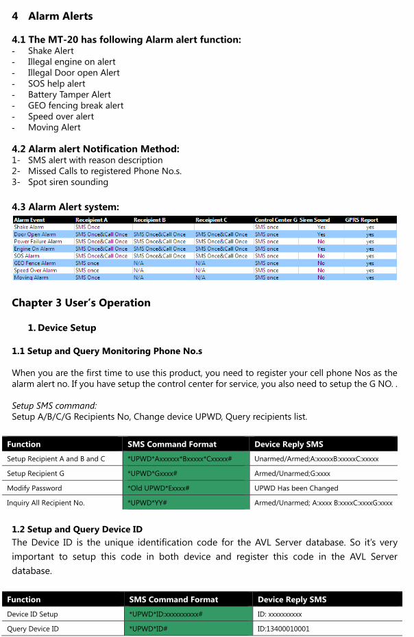
4 Alarm Alerts
4.1 The MT-20 has following Alarm alert function: - Shake Alert - Illegal engine on alert - Illegal Door open Alert - SOS help alert - Battery Tamper Alert - GEO fencing break alert - Speed over alert - Moving Alert
4.2 Alarm alert Notification Method: 1- SMS alert with reason description 2- Missed Calls to registered Phone No.s. 3- Spot siren sounding 4.3 Alarm Alert system:
Chapter 3 User’s Operation
1. Device Setup
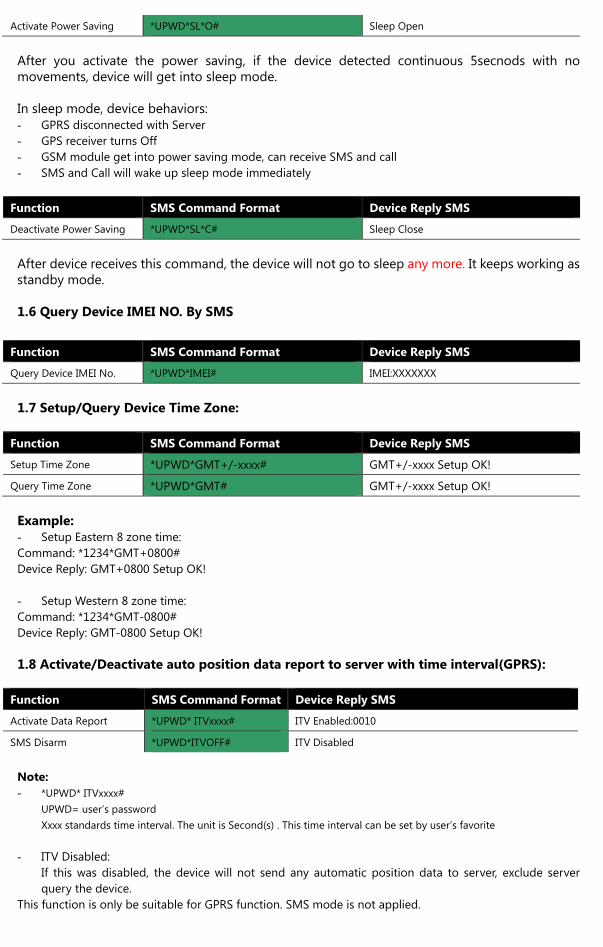
1.1 Setup and Query Monitoring Phone No.s When you are the first time to use this product, you need to register your cell phone Nos as the alarm alert no. If you have setup the control center for service, you also need to setup the G NO. . Setup SMS command: Setup A/B/C/G Recipients No, Change device UPWD, Query recipients list.
Function SMS Command Format Device Reply SMS
Setup Recipient A and B and C *UPWD*Axxxxxx*Bxxxxx*Cxxxxx# Unarmed/Armed;A:xxxxxB:xxxxxC:xxxxx
Setup Recipient G *UPWD*Gxxxx# Armed/Unarmed;G:xxxx
Modify Password *Old UPWD*Exxxx# UPWD Has been Changed
Inquiry All Recipient No. *UPWD*YY# Armed/Unarmed; A:xxxx B:xxxxC:xxxxG:xxxx
1.2 Setup and Query Device ID The Device ID is the unique identification code for the AVL Server database. So it’s very important to setup this code in both device and register this code in the AVL Server database.
Function SMS Command Format Device Reply SMS
Device ID Setup *UPWD*ID:xxxxxxxxxx# ID: xxxxxxxxxx
Query Device ID *UPWD*ID# ID:13400010001

Note:
Xxxxx stands for the device ID code. The device ID only could be number string. Cannot be combination with special icon
or letters of an alphabet;
If you are using this device to work alone without tracking server, then you can leave this setup without setting. 1.3 Setup/Query TCP/IP parameters
Function SMS Command Format Device Reply SMS
Setup IP/Port *UPWD* IP:211.154.142.150*9070# IP:211.154.142.150#9070
Setup APN *1234* APN:CMNET*username*password# APN: CMNET**
Query Parameter *UPWD*QP# IP:211.154.142.155;Port:9001;Device ID:13400010001;
APN:CMNET;Username:China;Password:123456
APN with user name and password setup example: Setup command: *1234*APN:internet.movistar.com.co*movistar*movistar# Device reply: APN:internet.movistar.com.co*movistar*movistar Note: - Only after APN, IP and Port NO. are setup, then the device will begin to dial for GPRS service - If you don’t need device to work in GPRS, please delete all IP ,port and APN - Delete Command:
IP/Port: *UPWD*IP:*# APN: *UPWD*APN:**#
1.4 Setup Device Shocking Sensor sensitivity User can use SMS command to adjust the shocking sensor sensitivity according to individuals’ favorites.
Function SMS Command Format Device Reply SMS
Adjust Shocking Sensitivity *UPWD*VS*xxxx# Vibration Sensitivity xxxx
Note: - XXXX ranges from 0001^9999, the value is bigger, the sensitivity is less. - Recommend Value: Xxxx=0001, means very sensitive Xxxx=5000, Medium level Xxxx=9999, very hard to activate 1.5 Activate/Deactivate Power saving mode: MT-20 has an intelligent power saving design included which considers motorcycle or electricity bicycle has small battery capacity. And to protect the alarm tracker will use out the battery of motor/bikes during their non-use period. In normal working status, the tracker power consumption is normally 70mA. In Standby Mode, power consumption is about 50mA. In power saving mode, power consumption could be less than 20mA. You can use SMS command to setup activate power saving or deactivate power saving:
Function SMS Command Format Device Reply SMS
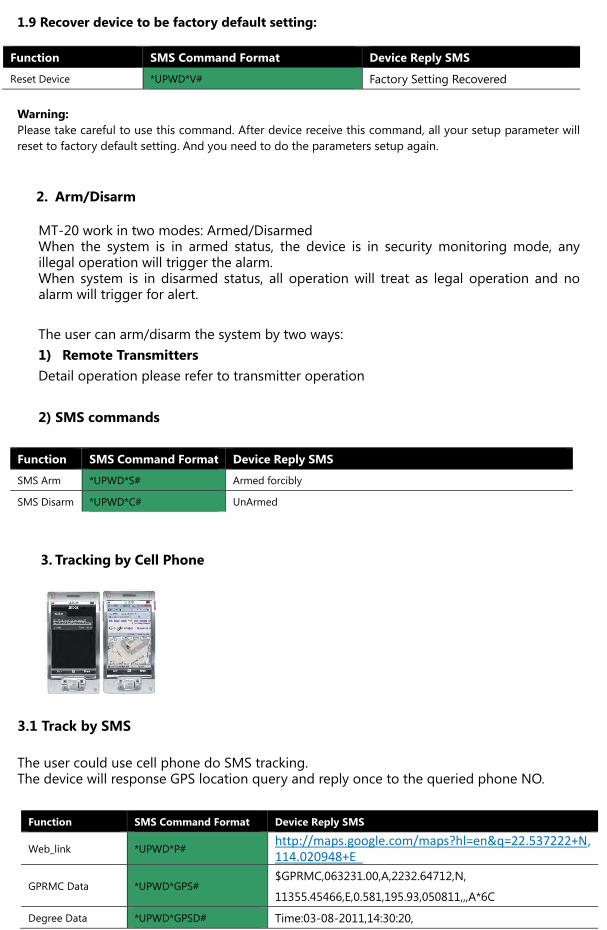
Activate Power Saving *UPWD*SL*O# Sleep Open
After you activate the power saving, if the device detected continuous 5secnods with no movements, device will get into sleep mode. In sleep mode, device behaviors: - GPRS disconnected with Server - GPS receiver turns Off - GSM module get into power saving mode, can receive SMS and call - SMS and Call will wake up sleep mode immediately
Function SMS Command Format Device Reply SMS
Deactivate Power Saving *UPWD*SL*C# Sleep Close
After device receives this command, the device will not go to sleep any more. It keeps working as standby mode. 1.6 Query Device IMEI NO. By SMS
Function SMS Command Format Device Reply SMS
Query Device IMEI No. *UPWD*IMEI# IMEI:XXXXXXX
1.7 Setup/Query Device Time Zone:
Function SMS Command Format Device Reply SMS
Setup Time Zone *UPWD*GMT+/-xxxx# GMT+/-xxxx Setup OK!
Query Time Zone *UPWD*GMT# GMT+/-xxxx Setup OK! Example: - Setup Eastern 8 zone time: Command: *1234*GMT+0800# Device Reply: GMT+0800 Setup OK! - Setup Western 8 zone time: Command: *1234*GMT-0800# Device Reply: GMT-0800 Setup OK! 1.8 Activate/Deactivate auto position data report to server with time interval(GPRS):
Function SMS Command Format Device Reply SMS
Activate Data Report *UPWD* ITVxxxx# ITV Enabled:0010
SMS Disarm *UPWD*ITVOFF# ITV Disabled Note: - *UPWD* ITVxxxx#
UPWD= user’s password Xxxx standards time interval. The unit is Second(s) . This time interval can be set by user’s favorite
- ITV Disabled: If this was disabled, the device will not send any automatic position data to server, exclude server query the device.
This function is only be suitable for GPRS function. SMS mode is not applied.
1.9 Recover device to be factory default setting:
Function SMS Command Format Device Reply SMS
Reset Device *UPWD*V# Factory Setting Recovered Warning: Please take careful to use this command. After device receive this command, all your setup parameter will reset to factory default setting. And you need to do the parameters setup again.
2. Arm/Disarm
MT-20 work in two modes: Armed/Disarmed When the system is in armed status, the device is in security monitoring mode, any illegal operation will trigger the alarm. When system is in disarmed status, all operation will treat as legal operation and no alarm will trigger for alert. The user can arm/disarm the system by two ways: 1) Remote Transmitters Detail operation please refer to transmitter operation 2) SMS commands
Function SMS Command Format Device Reply SMS
SMS Arm *UPWD*S# Armed forcibly
SMS Disarm *UPWD*C# UnArmed
3. Tracking by Cell Phone
3.1 Track by SMS The user could use cell phone do SMS tracking. The device will response GPS location query and reply once to the queried phone NO.
Function SMS Command Format Device Reply SMS
Web_link *UPWD*P# http://maps.google.com/maps?hl=en&q=22.537222+N,114.020948+E
GPRMC Data *UPWD*GPS# $GPRMC,063231.00,A,2232.64712,N,
11355.45466,E,0.581,195.93,050811,,,A*6C
Degree Data *UPWD*GPSD# Time:03-08-2011,14:30:20,
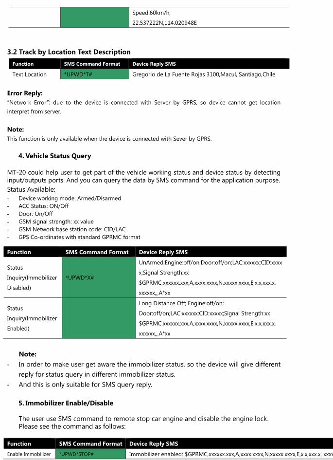
3.2 Track by Location Text Description
Error Reply: “Network Error”: due to the device is connected with Server by GPRS, so device cannot get location interpret from server. Note: This function is only available when the device is connected with Sever by GPRS.
4. Vehicle Status Query
MT-20 could help user to get part of the vehicle working status and device status by detecting input/outputs ports. And you can query the data by SMS command for the application purpose. Status Available: - Device working mode: Armed/Disarmed - ACC Status: ON/Off - Door: On/Off - GSM signal strength: xx value - GSM Network base station code: CID/LAC - GPS Co-ordinates with standard GPRMC format
Note:
- In order to make user get aware the immobilizer status, so the device will give different reply for status query in different immobilizer status.
- And this is only suitable for SMS query reply. 5. Immobilizer Enable/Disable The user use SMS command to remote stop car engine and disable the engine lock. Please see the command as follows:
Function SMS Command Format Device Reply SMS
Enable Immobilizer *UPWD*STOP# Immobilizer enabled; $GPRMC,xxxxxx.xxx,A,xxxx.xxxx,N,xxxxx.xxxx,E,x.x,xxx.x, xxxx
Speed:60km/h,
22.537222N,114.020948E
Function SMS Command Format Device Reply SMS
Text Location *UPWD*T# Gregorio de La Fuente Rojas 3100,Macul, Santiago,Chile
Function SMS Command Format Device Reply SMS
Status
Inquiry(Immobilizer
Disabled)
*UPWD*X#
UnArmed;Engine:off/on;Door:off/on;LAC:xxxxxx;CID:xxxx
x;Signal Strength:xx
$GPRMC,xxxxxx.xxx,A,xxxx.xxxx,N,xxxxx.xxxx,E,x.x,xxx.x,
xxxxxx,,,A*xx
Status
Inquiry(Immobilizer
Enabled)
Long Distance Off; Engine:off/on;
Door:off/on;LAC:xxxxxx;CID:xxxxx;Signal Strength:xx
$GPRMC,xxxxxx.xxx,A,xxxx.xxxx,N,xxxxx.xxxx,E,x.x,xxx.x,
xxxxxx,,,A*xx
Disable Immobilizer *UPWD*K# Immobilizer disabled;
$GPRMC,xxxxxx.xxx,A,xxxx.xxxx,N,xxxxx.xxxx,E,x.x,xxx.x, xxxxxx,,,A*xx
Note: If the immobilizer function has been enabled already, and the user keep sending the same command, the device will reply user by SMS as: Long distance Off; $GPRMC,xxxxxx.xxx,A,xxxx.xxxx,N,xxxxx.xxxx,E,x.x,xxx.x, xxxxxx,,,A*xx
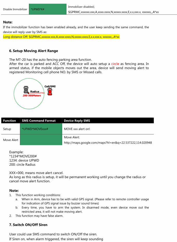
6. Setup Moving Alert Range
The MT-20 has the auto fencing parking area function. After the car is parked and ACC Off, the device will auto setup a circle as fencing area. In armed status, if the mobile objects moves out the area, device will send moving alert to registered Monitoring cell phone NO. by SMS or Missed calls.
Function SMS Command Format Device Reply SMS
Setup *UPWD*MOVExxx# MOVE xxx alert on!
Move Alert Move Alert:
http://maps.google.com/maps?hl=en&q=22.537222,114.020948
Example: *1234*MOVE200# 1234: device UPWD 200: circle Radius XXX=000, means move alert cancel. As long as this radius is setup, it will be permanent working until you change the radius or cancel move alert function. Note: 1. This function working conditions:
a. When in Arm, device has to be with valid GPS signal. (Please refer to remote controller usage for indication of GPS signal issue by buzzer sound times)
b. Every time, you have to arm the system. In disarmed mode, even device move out the restricted area, it will not make moving alert.
2. This function may have false alarm.
7. Switch ON/Off Siren
User could use SMS command to switch ON/Off the siren. If Siren on, when alarm triggered, the siren will keep sounding
If Siren Off, when alarm triggered, the siren will not sound
Function SMS Command Format Device Reply SMS
Switch On Siren *UPWD*SIRENON# SIRENON OK
Switch Off Siren *UPWD*SIRENOFF# SIRENOFF OK
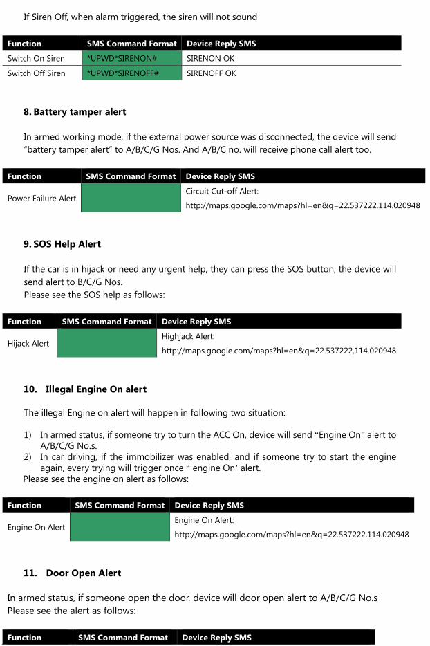
8. Battery tamper alert
In armed working mode, if the external power source was disconnected, the device will send “battery tamper alert” to A/B/C/G Nos. And A/B/C no. will receive phone call alert too.
Function SMS Command Format Device Reply SMS
Power Failure Alert Circuit Cut-off Alert:
http://maps.google.com/maps?hl=en&q=22.537222,114.020948
9. SOS Help Alert
If the car is in hijack or need any urgent help, they can press the SOS button, the device will send alert to B/C/G Nos. Please see the SOS help as follows:
Function SMS Command Format Device Reply SMS
Hijack Alert Highjack Alert:
http://maps.google.com/maps?hl=en&q=22.537222,114.020948
10. Illegal Engine On alert
The illegal Engine on alert will happen in following two situation: 1) In armed status, if someone try to turn the ACC On, device will send “Engine On” alert to
A/B/C/G No.s. 2) In car driving, if the immobilizer was enabled, and if someone try to start the engine
again, every trying will trigger once “ engine On’ alert. Please see the engine on alert as follows:
Function SMS Command Format Device Reply SMS
Engine On Alert Engine On Alert:
http://maps.google.com/maps?hl=en&q=22.537222,114.020948
11. Door Open Alert
In armed status, if someone open the door, device will door open alert to A/B/C/G No.s Please see the alert as follows:
Function SMS Command Format Device Reply SMS
Door Open Alert
Door Open Alert; :
http://maps.google.com/maps?hl=en&q=22.53722
2,114.020948
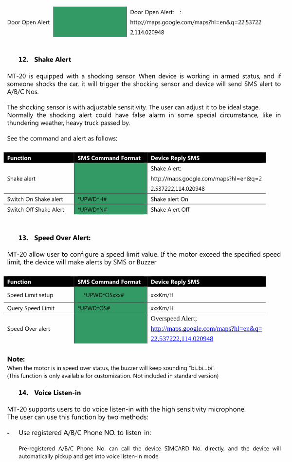
12. Shake Alert
MT-20 is equipped with a shocking sensor. When device is working in armed status, and if someone shocks the car, it will trigger the shocking sensor and device will send SMS alert to A/B/C Nos. The shocking sensor is with adjustable sensitivity. The user can adjust it to be ideal stage. Normally the shocking alert could have false alarm in some special circumstance, like in thundering weather, heavy truck passed by. See the command and alert as follows:
Function SMS Command Format Device Reply SMS
Shake alert
Shake Alert:
http://maps.google.com/maps?hl=en&q=2
2.537222,114.020948
Switch On Shake alert *UPWD*H# Shake alert On
Switch Off Shake Alert *UPWD*N# Shake Alert Off
13. Speed Over Alert:
MT-20 allow user to configure a speed limit value. If the motor exceed the specified speed limit, the device will make alerts by SMS or Buzzer Function SMS Command Format Device Reply SMS
Speed Limit setup *UPWD*OSxxx# xxxKm/H
Query Speed Limit *UPWD*OS# xxxKm/H
Speed Over alert
Overspeed Alert;
http://maps.google.com/maps?hl=en&q=
22.537222,114.020948
Note: When the motor is in speed over status, the buzzer will keep sounding “bi..bi…bi”. (This function is only available for customization. Not included in standard version)
14. Voice Listen-in
MT-20 supports users to do voice listen-in with the high sensitivity microphone. The user can use this function by two methods: - Use registered A/B/C Phone NO. to listen-in:
Pre-registered A/B/C Phone No. can call the device SIMCARD No. directly, and the device will automatically pickup and get into voice listen-in mode.
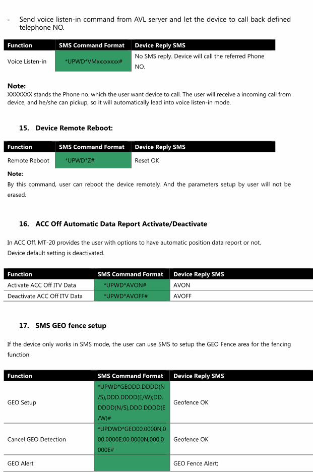
- Send voice listen-in command from AVL server and let the device to call back defined
telephone NO.
Function SMS Command Format Device Reply SMS
Voice Listen-in *UPWD*VMxxxxxxxx# No SMS reply. Device will call the referred Phone
NO.
Note: XXXXXXX stands the Phone no. which the user want device to call. The user will receive a incoming call from device, and he/she can pickup, so it will automatically lead into voice listen-in mode.
15. Device Remote Reboot:
Function SMS Command Format Device Reply SMS
Remote Reboot *UPWD*Z# Reset OK
Note:
By this command, user can reboot the device remotely. And the parameters setup by user will not be
erased.
16. ACC Off Automatic Data Report Activate/Deactivate
In ACC Off, MT-20 provides the user with options to have automatic position data report or not.
Device default setting is deactivated.
Function SMS Command Format Device Reply SMS
Activate ACC Off ITV Data *UPWD*AVON# AVON
Deactivate ACC Off ITV Data *UPWD*AVOFF# AVOFF
17. SMS GEO fence setup
If the device only works in SMS mode, the user can use SMS to setup the GEO Fence area for the fencing
function.
Function SMS Command Format Device Reply SMS
GEO Setup
*UPWD*GEODD.DDDD(N
/S),DDD.DDDD(E/W);DD.
DDDD(N/S),DDD.DDDD(E
/W)#
Geofence OK
Cancel GEO Detection
*UPDWD*GEO00.0000N,0
00.0000E;00.0000N,000.0
000E#
Geofence OK
GEO Alert GEO Fence Alert;
http://maps.google.com/maps?hl=en&q=22.53722
2,114.020948
Note:
- This function is only suitable for those don’t need GPRS function. And they want the device to work in SMS only.
- The coordinates in this setup command need use all data as Degrees. Which means user need to express the coordinates with Degrees format
Chapter 4 Device and Server Air Traffic Protocol Please refer to MT-20 Air Traffic Protocol Document (Sever Part) This is only provided to system integrator or distributors.