Mt hermon. mt carmel mt horeb mt hermon mt gerizim mt hebron.

Pelli
niS.
p.A
.vi
a Fu
sari
, 19
• 26
845
Co
do
gn
o (
LO)
ITA
LIA
T
. + 3
9 03
77 4
6641
1 •
F. +
39
0377
437
635
• in
fo@
pel
lini.n
et
Edit
ion
05.
07
www.pellini.net
visu
al d
esig
n: s
tefa
no
sib
on
i.it
engl
ish
Tech
nic
al C
atal
og
ue
Scre
enLin
e
Gen
eral
sec
tio
n
ScreenLine®
MT copertina parte generale_GB 20-04-2007 12:18 Pagina 1

MT parte generale_GB 15-05-2007 10:04 Pagina 2

Welcome to ScreenLine® 4
Main characteristics of ScreenLine® double-glazed unit with blind 4
Additional characteristics of the ScreenLine® product 6
Feasibility tables 9
1. How to determine the glass thickness 10
2. Glass deflection 11
3. Feasibility check 15
Order form 16
Checks upon receipt 18
Precautions for fitting 19
Final Inspection 23
Transport and storage 24
Installation 25
Warranty 32
Special applications 39
Manufacturer’s Quality Scheme 40
Certifications 41
Spectro-photometric characteristics of an integrated system 43
1. Definitions of the faces of an integrated system 43
2. Spectro-photometric characteristics 44
3. Colour rendition 48
4. Energy balance 52
5. Mechanical stresses of thermal origin 56
6. Thermal bridges 59
ScreenLine®
MT parte generale_GB 15-05-2007 10:04 Pagina 3

ScreenLine
Tech
nic
al C
atal
og
ue
Welcome to ScreenLine®
ScreenLine
Pellini S.p.A. manufactures integral blinds and - under the trademark ScreenLine® - blinds specially
designed for fitting within insulating glass units.
The components, the production standards, the inspection procedures, the equipment and the pro-
duction plant are all designed to meet this requirement.
ScreenLine® blinds use a patented system for transmitting motion, and are located within the unit’s
perimeter spacer bars.
This ensures the integrity of the unit’s hermetic seal, and enables the producer of the insulating unit
to use his own working methods on automated assembly lines.
The magnetic transmission system and the assembly and electrical connection systems are covered by
appropriate international patents owned by Pellini S.p.A.
Main characteristics of ScreenLine® double-glazed unit with blind
Tightness of the system
The ScreenLine® kit is fitted within the double-glazed unit without compromising the unit’s
special characteristics, and without altering the tightness of the joint, which is dependent only
on the sealing material and the technology used by the insulating glass unit manufacturer.
The unit must comply with draft Standard EN 1279/2, which requires the moisture penetration
index (MPI) to be less than 20%. This evaluation is carried out in the laboratory using suitable
aging cycle procedures on sample double-glazed units.
Magnetic transmission
The movement of the blind inside the double-glazed unit, in the magnetic system, is produced by a
pair of magnets interfaced with each other, one located inside and the other outside the double-gla-
zed unit. The absence of contact between the two parts means that the unit can be a sealed system,
resulting in longer life for the internal components, which are not rigidly connected to the external
actuating devices. The magnets used are in Neodymium N35H, permanent, resistant to high tempe-
ratures (up to 120°C), and have a double surface covering in order to improve oxidisation resistance
and stronger attachment to the support holder.
Ease of assembly
ScreenLine® kits are designed to be directly assembled on automatic production lines for double-gla-
zed units, reducing operations and assembly time to a minimum by the use of exclusive (patented)
solutions. The warranty on the finished product (blind kit and double-glazed unit) is valid provided
that the manufacturing procedures suggested in the ScreenLine® Handbook are followed, with
regard to the following points:
• cleaning the glass
• assembling the kit
• sealing
This Handbook also recommends procedures for transport and warehouse storage of double-glazed
units with the kit fitted.
Tig
htn
ess
Mag
net
ic t
ran
smis
sio
n
Ease
of
asse
mb
ly
4
MT parte generale_GB 15-05-2007 10:04 Pagina 4

5ScreenLine
Non fogging components
The components used in the production of ScreenLine® kits for assembly inside double-glazed units
have been specially designed to avoid the release of substances that can jeopardize the transparency
of the glass (fogging effect), within the limits fixed by the EN 1279/6 standard. External Institute have
certified this feature, and Pellini’s own laboratory carries out continuous checking of incoming bat-
ches of materials so that only suitable components are used in production.
Lifetime
Life tests are performed in the Pellini laboratory to establish the minimum number of cycles to be excee-
ded without faults occurring in the kits.
The suitability of ScreenLine® kits for use inside insulating glass units has been verified by external insti-
tutes and laboratories, by subjecting the various kits to cycles at high temperatures, to demonstrate that
their lifetime exceeds the warranty that is normally given on an insulating glass unit. In all the tests, on
kits with the largest feasible surface area, the kits exceeded 20.000 cycles of raising and lowering.
The components of the internal magnetic assembly (worm gear and pinion) are C.N.C. machined and
surface-hardened.
The reducer for the internal motor is entirely made of steel. The gears are toothed, the external sproc-
ket is broached, and the planetary supports have guide rollers fitted. On the outlet side there are two
bearings.
The electronic card for the internal motor has survived the severe durability test imposed by the German
certifying authority TÜV, using the thermal and mechanical shock tests specified by standards DIN EN
60068-2-14 and DIN EN 60068-2-29.
All blinds produced with the ScreenLine® trademark are guaranteed to operate for five years.
No
n f
og
gin
g
Life
tim
e
MT parte generale_GB 15-05-2007 10:04 Pagina 5

Additional characteristics of ScreenLine® products
The ScreenLine® kit, when fitted inside the perimeter spacer bars, without altering its characteristics,
confers a number of indisputable advantages, such as:
• long-term protection against atmospheric agents, dust and dirt
• long-term protection against deformation or damage
• freedom from maintenance
• quality of the blind maintained over time
• resistance of the slats and other components of the blind to UV radiation without yellowing
• integral screening against solar radiation
• effective reduction in thermal transmission values
• possibility of completing the finished product in the factory (double-glazed unit with built-in blind)
at relatively low cost and with guaranteed quality.
Other characteristics are connected with the method of producing the blinds and the components
used. It is worth remembering some of the most important characteristics.
Forming the slats
The slats are manufactured with special care, as their appearance is an important quality for confer-
ring elegance and prestige on the product. For this reason the production cycle now includes pro-
cessing systems with computerized control machines for the cambering and finishing of the slats.
Aluminium head and bottom rails
Another feature which distinguishes the ScreenLine® range in terms of quality is the use of extruded
painted aluminium for making both the head rail and the bottom rail. This sets it apart from products
made of sheet metal.
Smooth bottom rail
An important feature is the absence of projecting details or end-caps on the bottom rail, which has
a perfectly smooth surface. In terms of appearance this means a perfectly clean line, and in practical
terms it excludes the possibility of components of the blind coming loose and being deposited on the
bottom inside surface of the double-glazed unit.
Extruded spacer bars
All the spacer bars used in ScreenLine® kits are made of extruded aluminium, ensuring quality and
robustness. This enables the use of geometrical configurations which best fit the aesthetic and func-
tional requirements.
Trademark
A raised trademark distinguishing the product with the ScreenLine® logo is applied on the bottom
rail, assuring product originality.
Mono-control
The raising and tilting functions are both controlled by means of one cord. This formal synthesis ena-
bles the blind to be operated without compromising simplicity of appearance.
ScreenLine6
Form
ing
Mo
no
-co
ntr
ol
Tech
nic
al C
atal
og
ue
MT parte generale_GB 15-05-2007 10:04 Pagina 6

Removable control
The new external cord-operated magnetic control, which is compact in height, features a system for
easy removal from the glass, enabling thorough cleaning. It also means safety where children are
concerned, as it will come away from the unit if overloaded.
Sliding control
Operating the pleated blind with a control which slides on the glass and can be removed when neces-
sary, makes the system extremely fast, easy to understand, and free to operate in all four directions,
including operating at any angle of inclination.
Control from below
To facilitate moving the slats in windowsill applications, ScreenLine® offers the solution with control
from below by means of a removable knob. Movement is transmitted to the top of the blind by two
internal gears and a transmission completely contained in the side spacer bar, without reducing the
internal visible width.
Cord tensioner
An improvement in the product line has been achieved with the introduction of the cord tensioner
which allows the cord to be fixed in a perfectly vertical position, ensuring that it runs in a straight
line.
Versatility
It is a quick and easy operation to switch from external manual control to external motorized control
by simply switching components, without the need for fundamental modifications to the system.
This gives it the special feature of great versatility.
Removable wand
ScreenLine® takes account of special cases where it is preferable to have a system without a visible
external drive so as not to interrupt the continuity of the glass.
It is recommended for use where it is desirable to restrict access to the controls to authorised peo-
ple: in hospitals (for hygiene reasons), schools (in the interests of order and safety), restaurants, con-
servatories, swimming pools and public places in general.
ScreenLine® has designed a removable wand for these situations, which allows the blind to be adju-
sted and then the wand removed.
Control knob
The control knob, in the flush system, offers the same function without the possibility of access, but
is limited to the tilting movement.
Total compactness
In the roller version, the ScreenLine® kit is completely contained within the dimensions of the frame
of spacer bars and the special upper pelmet which blocks the passage of direct light.
7ScreenLine
Slid
ing
co
ntr
ol
Ver
sati
lity
Wan
d
Co
mp
actn
ess
Co
ntr
ol f
rom
bel
ow
MT parte generale_GB 15-05-2007 10:04 Pagina 7

Only two wires
The operation of the ScreenLine® motorised system requires only two wires for power supply and
control of the blinds, simplifying the electrical work and minimising the space necessary for the
power supply line.
The external motor uses a channelled wave system which means that up to 16 blinds can be con-
nected and controlled, singly or in groups, with a single pair of wires connecting the blinds to each
other and to the control unit.
Synchronisation and quality
The motorised system uses a double encoder which among other things enables synchronised ope-
ration of several blinds connected together, so as to guarantee perfect alignment when tilting and
moving the blinds.
The reduction gear is entirely made of high-strength steel, and the electronic components are desi-
gned for industrial temperature ranges.
Colour range and combinations
The available colour range of the slats and pleated fabrics is wide and carefully based on a num-
ber of elegant and sophisticated shades.
The external control mechanism is supplied in transparent as standard, in combination with all
colours of slats; and in transparent in combination with all colours of fabric.
The external control mechanism is also produced in white, light grey and dark grey colourways.
Any desired colour combination can be supplied on request.
ScreenLine8
On
ly t
wo
wir
esSy
nch
ron
isat
ion
an
d q
ual
oty
Co
lou
r ra
ng
e
MT parte generale_GB 15-05-2007 10:04 Pagina 8

Feasibility tables
The feasibility of a blind within a double-glazed unit using the magnetic
system is dependent on the thickness of the inner sheet of glass and its
dimensions. Depending on these parameters, the feasibility table gives the
measurements of blinds that can be made and will function correctly.
Before proceeding to order a double-glazed unit with blind, using the magne-
tic system, it is important to do a feasibility check, i.e. to assess whether it is
possible to make it in the size required.
The tables have been calculated for each model and for various thicknesses of
glass interposed between the magnets (inner sheet of glass), taking account
of the weight and frictional resistance of the blind, and dividing the maximum
torque transmitted (before slippage between the magnets) by an appropriate
safety factor. In manual systems, the thickness of the glass is crucial, because
the torque transmitting the movement to the mechanisms inside the head rail
depends on the thickness of the glass. By way of example, the curve in the
graph below refers to the control on model SL27C.
For models with internal motor, the tables define the surface area realisable,
depending on the motor torque (calculated with an appropriate safety factor).
The feasibility tables, which are shown in the price list and in the handbook,
must be consulted before ordering.
The tables have been calculated assuming conditions of free movement of the
blind inside the double-glazed unit. No allowance has been made for friction
between blind and glass as a result of any deflection in the glass.
With regard to this, please refer to the chapter on glass deflection.
9ScreenLine
0
0,2
0,4
0,6
0,8
1,2
1,4
4 6 8 10 12
1,0
Magnetic torque
glass thickness
torq
ue
valu
e in
Ncm
Feas
ibili
ty t
able
s
MT parte generale_GB 15-05-2007 10:04 Pagina 9

1. How to determine the glass thickness
The glass thickness is obtained by taking into account the sum total of the thicknesses.
For this, please bear in mind the composition of the glass:
MONOLITHIC
thickness (mm) 4 - 5 - 6 - 8 - 10 - 12
LAMINATED
composed of one or more sheets of polyvinylbutyl (PVB plastic) between two sheets of glass, which
determine the strength and thickness of the PVB, in accordance with the following classification:
0,38 mm (referred to as 1)
0,76 mm (referred to as 2)
1,52 mm (referred to as 4)
The glass type is conventionally defined by a three-figure number (e.g. 55.4). The first two figures
indicate the thickness of the sheets of glass, and the third indicates the thickness of the PVB (see clas-
sification above). The calculation of the total thickness is made by adding the thickness of the sheets
of glass to that of the PVB and rounding up to the next higher unit.
ScreenLine10
Tech
nic
al C
atal
og
ue
Glass with PVBLAMINATED
Plain glass MONOLITHIC
MT parte generale_GB 15-05-2007 10:04 Pagina 10

11ScreenLine
2. Glass deflection
Variations in temperature and pressure between the assembly site and the
installation site can create deflection in sheets of glass which can obstruct
the operation of integral blinds. This deflection is greater in the case of
systems with a wider cavity between the sheets of glass, and also in the case
of relatively thin sheets of glass.
It is therefore advisable to bear these parameters in mind at the design stage,
and to carry out equalisation of the air cavities in the units, conditioning
them at lower temperatures if assembly is being carried out in the hotter
months, and as far as possible avoiding extreme temperature differences
between the assembly site and the operating conditions of the integral
system. This equalisation should also take account of the possible difference
in atmospheric pressure. In the event that the assembly of the integral dou-
ble-glazed unit takes place in summer, with high levels of humidity in the air,
at a distance of several hours from the assembly site, the dehydrating effect
of the molecular sieves causes a further reduction in the width of the cavity,
thus contributing to the deflection in the faces of the glass. One method for
limiting the deflection of the glass, thus avoiding integral blinds getting jam-
med, is the use of argon gas.
In this way it is possible to avoid operating problems in the systems, as the
gas injected into the cavity in the double-glazed unit, by expanding, causes
cooling of the cavity itself, and at the same time eliminates the humidity in
the air which is present at the time of assembly.
2.1 European environmental reference data (Directive IFT 8/05)
The possible environmental conditions in which the finished system is used,
refer to the literature in certain directives and regulations in the European
sphere, such as the IFT Directive (August 2005 - Annexe B).
Production data
Maximum temperature at the production site 27 °C
Minimum pressure at the production site 990hPa
Installation site data
External ambient temperature -10 °C
Internal ambient temperature 19 °C
Temperature of cavity 2 °C
Atmospheric pressure of the installation environment 1030hPa.
Variation in altitude between production site and installation site -300 m
Variation in temperature between production site and installation site -25 °C
MT parte generale_GB 15-05-2007 10:04 Pagina 11

By way of example, Table 1 illustrates the results of the calculation of the deflection of the glass faces
of an integral double-glazed unit with dimensions 1000 mm x 1000 mm, particularly useful if com-
pared with the overall measurements of the integral blind (slats, ladder tape, bottom rail), represen-
ted in Table 2, for the purposes of avoiding malfunctioning in integral systems.
ScreenLine12
Tech
nic
al C
atal
og
ue
Key
C4 float glass thickness 4 mm
C8 float glass thickness 8 mm
F33 laminated 3+3 mm
F44 laminated 4+4 mm
F55 laminated 5+5 mm
Composition of Assembly Installation Assembly Installation Single Resultingdouble-glazed temperature temperature pressure pressure deflection cavity between
Temperature glass facesunit outer of cavity
glass cavityinner glass °C °C hPa hPa mm mm
C4 20 C4 18 2 990 1030 2,5 15
F33 20 F33 18 2 990 1030 2,3 15,4
F44 20 F44 18 2 990 1030 2,3 15,4
F55 20 F55 18 2 990 1030 2,2 15,6
C4 27 C4 18 2 990 1030 3,0 21,0
F33 27 F33 18 2 990 1030 2,9 21,2
F44 27 F44 18 2 990 1030 2,9 21,2
F55 27 F55 18 2 990 1030 2,9 21,2
C4 20 C4 27 2 990 1030 3,0 14,0
F33 20 F33 27 2 990 1030 3,0 14,0
F44 20 F44 27 2 990 1030 3,0 14,0
F55 20 F55 27 2 990 1030 3,0 14,0
C4 27 C4 27 2 990 1030 3,8 19,4
F33 27 F33 27 2 990 1030 3,8 19,4
F44 27 F44 27 2 990 1030 3,8 19,4
F55 27 F55 27 2 990 1030 3,8 19,4
C8 20 C8 18 2 990 1030 2,1 15,8
C8 27 C8 18 2 990 1030 2,7 21,6
C8 20 C8 27 2 990 1030 2,8 14,4
C8 27 C8 27 2 990 1030 3,6 19,8
MT parte generale_GB 15-05-2007 10:04 Pagina 12

13ScreenLine
Values for deflection depend on the dimensions of the unit and particularly on the ratio between the
lengths of the sides. Units where the ratio (longer side divided by shorter side) is very large have less
deflection than those with a smaller ratio. The use of laminated glass does not limit the amount of
deflection, which is the same as would result from the use of monolithic glass of the same thickness.
Model Slat/ Ladder tape Bottom rail Total Internal Difference Maximum Pleated (both sides) width cavity (unit-blind) deflection allowed
SL20C 12,5 3 14 15,5 20 4,5 2,25
SL20C Plissé 14 15 15 20 5 2,5
SL20CB 12,5 3 14 15,5 20 4,5 2,25
SL20M 12,5 3 14 15,5 20 4,5 2,25
SL20M Plissé 14 14 14 20 6 3
SL20P 12,5 2 14 14,5 20 5,5 2,75
SL20S 14 14 14 20 6 3
SL22C 12,5 3 14 15,5 22 6,5 3,25
SL22C Plissé 14 15 15 22 7 3,5
SL22M 12,5 3 14 15,5 22 6,5 3,25
SL22M Plissé 14 14 14 22 8 4
SL22S 14 14 14 22 8 4
SL24P 16 2 14 18 24 6 3
SL27C 16 3 14 19 27 8 4
SL27C Duette 20 20 20 27 7 3,5
SL27C Plissé 20 20 20 27 7 3,5
SL27C Rullo 7 7 27 20 5 (external) 15 (internal)
SL27M 16 3 14 19 27 8 4
SL27M Duette 20 20 20 27 7 3,5
SL27M Plissé 20 20 20 27 7 3,5
SL27M Rullo 7 7 27 20 5 (external) 15 (internal)
SL32C 16 3 14 19 32 13 6,5
SL32C Duette 25 20 25 32 7 3,5
MT parte generale_GB 15-05-2007 10:04 Pagina 13

2.2 Equalising the double-glazed unit
If the fabrication site and the transport and installation sites are at different heights, this can give rise
to significant deflection in the double-glazed unit, sufficient to cause damage to the integral blind.
If the size of the air cavity has been reduced to the point where the operation of the venetian blind
is compromised, it is advisable to equalise the pressure in the cavity without packing (fully raising) or
lowering the blinds, to avoid the internal raising cords breaking or becoming tangled.
Equalisation must be carried out using the same procedures as for a standard double-glazed unit, in
accordance with EN 1279-2 regulations concerning the vapour seal of the perimeter joint.
For this process, please follow the instructions given in this handbook and the recommendations on
sealing and the atmosphere inside the cavity. The diagram below represents the reduction in the size
of the cavity in a double-glazed unit as a result of the environmental conditions described, as a pro-
portion of the size of the cavity itself. The integral system referred to in this instance is an insulating
glass unit with measurements 1000 mm x 1000 mm and a glass thickness of 4 mm.
ScreenLine14
Tech
nic
al C
atal
og
ue
0
2
4
6
8
10
12
0 10 20 30 40
assemblyp=990hPa t=27°C
assemblyp=990hPa t=18°C
installationp=1030hPa t=2°C
Deflection in the double-glazed unit
cavity in (mm)
def
lect
ion
in (
mm
)
MT parte generale_GB 15-05-2007 10:04 Pagina 14

15ScreenLine
30
40
50
60
70
80
90
100
110
120
130
140
150
160
170
180
190
200
210
220
230
240
250
30 35 40 48 58 70 80 90 100 110 120 130 140 150 160 170 180 190 200 210 220 230 240 250 260 270 280 290 300
260
270
280
290
300
Width cm
Hei
ght
cm
WH
3
1
2
Table for Model SL27C with glass thickness 6 mm
Dimensions required 1700 mm x 1400 mm (L x H)
Feasible (with reduced system R)
Dimensions required 2200 mm x 2500 mm (L x H)
Not feasible with raising
Note. These dimensions can be implemented if tilting is the only function required; the blind is sup-
plied packed (fully raised) and must be lowered only after installation of the unit in the frame.
Dimensions required 400 mm x 2000 mm (L x H)
Feasible with tilting only, with bottom rail locked or raisable with double head rail system
1
2
3
Raisable and tiltable by the
Direct system
Raisable and tiltable by the
Reduced system
Tiltable only, with blind supplied
packed (fully raised)
Tiltable only, with bottom rail
locked or raisable with double
head rail system
3. Feasibility check
To find out if a manual ScreenLine® kit can be made, check the feasibility in the tables for the desi-
red models, according to the dimensions of the double-glazed unit and the thickness of the inner
sheet of glass.
In the case of laminated glass, look up the next whole millimetre size above the thickness of the inner
sheet of glass. As an example of how to read the tables, let us take Model SL27C with inner glass
thickness of 6 mm:
MT parte generale_GB 15-05-2007 10:04 Pagina 15

Order form
Purchase of the ScreenLine® kit is governed by an order form specially created for each system, which
you will find at the end of each brochure in the ScreenLine® 2006 Technical Handbook / Price List
devoted to the specific system which you intend to purchase.
Please fill in all parts of this form correctly, as indicated below.
Instructions for filling in the ScreenLine® order form
1. Customer
Space for indicating business name, address, VAT reg. no., telephone, fax and email address of the
person submitting the order.
2. Ref.
Customer’s internal reference.
3. Q.ty
Specify the quantity required.
4. Models
Check the model of double-glazed unit required.
Specify whether a special kit is required (profiled, inclined etc.), and whether the external motor is
required, by checking the appropriate boxes in the last columns.
5. Glass
Specify width, height and thickness of the glass from the control side (inside) in millimetres.
Specifying the glass thickness is essential for verifying the feasibility of the double-glazed unit.
ScreenLine16
Ord
er f
orm
ScreenLine® Division of Pellini S.p.A.via Fusari, 19 • 26845 Codogno • ItaliaT. + 39 0377 466411 • F. + 39 0377 437635 / 436001
Customer
Righ
t
Left
date signature
Q.ty Models Control SlatRef.
Cordlength
mm
Fabric Notes
Width
mm mm
Glass
Height Thickness
mm
controlslide
Type ColourColour
Exte
rnal
mot
or
*Depth of theperimeter seal
(excluding spacer bar)
ScreenLine® System C
SL22
C P
lissé
SL22
C
SL27
C P
lissé
SL20
C
SL20
C P
lissé
mmSL27
C
SL27
C R
ullo
SL32
C D
uett
e
SL32
C
SL32
C P
lissé
standard control
optional
transparent
white light grey anthracite
1
2 3 4 5 6 7 8 9 10
ScreenLine®
MT parte generale_GB 15-05-2007 10:04 Pagina 16

17ScreenLine
6. Depth of perimeter seal
Complete this column only if the depth of seal required is different from the depth quoted as stan-
dard at the bottom of the order form. It is important to check that there is sufficient space around
the magnet to house the control assembly. This is necessary in order for the system to function cor-
rectly. For this to happen, the line of the glazing bead must not cover the inner edge of the spacer
bar.
7. Control
Specify the desired location for the control assembly - seen from the interior - (left or right). In the
case of cord systems, the cord is supplied 65 mm shorter than the height of the glass. Specify the
cord length required only if you want a different length.
Note. ‘Cord length’ here means the cord loop height.
For knob operated systems (SL20, SL24P), the cable length (L) is supplied as shown in the table in
the price list.
Specify the cable length required only if you want a different length.
8. Slats
Specify the slat colour required, using the numbers quoted in the catalogue or price list.
9. Fabric
Specify the fabric colour required, according to the numbers quoted in the catalogue or price list.
Please also specify the quality required. Four different qualities of fabric transparency are available:
816 transparent
812 semi-transparent
878 opaque
Note. The external surface is always metallic / aluminium finish. The inside surface is coloured.
10. Note
Space reserved for specifications or requests.
Standard control
The standard colour for the magnetic control and the cord tensioner is transparent.
Cord loop: light grey.
Available on request: white, light grey, anthracite.
Standard specifications
The second seal, mentioned in the note at the bottom of the order form for each model, is normally
treated as 4 mm for 27 and 32 mm cavities, while for 20 and 22 mm cavities a seal 5,5 mm deep is
specified. If you are using a different thickness of seal, please specify it in the appropriate column on
the order form. The dimensions of the blind are actually calculated from the difference between the
dimensions of the glass and the dimensions of the spacer bar and seal.
These details are processed by the production office for determining the nominal measurements of
the glass which is stated on the adhesive label accompanying the ScreenLine® kit.
MT parte generale_GB 15-05-2007 10:04 Pagina 17

ScreenLine18
Ch
ecks
up
on
rec
eip
t
Checks upon receipt
Check the integrity of the packaging
Immediately on receipt of the ScreenLine® kit, check that the packaging is in good condition.
Check that the order details correspond to those on the transport document.
Whatever the condition, always add the comment “subject to inspection” on the transport docu-
ment issued by the carrier.
Only if this is done, can any goods damaged in transport be replaced under warranty, by virtue of
the insurance cover on the blind.
On opening the package, check that contains all the component parts for the particular model, as
specified in the catalogue or price list. Only open the individual component packs at the time of using
the product.
Each package is identified with a label indicating:
1. order number
2. model of blind
3. customer
4. colour
5. dimensions
Tenda Veneziana ScreenLine SL20C New S157 larg. 573 x alt. 837 ComandoDestro H. standard-Diretto-Comando Est. New + Tendicorda Trasparente, conangolari in plastica e canaline ribassate
070001206 2007-OC-0000571-001del 16/01/07 per 02/02/07VETRERIA CRISTALLINA snc
1
23
45
MT parte generale_GB 15-05-2007 10:04 Pagina 18

Precautions for fitting
General rules
In the area for assembling the ScreenLine® kit with the glass, the work surface must be clean and
dust-free.
The pack containing the blind must be opened just before being assembled, in order to avoid possi-
ble contamination or damage.
Handle the blinds and the accessories with the greatest care and cleanliness:
• use cotton gloves
• do not deform the slats or damage the fabric
• avoid the blind and its accessories coming into contact with butyl, oily substances, dust and sol-
vents.
Accidental contamination should not be removed using solvent cleansers, which can damage the
blind and later cause ‘fogging’. Use isopropyl alcohol as necessary.
Washing and rinsing the glass
Carefully wash the sheets of glass so as to eliminate dirt (dust from the packaging for the glass, chalk,
fingerprints etc.) and oily residues from the cutting fluid. For standard float and low-emissivity pyroly-
tics, use of an alkaline detergent is recommended. For cleaning low-emissivity magnetronic glasses,
it is advisable to use a neutral detergent. In all cases, make sure that the sheets of glass are properly
rinsed and perfectly clean. With time, any deposits that may be present, can cause streaks on the
glass, in the vicinity of the ladder tape (due to the friction it causes), creating marks on the inner faces
of the double-glazed unit which are hard to remove. Proper washing and rinsing avoids these defects.
Do not use surface-active detergents, as they are difficult to remove in double-glazed unit washing
systems.
Preparing the spacer bars
Assemble the spacer bars using the following method:
• make the holes for replacing the air with argon gas
• fill the spacer bars with the requisite amount of molecular sieve in accordance with the manufac-
turer’s Quality Scheme.
For this purpose we recommend using a 3 A° molecular sieve in order to selectively capture the
moisture but not the injected gases, thus reducing the possibility of subsequent glass deflection
• apply the butyl correctly to the spacer bars, avoiding any spillage, in accordance with the quanti-
ties laid down by the specifications in the manufacturer’s Quality Plan. Seal the corners with extru-
ded butyl, eliminating gaps and at the same time making sure that the joints between the spacer
bars and the corner keys are sealed, by covering the four corners of the double-glazed unit com-
pletely with butyl.
Assembling the components
For instructions on positioning the spacer bars and the blind on the glass, please refer to the assembly
diagrams and the descriptions relating to the model in question.
19ScreenLine
Prec
auti
on
s fo
r fi
ttin
g
MT parte generale_GB 15-05-2007 10:04 Pagina 19
ScreenLine20
Tech
nic
al C
atal
og
ue
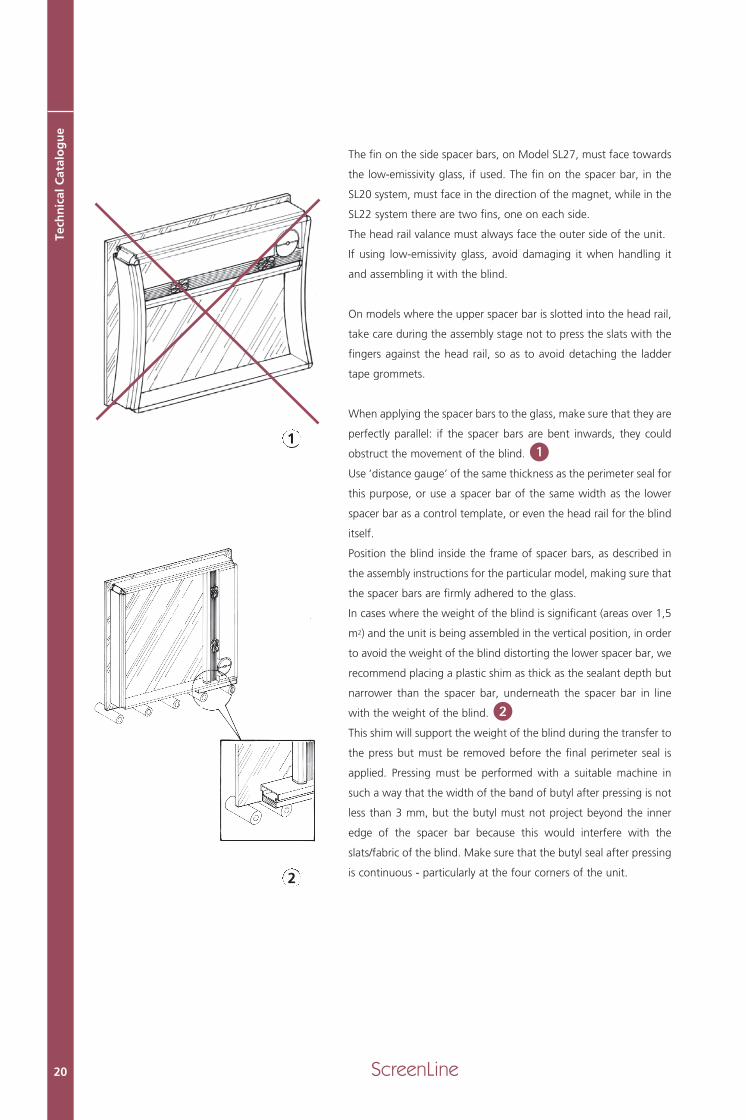
The fin on the side spacer bars, on Model SL27, must face towards
the low-emissivity glass, if used. The fin on the spacer bar, in the
SL20 system, must face in the direction of the magnet, while in the
SL22 system there are two fins, one on each side.
The head rail valance must always face the outer side of the unit.
If using low-emissivity glass, avoid damaging it when handling it
and assembling it with the blind.
On models where the upper spacer bar is slotted into the head rail,
take care during the assembly stage not to press the slats with the
fingers against the head rail, so as to avoid detaching the ladder
tape grommets.
When applying the spacer bars to the glass, make sure that they are
perfectly parallel: if the spacer bars are bent inwards, they could
obstruct the movement of the blind.
Use ‘distance gauge’ of the same thickness as the perimeter seal for
this purpose, or use a spacer bar of the same width as the lower
spacer bar as a control template, or even the head rail for the blind
itself.
Position the blind inside the frame of spacer bars, as described in
the assembly instructions for the particular model, making sure that
the spacer bars are firmly adhered to the glass.
In cases where the weight of the blind is significant (areas over 1,5
m2) and the unit is being assembled in the vertical position, in order
to avoid the weight of the blind distorting the lower spacer bar, we
recommend placing a plastic shim as thick as the sealant depth but
narrower than the spacer bar, underneath the spacer bar in line
with the weight of the blind.
This shim will support the weight of the blind during the transfer to
the press but must be removed before the final perimeter seal is
applied. Pressing must be performed with a suitable machine in
such a way that the width of the band of butyl after pressing is not
less than 3 mm, but the butyl must not project beyond the inner
edge of the spacer bar because this would interfere with the
slats/fabric of the blind. Make sure that the butyl seal after pressing
is continuous - particularly at the four corners of the unit.
1
2
MT parte generale_GB 15-05-2007 10:04 Pagina 20

21ScreenLine
Sealing the double-glazed unit
Use the sealing equipment in the vertical position for preference, to
avoid the glass deflecting under its own weight.
If the sealing is carried out in the horizontal position, make an
equalising hole in a corner where it will not be seen from the inside of
the cavity. The equalising hole must be open when the unit is moved to
the vertical position, and then closed when the sheets of glass have
become parallel. In the event that deflection of the glass persists, use
suction cups to restore parallelism. The distance from the edge of the
glass to the spacer bar must not be less than 3 mm for the entire peri-
meter of the unit. See the manufacturer’s Quality Scheme.
Note. If there is deflection in both sheets of glass making up the dou-
ble-glazed unit (tempered or laminated), put the convex face to the out-
side of the cavity and not to the inside, as shown in the diagram.
Atmosphere inside the unit
To reduce deflection in the double-glazed unit due to the absorption of
the moisture present in the air at the time of assembly, we recommend
the use of argon gas, which is not absorbed by molecular sieves. To fill
the double-glazed unit with argon, drill two holes through the spacer
bar into the unit cavity, and use the standard procedure for replacing
the air with gas when assembling the units. Take care to avoid interfe-
ring with the internal blind, and do not leave swarf from the drilling on
the inside. Seal the holes appropriately, using special sealing plugs, or
some butyl, before carrying out sealing with the sealant for the second
barrier. The use of argon is recommended especially if assembly is car-
ried out in the hot part of the year and in very humid areas (low pres-
sure). Filling the unit with argon gas is performed using gas cylinders
which contain the gas at extremely high pressure. By means of a redu-
cer, this pressure is reduced to very low levels, which allows the gas to
be introduced into the cavity. At the same time, it also causes a drop in
temperature of the glass entering the cavity itself (Law of Gases).
The smaller difference in temperature between the gas (argon) and the
environment in which the unit will be operating in the winter months,
causes a smaller deflection in the sheets of glass which make up the
unit. It is also advisable for the gas-filled cavity to have a slightly higher
pressure than the external environment. To achieve these conditions,
simply close the outlet hole, allowing the gas to flow in for a few
seconds, and then close the entry hole.
3
4
MT parte generale_GB 15-05-2007 10:04 Pagina 21
ScreenLine22
Tech
nic
al C
atal
og
ue
Gas leakage from the unit
If the double-glazed unit is correctly assembled, following the procedures and the quantities of sea-
lant in the first and second sealing specified by standard EN 1279/3, a good seal will be achieved for
the argon with which the unit is filled.
Comparing the loss of gas from a number of units which had been installed for ten years, with mea-
surements taken in specialised laboratories in accordance with DIN 52293 and EN 1279/3, where the
measurements agreed with each other, it was established that the laboratory tests were measuring in
the samples a loss of gas ten times higher than the loss encountered in the installed units. From this
experiment it has been deduced that an insulating glass unit with an annual gas loss lower than 1%
(laboratory test), after artificial ageing, may lose a quantity of gas less than 5% over the course of 25
years starting from its installation on site. According to this estimate, using cautious values, it can be
predicted that an insulating glass unit loses every 10 years an amount of gas double that measured in
the laboratory.
Ideal ambient conditions
The ideal environmental conditions for the assembly of the ScreenLine® kit into the double-glazed
unit are:
• temperature of 15 °C
• relative humidity not higher than 60%
• atmospheric pressure 760 mm Hg
Different conditions (temperature and relative humidity too high, low atmospheric pressure) can,
over time, cause damaging deflection within the double-glazed unit and incorrect operation of the
molecular sieves.
MT parte generale_GB 15-05-2007 10:04 Pagina 22
23ScreenLine
Final Inspection
Testing
Before despatching the double-glazed unit with built-in blind, it is important to carry out checks to
guarantee the quality of the product.
We recommend the following checking procedure:
• Hold the unit vertically, as it will be positioned in the window.
• Check the parallelism of the sheets of glass, i.e. that they are flat, without deflection. This check must
be repeated the next day if argon has not been used.
• Even over a period of time, the two sheets must remain parallel (see the paragraph “atmosphere insi-
de the unit”). The deflection can be measured by placing a straight edge diagonally across each face
of the double-glazed unit or it can be measured with an appropriate laser tool.
• Check the functions of the blind (tilting and raising) using the appropriate control, verifying that the
bottom rail and the blind remain equidistant from the side spacer bars; the bottom rail must reach
the lower spacer bar
• Check that the glass, the blind slats/fabric, the spacer bars and the head rail are perfectly clean.
• Completely raise the blind before shipment. For tilt-only blinds (i.e. those with the bottom rail locked
at the bottom), open the slats before transport.
• To test the SL27M system use only 24V dc power supply.
Note. In the event of deflection in the glass or in the side spacer bars causing the blind to jam as it
descends, do not continue to lower the blind, in order not to damage the internal mechanism or the
cords. Pack (fully raise) the blind, remove the cause of the blockage and retry the operation of the
blind.
Fin
al In
spec
tio
n
MT parte generale_GB 15-05-2007 10:04 Pagina 23

ScreenLine24
Transport and storage
For transporting the insulating glass units with the blind incorpora-
ted, within the factory or en route to the site, the units must be posi-
tioned vertically, with the blind at the bottom of the unit.
Only where the size of the sheets is greater than the permitted ship-
ment height can the unit be laid on its longest side, however in all
cases the slats or the fabric must be packed (fully raised), to avoid
damaging them. In the case of units with low-emissivity glass, place
the non-coated glass to the underside in order to prevent damage to
the coating on the inner side.
Tilting-only blinds must be transported with the head rail of the blind
at the top, and with the slats in the open position , in order to
avoid the blind collapsing.
YES
NO
YES
NO
Stack the finished units using appropriate cork or rubber spacers to avoid the risk of scratching the glass.
Any glass product may be stored on site for a short while, for as long as is necessary for installation. Make
sure in all cases that the double-glazed units with blind incorporated are sheltered from humidity and the
sun, from dust and from harmful materials like cement and lime. The units should be stored vertically on
a level rigid surface in an area away from thoroughfares, in the dry. If the units need to be stored outsi-
de, they should be covered, and spacers should be placed between them to allow the free circulation of
air between the individual units (pads of cork, rubber or any other material that will not damage the glass
surface). The pack of units should be leaning not more than 6° from the vertical and should rest on a sur-
face of soft material. The units should not be stored in direct sunlight, to avoid thermal shock.
Note. Avoid keeping the blind packed (fully raised) for long periods of time. Great care should be taken
with tilt-only models during transport and installation. In fact, after positioning integral double-glazed
units, it is advisable to carry out some tilting manoeuvres on the slats, in order to avoid them being left
for long in the wrong position. If these units are subjected to solar radiation, the slats can deform the lad-
der tape, and it is unlikely that subsequent manoeuvres will enable it to resume its original shape. If this
happens, it can prevent the slats from closing properly.
1
2
Tran
spo
rt a
nd
sto
rag
e
MT parte generale_GB 15-05-2007 10:04 Pagina 24

25ScreenLine
Installation
Installation of the double-glazed units with built-in blind must be car-
ried out in such a way that the blind can move freely between the two
sheets of glass, without being restrained by the glass or by the side
spacer bars.
Correct operation of the blind depends on the way the unit is instal-
led, and not just on complying with the tolerance for cutting the
glass. Check that the glass is flat, if fabrication took place in a plant
at a different altitude from the final location. Use a straight edge on
the external diagonal of the double-glazed unit, or a laser measuring
device. Locate the unit in the window frame, in a perfectly vertical
position so as to allow the internal blind to move freely.
Any corrections can be made after testing the operation of the blind.
The bottom rail must be equidistant from the side spacer bars when
the blind is almost at the bottom. With tilting-only blinds, the slats
should be equidistant from the side spacer bars.
Blinds with front manual magnetic control
On kits with front manual magnetic control, make sure that the exter-
nal control is not covered by the glass retaining bead.
For this purpose, check the overall dimensions for the model concer-
ned in the Handbook.
Use of the centring plate avoids any interference.
Attaching the centring plate
• Clean the area of glass concerned carefully with alcohol.
• Wait several seconds till the alcohol has evaporated and the surfa-
ce of the glass is dry.
• Remove the protection from the adhesive coating on the plate
• Centre the hole in the plate with the magnet inside the head rail,
placing the edges of the plate parallel to the sides of the glass.
• Press the plate firmly with the fingers, avoiding deforming the cen-
tring collar
• Any cork spacers used for transporting the glass must be positioned
around the centring plate as protection
On arrival at the site, the external control must be attached after pla-
cing the double-glazed unit, incorporating the kit, in the window
frame.
1
2
1
3
Inst
alla
tio
nA
ttac
hin
g t
he
cen
trin
g p
late
MT parte generale_GB 15-05-2007 10:04 Pagina 25

ScreenLine26
Att
ach
ing
th
e co
ntr
ol
Attaching the control
• Make sure that the centring plate located on the glass is not cove-
red by the glass retaining bead.
• Position the magnetic control on the plate, moving the cord to put
the two magnets in phase
• Take off the control, and remove the protection from the adhesive
coating on the plate and on the control. Attach the control,
centring it with the collar on the plate itself, making the long side
perfectly parallel with the nearby glass retaining bead on the win-
dow frame.
• Press the control firmly against the plate
• To ensure a secure anchorage, do not perform any manoeuvring
operation for at least 24 hours; on the contrary, press the control
on the glass and move the cord.
Attaching the cord tensioner
• Clean the area of glass concerned carefully with alcohol.
• Wait several seconds till the alcohol has evaporated and the surfa-
ce of the glass is dry.
• Peel off the protection from the adhesive on the back of the cord
tensioner
• Hook the cord loop over its runner on the cord tensioner
• Maintain a slight tension on the cord, with the cord tensioner sli-
der halfway
• Attach the cord tensioner to the glass with suitable pressure,
taking care to position it parallel to the frame and in line with the
control
It is important to note that during the operations described above, it
is essential on no account to touch the exposed parts of the adhesi-
ve with the fingers. If the adhesive does get damaged, it would be
advisable to replace it with fresh adhesive. Do not use other systems
for gluing the control if they do not correspond to the instructions
given above.
5
6
7
2
1
3
Att
ach
ing
th
e co
rd t
ensi
on
er
4 5 6 7
MT parte generale_GB 15-05-2007 10:04 Pagina 26

Blinds with knob control
In the kits with knob control, SL20P and SL24P, leave enough room
between the double-glazed unit and the window frame to accom-
modate the sheathing containing the flexible control cable. Couple
the ends of the cable to the magnet control, sliding the brass tube
over them to lock them together.
Drill the holes in the window frame , allowing the flexible cable
and its sheath to pass through.
Cut the cable to length, leaving about 5 cm projecting from the
hole, and strip the covering sheath from about the last 2 cm.
Locate the knob in the desired position, after using the grub
screw provided to secure the flexible cable (without leaving it pro-
truding).
In the case of the knob fitted with an end-of-travel stop, before fixing
it to the frame, rotate the knob fully clockwise, closing the blind
completely in that direction. Then operate the blind to check that the
end-of-travel stop works correctly (the blind must close completely in
both directions before the stop comes into play). If this does not hap-
pen, remove the knob from the frame, rotate it in the required direc-
tion to close the slats completely and then re-secure it. Do not bend
the sheathing excessively and do not trap it between the frame and
the double-glazed unit.
27ScreenLine
4 5 6
21
3K
no
b c
on
tro
l
7
MT parte generale_GB 15-05-2007 10:04 Pagina 27

Blinds with internal motor
Connect the terminals with eyelets to the electrical contacts at the upper corner of the double-gla-
zed unit, inside the sealant, after taking out the tubes of silicone, if still present, and removing the
excess of sealant around the contacts. Make sure that there is a firm connection between screw and
terminal. Position the cables such that they are not under tension. The motor cables must be well
insulated and isolated from each other, and connections must not be soldered or brazed. Please
ensure that the cables are not trapped by the glass panes, the glazing blocks (distance pieces), or the
glazing gasket. Any holes drilled in the metal frame for the electrical cables must be free of sharp
swarf which could damage the cables.
Connections between an opening window or door, with movable opening contacts, must be located
in a position where they will not be affected by water, somewhere that will not cause short circuits
when opening or closing. In particular, if it is a sliding window or door, the contacts must not be
located at floor level. The recommended location for the contacts is the vertical jamb, for sliding, til-
ting and traditional windows and doors.
The contacts must be positioned in such a way as to close simultaneously.
The warranty on the blind is invalidated if the schemes and suggestions provided to the purchaser
have not been followed.
Blinds with external motor
Position the insulating glass unit in the frame, taking care to leave sufficient space around the inter-
nal magnet for interfacing with the external magnet.
If the glass retaining bead does not provide a cable seal, make a slot in it to accommodate the elec-
trical cables supplying the motor, taking particular care that it does not have any sharp edges which
could jeopardise the cable insulation.
Clean the glass carefully. Remove the motor from its base plate and stick the base plate to the glass,
ensuring it correctly interfaces with the internal magnet.
Slide the motor onto the base until it is in the correct position. To facilitate the operation of assem-
bling the motor to the baseplate, slightly rotate the hexagonal flats protruding from the base plate.
Tidy up the excess length of cable between the double-glazed unit and the frame.
Fit the glass retaining bead, and take care that the electrical cables to the motor are not pinched.
The warranty on the blind is invalidated if the schemes and suggestions provided to the purchaser
have not been followed.
ScreenLine28
Inte
rnal
mo
tor
Exte
rnal
mo
tor
MT parte generale_GB 15-05-2007 10:04 Pagina 28

29ScreenLine
Conditioning
When installation of the unit is complete, the blind should be fully lowered in order for the environ-
ment inside the unit, including the blind components (slats, cords, ladder tape etc), to dry out com-
pletely.
Blinds left packed (fully raised) for a long time can give rise to problems involving the slats sticking
together, due to a suction effect. Moreover, when lowering a blind that has been stacked for a long
time it is possible that the bottom rail does not reach the lower position. In this case, it is recom-
mended to wait some time after lowering, in order to allow the ladder tape to stretch to its full extre-
mity and so reach the bottom.
If the blind encounters an obstruction as it is lowered, stop lowering it, raise the blind and verify the
cause in order to eliminate it.
Operation
The venetian blind is designed to constantly regulate a room’s internal lighting condition and to dar-
ken it in the event of strong solar radiation.
As may be guessed, complete black out cannot be achieved for the following reasons:
• the ladder tape takes up space between the slats
• the slats have holes for the cord to pass through
• there must be clearance on either side of the slats to allow for expansion due to temperature.
The normal closed position for blinds is with the convex side facing outwards so as not to allow the
sun’s rays to enter the interior. Closure in this direction is therefore bound to be more complete.
Tilting the blind in the opposite direction does not achieve complete closure because the sun’s rays
are parallel to the slats and therefore penetrate to illuminate the room.
Considerations on fitting integral blind systems
It is quite common to encounter installations of integral blind systems which have obvious aesthetic
or operational faults such as: imbalance in the internal blind system which shows that the blind is not
hanging perfectly vertical, or leakage of the butyl forming the first barrier into the inside of the cavity,
which inevitably causes the blind to stick, or leads to contamination of the pleated fabric, in the case
of pleated or roller blinds.
IMBALANCE: Often fitters attempt to correct poor closure or opening of the opening light of the win-
dow by spacing the glass after fitting it in the frame, in order to shift the centre of gravity of the unit
to one side or other to correct faults in the operation of the window or door.
This procedure may be acceptable when fitting conventional insulating glass units, but is not correct
when fitting integral glass systems with internal screening such as venetian or shading blinds. Any
faults must therefore be corrected by operating on the window or door itself and not on the posi-
tioning of the integral system.
BUTYL: The other aspect which should not be neglected when fitting a double-glazed unit integra-
ted with a screening system is the importance of the different rates of expansion of the components
in the window system with variations in temperature over the course of the seasons.
MT parte generale_GB 15-05-2007 10:04 Pagina 29

ScreenLine30
Tech
nic
al C
atal
og
ue
Failure to take account of differential expansion can result in leakage of the sealant forming the first
barrier into the inside of the unit.
The correct position for the glass in the frame is shown in the specific handbooks for the individual
models.
glass faces of the integral system
integral blind
rubber or silicone sealing gaskets to avoid water penetration
drainage for any water which does penetrate
frame
support block for the glass (3 mm minimum)
butyl 1st seal
thiokol 2nd seal
molecular sieves
The glass is located in the frame with an expansion joint, formed by silicone sealant or rubber
gaskets.
For correct fitting, it is advisable to ensure pressure no higher than 8 N per cm against the glass retai-
ning bead, to avoid the glass being completely locked in the frame. A maximum load of 10 N per cm
is permitted for brief periods during installation. Greater pressure than this could result in leakage of
the butyl with consequent contamination of the blind components.
The correct fitting procedure is to provide a layer of sealant or a perimeter containment gasket not
less than 2-3 mm in thickness.
Glass, metal frames and spacer bars are materials with different properties and different behaviour
when subjected to identical temperature variations.
Az
M
Ve
R
B
Vi
N
Gr
Gi
Az Az
Gi NN
Ve Ve
R
B B
B
ViGr
M
A
MT parte generale_GB 15-05-2007 10:04 Pagina 30

31ScreenLine
SUPPORT BLOCKS: It is good practice to use blocks for the glass to rest on at the bottom of the
frame, with a minimum thickness of 3 mm. The material used for this purpose should be non-defor-
mable and resistant to atmospheric agents: neoprene rubber or PVC, for example, would be suitable
materials. The integral double-glazed unit must be completely supported on these blocks: the weight
must not be resting on just one of the sheets of glass.
It is important to keep to the correct dimensions for the depth of the contact band within the frame,
i.e. the part of the glass which remains covered by the frame and by the glass retaining bead that
runs round the inside of the frame. The table below gives specifications for this depth (indicated by
the letter “A”), in proportion to the half-perimeter of the unit.
Half-perimeter of the unit “H+L” Depth “A”
Less than 2,5 m 16 mm
Between 2,5 m and 7 m 25 mm
Greater than 7 m 30 mm
If the frame in an integral glazing system has a contact band of less depth than those indicated, the
result will be that the spacer bars and sealing mastic used around the perimeter are visible, which is
undesirable from an aesthetic point of view and hazardous if the unit itself is subjected to wind loa-
ding. The minimum permissible measurement for the thickness of the perimeter frame formed by the
glass retaining bead is 13 mm, if a spacer bar of height 6,5 mm is used, increasing to 16 mm if a spa-
cing profile of height 8 mm is used, assuming that the unit is resting on support blocks of the mini-
mum thickness, i.e. 3 mm. Excessive depth of fixing in the frame could cause breakage due to ther-
mal shock. In this case, reference should be made to the suggestions contained in the relevant regu-
lations, studying each case separately. Special instructions must be followed if the units are made up
of glass of large thickness or with a high capacity for absorbing solar energy.
MT parte generale_GB 15-05-2007 10:04 Pagina 31

Warranty
Sizes and tolerances
ScreenLine® blinds are designed to have a clearance of at least 2,5 mm on each side between the
slats and the spacer bar. This enables free movement of the system and allows for thermal expansion
of the aluminium slats (linear expansion of aluminium: 0,23 mm per metre of length for every 10°C).
Production tolerances for ScreenLine® blinds are:
width +0 mm/-1 mm
height +8 mm/0 mm
Note. The difference in height is determined by the pitch of the ladder tape.
Due to the sum of the tolerances of the cord diameters and of the internal winding mechanism, it is
possible for there to be a slight inclination of the bottom rail when raising the blind. This inclination
is more marked in tall and narrow blinds. It is also possible as a result of shrinkage of the raising
cords, and also of the ladder tape, for the bottom rail to remain raised. It should be remembered that
the materials of which both the cords and the ladder tapes are made undergo shortening as the tem-
perature rises and lengthening as the temperature falls. The coefficient of variation in length which
is characteristic of these materials is about 0,02%/°C. For example, if a blind 1000 mm long under-
goes a temperature increase of 50 °C compared with the temperature of manufacture, it will con-
tract by 10 mm. It is also possible for packing in the ladder tapes and the dead weight of the bot-
tom rail to cause the rail to bend. This bending also occurs to a lesser degree with tilting-only blinds
(with locked bottom rail). As the blind is raised, the folding of the ladder tapes does not occur in a
regular and constant fashion. This variation can cause deviation of the slats from the horizontal as
they pack.
Tolerances for parallelism in the bottom rail
With reference to standard EN 13120, the maximum acceptable inclination of the bottom rail with
respect to the mid-point is +/-7,5 mm (15 mm total), without distinction as to the position of the
blind. The ScreenLine® production standard specifies tolerance measurements with the blind in three
positions.
Low position +/-2 mm
Intermediate position +/-5 mm
High position +/-7 mm
The tolerance must be calculated with respect to the mid-point of the bottom rail.
Tolerances for bending in the bottom rail
Again in accordance with standard EN 13120, the maximum bending of the bottom rail and of the
slats, measured at their mid-point, depends on the width of the blind. The table below gives accep-
table measurements for bending.
ScreenLine32
War
ran
ty
MT parte generale_GB 15-05-2007 10:04 Pagina 32

33ScreenLine
Width of the venetian blind Bending of the slats and bottom rail
Below 1,5 m 5 mm
Between 1,5 mm and 2,5 mm 10 mm
Greater than 2,5 m 15 mm
Incomplete tilting of the slats
Permitted divergence from complete tilting of the slats, again with
reference to EN 13120, is 2% of the total number of slats in the enti-
re blind. It is possible during lowering of the blind for the slats to
remain stuck (see the drawing alongside), assuming the correct posi-
tion only when the tilting manoeuvre is carried out with the blind
fully extended. This is acceptable to the extent that the number of
slats not in the correct position, during the process of lowering, falls
within the range of values listed in the following table.
Number of slats in the blind Maximum number of slats with incomplete tilting
Less than 50 0
From 50 to 100 1
From 100 to 150 3
From 150 to 200 4
More than 200 5
Slat closing angle
The orientation of the slats regulates and controls the brightness in the
room. This function is performed by the ladder tapes, in such a way
that moving the tapes makes the slats tilt.
The angle of the slats when closed must be not less than 60°, measu-
red with respect to an axis perpendicular to the plane of the inner
sheet of glass. The tolerances for this closing angle depend on the
height of the blind. More precisely:
Height of blind Tolerance Minimum closingangle
Up to 1 m 5° 55°
Greater than 1 m 10° 50°
Bottom rail parallelism
Central bending of bottom rail
MT parte generale_GB 15-05-2007 10:04 Pagina 33

ScreenLine34
Tech
nic
al C
atal
og
ue
To carry out a check on the correctness of the slat closure, follow the instructions below, referring to
the drawing reproduced below:
• Close the slats completely with the concave side facing the inside.
• Take up a position 1 m from the inner sheet of glass, after identifying the line on the unit corre-
sponding to eye-level.
• Look outwards at the band hidden by the slats.
• It should not be possible to make out objects behind the unit for a band at least 150 mm in height
below the line of the observer’s eye-level (this corresponds to a slat inclination of about 60°).
Note. As a consequence of this tolerance, it is possible for neighbouring blinds to have different
degrees of closure.
observer1 m
15 cm
MT parte generale_GB 15-05-2007 10:04 Pagina 34

35ScreenLine
Slat angle of travel
In performing their tilting action, the slats must be guaranteed to
swivel through a minimum angle of 90° with respect to the longitu-
dinal axis of the slats.
Slat overlap
The individual slats must overlap for a width exceeding 1 mm at the
maximum closing angle of 60°.
Slat parallelism
The maximum misalignment of the individual slats with respect to the
horizontal position must be less than 2 mm per metre of length. This
measurement is to be carried out at several points on the unit with
the slats oriented horizontally (ref. EN 13120).
Tolerances for external controls
The external operating cord, barring specific requests otherwise,
terminates at 65 mm from the glass sightline, with a tolerance of
+10 mm/-20 mm. The external tilting wand, in the lengths stated in
the catalogue, has a length tolerance of +5 mm/-5 mm.
Non conformity
Assessment of non conformities in ScreenLine® products must be
based on visual observation of the blind fitted inside the cavity of the
double-glazed unit. This assessment relates only to visible elements
of the blind (head rail, slats, bottom rail and spacer bars, if supplied
as part of the ScreenLine® kit). Evaluation of the quality of the glass
is not the subject of this assessment and must be referred to the spe-
cific UNI equivalent standard, which solely and exclusively concerns
the producer of the double-glazed unit.
Assessment procedure
Assessment of the quality of the blind must comply with what is spe-
cified in the following points:
• the double-glazed unit with blind incorporated must be positioned
vertically, as specified for final use
• the blind must be lowered and the slats tilted to approximately 45°
• the observer must be positioned at a distance of 2 m from the unit
with line of sight perpendicular to the surface of the unit on both
sides alternately, as illustrated in the following drawing
• before the assessment, the points of possible non conformity must
not be marked in any way
• the assessment must not be carried out with direct sunlight falling
on the slats.
Slat angle of travel
Slat parallelism
1 m
m
90°
min
.
60°
OUT IN
Minimum angle of travel
Minimum overlap
MT parte generale_GB 15-05-2007 10:04 Pagina 35

ScreenLine36
Tech
nic
al C
atal
og
ue
Criteria for acceptability
The surface of the double-glazed unit must be divided into two zones: perimeter zone and central zone
(see drawing above).
Perimeter zone: corresponds to a 5 cm frame around the unit. This zone therefore includes the head
rail and bottom rail of the blind, the ends of the slats and of the fabric, and of the channel section spa-
cer bars.
Central zone: corresponds to the remaining surface area (excluding the perimeter zone). This zone
includes the central part of the blind, which must display the fewest defects. As regards the elements
making up the blind (head rail, slats, fabric and bottom rail), the following defects are acceptable, bea-
ring in mind that total surface area of the double-glazed unit must be rounded up to the next higher
whole number.
Perimeter zoneInclusions, spots, paint defects.
A maximum of 1 defect with a maximum size of 3 mm per square metre area of double-glazed unit.
Deposits on the slats / stains on the fabric: a maximum of 1 defect with a maximum size of 3 mm
per square metre area of double-glazed unit. For dirt at the ends of the slats, see “abrasion against
the side spacer bars”, described below.
Scratches / marks on the fabric: light scratches, which are not readily visible, are acceptable provi-
ding the sum total does not exceed 30 mm in length. The maximum length of any individual scratch
must not exceed 15 mm.
Central zoneInclusions, spots, paint defects.
A maximum of 1 defect with a maximum size of 2 mm per square metre area of double-glazed unit.
Deposits on the slats / stains on the fabric: a maximum of 1 defect with a maximum size of 2 mm
per square metre area of double-glazed unit.
50
H
L
PERIMETER ZONE
CENTR
AL ZONE
2 m
50
45°
Defect observation
observer
L X H = glass measurements
MT parte generale_GB 15-05-2007 10:04 Pagina 36

37ScreenLine
Scratches / marks on the fabric: light scratches, which are not rea-
dily visible, are acceptable if less than 3 and providing that the maxi-
mum length of any individual scratch does not exceed 10 mm.
Abrasion to the side spacer bars: continual rubbing of the slats
against the side spacer bars, during the stage when the blind is
moving, results after a certain number of manoeuvres in a dark depo-
sit on the slat, which is in fact aluminium dust released by the side
spacer bars. To limit and therefore delay the formation of this depo-
sit, the side spacer bars in the ScreenLine® kit are given a suitable
treatment (patented by Pellini) to keep the colours of the slats
unchanged over time in proximity to the side spacer bars, where con-
tact occurs with the slats. The above treatment to the spacer bars is
stable against solar radiation, and does not give rise to the formation
of any fogging.
With reference to abrasion and the consequent formation of black
dust on the slats, we attach below the IFT Rosenheim Directive,
whose object is to regulate the acceptability or disputability of the
deposit of black dust, with the resultant change in colouration of the
slats used in integrated systems.
1. Check whether 10% of the number of ends of slats show a
change in colouration. Focus on the slat with the most dirt.
2. Determine the depth of colour change according to Table 3.
3. Determine the colour of the slats according to Table 4.
4. Determine the colour of the dirt according to Table 4.
5. Determine the difference between the colour of the slats and the
dirt by the difference in the indicated values.
6. Check whether the requirements are satisfied for permissible
colour alteration according to Table 5.
Table 3 Dirt level (t) of the
ends of the slats
t < 5 mm_
t < 15 mm_
t < 25 mm_
t < 35 mm_
MT parte generale_GB 15-05-2007 10:04 Pagina 37

If the relationship between the two shades of grey is not clearly defined, take the one with the ligh-
ter tone.
Explanatory example
Suppose that the slat used is comparable on the grey-scale to the first colour in Table 4. The colour
contrast can in this case be assessed as 0-20%.
If the dirt on the slat is for example as in the last picture in Table 4, the colour contrast in this case
is between 80% and 100%.
The difference is therefore 80%, and in this case, according to the provisions in Table 5, the heaviest
dirt can cause a colour alteration of up to 15 mm in depth.
Fabric undulation
Model SL27 Rullo, both in the version with cord (System C) and in the motorised version (System M),
can display an undulation in the fabric in the vicinity of the side spacer bars, between which the blind
runs.
The undulation is evident when the observer is positioned at a short distance (less than two metres)
with an angle of observation of less than 90° with respect to the surface of the glass. If this does not
prejudice the operation of the system, in the sense that the blind functions correctly both in the pro-
cess of lowering and in the process of raising, the undulation is not considered a defect.
ScreenLine38
Tech
nic
al C
atal
og
ue
Depth of colour Colour differencealteration
0-20% 20-40% 40-60% 60-80% 100%
t < 5 mm Ok Ok Ok Ok Ok
t < 15 mm Ok Ok Ok Ok No
t < 20 mm Ok Ok Ok No No
t < 35 mm Ok Ok No No No
t > 35 mm No No No No No
Table 4 Colour of the slats and colour difference
0 - 20%
20 - 40%
40 - 60%
60 - 80%
80 - 100%
Table 5 Colour change permitted for the slats
Colour of the slatsColour of the dirt Difference
_
_
_
_
MT parte generale_GB 15-05-2007 10:04 Pagina 38

39ScreenLine
Special applications
ScreenLine® kits have been designed to be assembled inside rectangular insulating glass units, posi-
tioned vertically.
Special applications are also possible:
• inclined and horizontal double-glazed units
• shaped double-glazed units
• structural double-glazed units
• partition windows
We recommend that special applications be referred to our technical department for approval, and
we list below some considerations that should be observed.
• For inclined units, the use of internal blinds with a raise function is not recommended. Friction
of the slats on the glass does not allow the blind to be used correctly, and can cause the ladder
tape to fail. For this reason in such applications we recommend the use of kits with pleated fabric
or of blinds with tilting only (with the slats suitably supported).
• In the case of tilting units, do not operate the blind with the unit in the tilted position, and in
any event fit a stop to the opening light to avoid the unit being turned upside down (in systems
with 180° rotation). Before rotating the window, the blind should be packed (fully raised). In the
case of tilt only blind systems (with the bottom rail fixed down), the window should only be rota-
ted with the slats closed. For both the above applications, we recommend the specially designed
model, with pleated fabric or with tilting-only venetian blind.
• In units fitted to doors, constant slamming of the slats on the glass can cause ladder tape dama-
ge. We therefore recommend fitting effective travel-limiting shock absorbers as part of the door
operating system.
Warning
In low emissivity units, use of hard (pyrolitic) coatings is recommended. In the case of blinds with the
raising function, with the blind fully raised, the ladder tape protrudes from the slats and can come
into contact with the coating on the glass, which is especially delicate if it is a coating deposited by
the magnetronic process.
If this is the case, the venetian blind should be tilting only, and should be fitted with purpose-made
lateral guides with a fin facing towards the treated face of the glass, in order to preserve the inte-
grity of the coating over time.
The fin on the lateral guides does not guarantee that there will be no contact between the low-emis-
sivity glass and the blind.
Spec
ial a
pp
licat
ion
s
MT parte generale_GB 15-05-2007 10:04 Pagina 39

ScreenLine40
Man
ufa
ctu
rer’
s Q
ual
ity
Sch
eme
Manufacturer’s Quality Scheme
In accordance with standards EN 1279 1 - 2 - 3 - 4
The manufacturer of insulating glass units inside which a blind (insert) is fitted, is obliged to comply with
the regulations laid down in EN 1279. These regulations refer both to the materials used and to some
of the production parameters for the units. We list below only the characteristics and documentation
required for the part that concerns the inserts (Chapter 2.2) and the specifications relating to produc-
tion (Chapter 3), ignoring the general section on the raw materials used in a conventional double gla-
zed unit.
Standard EN 1279-1 Chapter 2.2 Spacers and inserts
The product must conform to the characteristics declared by the manufacturer. For the materials used
the licensee must have the following documentation, supplied by the manufacturer and not more than
5 (five) years old:
• characteristics of the product
• control and test procedures
• safety sheet
• fogging test verification under section C and measurement of the quantity of volatile substances
under section G (certificates on this subject for the batch of materials)
• absorption capacity value (Tc) as specified under EN 1279/2.
In addition, each batch must be accompanied by a test report relating to the following:
Spacers with metallic permeabilization profile: a) dimensions; b) quantity of fats; c) volatile con-
tent under section G; d) permeability of the holes; e) sealing capacity of the electro-welding under
section H
Standard EN 1279-1 Chapter 3 Specifications relating to production
3.1 Minimum quantity of internal sealant
• 1,5 g per linear metre on each side of the spacer
• width of band of sealant not less than 3 mm measuring the area effectively pressed.
3.2 Minimum quantity of external sealant
• distance between edge of glass and spacer not less than 3 mm along the entire perimeter of the unit.
3.3 Quantity of dessicant (molecular sieves and silica gel)
For spacers up to 10 mm width, minimum of 3 sides to be filled; for spacers exceeding 10 mm width,
at least 50% of the perimeter to be filled.
Each side must be filled completely.
3.4 If the spacer is not bent at the corners but connected with corner keys
• the corner must be hermetically sealed.
3.5 Interruptions in the band of butyl sealant, holes and/or interruptions in the external sea-
lant
• not permitted.
3.6 A licensee requiring models with gas must possess suitable equipment for checking the gas con-
centration.
3.7 The licensee must seal any holes by a suitable method for preventing leakage of the gases intro-
duced.
MT parte generale_GB 15-05-2007 10:04 Pagina 40

41ScreenLine
Certifications
The quality of the ScreenLine® system is guaranteed by the following principal factors:
• Certification of the Pellini company
• Checks on the materials
• Tests carried out periodically on the product in our internal laboratory
• Certification issued by authorised institutes and laboratories
Standard ISO 9001-2002
The Pellini company is particularly committed to achieving organisational efficiency in order to offer
its customers a quality service and product. For this reason a system of corporate structure has been
put into operation for achieving this object.
This structure is currently made up of a series of instruments and procedures in support of the various
production activities, which enables the company to evaluate and develop the necessary program-
mes for achieving its fixed objectives.
The plan was initially developed on the basis of Standard UNI-ISO 9002:1994 and later adapted to
suit UNI-ISO 9001:2000.
In this way Pellini S.p.A. in 2001 obtained Quality certification for the production and marketing of
technical blinds, blinds for integration into double-glazed units, and related accessories. In 2002, with
the revision of the Standard mentioned above (VISION 2000), Certification was also extended to
include design.
Checks on materials
• Fogging test
In accordance with the provisions of Standard EN 1279-6, all the materials used for the fabrication
of ScreenLine® kits - spacer bars, top rails, motors, slats, cords, ladder tape - are spot-checked on arri-
val at the factory using the tests specified by the above Standard.
Samples of the material are prepared for the purpose, and enclosed inside test-piece double-glazed
units. They are then irradiated with ultra-violet lamps, according to the procedure specified in
EN1279-6. In parallel with this, some of the same material is weighed with a precision balance, and
placed in an electric oven at about 80°C for at least 168 hours. At the end of this period, the mate-
rial is again weighed, thus making it possible to determine any loss of volatile elements from the
material itself.
The products tested are approved or otherwise on the basis of the results of the UV test, at the end
of which cooling plates which are part of the test equipment are applied to the test-piece double-
glazed units containing the material being tested. There must not be any sign of the formation of
condensation in the vicinity of these plates. The samples which are undergoing the test for the loss
of volatile elements are weighed before and after the heat treatment in the electric oven. In this test,
it is the largest value for loss of volatile elements observed in the entire batch which counts.
• Dimensional stability test
A dimensional stability test is carried out on the cords and the ladder tape which constitute the ope-
rating and adjustment system for ScreenLine® blinds. This test has the object of assessing the extent
of the dimensional variation in these components as a result of heat.
Cer
tifi
cati
on
s
MT parte generale_GB 15-05-2007 10:04 Pagina 41
ScreenLine42
Tech
nic
al C
atal
og
ue
The materials from which both the cords and the ladder tape are manufactured undergo a reduction
in length as the temperature inside the double-glazed unit rises, especially during the summer
months. The tests carried out in the Pellini laboratory have the object of verifying that these compo-
nents remain within the preset limits for contraction and subsequent expansion with the change of
temperature. This enables us to calculate the length of the blind in accordance with the measure-
ments required by our customers.
• Magnet stability test
The type and quality of the magnets used in ScreenLine® kits is of crucial importance for the magne-
tic transmission: the magnets must develop a particular torque and must not become demagnetised
as the temperature rises.
For this reason, all the batches of magnets undergo a stability check in our laboratory. A suitable
instrument (torque meter) is used to measure the torque with which one magnet can pull the other,
up to the slippage point, for a given thickness of glass (4 mm), at room temperature (about 20 °C).
Subsequently, the magnets being tested are heated to a temperature of at least 80 °C, and the tor-
que value is again measured. The torque thus measured must show a reduction of no more than
10% from the value measured at room temperature. The test magnets are then left to cool down,
and the torque measurement must return once more to its original value.
This ensures the maintenance over time of the magnetic field necessary for delivering a constant
mechanical driving torque.
• Durability test on the kits
Durability tests are carried out periodically in the Pellini laboratory on kits taken from production with
measurements close to the feasibility limits for the model being tested.
On magnetic systems with manual movement, the kit is operated by an external motor which simu-
lates operation with the external magnetic control.
The parameters of the cycle are similar to those adopted by the certifying institutes CSTB and IFT.
The minimum number of cycles which the system must survive without damage is specified in the
chapter concerning the warranty on the product.
The company is certified The products are certified
MT parte generale_GB 15-05-2007 10:04 Pagina 42

43ScreenLine
Spectro-photometric characteristics of an integrated system
1. Definitions of the faces of an integral system
Starting from the exterior, the faces are numbered 1, 2, 3, 4, the intention being in this way to cla-
rify the effects of the position of any reflective or low-emissivity coating deposited on the glass.
These coatings are frequently used in glazing applications. In the event that laminated glass is being
used, with layers of PVB between sheets of glass, each sheet of glass possesses two faces, and the
numbering therefore follows the succession of the faces of the sheets of glass used.
Thus for example a pane of laminated glass will itself have faces 1, 2, 3, 4, and if used as the first
outer pane in the double-glazed unit, the integrated unit will then have an inner pane with the num-
bering 5, 6.
This system, which is adopted in the international sphere, allows clear characterisation of the units
used, both conventional and integral.
The statements made on the subject in this handbook comply with this convention.
exterior interior
Face 2 Face 4Face 1 Face 3
Spec
tro
-ph
oto
met
ric
char
acte
rist
ics
MT parte generale_GB 15-05-2007 10:04 Pagina 43

ScreenLine44
Tech
nic
al C
atal
og
ue
2. Spectro-photometric characteristics
Diagram showing the principle of the input of solar energy in an integrated system
When solar radiation strikes the outer face of the system (Face 1), part of it is reflected (RE), part of
it is transmitted (TE) directly by the system itself, and part of it is absorbed (AE). The energy absor-
bed is in its turn divided into two parts, in relation to the condition of the faces of the glass: an inte-
rior portion (qi) and an exterior portion (qe).
Whereas the energy transmitted directly has the characteristics of the energy of the solar spectrum,
in other words it has the same waveband as the solar spectrum, the energy corresponding to (qe)
and the energy corresponding to (qi) have a spectrum which belongs to the long infrared, in other
words where λ > 2500nm.
However, the energy entering a room, being due to the solar input, is attributable to the sum of (Te)
and (qi), this sum being indicated by the symbol (g), known as the solar factor.
Room with Standard conditions
The solar irradiation conditions to which integrated systems are subjected depend on many environ-
mental factors such as:
1. Latitude of the installation site
2. Day of the year
3. Angle formed by the wall in which the system is installed, with respect to the ground
4. Angle of the façade with respect to the south or the north
5. Time of day
With these parameters it is possible to calculate the angle of incidence (δ) of the solar radiation with
respect to the wall, and, combining this with the solar constant, to evaluate the radiant power on
the wall itself, expressed in W/m2. The directive published in August 2005 by the IFT institute of
Rosenheim establishes the evaluation criteria for a standard room, suggesting to the designer the ini-
tial parameters for irradiation and ambient temperatures to refer to for an evaluation of the spectro-
photometric parameters of an integrated system.
g = Te + qi
qi
100%
AE
qe
RE
exterior interior
TE
MT parte generale_GB 15-05-2007 10:04 Pagina 44

Winter conditions
Exterior Te = 5°C temperature of ambient air and of irradiation
Es = 300 W/m2 solar irradiation
Interior Te = 20°C temperature of ambient air
Summer conditions
Exterior Te = 35°C temperature of ambient air and of irradiation
Es = 850 W/m2 solar irradiation
Interior Ti = 25°C temperature of ambient air
Taking account of these parameters and those of the system components, it is possible to evaluate
the spectro-photometric characteristics and the thermal transmittance, including cases where there
is a venetian or pleated blind inside the double-glazed unit, positioned with the slats inclined at 30°,
60° or closed; or where, as in the case of systems with pleated or roller blinds, the screening elements
are in the open position (blind raised) or the closed position (blind lowered). The result of this calcu-
lation is obtained by the use of a dedicated computer program based on a mathematical model of
the integrated system. The most significant parameters for the designer, from the point of view of
containing heat dispersion in the winter, or saving energy in the operation of air conditioning systems
in the summer, without neglecting the comfort aspect, are respectively:
Solar factor g %
Direct solar transmission TE %
Light transmission TL %
Colour rendition Ra %
Thermal transmittance U [W/m2]
Brief note on solar radiation
45ScreenLine
B
2.5
2.0
1.5
1.0
0.5
0
0.50 1.0 1.5 2.0 2.5 3.0
Wavelength in mµ
W/m2µ
UV visible
A
MT parte generale_GB 15-05-2007 10:04 Pagina 45

The graph above represents the spectrum of solar radiation. The curve marked A represents solar
radiation outside the earth’s atmosphere, while the curve marked B represents solar radiation within
the earth’s atmosphere.
The energy spectrum represented can be broadly divided as follows:
1. wavelengths with λ< 380nm corresponding to UV energy
2. wavelengths with 380nm <λ< 780nm corresponding to the visible light waveband
3. wavelengths with 780nm <λ< 3000nm corresponding to the short infrared waveband
4. At wavelengths of λ>3000nm but below 50.000nm we have long infrared radiation, correspon-
ding to the thermal energy emitted by a low-temperature heat source (such as for example ordinary
heating appliances or the human body).
When designing an integrated wall, we need to take the electromagnetic energy aspects into
account, separating the field of solar energy waves from the field of energy waves emitted by heat
sources with wavelengths over 3000nm.
Thermal transmittance U-factor [W/m2°K]
The thermal transmittance U-factor corresponds to the transmission of thermal energy from an envi-
ronment at a higher temperature to an environment at a lower temperature.
To increase the general insulation of a building, we need to build walls with as low a U-factor as pos-
sible.
All the glazing used in building today employs the double-glazing system (two sheets of glass sepa-
rated by a cavity).
Thermal transmittance (U-factor) depends on the state of the surface of one or both sheets of glass,
on the width of the cavity (within certain limits), on filling the cavity with particular gases, or on sim-
ple dehydrated air. In particular applications, units with several layers of glass, and therefore compri-
sing more than one cavity, are used, to further increase thermal insulation and therefore achieve a
low U-value.
An effective reduction in transmittance is achieved by using glass surfaces with low emissivity, or by
adding extra surfaces, as in the case of triple - or quadruple-glazed units.
In these cases, the transmission of thermal energy from the environment at a higher temperature to
the environment at a lower temperature is reduced principally by the low total emissivity of the
system, due to the type of surface used (Low E) or to the use of a number of parallel surfaces.
Using venetian or pleated/roller blinds, for example, inside a double-glazed unit, reduces the trans-
mittance value, both because of the particular emissivity of the materials used (aluminium or acrylic
fabric treated with aluminium), and because of the resulting multi-layer conformation which there-
fore has at least two cavities.
The use of venetian or pleated/roller blinds has greater significance from the point of view of obtai-
ning a reduction in U-factor, if the glass used is simple float glass, i.e. not low-emissivity. In the case
of units with low-emissivity surfaces, the effect of the blind for this purpose is not of great signifi-
cance.
The table provides some examples.
ScreenLine46
Tech
nic
al C
atal
og
ue
MT parte generale_GB 15-05-2007 10:04 Pagina 46

The principal object of an integrated system is to modulate the light of the sun, reducing energy
inputs as far as possible, particularly in the summer months, when it is desired to save energy in the
use of conditioning systems for the air inside dwellings. Sometimes, the use of conventional double-
glazed units with external faces (face 2) made of selective glass is not sufficient to ensure a high light
input and a low solar factor. Referring to the graph of the sun’s spectrum, standard glass exhibits
behaviour which is different depending on the wavelength. In fact a large part of the UV radiation
is reduced by the external glass, whereas in respect of the remainder of the waveband, the glass is
very transparent. See the graph below.
47ScreenLine
LE low-emissivity glass
Ey selective glass
Cavities with dehydrated air
1,000,90
0,80
0,70
0,60
0,50
0,40
0,30
0,20
0,10
0,00 0,5 1,0 1,5 2,0 2,5 3,0 3,5 4,0
W/m
2 µ
0,030
0,024
0,013
0,012
0,06
0
0,035
3 4 5 6 8 10 20 30 40 50
Wavelength in mµ
W/m
2 µ
Wavelength in mµ
Energy transmission of a sheet of float glass of thickness 4 mm
Type of unit Type of integral blind U-factorw/m2°k
C4/20/C4 - 2,3 w/m2°k
C4/20/C4 S102 slat 2,1 w/m2°k
C4/20/C4 S156 slat 2,0 w/m2°k
C4/27/C4 816 fabric 1,9 w/m2°k
C4/27/C4 812 fabric 1,6 w/m2°k
C4/20/LE - 1,5 w/m2°k
C4/20/LE S102 slat 1,5 w/m2°k
C4/20/LE S156 slat 1,4 w/m2°k
C4/27/LE 816 fabric 1,3 w/m2°k
C4/27/LE 812 fabric 1,2 w/m2°k
Ey/20/C4 - 1,4 w/m2°k
Ey/20/C4 S102 slat 1,4 w/m2°k
Ey/20/C4 S156 slat 1,4 w/m2°k
Ey/27/C4 816 fabric 1,3 w/m2°k
Ey/27/C4 812 fabric 1,3 w/m2°k
MT parte generale_GB 15-05-2007 10:04 Pagina 47

The energy entering the room through the glass, and interacting with the objects in the room, is con-
verted into energy at a longer wavelength, causing these objects in their turn to emit energy at a
wavelength for which glass is opaque. In this case the room overheats and we thus have a green-
house effect.
3. Colour rendition
One aspect which should not be ignored by the designer is the parameter which concerns colour ren-
dition. The use of selective glasses excludes a large part of the short infrared energy, and if this
occurs, the waveband of the light spectrum is reduced. The result in some cases is an alteration in
the colours in habitable rooms. If we want good colour rendition, it is not possible to reduce the
energy attributable to the visible light waveband without altering the light. In rooms where the light
is particularly important from the point of view of not producing chromatic alterations in the objects
in the room, the parameter for colour rendition cannot be lower than 88%.
When using integral systems we must therefore refer to four basic parameters, namely:
Solar factor g
Direct energy transmission TE
Light transmission TL
Colour rendition Ra
The ideal parameter, which is difficult to achieve with a simple selective double-glazed unit, refers to
the ratio between energy transmission TE and light transmission TL (called the selectivity ratio); it can-
not be less than 57% without penalising colour rendition.
The spectral transmission of an ideal selective glass, represented by the graph above, has the light
waveband between 380nm and 780nm, as the sole cause of energy transmission in the system.
In this range the energy radiation passing through the glass represents 57% of the entire waveband.
It is therefore impossible, in the current state of technological knowledge, to reduce the thermal
energy transmitted without also reducing the light input. The tables below represent several different
cases of integral double-glazed units using: standard glass, low emissivity glass on face 3, and selec-
tive glass on face 2, in combination with venetian blinds of two different colours and several diffe-
rent fabrics for pleated and roller blinds.
ScreenLine48
Tech
nic
al C
atal
og
ue
-20
0
20
40
60
80
100
0 500 1000 1500 2000 2500 3000
Spectral transmission
wavelength (nm)
tran
smis
sio
n %
MT parte generale_GB 15-05-2007 10:04 Pagina 48

49
It may be noted that notwithstanding the fact that the two slats taken as examples (S102 and S156)
are of different colours, they have the same behaviour with regard to solar radiation. In fact, as illu-
strated in the table below, the absorption of solar energy by these two slats is only different by a few
percentage points. The greater reflection from the white slat also produces greater light transmis-
sion, when the slats are at a particular angle. The parameter which is farthest apart from the rest,
however, relates to colour rendition, which is greater for the silver slat (S156) compared with the
white slat (S102). This fact attributes greater selectivity to the white slat, which because of its chro-
matic conformation reflects some colours more strongly than others, and allows a narrower light
waveband to pass through the integral double-glazed unit
ScreenLine
Type of Type of Position Solar Energy Light Colourglass blind of blind factor transmission transmission rendition
C4/20/C4 S102 open 0,78 0,72 0,81 98
C4/20/C4 S102 30° 0,50 0,34 0,41 95
C4/20/C4 S102 60° 0,26 0,07 0,10 89
C4/20/C4 S102 closed 0,21 0,03 0,05 88
C4/20/C4 S156 30° 0,50 0,33 0,37 98
C4/20/C4 S156 60° 0,26 0,06 0,07 96
C4/20/C4 S156 closed 0,22 0,03 0,03 96
C4/20/LE S102 open 0,67 0,58 0,79 99
C4/20/LE S102 30° 0,43 0,28 0,39 96
C4/20/LE S102 60° 0,21 0,06 0,09 90
C4/20/LE S102 closed 0,17 0,03 0,05 88
C4/20/LE S156 30° 0,43 0,27 0,36 98
C4/20/LE S156 60° 0,21 0,05 0,06 97
C4/20/LE S156 closed 0,22 0,02 0,03 97
Ey/20/C4 S102 open 0,44 0,39 0,71 97
Ey/20/C4 S102 30° 0,32 0,19 0,36 95
Ey/20/C4 S102 60° 0,20 0,04 0,08 88
Ey/20/C4 S102 closed 0,17 0,02 0,04 87
Ey/20/C4 S156 30° 0,32 0,18 0,32 97
Ey/20/C4 S156 60° 0,21 0,03 0,06 95
Ey/20/C4 S156 closed 0,17 0,02 0,03 95
MT parte generale_GB 15-05-2007 10:04 Pagina 49

Slat Energy Energy Light Emissivitycolour reflection absorption reflection ε%
RE% AE% RL%
S102 70% 31% 78% 80%
S149 68% 32% 75% 75%
S156 65% 35% 62% 59%
S142 65% 35% 69% 67%
S106 62% 38% 72% 71%
S130 58% 42% 65% 82%
S125 57% 43% 63% 79%
S157 43% 57% 44% 67%
S155 42% 59% 48% 82%
ScreenLine50
Tech
nic
al C
atal
og
ue
Table of the spectro-photometric characteristics of the ScreenLine® slats
Table of the spectro-photometric characteristics of the Verosol® fabrics
Colour Weight g/m2 RE% AE% TE% RL% AL% TL% ε812 95 71% 20% 9% 66% 25% 9% 0,25
878 106 74% 21% 5% 74% 21% 5% 0,25
816 72 52% 28% 20% 50% 28% 22% 0,25
Spectro-photometric data for various integral systems with ScreenLine® pleated or roller blinds
Type of Type of Position Solar Energy Light Colourglass blind of blind factor transmission transmission rendition
C4/27/C4 raised O,78 0,72 0,81 98
C4/27/C4 812 closed 0,25 0,08 0,09 98
C4/27/C4 816 closed 0,40 0,21 0,24 98
C4/27/LE raised 0,67 0,58 0,79 99
C4/27/LE 812 closed 0,21 0,07 0,08 98
C4/27/LE 816 closed 0,34 0,17 0,23 98
Ey/27/C4 raised 0,44 0,39 0,71 97
Ey/27/C4 812 closed 0,18 0,04 0,08 96
Ey/27/C4 816 closed 0,27 0,12 0,21 96
MT parte generale_GB 15-05-2007 10:04 Pagina 50

Even in the case of the fabric blinds, the colour of the light is not altered. The colours of the slats or
fabrics interfere with the sunlight, in a way that depends on the composition of the colour. The white
colour of slat S102, for example, is made up of red, blue and green, each of which reflects a pro-
portion of the energy of the corresponding frequency attributable to the same colour, and thus cau-
ses the modification of the light transmitted.
The silver colour of slat S156 and of the fabrics of the pleated and roller blinds, does not substantially
alter the light transmitted, since grey is neutral with respect to the entire light waveband.
Composition of the colour white
Colours partly reflected by the white slat
The light transmitted through an integral system with white slats is made up for the most part of the
colours violet, light blue, yellow and orange. The colour rendition is therefore partially reduced.
Note. The use of blinds outside the cavity, located at about 150 mm from the inner pane of glass,
does not convey any advantage compared with an integral system. If for example we use a unit with
composition Ey/20/C4/150/S156 (a case already considered above), the solar factors with slat inclina-
tion 30°, 60°, or closed are about 5% higher than for an integral system where the identical compo-
nents are used. In addition, the glass inside the room could reach a temperature about 10 °C higher
than that of the glass in an integral unit made up of the same components. The same condition obtains
if we use a roller blind with fabric 812. In this case, the solar factor of the system is about 4 points
higher than that of the corresponding integral system, and the temperature of the inner glass is about
5 °C higher.
51ScreenLine
Green
Blue
Red
Violet Light blueBlue Blue Yellow Orange Red RedGreen
R R R
Green
White
MT parte generale_GB 15-05-2007 10:04 Pagina 51

4. Energy balance
An important aspect of the use of integral systems becomes clear in the assessment of the energy
balance.
An ideal integral system should have behaviour which adapts to the needs of the summer and win-
ter seasons. We should therefore attribute to it the following characteristics:
Period Transmittance (U-factor) Solar factor (g)
Winter Low High
Summer Low Low
No system of traditional insulating glass units, whether it is made up of selective glass or of low-emis-
sivity glass, can achieve this performance, except within certain limits.
An integral system can achieve this kind of adaptation by correcting the solar factor through the
regulation of the angle of the slats (or by opening or closing a pleated or roller blind). It can do this,
for example, by exploiting the greater reflectivity of some types of slat in the infrared band of the
sun’s spectrum (780nm-3000nm - see the graph below).
Example of calculating an energy balance
Let us take a building with windows which face in a known compass direction, and take into account
the temperature inside the building, the external winter temperature and the external summer tem-
perature. Let us furthermore consider the periods of sunshine according to the annual data for the
area we are referring to. In this way it is possible to determine the energy balance for the walls under
consideration.
With these data, we can study the energy balance (solar input less thermal losses) in the winter
period. In the summer period however, assuming the cooling energy of an air conditioning system
to be a positive input, the solar input and the heat transmission between outside and inside (becau-
se of the temperature differential) must be considered unwanted inputs from the point of view of
energy saving. The total energy balance (BT) is given by the algebraic sum of the contributions to the
balance in the winter period (Bi) and in the summer period (Be):
BT = Bi+Be
ScreenLine52
Tech
nic
al C
atal
og
ue
0
10
20
30
40
50
60
70
80
90
100
0 500 1000 1500 2000 2500 3000
S102
S156
gold
S157
Spectra of various slats
wavelength (nm)
refl
ecti
on
%
MT parte generale_GB 15-05-2007 10:04 Pagina 52
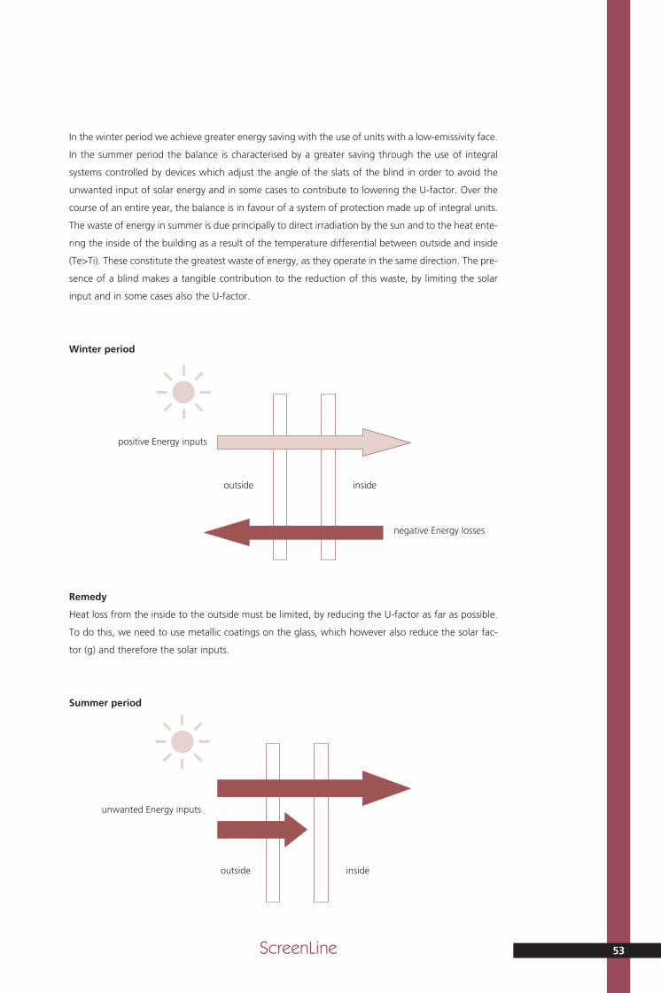
53ScreenLine
In the winter period we achieve greater energy saving with the use of units with a low-emissivity face.
In the summer period the balance is characterised by a greater saving through the use of integral
systems controlled by devices which adjust the angle of the slats of the blind in order to avoid the
unwanted input of solar energy and in some cases to contribute to lowering the U-factor. Over the
course of an entire year, the balance is in favour of a system of protection made up of integral units.
The waste of energy in summer is due principally to direct irradiation by the sun and to the heat ente-
ring the inside of the building as a result of the temperature differential between outside and inside
(Te>Ti). These constitute the greatest waste of energy, as they operate in the same direction. The pre-
sence of a blind makes a tangible contribution to the reduction of this waste, by limiting the solar
input and in some cases also the U-factor.
Winter period
Remedy
Heat loss from the inside to the outside must be limited, by reducing the U-factor as far as possible.
To do this, we need to use metallic coatings on the glass, which however also reduce the solar fac-
tor (g) and therefore the solar inputs.
Summer period
positive Energy inputs
negative Energy losses
outside inside
unwanted Energy inputs
outside inside
MT parte generale_GB 15-05-2007 10:04 Pagina 53

Remedy
We need to limit solar inputs and the heat entering the building as a result of the temperature dif-
ferential between inside and outside (Te>Ti). To reduce solar irradiation and heat inputs, we must
increase the reflectivity of the surfaces and reduce the emissivity of the integral system. In order to
do this we must adopt automated integral systems which become active in unfavourable circum-
stances, for example, by reacting to heat loss in winter and to unwanted solar inputs in the summer
by closing the blinds, or by responding to favourable situations, such as the acquisition of solar
energy in the winter, by opening these same blinds. In this way, it is possible to make significant
energy savings, simply by adjusting the angle of the slats.
Details of the solar factor in an integral system
A study was made of three types of insulating glass units made up respectively as follows:
• two sheets of 4 mm float glass
• one sheet of 4 mm float glass and one sheet of 4 mm low-emissivity glass, forming face 3
• 4 mm low-emissivity glass with coating on face 2, and one sheet of 4 mm float glass
Calculations were made to show the way the solar factor (g) changes with variation in the angle of
the slats of an integral blind. Calculations were then made to show the effects on the temperature
(Ti) in the cavity, and on the secondary energy (qi) radiated towards the inside of a building, resul-
ting from differences in inclination of these same slats of an integral blind. The results are shown in
the graphs below.
The maximum temperature inside the cavity is reached with a slat angle of approximately 45°.
Beyond this value, the temperature stabilises at the value it has reached (see graph below).
ScreenLine54
Tech
nic
al C
atal
og
ue
0
10
20
30
40
50
60
70
80
90
0 20 40 60 80 100
c4-c4
c4-E4
E4-c4
Variation in solar factor for different compositions of unit
slat angle (degrees)
valu
e %
MT parte generale_GB 15-05-2007 10:04 Pagina 54

55ScreenLine
0
10
20
30
40
50
60
70
80
90
0 20 40 60 80 100
4-4
4-Ey4
Ey4-4
25
c4-c4
c4-E4
E4-c4
20
15
10
5
0
40 0 20 60 80 100
It may further be noted that with the slats inclined at an angle greater than 45°, in the case of units
made with a sheet of low-emissivity glass, located once on face 3 and once on face 2, the solar fac-
tor increases slightly in the latter case. In fact, the value (qi) for the unit with low-emissivity glass on
face 2 is greater when the angle of the slats is above 45°, because the emissivity of face 3 is higher
and it therefore radiates more heat towards the interior, also impacting on the solar factor.
Temperature within cavity for different compositions
slat angle (degrees)
tem
per
atu
res
in °
C
Secondary energy for different compositions
slat angle (degrees)
valu
e %
MT parte generale_GB 15-05-2007 10:04 Pagina 55

ScreenLine56
Tech
nic
al C
atal
og
ue
5. Mechanical stresses of thermal origin
There are some aspects of the use of integral systems which should not be underestimated, to which
we will now turn our attention. The first concerns the temperature rise inside the double-glazed unit,
when the solar radiation is intercepted by the blind, whether it be venetian, pleated or roller type.
The screening elements, such as slats or fabric blinds, heat up by absorbing energy. If low-emissivity
glass on face 3 and very absorbent slats or fabric have also been used, temperatures of about 80°C
can be reached.
It is therefore advisable, as has already been noted, to use materials with the lowest possible coef-
ficient of absorption, and to use selective glass on face 2. It is however possible for fairly high tem-
perature differences to develop between the blind and the inner sheet of glass, particularly in the
area of the edges, where glass breakage can occur. It is important to pay attention to the edges of
the glass, especially if it is laminated, or very thick and therefore liable to breakage if heated to high
temperatures, because of the presence of cutting flaws. Special care should be taken in the case of
triple-glazed units, where the use of tempered glass is recommended for the internal sheet (second
sheet), because it is subject to greater thermal stress. The graph below shows the temperature of
the slats depending on their energy absorption and on the position of the low-emissivity glass in the
unit.
0
20
40
60
80
100
120
20 30 40 50 60
Screenline slat colour S102 S149 S156 S142 S106 S130 S125 S157 S155
Energy absorption 31% 32% 35% 35% 38% 42% 43% 57% 59%
standard glass
lowE -3 glass
lowE -2 glass
Temperature of slats
energy absorption of slats %
tem
per
atu
res
in °
C
MT parte generale_GB 15-05-2007 10:04 Pagina 56

The graphs below represent the results of some tests carried out on a real wall in a building The test
refers to the measurement of the temperatures at the centre of the outer and inner sheets of glass,
comparing these measurements with those of the temperatures at the edges of the same glass, in
proximity to the joints, in the case of units used without venetian blinds and in the case of units with
integral venetian blinds.
57ScreenLine
-10
-5
0
5
10
15
20
25
30
35
0 5 10 15 20 24
Temperature variation in outer glass with blind
time of day
tem
per
atu
res
in °
C
-10
-5
0
5
10
15
20
25
30
35
5 10 15 20 240
temperature at centre of glass (°C )
temperature at edge (°C )
Temperature variation in outer glass
time of day
tem
per
atu
res
in °
C
temperature at centre of glass (°C )
temperature at edge (°C )
MT parte generale_GB 15-05-2007 10:04 Pagina 57

ScreenLine58
Tech
nic
al C
atal
og
ue
0
5
10
15
20
25
30
35
40
0 5 10 15 20 24
0
10
20
30
40
50
60
0 5 10 15 20 24
temperature at centre of glass (°C )
temperature at edge (°C )
temperature at centre of glass (°C )
temperature at edge (°C )
Temperature variation in inner glass
time of day
tem
per
atu
res
in °
C
Temperature variation in inner glass with blind
time of day
tem
per
atu
res
in °
C
MT parte generale_GB 15-05-2007 10:04 Pagina 58

59ScreenLine
This difference can cause mechanical stress of thermal origin.
It should be pointed out that exposing an integral system to solar radiation inevitably entails over-
heating all the parts which make up the system.
If the screening system consists of just the insulating glass unit, the temperatures are different bet-
ween the various components according to the absorption characteristics of the sheets of glass
which make up the unit. The presence of a venetian or pleated blind, or again of a roller blind, within
the cavity in the unit, means that the temperature of the various elements increases, given that the
integral screening elements contribute to this increase for all the components in the system. Not only
this, but even the air or gas inside the unit increases in temperature.
It follows that leaving the venetian blind or any other screening element, such as a roller or pleated
blind, in an intermediate position, i.e. not completely open or completely closed, can lead to a non-
homogeneous temperature distribution across the face of the glass.
If the surface of the glass is partly covered by the screening element, it will have a higher tempera-
ture compared with the surface of the same sheet not covered by the venetian blind or more gene-
rally by the integral screen.
Using the integral screening elements in this way must be discouraged, if it is done for long periods
of time.
6. Thermal bridges
The problem of thermal bridges is an aspect in the field of the application of building materials which
concerns not just insulating glass units fitted in a frame, but all materials used in construction, and
it arises whenever the insulation of a wall needs to be tackled as a whole.
In the specific case of insulating glass units, the first thermal bridge is caused by the actual joint in
the unit itself, formed by the spacing channel section and the mastics, the molecular sieves, and at
a later stage by the frame into which the unit itself is fitted.
When integral systems are being used, the problem extends to the venetian blind itself which is inte-
grated into the insulating glass unit, the reason being that the blind is fabricated from materials
which are better conductors of heat than the air or gas in the cavity where it is housed.
The table below provides some examples of thermal transmittance (U-factor) of insulating glass units
made with two sheets of standard float glass, and with one sheet of float and one of low-emissivity
glass. The object is to assess the effect of the thermal bridges formed by the unit’s perimeter spacer,
compared with the U-value measured at the centre of the unit. The calculation then provides a com-
parison of these same units with units using integral venetian blinds with closed slats.
Double-glazed unit of length 3 m and height 2 m
Type of system Theoretical Actual
transmittance transmittance
6/27/6 2,7W/m2°K 2,8W/m2°K
6/27integral/6 2,2W/m2°K 2,3W/m2°K
6/27/6LowE 1,5W/m2°K 1,59W/m2°K
6/27integral/6LowE 1,5W/m2°K 1,62W/m2°k
MT parte generale_GB 15-05-2007 10:04 Pagina 59

Pelli
niS.
p.A
.vi
a Fu
sari
, 19
• 26
845
Co
do
gn
o (
LO)
ITA
LIA
T
. + 3
9 03
77 4
6641
1 •
F. +
39
0377
437
635
• in
fo@
pel
lini.n
et
Edit
ion
05.
07
www.pellini.net
visu
al d
esig
n: s
tefa
no
sib
on
i.it
engl
ish
Tech
nic
al C
atal
og
ue
Scre
enLin
e
Gen
eral
sec
tio
n
ScreenLine®
MT copertina parte generale_GB 7-05-2007 13:35 Pagina 1