MS14 Military Qualified Splitter - Chronos Technology Ltd · The MS14 splitter comes with many...
14
Page 1 of 14 Your source for quality GNSS Networking Solutions and Design Services, Now! Doc. Desc.: 1x4 Mil Spec GPS Splitter Doc. Number: 1565-TS-GPS-1x4-Mil-Spec-Splitter-04 Revision: 004 Author: Brandie Chenoweth Department: Marketing Date: May 21, 2012 MS14 Military Qualified Splitter Technical Product Data Features • Designed & Manufactured to Military Specifications • Amplified & Passive Versions Available • Passes GPS, Galileo & GLONASS L1/L2 • Excellent Gain Flatness Gain | L1 - L2 | < 2 dB Description The military qualified MS14 GPS splitter is a one-input, four-output GPS device. This product typically finds application where an input from an active GPS roof antenna is split evenly between four receiving GPS units. The MS14 can be configured to pass DC from an RF output (J2) to the antenna input port (J1) in order to power an active GPS antenna on that port. The remaining RF outputs (J3, J4, and J5) would feature a 200 Ohm DC load to simulate an antenna DC current draw for any receiver connected to that port. Alternatively, the MS14 can be configured with a MIL-STD-704 compliant 28 VDC Power Supply that will power the active GPS antenna connected to J1. The MS14 splitter comes with many available options to meet your specific needs. Please call, fax, email ([email protected] ), or visit our website (www.gpssource.com ) for further information on product options and specifications. This device is designed for military applications and environments where high reliability is required. This device has been designed and/or tested to the following MIL standards. MIL-STD-810 MIL-E-5400 MIL-STD-1472 MIL-HDBK-454 MIL-STD-202 MIL-STD-1587 MIL-STD-883 MIL-STD-461 MIL-STD-704 MIL-STD-1275B
-
Upload
duongkhuong -
Category
Documents
-
view
222 -
download
0
Transcript of MS14 Military Qualified Splitter - Chronos Technology Ltd · The MS14 splitter comes with many...

Page 1 of 14 Your source for quality GNSS Networking Solutions and Design Services, Now!
Doc. Desc.: 1x4 Mil Spec GPS Splitter Doc. Number: 1565-TS-GPS-1x4-Mil-Spec-Splitter-04 Revision: 004 Author: Brandie Chenoweth Department: Marketing Date: May 21, 2012
MS14 Military Qualified Splitter
Technical Product Data Features
• Designed & Manufactured to Military Specifications
• Amplified & Passive Versions Available
• Passes GPS, Galileo & GLONASS L1/L2
• Excellent Gain Flatness
Gain | L1 - L2 | < 2 dB Description
The military qualified MS14 GPS splitter is a one-input, four-output GPS device. This product typically finds application where an input from an active GPS roof antenna is split evenly between four receiving GPS units. The MS14 can be configured to pass DC from an RF output (J2) to the antenna input port (J1) in order to power an active GPS antenna on that port. The remaining RF outputs (J3, J4, and J5) would feature a 200 Ohm DC load to simulate an antenna DC current draw for any receiver connected to that port. Alternatively, the MS14 can be configured with a MIL-STD-704 compliant 28 VDC Power Supply that will power the active GPS antenna connected to J1. The MS14 splitter comes with many available options to meet your specific needs. Please call, fax, email ([email protected]), or visit our website (www.gpssource.com) for further information on product options and specifications. This device is designed for military applications and environments where high reliability is required.
This device has been designed and/or tested to the following MIL standards. MIL-STD-810 MIL-E-5400
MIL-STD-1472 MIL-HDBK-454 MIL-STD-202 MIL-STD-1587 MIL-STD-883 MIL-STD-461 MIL-STD-704 MIL-STD-1275B
Page 2 of 14 Your source for quality GNSS Networking Solutions and Design Services, Now!
Doc. Desc.: 1x4 Mil Spec GPS Splitter Doc. Number: 1565-TS-GPS-1x4-Mil-Spec-Splitter-04 Revision: 004 Author: Brandie Chenoweth Department: Marketing Date: May 21, 2012
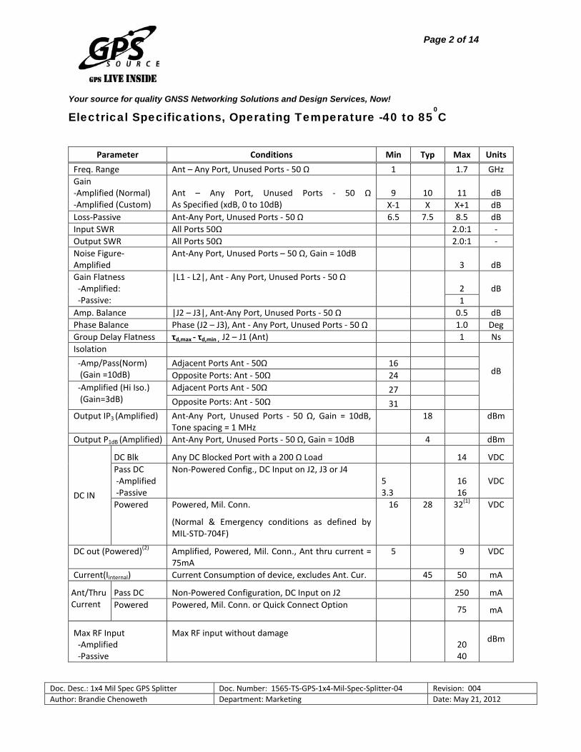
Electrical Specifications, Operating Temperature -40 to 850C
Parameter Conditions Min Typ Max Units Freq. Range Ant – Any Port, Unused Ports - 50 Ω 1 1.7 GHz Gain -Amplified (Normal) -Amplified (Custom)
Ant – Any Port, Unused Ports - 50 Ω As Specified (xdB, 0 to 10dB)
9
10
11 dB
X-1 X X+1 dB Loss-Passive Ant-Any Port, Unused Ports - 50 Ω 6.5 7.5 8.5 dB Input SWR All Ports 50Ω 2.0:1 - Output SWR All Ports 50Ω 2.0:1 - Noise Figure-Amplified
Ant-Any Port, Unused Ports – 50 Ω, Gain = 10dB 3 dB
Gain Flatness -Amplified: -Passive:
|L1 - L2|, Ant - Any Port, Unused Ports - 50 Ω
2
dB
1 Amp. Balance |J2 – J3|, Ant-Any Port, Unused Ports - 50 Ω 0.5 dB Phase Balance Phase (J2 – J3), Ant - Any Port, Unused Ports - 50 Ω 1.0 Deg Group Delay Flatness τd,max - τd,min , J2 – J1 (Ant) 1 Ns Isolation
dB -Amp/Pass(Norm) (Gain =10dB)
Adjacent Ports Ant - 50Ω 16 Opposite Ports: Ant - 50Ω 24
-Amplified (Hi Iso.) (Gain=3dB)
Adjacent Ports Ant - 50Ω 27 Opposite Ports: Ant - 50Ω 31
Output IP3 (Amplified) Ant-Any Port, Unused Ports - 50 Ω, Gain = 10dB, Tone spacing = 1 MHz
18 dBm
Output P1dB (Amplified) Ant-Any Port, Unused Ports - 50 Ω, Gain = 10dB 4 dBm
DC IN
DC Blk Any DC Blocked Port with a 200 Ω Load 14 VDC Pass DC -Amplified -Passive
Non-Powered Config., DC Input on J2, J3 or J4 5 3.3
16 16
VDC
Powered Powered, Mil. Conn.
(Normal & Emergency conditions as defined by MIL-STD-704F)
16 28 32(1) VDC
DC out (Powered)(2) Amplified, Powered, Mil. Conn., Ant thru current = 75mA
5 9 VDC
Current(Iinternal) Current Consumption of device, excludes Ant. Cur. 45 50 mA
Ant/Thru Current
Pass DC Non-Powered Configuration, DC Input on J2 250 mA Powered Powered, Mil. Conn. or Quick Connect Option 75 mA
Max RF Input -Amplified -Passive
Max RF input without damage
20 40
dBm
Page 3 of 14 Your source for quality GNSS Networking Solutions and Design Services, Now!
Doc. Desc.: 1x4 Mil Spec GPS Splitter Doc. Number: 1565-TS-GPS-1x4-Mil-Spec-Splitter-04 Revision: 004 Author: Brandie Chenoweth Department: Marketing Date: May 21, 2012
Notes:
1. By design 1275B spike & surge protection assumes a 28 volt system, 33.3 V or greater will trigger over voltage protection circuitry.
2. DC output voltage to the antenna port (J1) may be specified by customer: 5V, 7.5V or 9V (default is 5V).
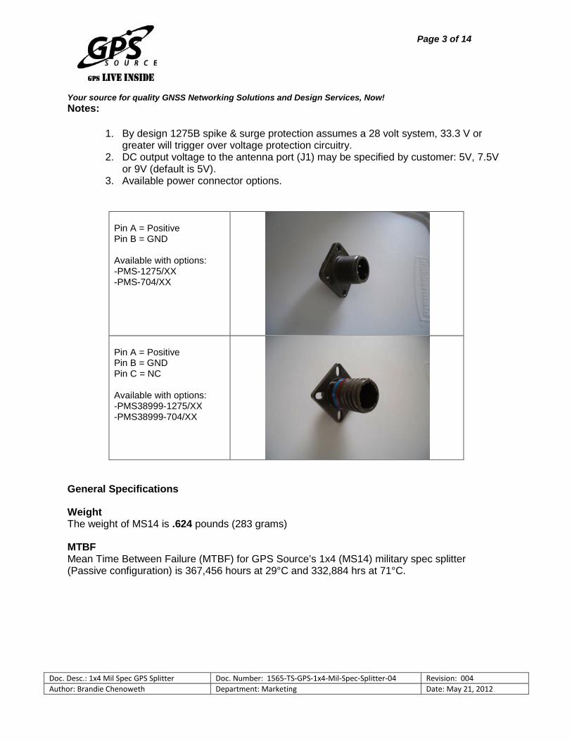
3. Available power connector options.
Pin A = Positive Pin B = GND Available with options: -PMS-1275/XX -PMS-704/XX
Pin A = Positive Pin B = GND Pin C = NC Available with options: -PMS38999-1275/XX -PMS38999-704/XX
General Specifications
Weight The weight of MS14 is .624 pounds (283 grams)
MTBF Mean Time Between Failure (MTBF) for GPS Source’s 1x4 (MS14) military spec splitter (Passive configuration) is 367,456 hours at 29°C and 332,884 hrs at 71°C.

Page 4 of 14 Your source for quality GNSS Networking Solutions and Design Services, Now!
Doc. Desc.: 1x4 Mil Spec GPS Splitter Doc. Number: 1565-TS-GPS-1x4-Mil-Spec-Splitter-04 Revision: 004 Author: Brandie Chenoweth Department: Marketing Date: May 21, 2012
Environmental Specifications
Temperature and Altitude The MS14 complies with the temperature-altitude tests per MIL-STD-810C, Method 504, and Category 5.
Explosive Atmosphere The MS14 is designed for operation in the presence of explosive mixtures of air and jet fuel without causing explosion or fire at atmospheric pressures corresponding to altitudes from −1,800 feet to 50,000 feet The MS14 does not produce surface temperatures or heat in excess of 400°F. The MS14 does not produce electrical discharges at an energy level sufficient to ignite the explosive mixture when the equipment is turned on or off or operated. The MS14 is designed to meet the requirements of MIL-STD-810C, Method 511.1, and Procedure II. Hermetically sealed equipment meeting the Requirements of MIL-STD-202, Method 112D, or MIL-STD-883, Method 1014.7 (as applicable), and not exceeding a Helium leakage rate of 1 x 10⁻⁷ cc/sec, are exempt from this requirement.
Salt Fog The MS14 meets the requirements of Salt Fog conditions per Paragraph 3.2.24.9 of MIL-E-5400. The MS14 can withstand a salt concentration of 5 percent at a temperature of 35o C for 48 hours without degradation.
Fungus The MS14 meets the requirements of Fungus conditions per Paragraph 3.2.24.8 of MIL-E-5400 i.e. fungus inert materials per requirement 4 of MIL-HDBK-454. MS14 can withstand exposure to 95% relative humidity at a temperature of 30o C for 28 days.
Humidity The MS14 is capable of meeting the requirements of a ten-day humidity test conducted per MIL-STD-810C, Method 507.1, Procedure I.
Sand & Dust The MS14 meet be capable of meeting the requirements of Sand and Dust conditions of method 510 of MIL-STD-810C, for a temperature of 145°F for duration of 22 hours.
Vibration The MS14 is designed to meet the requirements of random vibration per conditions (MIL-STD-810C, Method 514.2, and Procedure 1A) to the levels defined below. Acceleration power spectral density (PSD) for the random vibration envelope is shown in Figure 1. Amplitudes for the functional levels and endurance level requirements are as shown in Figure 1.

Page 5 of 14 Your source for quality GNSS Networking Solutions and Design Services, Now!
Doc. Desc.: 1x4 Mil Spec GPS Splitter Doc. Number: 1565-TS-GPS-1x4-Mil-Spec-Splitter-04 Revision: 004 Author: Brandie Chenoweth Department: Marketing Date: May 21, 2012
Figure 1

Page 6 of 14 Your source for quality GNSS Networking Solutions and Design Services, Now!
Doc. Desc.: 1x4 Mil Spec GPS Splitter Doc. Number: 1565-TS-GPS-1x4-Mil-Spec-Splitter-04 Revision: 004 Author: Brandie Chenoweth Department: Marketing Date: May 21, 2012
Shock The MS14 is designed to withstand the shock levels specified in the Shock spectrum of Figure 3. and the saw tooth shock pulse parameter specified in Figure 2.
Figure 2

Page 7 of 14 Your source for quality GNSS Networking Solutions and Design Services, Now!
Doc. Desc.: 1x4 Mil Spec GPS Splitter Doc. Number: 1565-TS-GPS-1x4-Mil-Spec-Splitter-04 Revision: 004 Author: Brandie Chenoweth Department: Marketing Date: May 21, 2012
Figure 3
Page 8 of 14 Your source for quality GNSS Networking Solutions and Design Services, Now!
Doc. Desc.: 1x4 Mil Spec GPS Splitter Doc. Number: 1565-TS-GPS-1x4-Mil-Spec-Splitter-04 Revision: 004 Author: Brandie Chenoweth Department: Marketing Date: May 21, 2012
Decompression The MS14 is designed to meet the performance standards during and following a rapid and complete loss of normal cabin compartment pressurization (10,000 ft.) from an airplane flight altitude of 50,000 feet within 15 seconds. The MS14 will remain operating for 5 minutes at 50,000 feet before being returned to normal cabin pressure.
Overpressure MS14 is capable of withstanding, for 3 minutes, while not operating, a 12.1 psi compartment pressure with no physical distortion or permanent set. The MS14 will operate satisfactorily upon return to normal pressure.
Temperature Shock The MS14 will withstand without degradation (while not operating) Method 503.1, Procedure I of MIL-STD-810C.
Flammability The MS14 is self-extinguishing or nonflammable and meets the Requirements of Paragraph 5.2.4 of MIL-STD-1587 and requirement 3 of MIL-HDBK-454. Finish and Colors
All case surfaces of the MS14 is treated with chemical film per MIL-DTL-5441, TYPE II, CLASS 3. The MS14 bottom contact surface is free of paint, or non-conductive finishes. The MS14 bottom contact surfaces are protected from corrosion by a conductive coating (MIL-DTL-5541).All other surfaces, except connector mating surfaces are primed per MIL-PRF-23377, TYPE 1 CLASS C and painted per MIL-PRF-85285, TYPE 1 COLOR NUMBER ( 26231), military gray (not lusterless variety) per FED-STD-595 (exceptions are bottom and connector surfaces are free of paint).
Human Factors Human Engineering principles and criteria (including considerations for human capabilities and limitations) using MIL-STD-1472 in all phases of design, development, testing, and procedures development. The design is free of all sharp edges, according to MIL-STD-1472.

Page 9 of 14 Your source for quality GNSS Networking Solutions and Design Services, Now!
Doc. Desc.: 1x4 Mil Spec GPS Splitter Doc. Number: 1565-TS-GPS-1x4-Mil-Spec-Splitter-04 Revision: 004 Author: Brandie Chenoweth Department: Marketing Date: May 21, 2012
Electromagnetic Interference and Compatibility Test Electromagnetic compatibility requires that the GPS MS14 perform its intended function and that its operation does not degrade the performance of other equipment or subsystems. The following table defines the test requirements and test procedures for conducting the required electromagnetic compatibility testing.
The MS14 is designed to meet the following requirements of MIL-STD-461E:
Test Description CE102 Conducted Emissions, Power Leads, 10 kHz to 10 MHz CE106 Conducted Emissions, Antenna Terminal, 10 kHz to 40 GHz CS101 Conducted Susceptibility, Power Leads, 30 Hz to 150 kHz CS103 Conducted Susceptibility, Antenna Port, Intermodulation, 15 kHz to10 GHz CS105 Conducted Susceptibility, Antenna Port, Cross-Modulation, 30 Hz to 20 GHz CS114 Conducted Susceptibility, Bulk Cable Injection, 10 kHz to 200 MHz CS115 Conducted Susceptibility, Bulk Cable Injection, Impulse Excitation CS116 Conducted Susceptibility, Damped Sinusoidal Transients, Cables and Power
Leads, 10 kHz to 100 MHz RE102 Radiated Emissions, Electric Field, 10 kHz to 18 GHz RS103 Radiated Susceptibility, Electric Field, 2 MHz to 40 GHz
Electrical Power Service Conditions The MS14 is able to accommodate the +28 VDC aircraft power. Consequently, it must perform its intended function when supplied with the Normal, Emergency and Starting Operation types of electrical power defined by MIL-STD-704F. The transfer operation, as defined by MIL-STD-704F, shall not change the operating mode or damage the MS14.
The MS14 is designed to meet the following test requirements of MIL-STD-704F:
Paragraph Description MIL-STD-704F, 5.3.2 DC Full Performance Characteristics, 28 VDC system MIL-STD-704F, 5.3.2.1 Normal Operation MIL-STD-704F, 5.3.2.2 Abnormal Operation MIL-STD-704F, 5.3.2.3 &5.3.2.4
DC Steady State Voltage in the Emergency or Starting Operation

Page 10 of 14 Your source for quality GNSS Networking Solutions and Design Services, Now!
Doc. Desc.: 1x4 Mil Spec GPS Splitter Doc. Number: 1565-TS-GPS-1x4-Mil-Spec-Splitter-04 Revision: 004 Author: Brandie Chenoweth Department: Marketing Date: May 21, 2012
Performance Data:
MS14 – Passive
Figure 4. Gain vs. Frequency for Passive MS14 Splitter
Figure 5. SWR vs. Frequency Plot for Passive MS14 Splitter

Page 11 of 14 Your source for quality GNSS Networking Solutions and Design Services, Now!
Doc. Desc.: 1x4 Mil Spec GPS Splitter Doc. Number: 1565-TS-GPS-1x4-Mil-Spec-Splitter-04 Revision: 004 Author: Brandie Chenoweth Department: Marketing Date: May 21, 2012
MS14 – Active
Figure 6. Gain vs. Frequency Plot for Active MS14 Splitter
Figure 7. SWR vs. Frequency Plot for Active MS14 Splitter

Page 12 of 14 Your source for quality GNSS Networking Solutions and Design Services, Now!
Doc. Desc.: 1x4 Mil Spec GPS Splitter Doc. Number: 1565-TS-GPS-1x4-Mil-Spec-Splitter-04 Revision: 004 Author: Brandie Chenoweth Department: Marketing Date: May 21, 2012
Available Options:
Power Supply Options: Source Voltage Options Voltage Input Type
DC 16-28 VDC Military Style Connector Output Voltage Options(1) DC Voltage Out
5 7.5 9
RF Connector Options: Connector Options Connector Type Limitations
N (Female/Male) SMA (Female/Male) TNC (Female/Male)
Port Options: Pass DC(1) All Ports Pass DC DC Blocked(1) J3,J4,J5 is DC Blocked & 200Ω Load, DC is passed J2 to
ANT(J1)
More Notes: 1. With source voltage option, any or all RF ports (input or output) can be DC
Blocked or can pass the powered DC voltage

Page 13 of 14 Your source for quality GNSS Networking Solutions and Design Services, Now!
Doc. Desc.: 1x4 Mil Spec GPS Splitter Doc. Number: 1565-TS-GPS-1x4-Mil-Spec-Splitter-04 Revision: 004 Author: Brandie Chenoweth Department: Marketing Date: May 21, 2012
Part Number:
MS14 – A – PMS / 5 – SF
Product: Military Qualified
1x4 Splitter (Pass DC J2-Ant (J1), Block DC- J3, J4, J5) Gain Option: A – Amplified AS – Amplified Custom Gain by Port AXX – Custom Gain (XXdB) Blank – Passive
Source Voltage: PMS-1275 – Military Connector (User supplies DC
& 1275B Compliant) PMS-704 – Military Connector (User supplies DC & 704F Compliant PMS38999-1275 - Military 38999 Connector & 1275B Compliant PMS38999-704 – Military 38999 Connector & 704F Compliant Blank – Pass DC J2-Ant (J1), Block DC-J3 Output Voltage: (3.3 Passive Only), 5, 7.5, 9V Connector Options: NF – N, Female SF – SMA, Female TF – TNC, Female NM – N, Male SM – SMA, Male TM – TNC, Male
For help in creating the part number to meet your exact needs, contact us at [email protected] or visit our website at www.gpssource.com.
Page 14 of 14 Your source for quality GNSS Networking Solutions and Design Services, Now!
Doc. Desc.: 1x4 Mil Spec GPS Splitter Doc. Number: 1565-TS-GPS-1x4-Mil-Spec-Splitter-04 Revision: 004 Author: Brandie Chenoweth Department: Marketing Date: May 21, 2012
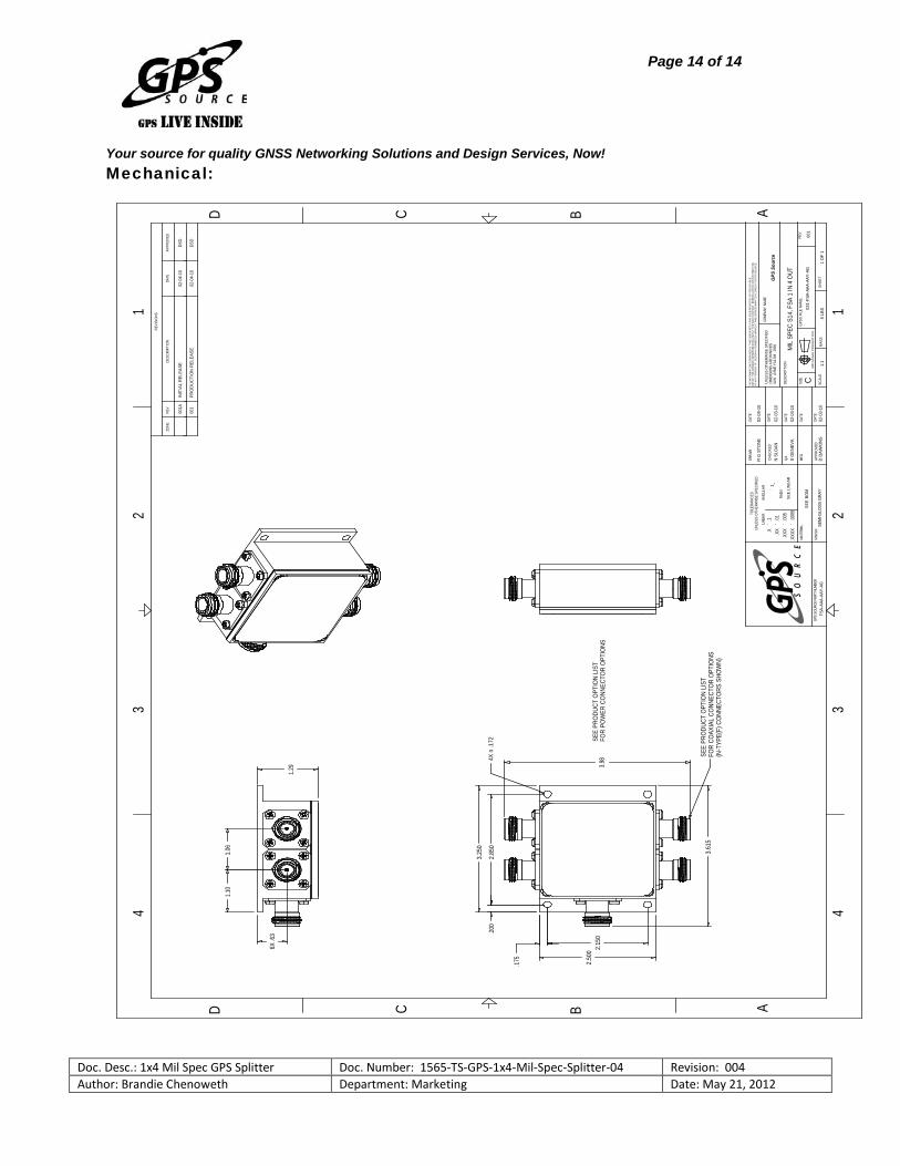
.200
3.25
0
2.85
0
.175
2.15
02.
500
3.61
5
4X n
.172
3.98 SE
E PR
ODUC
T OP
TION
LIS
T FO
R CO
AXIA
L CO
NNEC
TOR
OPTI
ONS
(N-T
YPE(
F) C
ONNE
CTOR
S SH
OWN)
SEE
PRO
DUCT
OPT
ION
LIST
FOR
POW
ER C
ONN
ECTO
R O
PTIO
NS
1.06
6X .6
3
1.10
1.29
APPR
OVED
C
TOLE
RANC
ESUN
LESS
OTH
ERW
ISE
SPEC
IFIE
D
LINEA
R
AN
GULA
R
RAD
II
3RD
AN
GLE
PR
OJE
CT
ION
1:1
MAS
S
02-0
4-10
SEE
BOM
CDESC
RIPT
ION
D
GPS
Sou
rce
DATE
1 1
GPS
S FI
LE N
AME.
B
DATE
CHEC
KED
3 3
UNLE
SS O
THER
WIS
E SP
ECIF
IED
DIME
NSIO
NS A
RE IN
INCH
ESIA
W
ASME
Y14
.5M
- 199
4DA
TE
DRAW
N
4
APPR
OVED
AM
IL S
PEC
S14,
FSA
1 IN
4 O
UT
REVI
SION
S
R G
STO
NE
4
MFG
FSA-
AAA-
AAY-
AG
SIZE
.5 L
BS
QA
1 O
F 1
REV
GPS
SOUR
CE P
ART
NUMB
ER
2
SEE
LIN
EAR
SEM
I-GLO
SS G
RAY
DATE
DESC
RIPT
ION
DATE
001
COMP
ANY
NAME
B
SHEE
T
C
D
MATE
RIAL
SCAL
E
REV
DATE
031-
FSA-
AAA-
AAY-
AG
THE
INFO
RM
ATIO
N C
ON
TAIN
ED IN
TH
IS D
ESIG
N S
ET IS
TH
E SO
LE P
RO
PER
TY O
F G
PS S
OU
RC
E.
USE
OF
THIS
DES
IGN
IS R
ESER
VED
EXC
LUSI
VELY
FO
R S
AID
CO
MPA
NY.
REP
RO
DU
CTI
ON
OR
DIS
TRIB
UTI
ON
OF
ANY
POR
TIO
N O
F D
ESIG
N IS
FO
RBI
DD
EN W
ITH
OU
T TH
E EX
PRES
S W
RIT
TEN
CO
NSE
NT
OFG
PS S
OU
RC
E.
ZONE
A
FINI
SH
2
N S
LOAN
S G
ENEV
A
D D
AWKI
NS
02-0
3-10
02-0
3-10
02-0
3-10
.X
`.1
.XX
`.0
1.X
XX
`.0
05.X
XXX
`.0
005
`1_
001A
001
INIT
IAL
REL
EASE
PRO
DU
CTI
ON
REL
EASE
DSD
DSD
02-0
4-10
02-0
4-10
Mechanical: