MR-2644 Remote LCD Annunciator - Secutron Introduction 1.0 Introduction 1.1 General Features The...
24
LT-2017SEC Rev.2 February 2011 © Secutron MR-2644 Remote LCD Annunciator Installation and Operating Manual
Transcript of MR-2644 Remote LCD Annunciator - Secutron Introduction 1.0 Introduction 1.1 General Features The...

LT-2017SEC Rev.2February 2011
© Secutron
MR-2644Remote LCD Annunciator
Installation and Operating Manual


3
Table of Contents
Table of Contents
1.0 Introduction 7
1.1 General Features ............................................................................................................ 71.2 Contact Us ...................................................................................................................... 81.2.1 General Inquiries ............................................................................................................ 81.2.2 Customer Service ........................................................................................................... 81.2.3 Technical Support ........................................................................................................... 81.2.4 Website ........................................................................................................................... 81.3 Ordering Information ....................................................................................................... 8
2.0 Preparing to Install the MR-2644 9
2.1 Unpacking the MR-2644 ................................................................................................. 9
3.0 Specifications 10
3.1 Environmental Specifications ......................................................................................... 103.2 Electrical Specifications .................................................................................................. 103.3 Transmission Format ...................................................................................................... 103.4 Wiring Specifications ...................................................................................................... 103.5 Physical Dimensions ...................................................................................................... 11
4.0 Installing the MR-2644 13
4.1 Wiring ............................................................................................................................. 134.1.1 MR-2400 Control Unit ..................................................................................................... 134.1.2 MR-2100/2200 Control Unit ............................................................................................ 144.1.3 MR-2900 Control Unit ..................................................................................................... 154.2 Connecting Multiple MR-2644 Annunciators .................................................................. 164.3 MR-2644 Jumper Settings .............................................................................................. 16
5.0 Mounting 17
5.1 Flush Mounting ............................................................................................................... 175.2 Surface Mounting ........................................................................................................... 17
6.0 Operating the MR-2644 18
6.1 Displays .......................................................................................................................... 186.2 Controls .......................................................................................................................... 186.3 Miscellaneous ................................................................................................................. 18
4
Table of Contents
7.0 Warranty and Warning Information 19
7.1 Warning Please Read Carefully .................................................................................... 197.2 Note to Installers ............................................................................................................ 197.3 System Failures ............................................................................................................. 197.3.1 Inadequate Installation ................................................................................................... 197.3.2 Power Failure ................................................................................................................. 197.3.3 Failure of Replaceable Batteries .................................................................................... 197.3.4 Compromise of Radio Frequency (Wireless) Devices ................................................... 207.3.5 System Users ................................................................................................................. 207.3.6 Automatic Alarm Initiating Devices ................................................................................. 207.3.7 Software ......................................................................................................................... 207.3.8 Alarm Notification Appliances ........................................................................................ 207.3.9 Telephone Lines ............................................................................................................. 217.3.10 Insufficient Time ............................................................................................................. 217.3.11 Component Failure ......................................................................................................... 217.3.12 Inadequate Testing ........................................................................................................ 217.3.13 Security and Insurance .................................................................................................. 217.4 Limited Warranty ............................................................................................................ 217.4.1 International Warranty .................................................................................................... 217.4.2 Conditions to Void Warranty .......................................................................................... 227.5 Warranty Procedure ....................................................................................................... 227.6 Disclaimer of Warranties ................................................................................................ 227.7 Out of Warranty Repairs ................................................................................................ 22
5
List of Figures and Tables
List of Figures and Tables
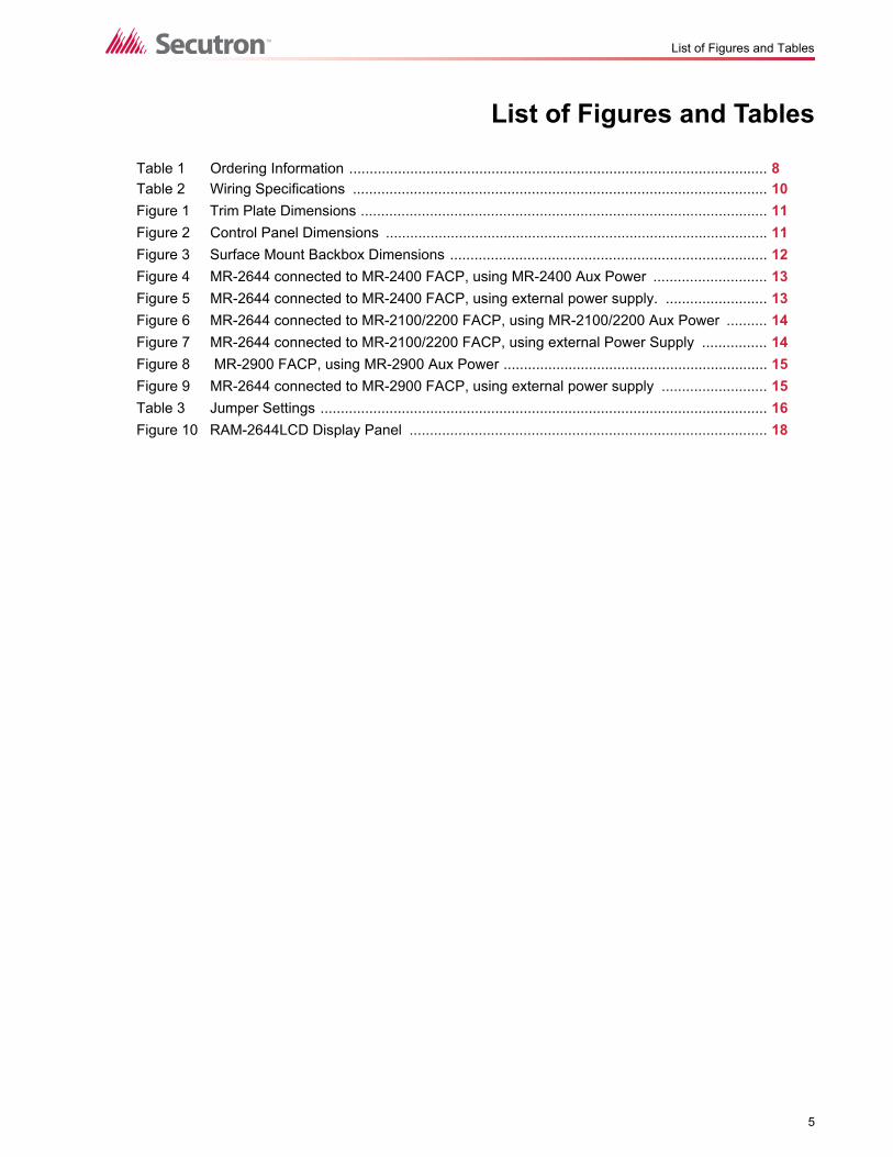
Table 1 Ordering Information ....................................................................................................... 8Table 2 Wiring Specifications ...................................................................................................... 10Figure 1 Trim Plate Dimensions .................................................................................................... 11Figure 2 Control Panel Dimensions .............................................................................................. 11Figure 3 Surface Mount Backbox Dimensions .............................................................................. 12Figure 4 MR-2644 connected to MR-2400 FACP, using MR-2400 Aux Power ............................ 13Figure 5 MR-2644 connected to MR-2400 FACP, using external power supply. ......................... 13Figure 6 MR-2644 connected to MR-2100/2200 FACP, using MR-2100/2200 Aux Power .......... 14Figure 7 MR-2644 connected to MR-2100/2200 FACP, using external Power Supply ................ 14Figure 8 MR-2900 FACP, using MR-2900 Aux Power ................................................................. 15Figure 9 MR-2644 connected to MR-2900 FACP, using external power supply .......................... 15Table 3 Jumper Settings .............................................................................................................. 16Figure 10 RAM-2644LCD Display Panel ........................................................................................ 18

6
List of Figures and Tables

7
Introduction
1.0 Introduction1.1 General Features
The MR-2644 is a remote annunciator for use with Secutron's MR-2400, MR-2100/MR-2200,and MR-2900 Fire Alarm Control Panels with the following features:
• For ULC-S527-99, MR-2644 must be used with MR-2614 LED Annunciator
• Designed to meet the requirements of NFPA 72, 2002 Edition, and UL864, Control Units for Fire Protective Systems, 1996 Edition
• 80-character Liquid Crystal Display (LCD)
• Six common system status lights for Alarm (red), Supervisory (yellow), Trouble (yellow), Monitor (yellow), AC On (green), and Ground Fault (yellow)
• Four system hotkeys for Ack, Silence, Reset, and Lamp Test
• Access-controlled Silence and Reset hotkeys – require the keyswitch to be in the "enable" position.
• Four sets of scroll keys for Alarm, Supervisory, Trouble and Monitor
• Up to eight MR-2644 annunciators can be connected to the MR-2400, MR-2100/MR-2200 or MR-2900 Fire Alarm Control Panels. The MR-2644 has three programming jumpers located on the back of the module. They are used to select one of the 8 supervision addresses.
• All annunciators display the same information during normal system operation.
8
Introduction
1.2 Contact Us
For General Inquiries, Customer Service and Technical Support you can contact us Monday toFriday 8:00 A.M. to 5:00 P.M. E.S.T.
1.2.1 General Inquiries
Toll Free 1-888-732-8876 (North America Only)
Local 905-660-4655
Email [email protected]
1.2.2 Customer Service
Toll Free 1-888-MIRCOM5 (North America Only)
Local 905-695-3535
Toll Free Fax 1-888-660-4113 (North America Only)
Local Fax 905-660-4113
Email [email protected]
1.2.3 Technical Support
Toll Free 1-888-MIRCOM5 (North America Only)
888-647-2665
International 905-647-2665
Email [email protected]
1.2.4 Website
www.secutron.com
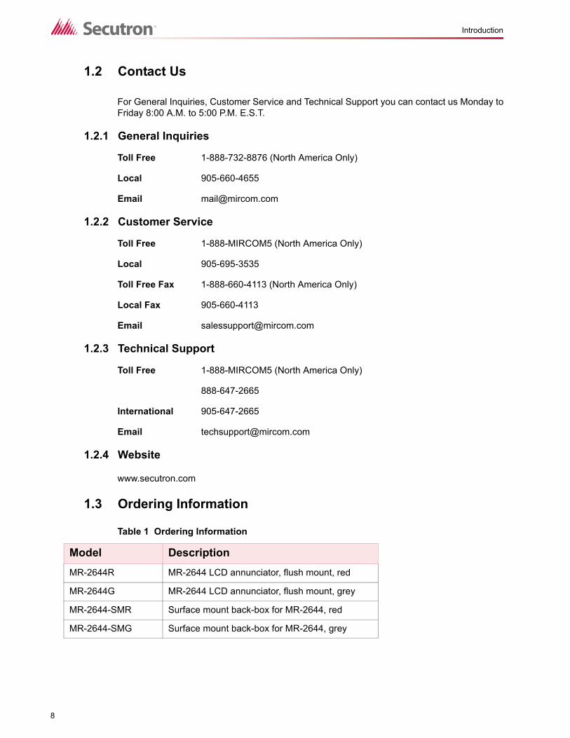
1.3 Ordering Information
Table 1 Ordering Information
Model DescriptionMR-2644R MR-2644 LCD annunciator, flush mount, red
MR-2644G MR-2644 LCD annunciator, flush mount, grey
MR-2644-SMR Surface mount back-box for MR-2644, red
MR-2644-SMG Surface mount back-box for MR-2644, grey
9
Preparing to Install the MR-2644
2.0 Preparing to Install the MR-26442.1 Unpacking the MR-2644
• Flush mount annunciator assembly
• Trim ring• Display plate with label and keyswitch• Main and sub printed circuit boards
• Installation Manual
• Hardware Pack
• Keys to keyswitch• Four (4) mounting screws• Four (4) mounting screws for trim plate
10
Specifications
3.0 Specifications3.1 Environmental Specifications
3.2 Electrical Specifications
3.3 Transmission Format
Multiplexed, supervised, power limited
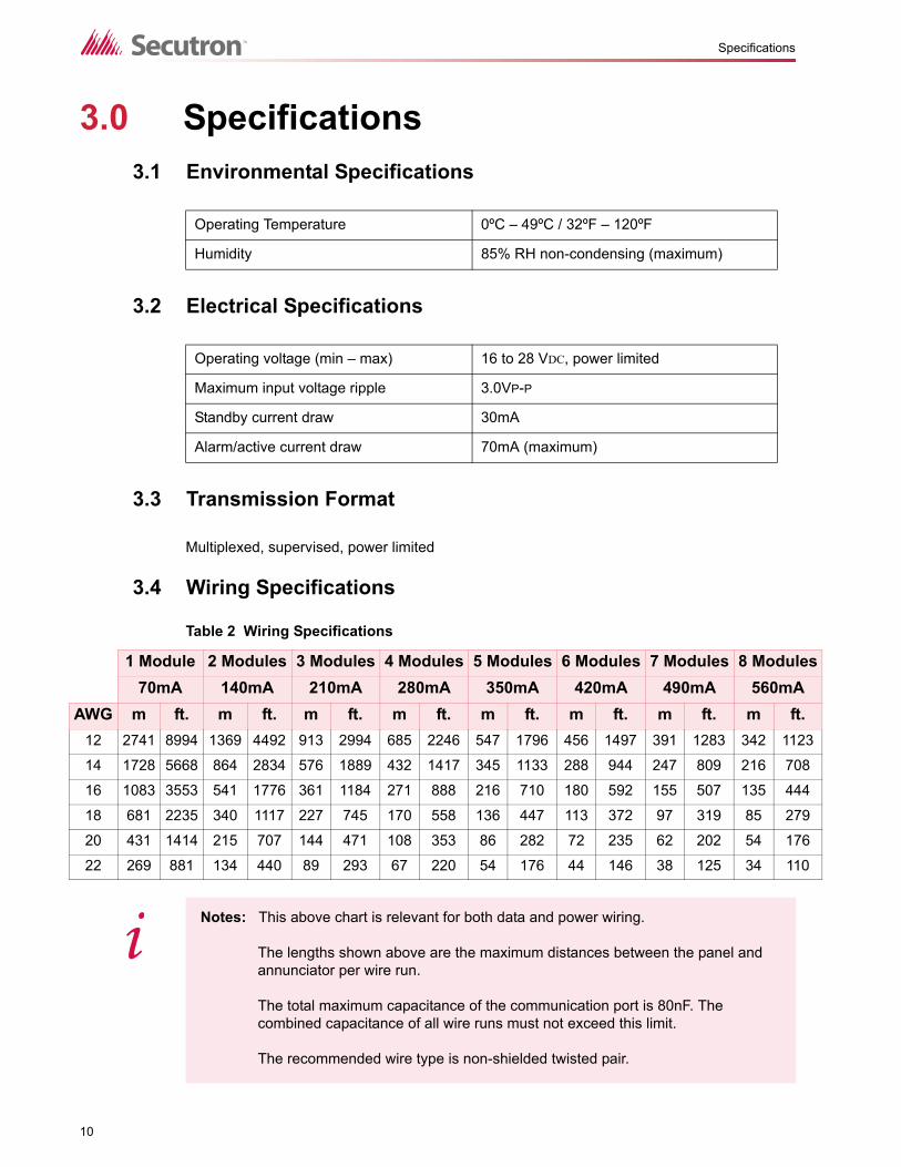
3.4 Wiring Specifications
Operating Temperature 0ºC – 49ºC / 32ºF – 120ºF
Humidity 85% RH non-condensing (maximum)
Operating voltage (min – max) 16 to 28 VDC, power limited
Maximum input voltage ripple 3.0VP-P
Standby current draw 30mA
Alarm/active current draw 70mA (maximum)
Table 2 Wiring Specifications
1 Module 2 Modules 3 Modules 4 Modules 5 Modules 6 Modules 7 Modules 8 Modules70mA 140mA 210mA 280mA 350mA 420mA 490mA 560mA
AWG m ft. m ft. m ft. m ft. m ft. m ft. m ft. m ft.12 2741 8994 1369 4492 913 2994 685 2246 547 1796 456 1497 391 1283 342 1123
14 1728 5668 864 2834 576 1889 432 1417 345 1133 288 944 247 809 216 708
16 1083 3553 541 1776 361 1184 271 888 216 710 180 592 155 507 135 444
18 681 2235 340 1117 227 745 170 558 136 447 113 372 97 319 85 279
20 431 1414 215 707 144 471 108 353 86 282 72 235 62 202 54 176
22 269 881 134 440 89 293 67 220 54 176 44 146 38 125 34 110
Notes: This above chart is relevant for both data and power wiring.
The lengths shown above are the maximum distances between the panel and annunciator per wire run.
The total maximum capacitance of the communication port is 80nF. The combined capacitance of all wire runs must not exceed this limit.
The recommended wire type is non-shielded twisted pair.
i
11
Specifications
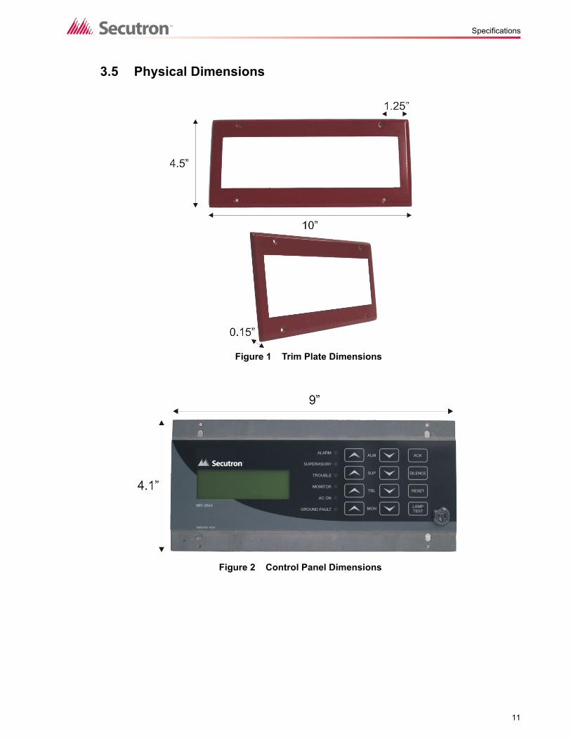
3.5 Physical Dimensions
Figure 1 Trim Plate Dimensions
Figure 2 Control Panel Dimensions

12
Specifications
Figure 3 Surface Mount Backbox Dimensions
13
Installing the MR-2644
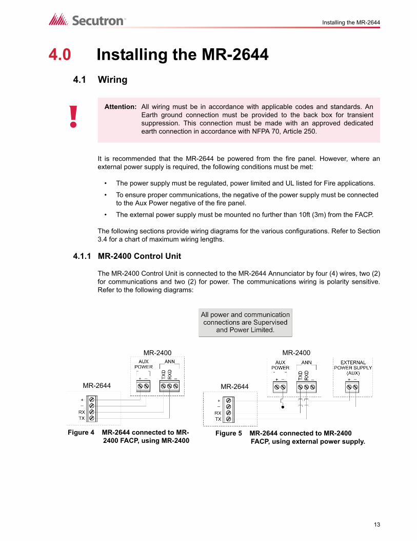
4.0 Installing the MR-26444.1 Wiring
It is recommended that the MR-2644 be powered from the fire panel. However, where anexternal power supply is required, the following conditions must be met:
• The power supply must be regulated, power limited and UL listed for Fire applications.
• To ensure proper communications, the negative of the power supply must be connected to the Aux Power negative of the fire panel.
• The external power supply must be mounted no further than 10ft (3m) from the FACP.
The following sections provide wiring diagrams for the various configurations. Refer to Section3.4 for a chart of maximum wiring lengths.
4.1.1 MR-2400 Control Unit
The MR-2400 Control Unit is connected to the MR-2644 Annunciator by four (4) wires, two (2)for communications and two (2) for power. The communications wiring is polarity sensitive.Refer to the following diagrams:
Attention: All wiring must be in accordance with applicable codes and standards. AnEarth ground connection must be provided to the back box for transientsuppression. This connection must be made with an approved dedicatedearth connection in accordance with NFPA 70, Article 250.
!
Figure 4 MR-2644 connected to MR-2400 FACP, using MR-2400
MR-2644
MR-2400 MR-2400
MR-2644
Figure 5 MR-2644 connected to MR-2400 FACP, using external power supply.
14
Installing the MR-2644
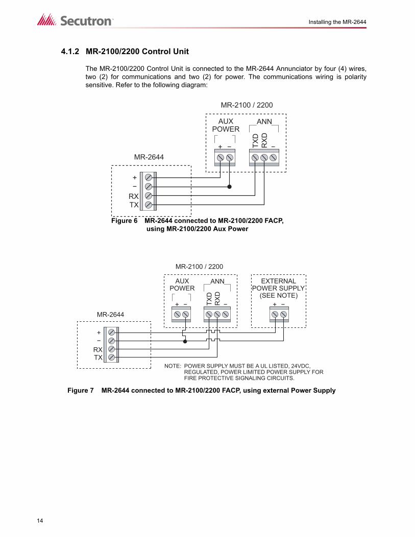
4.1.2 MR-2100/2200 Control Unit
The MR-2100/2200 Control Unit is connected to the MR-2644 Annunciator by four (4) wires,two (2) for communications and two (2) for power. The communications wiring is polaritysensitive. Refer to the following diagram:
AUXPOWER
MR-2100 / 2200
MR-2644
ANN
TXD
RX
D
RXTX
Figure 6 MR-2644 connected to MR-2100/2200 FACP, using MR-2100/2200 Aux Power
AUXPOWER
EXTERNALPOWER SUPPLY
(SEE NOTE)
ANN
NOTE: POWER SUPPLY MUST BE A UL LISTED, 24VDC,REGULATED, POWER LIMITED POWER SUPPLY FORFIRE PROTECTIVE SIGNALING CIRCUITS.
TXD
RX
D
RXTX
MR-2100 / 2200
MR-2644
Figure 7 MR-2644 connected to MR-2100/2200 FACP, using external Power Supply
15
Installing the MR-2644
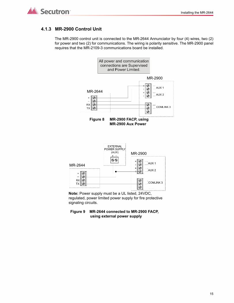
4.1.3 MR-2900 Control Unit
The MR-2900 control unit is connected to the MR-2644 Annunciator by four (4) wires, two (2)for power and two (2) for communications. The wiring is polarity sensitive. The MR-2900 panelrequires that the MR-2109-3 communications board be installed.
MR-2644
MR-2900
Figure 8 MR-2900 FACP, using MR-2900 Aux Power
MR-2644
MR-2900
Figure 9 MR-2644 connected to MR-2900 FACP, using external power supply
Note: Power supply must be a UL listed, 24VDC, regulated, power limited power supply for fire protective signaling circuits.
16
Installing the MR-2644
4.2 Connecting Multiple MR-2644 Annunciators
Up to eight (8) MR-2644 remote annunciators can be connected to a single Fire Alarm ControlPanel.
If this is required, it can be done using either "daisy chain" or "home run" methods. Refer to thewiring specifications in this manual for the guidelines regarding maximum wire length.
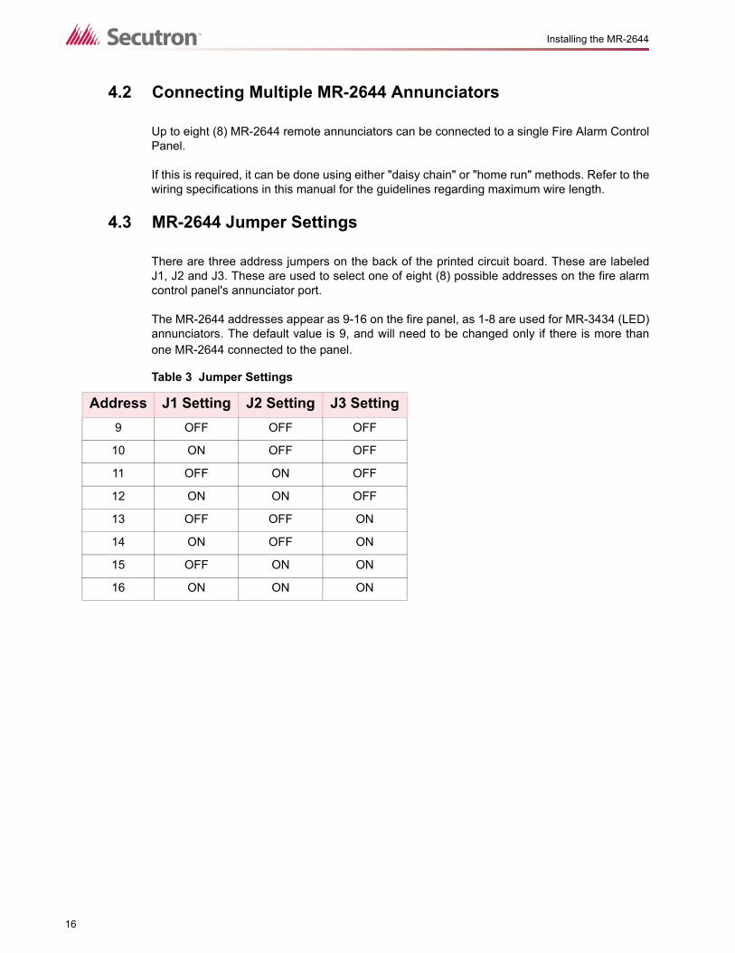
4.3 MR-2644 Jumper Settings
There are three address jumpers on the back of the printed circuit board. These are labeledJ1, J2 and J3. These are used to select one of eight (8) possible addresses on the fire alarmcontrol panel's annunciator port.
The MR-2644 addresses appear as 9-16 on the fire panel, as 1-8 are used for MR-3434 (LED)annunciators. The default value is 9, and will need to be changed only if there is more thanone MR-2644 connected to the panel.
Table 3 Jumper Settings
Address J1 Setting J2 Setting J3 Setting9 OFF OFF OFF
10 ON OFF OFF
11 OFF ON OFF
12 ON ON OFF
13 OFF OFF ON
14 ON OFF ON
15 OFF ON ON
16 ON ON ON

17
Mounting
5.0 Mounting5.1 Flush Mounting
Please refer to Section 1.3 for further details regarding the available ordering options.
1. Choose a suitable place for mounting, observing all applicable codes and standards.
2. Ensure that all power sources to the Fire Alarm Control Panel are disconnected. (This includes both AC and battery power.)
3. Install a standard 5-gang electrical backbox and run all applicable wiring in accordance with the wiring specifications described in this manual.
4. Set the addressing jumpers corresponding to the system programming and layout.
5. Connect the field wiring to the terminals on the back of the assembly.
6. Mount the assembly to the 5-gang electrical backbox using the provided screws.
7. Mount the trim-ring using the four painted screws included in the Hardware Pack.
5.2 Surface Mounting
These instructions apply specifically to the MR-2644 when used in conjunction with the MR-3644-SMR surface mount backbox. Please refer to Section 1.3 for further details regarding theavailable ordering options.
1. Choose a suitable place for mounting, observing all applicable codes and standards.
2. Ensure that all power sources to the Fire Alarm Control Panel are disconnected. (This includes both AC and battery power.)
3. Install the surface-mount backbox using the four mounting holes along with the included hardware. Feed all applicable wiring through the most convenient knockout in accordance with the wiring specifications described in this manual.
4. Set the addressing jumpers corresponding to the system programming and layout.
5. Connect the field wiring to the terminals on the back of the assembly.
6. Mount the assembly to the surface-mount backbox using the provided screws.
7. Mount the trim-ring using the four painted screws included in the Hardware Pack.
18
Operating the MR-2644
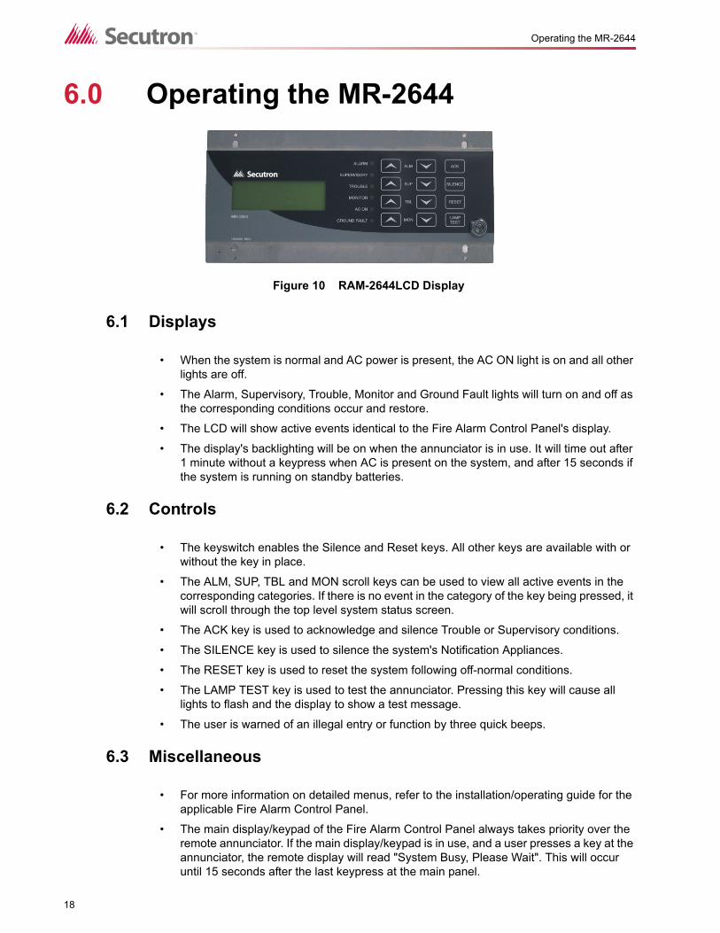
6.0 Operating the MR-2644
6.1 Displays
• When the system is normal and AC power is present, the AC ON light is on and all other lights are off.
• The Alarm, Supervisory, Trouble, Monitor and Ground Fault lights will turn on and off as the corresponding conditions occur and restore.
• The LCD will show active events identical to the Fire Alarm Control Panel's display.
• The display's backlighting will be on when the annunciator is in use. It will time out after 1 minute without a keypress when AC is present on the system, and after 15 seconds if the system is running on standby batteries.
6.2 Controls
• The keyswitch enables the Silence and Reset keys. All other keys are available with or without the key in place.
• The ALM, SUP, TBL and MON scroll keys can be used to view all active events in the corresponding categories. If there is no event in the category of the key being pressed, it will scroll through the top level system status screen.
• The ACK key is used to acknowledge and silence Trouble or Supervisory conditions.
• The SILENCE key is used to silence the system's Notification Appliances.
• The RESET key is used to reset the system following off-normal conditions.
• The LAMP TEST key is used to test the annunciator. Pressing this key will cause all lights to flash and the display to show a test message.
• The user is warned of an illegal entry or function by three quick beeps.
6.3 Miscellaneous
• For more information on detailed menus, refer to the installation/operating guide for the applicable Fire Alarm Control Panel.
• The main display/keypad of the Fire Alarm Control Panel always takes priority over the remote annunciator. If the main display/keypad is in use, and a user presses a key at the annunciator, the remote display will read "System Busy, Please Wait". This will occur until 15 seconds after the last keypress at the main panel.
Figure 10 RAM-2644LCD Display

19
Warranty and Warning Information
7.0 Warranty and Warning Information7.1 Warning Please Read Carefully
7.2 Note to Installers
This warning contains vital information. As the only individual in contact with system users, it isyour responsibility to bring each item in this warning to the attention of the users of thissystem. Failure to properly inform system end-users of the circumstances in which the systemmight fail may result in over-reliance upon the system. As a result, it is imperative that youproperly inform each customer for whom you install the system of the possible forms of failure.
7.3 System Failures
This system has been carefully designed to be as effective as possible. There arecircumstances, such as fire or other types of emergencies where it may not provide protection.Alarm systems of any type may be compromised deliberately or may fail to operate asexpected for a variety of reasons. Some reasons for system failure include:
7.3.1 Inadequate Installation
A Fire Alarm system must be installed in accordance with all the applicable codes andstandards in order to provide adequate protection. An inspection and approval of the initialinstallation, or, after any changes to the system, must be conducted by the Local AuthorityHaving Jurisdiction. Such inspections ensure installation has been carried out properly.
7.3.2 Power Failure
Control units, smoke detectors and many other connected devices require an adequate powersupply for proper operation. If the system or any device connected to the system operatesfrom batteries, it is possible for the batteries to fail. Even if the batteries have not failed, theymust be fully charged, in good condition and installed correctly. If a device operates only byAC power, any interruption, however brief, will render that device inoperative while it does nothave power. Power interruptions of any length are often accompanied by voltage fluctuationswhich may damage electronic equipment such as a fire alarm system. After a powerinterruption has occurred, immediately conduct a complete system test to ensure that thesystem operates as intended.
7.3.3 Failure of Replaceable Batteries
Systems with wireless transmitters have been designed to provide several years of battery lifeunder normal conditions. The expected battery life is a function of the device environment,usage and type. Ambient conditions such as high humidity, high or low temperatures, or largetemperature fluctuations may reduce the expected battery life. While each transmitting devicehas a low battery monitor which identifies when the batteries need to be replaced, this monitor
Note to End UsersThis equipment is subject to terms and conditions of sale as followsi
20
Warranty and Warning Information
may fail to operate as expected. Regular testing and maintenance will keep the system ingood operating condition.
7.3.4 Compromise of Radio Frequency (Wireless) Devices
Signals may not reach the receiver under all circumstances which could include metal objectsplaced on or near the radio path or deliberate jamming or other inadvertent radio signalinterference.
7.3.5 System Users
A user may not be able to operate a panic or emergency switch possibly due to permanent ortemporary physical disability, inability to reach the device in time, or unfamiliarity with thecorrect operation. It is important that all system users be trained in the correct operation of thealarm system and that they know how to respond when the system indicates an alarm.
7.3.6 Automatic Alarm Initiating Devices
Smoke detectors, heat detectors and other alarm initiating devices that are a part of thissystem may not properly detect a fire condition or signal the control panel to alert occupants ofa fire condition for a number of reasons, such as: the smoke detectors or heat detector mayhave been improperly installed or positioned; smoke or heat may not be able to reach thealarm initiating device, such as when the fire is in a chimney, walls or roofs, or on the otherside of closed doors; and, smoke and heat detectors may not detect smoke or heat from fireson another level of the residence or building.
7.3.7 Software
Most Secutron products contain software. With respect to those products, Secutron does notwarranty that the operation of the software will be uninterrupted or error-free or that thesoftware will meet any other standard of performance, or that the functions or performance ofthe software will meet the user’s requirements. Secutron shall not be liable for any delays,breakdowns, interruptions, loss, destruction, alteration or other problems in the use of aproduct arising our of, or caused by, the software.
Every fire is different in the amount and rate at which smoke and heat are generated. Smokedetectors cannot sense all types of fires equally well. Smoke detectors may not provide timelywarning of fires caused by carelessness or safety hazards such as smoking in bed, violentexplosions, escaping gas, improper storage of flammable materials, overloaded electricalcircuits, children playing with matches or arson.
Even if the smoke detector or heat detector operates as intended, there may be circumstanceswhen there is insufficient warning to allow all occupants to escape in time to avoid injury ordeath.
7.3.8 Alarm Notification Appliances
Alarm Notification Appliances such as sirens, bells, horns, or strobes may not warn people orwaken someone sleeping if there is an intervening wall or door. If notification appliances arelocated on a different level of the residence or premise, then it is less likely that the occupantswill be alerted or awakened. Audible notification appliances may be interfered with by othernoise sources such as stereos, radios, televisions, air conditioners or other appliances, orpassing traffic. Audible notification appliances, however loud, may not be heard by a hearing-impaired person.
21
Warranty and Warning Information
7.3.9 Telephone Lines
If telephone lines are used to transmit alarms, they may be out of service or busy for certainperiods of time. Also the telephone lines may be compromised by such things as criminaltampering, local construction, storms or earthquakes.
7.3.10 Insufficient Time
There may be circumstances when the system will operate as intended, yet the occupants willnot be protected from the emergency due to their inability to respond to the warnings in atimely manner. If the system is monitored, the response may not occur in time enough toprotect the occupants or their belongings.
7.3.11 Component Failure
Although every effort has been made to make this system as reliable as possible, the systemmay fail to function as intended due to the failure of a component.
7.3.12 Inadequate Testing
Most problems that would prevent an alarm system from operating as intended can bediscovered by regular testing and maintenance. The complete system should be tested asrequired by national standards and the Local Authority Having Jurisdiction and immediatelyafter a fire, storm, earthquake, accident, or any kind of construction activity inside or outsidethe premises. The testing should include all sensing devices, keypads, consoles, alarmindicating devices and any other operational devices that are part of the system.
7.3.13 Security and Insurance
Regardless of its capabilities, an alarm system is not a substitute for property or life insurance.An alarm system also is not a substitute for property owners, renters, or other occupants to actprudently to prevent or minimize the harmful effects of an emergency situation.
IMPORTANT NOTE: End-users of the system must take care to ensure that the system,batteries, telephone lines, etc. are tested and examined on a regular basis to ensure theminimization of system failure.
7.4 Limited Warranty
Secutron Inc. together with its subsidiaries and affiliates (collectively, the “Mircom Group ofCompanies”) warrants the original purchaser that for a period of three years from the date ofshipment, the product shall be free of defects in materials and workmanship under normal use.During the warranty period, Secutron shall, at its option, repair or replace any defectiveproduct upon return of the product to its factory, at no charge for labor and materials. Anyreplacement and/or repaired parts are warranted for the remainder of the original warranty orninety (90) days, whichever is longer. The original owner must promptly notify Secutron inwriting that there is defect in material or workmanship, such written notice to be received in allevents prior to expiration of the warranty period.
7.4.1 International Warranty
The warranty for international customers is the same as for any customer within Canada andthe United States, with the exception that Secutron shall not be responsible for any customsfees, taxes, or VAT that may be due.
22
Warranty and Warning Information
7.4.2 Conditions to Void Warranty
This warranty applies only to defects in parts and workmanship relating to normal use. It doesnot cover:
• damage incurred in shipping or handling;
• damage caused by disaster such as fire, flood, wind, earthquake or lightning;
• damage due to causes beyond the control of Secutron such as excessive voltage, mechanical shock or water damage;
• damage caused by unauthorized attachment, alterations, modifications or foreign objects;
• damage caused by peripherals (unless such peripherals were supplied by Secutron);
• defects caused by failure to provide a suitable installation environment for the products;
• damage caused by use of the products for purposes other than those for which it was designed;
• damage from improper maintenance;
• damage arising out of any other abuse, mishandling or improper application of the products.
7.5 Warranty Procedure
To obtain service under this warranty, please return the item(s) in question to the point ofpurchase. All authorized distributors and dealers have a warranty program. Anyone returninggoods to Secutron must first obtain an authorization number. Secutron will not accept anyshipment whatsoever for which prior authorization has not been obtained. NOTE: Unlessspecific pre-authorization in writing is obtained from Secutron management, no credits will beissued for custom fabricated products or parts or for complete fire alarm system. Secutron willat its sole option, repair or replace parts under warranty. Advance replacements for such itemsmust be purchased.
Note: Secutron’s liability for failure to repair the product under this warranty after a reasonablenumber of attempts will be limited to a replacement of the product, as the exclusive remedy forbreach of warranty.
7.6 Disclaimer of Warranties
This warranty contains the entire warranty and shall be in lieu of any and all other warranties,whether expressed or implied (including all implied warranties of merchantability or fitness fora particular purpose) And of all other obligations or liabilities on the part of Secutron neitherassumes nor authorizes any other person purporting to act on its behalf to modify or to changethis warranty, nor to assume for it any other warranty or liability concerning this product.
This disclaimer of warranties and limited warranty are governed by the laws of the province ofOntario, Canada.
7.7 Out of Warranty Repairs
Secutron will at its option repair or replace out-of-warranty products which are returned to itsfactory according to the following conditions. Anyone returning goods to Secutron must first
23
Warranty and Warning Information
obtain an authorization number. Secutron will not accept any shipment whatsoever for whichprior authorization has not been obtained.
Products which Secutron determines to be repairable will be repaired and returned. A set feewhich Secutron has predetermined and which may be revised from time to time, will becharged for each unit repaired.
Products which Secutron determines not to be repairable will be replaced by the nearestequivalent product available at that time. The current market price of the replacement productwill be charged for each replacement unit.
The preceding information is accurate as of the date of publishing and is subject to change or revision without prior notice at the sole discretion of the Company.
WARNING: Secutron recommends that the entire system be completely tested on a regular basis. However, despite frequent testing, and due to, but not limited to, criminal tampering or electrical disruption, it is possible for this product to fail to perform as expected.
NOTE: Under no circumstances shall Secutron be liable for any special, incidental, or consequential damages based upon breach of warranty, breach of contract, negligence, strict liability, or any other legal theory. Such damages include, but are not limited to, loss of profits, loss of the product or any associated equipment, cost of capital, cost of substitute or replacement equipment, facilities or services, down time, purchaser’s time, the claims of third parties, including customers, and injury to property.
SECUTRON MAKES NO WARRANTY OF MERCHANTABILITY OR FITNESS FOR A PARTICULAR PURPOSE WITH RESPECT TO ITS GOODS DELIVERED, NOR IS THERE ANY OTHER WARRANTY, EXPRESSED OR IMPLIED, EXCEPT FOR THE WARRANTY CONTAINED HEREIN.

© 2011 Secutron Inc.
No part of this publication may be reproduced, transmitted,transcribed, stored in a retrieval system, or translated intoany language or computer language, in any form by anymeans electronic, magnetic, optical, chemical, manual, orotherwise without the prior consent of Secutron.
Canada25 Interchange WayVaughan, ON L4K 5W3Tel: (888) SECUTRON (888) 732-8876Fax: (905) 660-4113
U.S.A4575 Witmer Industrial EstatesNiagara Falls, New York 14305Tel: (888) SECUTRON (888) 732-8876Fax: (905) 660-4113
Technical SupportNorth America OnlyTel: (888) Mircom5 (888) 647-2665InternationalTel: (905) 647-2665