MPX Magnetostrictive Level Sensors User Manual R Doc #9003761 Rev F, 06/2017 MPX Magnetostrictive...
42
APG R Doc #9003761 Rev F, 06/2017 MPX Magnetostrictive Level Sensors User Manual For The MPX-E, MPX-E Chemical, and MPX-R
-
Upload
duongkhanh -
Category
Documents
-
view
262 -
download
1
Transcript of MPX Magnetostrictive Level Sensors User Manual R Doc #9003761 Rev F, 06/2017 MPX Magnetostrictive...

APGR
Doc #9003761Rev F, 06/2017
MPX Magnetostrictive Level SensorsUser Manual
For The MPX-E, MPX-E Chemical, and MPX-R
ii Tel: 1/888/525-7300 • Fax: 1/435/753-7490 • www.apgsensors.com • [email protected]
Table of Contents
Introduction ................................................................................................................ iii
Warranty and Warranty Restrictions .................................................................... iv
Chapter 1: Specifications and Options..................................................................... 1 Dimensions ....................................................................................................................................1-3 Specifications ................................................................................................................................... 4 Model Number Configurator .......................................................................................................5-7 Electrical Connections and System Wiring Diagrams ........................................................ 8-9
Chapter 2: Installation and Removal Procedures and Notes ............................ 10 Tools Needed ................................................................................................................................... 10 Physical Installation Notes ......................................................................................................... 10 Physical Installation Instructions ..............................................................................................11 Electrical Installation ....................................................................................................................11 Removal Instructions ................................................................................................................... 12
Chapter 3: Programming .......................................................................................... 12 Modbus Programming .................................................................................................................. 12 Modbus Programming with RST-6001 and APG Modbus Software .................................... 13 4-20 mA Programming with RST-4100 and APG Modbus Software .................................... 13 Modbus Register Lists For MPX-E/R4 ..................................................................................13-14 MPX-E/R4 Modbus Sensor Parameters ................................................................................ 15-19 APG Modbus Register Lists for MPX-E/R2 and MPX-E/R3 ............................................. 19-20 MPX-E/R2 and MPX-E/R3 APG Modbus Sensor Parameters ...........................................21-25 MPX-E/R Modbus Application Type Parameters ..............................................................26-30
Chapter 4: Maintenance ........................................................................................... 31 General Care .................................................................................................................................... 31 Repair and Returns ........................................................................................................................ 31
Chapter 5: Hazardous Location Installation and Certification .........................32 Hazardous Location and Non-Incendive Wiring Diagram .................................................... 32 CSA Certificate of Compliance .............................................................................................. 33-36
iiiTel: 1/888/525-7300 • Fax: 1/435/753-7490 • www.apgsensors.com • [email protected]
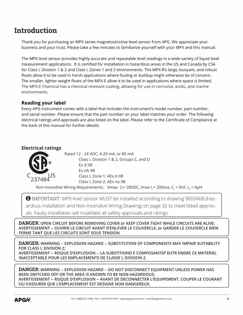
IntroductionThank you for purchasing an MPX series magnetostrictive level sensor from APG. We appreciate your business and your trust. Please take a few minutes to familiarize yourself with your MPX and this manual.
The MPX level sensor provides highly accurate and repeatable level readings in a wide variety of liquid level measurement applications. It is certified for installation in hazardous areas in the US and Canada by CSA for Class I, Division 1 & 2 and Class I, Zones 1 and 2 environments. The MPX-R’s large, buoyant, and robust floats allow it to be used in harsh applications where fouling or buildup might otherwise be of concern. The smaller, lighter weight floats of the MPX-E allow it to be used in applications where space is limited. The MPX-E Chemical has a chemical resistant coating, allowing for use in corrosive, acidic, and marine environments.
Reading your labelEvery APG instrument comes with a label that includes the instrument’s model number, part number, and serial number. Please ensure that the part number on your label matches your order. The following electrical ratings and approvals are also listed on the label. Please refer to the Certificate of Compliance at the back of this manual for further details.
Electrical ratings Rated 12 - 24 VDC, 4-20 mA, or 80 mA
Class I, Division 1 & 2, Groups C, and D Ex d IIB Ex nA IIB Class I, Zone 1; AEx d IIB Class I, Zone 2; AEx na IIB Non-Incendive Wiring Requirements: Vmax Ui= 28VDC, Imax Ii = 200ma, Ci = 0nF, Li = 0μH
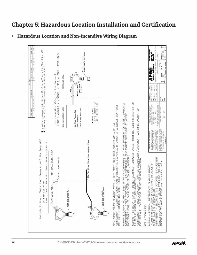
IMPORTANT: MPX level sensor MUST be installed according to drawing 9003468 (Haz-ardous Installation and Non-Incendive Wiring Drawing) on page 32 to meet listed approv-als. Faulty installation will invalidate all safety approvals and ratings.
DANGER: WARNING -- EXPLOSION HAZARD -- SUBSTITUTION OF COMPONENTS MAY IMPAIR SUITABILITY FOR CLASS I, DIVISION 2;AVERTISSEMENT -- RISQUE D’EXPLOSION -- LA SUBSTITIOND E COMPOSANTSP EUTR ENDRE CE MATERIEL INACCEPTABLE POUR LES EMPLACEMENTS DE CLASSE I, DIVISION 2.
DANGER: WARNING -- EXPLOSION HAZARD -- DO NOT DISCONNECT EQUIPMENT UNLESS POWER HAS BEEN SWITCHED OFF OR THE AREA IS KNOWN TO BE NON-HAZARDOUS;AVERTISSEMENT -- RISQUE D’EXPLOSION -- AVANT DE DECONNECTER L’EQUIPEMENT, COUPER LE COURANT OU S’ASSURER QUE L’EMPLACEMENT EST DESIGNE NON DANGEREUX.
DANGER: OPEN CIRCUIT BEFORE REMOVING COVER or KEEP COVER TIGHT WHILE CIRCUITS ARE ALIVE;AVERTISSEMENT -- OUVRIR LE CIRCUIT AVANT D’ENLEVER LE COUVERCLE, or GARDER LE COUVERCLE BIEN FERME TANT QUE LES CIRCUITS SONT SOUS TENSION.
USC237484
iv Tel: 1/888/525-7300 • Fax: 1/435/753-7490 • www.apgsensors.com • [email protected]
Warranty and Warranty RestrictionsThis product is covered by APG’s waranty to be free from defects in material and workmanship under normal use and service of the product for 24 months. For a full explanation of our Warranty, please visit https://www.apgsensors.com/about-us/terms-conditions. Contact Technical Support to recieve a Return Material Authorization before shipping your product back.
Scan the QR code below to read the full explanation of our Warranty on your tablet or smartphone.
1Tel: 1/888/525-7300 • Fax: 1/435/753-7490 • www.apgsensors.com • [email protected]
Chapter 1: Specifications and Options
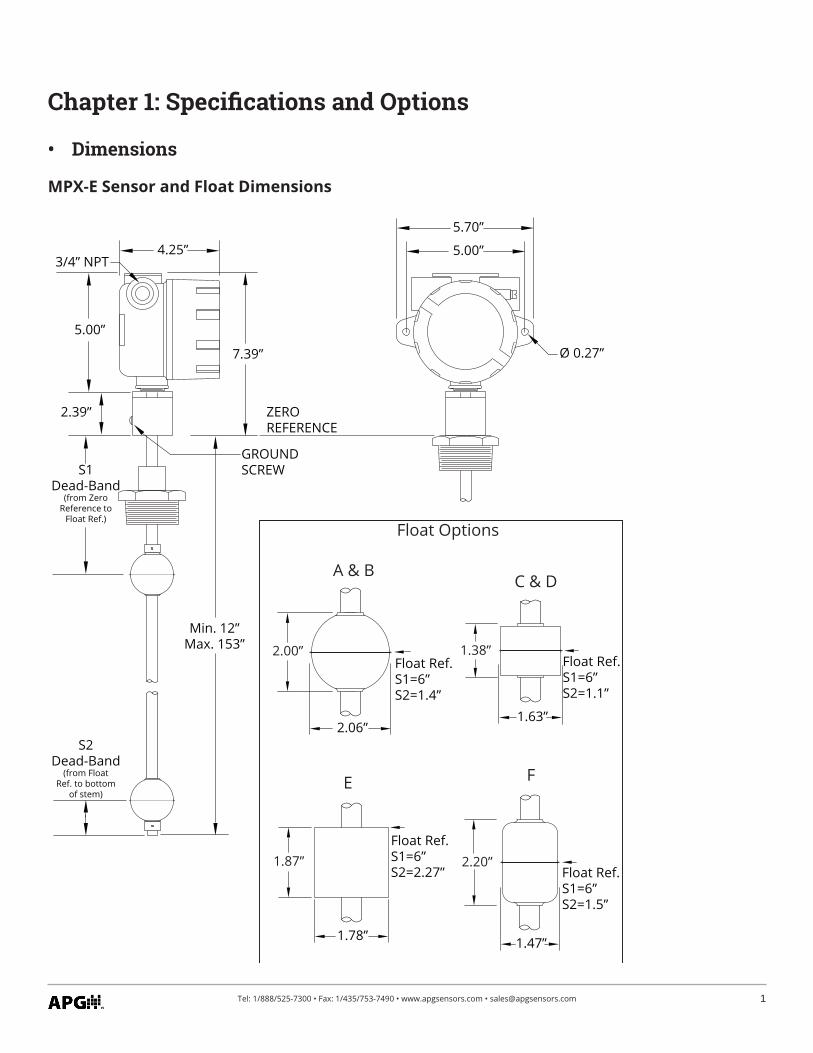
MPX-E Sensor and Float Dimensions
• Dimensions
4.25”
7.39”
5.00”
5.70”
Ø 0.27”
Float Options
2.00”
2.06”
A & B
Float Ref.S1=6”S2=1.4”
1.38”
1.63”
C & D
2.20”
1.47”
F
1.87”
1.78”
E
S1Dead-Band
(from ZeroReference to
Float Ref.)
S2Dead-Band
(from FloatRef. to bottom
of stem)
3/4” NPT
2.39”
5.00”
ZEROREFERENCE
Min. 12”Max. 153”
GROUND SCREW
Float Ref.S1=6”S2=1.1”
Float Ref.S1=6”S2=2.27” Float Ref.
S1=6”S2=1.5”
2 Tel: 1/888/525-7300 • Fax: 1/435/753-7490 • www.apgsensors.com • [email protected]
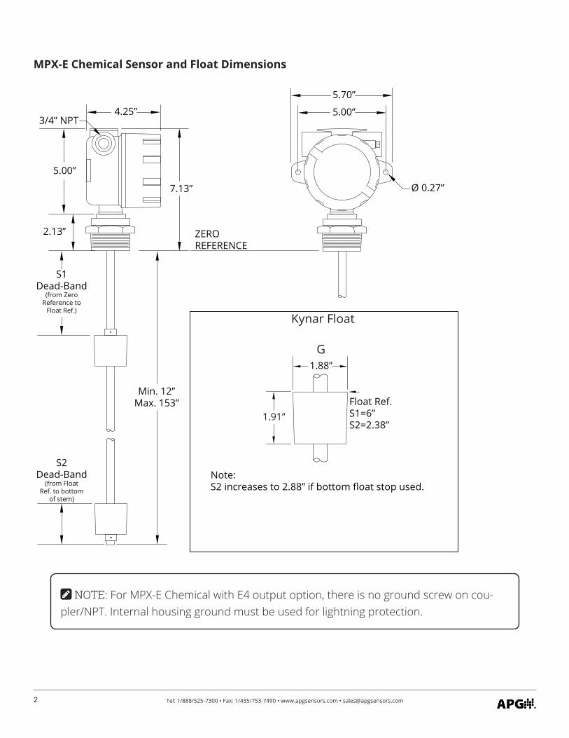
MPX-E Chemical Sensor and Float Dimensions
4.25”
7.13”
5.00”
5.70”
Ø 0.27”
Kynar Float
S1Dead-Band
(from ZeroReference to
Float Ref.)
S2Dead-Band
(from FloatRef. to bottom
of stem)
3/4” NPT
2.13”
5.00”
ZEROREFERENCE
Min. 12”Max. 153”
1.91”
1.88”G
Float Ref.S1=6”S2=2.38”
Note:S2 increases to 2.88” if bottom float stop used.
NOTE: For MPX-E Chemical with E4 output option, there is no ground screw on cou-pler/NPT. Internal housing ground must be used for lightning protection.
3Tel: 1/888/525-7300 • Fax: 1/435/753-7490 • www.apgsensors.com • [email protected]
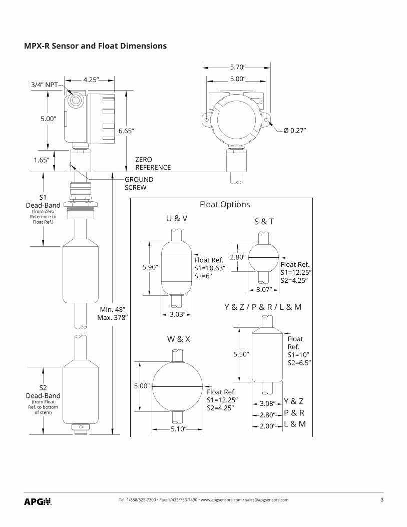
MPX-R Sensor and Float Dimensions
5.00”
5.70”
Ø 0.27”
5.00”
5.10”
5.90”
3.03”
5.50”
3.08”
2.80”
3.07”
Float Ref.S1=10.63”S2=6”
Float Ref.S1=12.25”S2=4.25”
Float Ref.S1=12.25”S2=4.25”
Float Options
Y & Z / P & R / L & M
W & X
S & TU & V
4.25”
6.65”
S1Dead-Band
(from ZeroReference to
Float Ref.)
S2Dead-Band
(from FloatRef. to bottom
of stem)
FloatRef.S1=10”S2=6.5”
3/4” NPT
1.65”
5.00”
2.80”
2.00”
Y & ZP & RL & M
Min. 48”Max. 378”
ZEROREFERENCE
GROUND SCREW
4 Tel: 1/888/525-7300 • Fax: 1/435/753-7490 • www.apgsensors.com • [email protected]
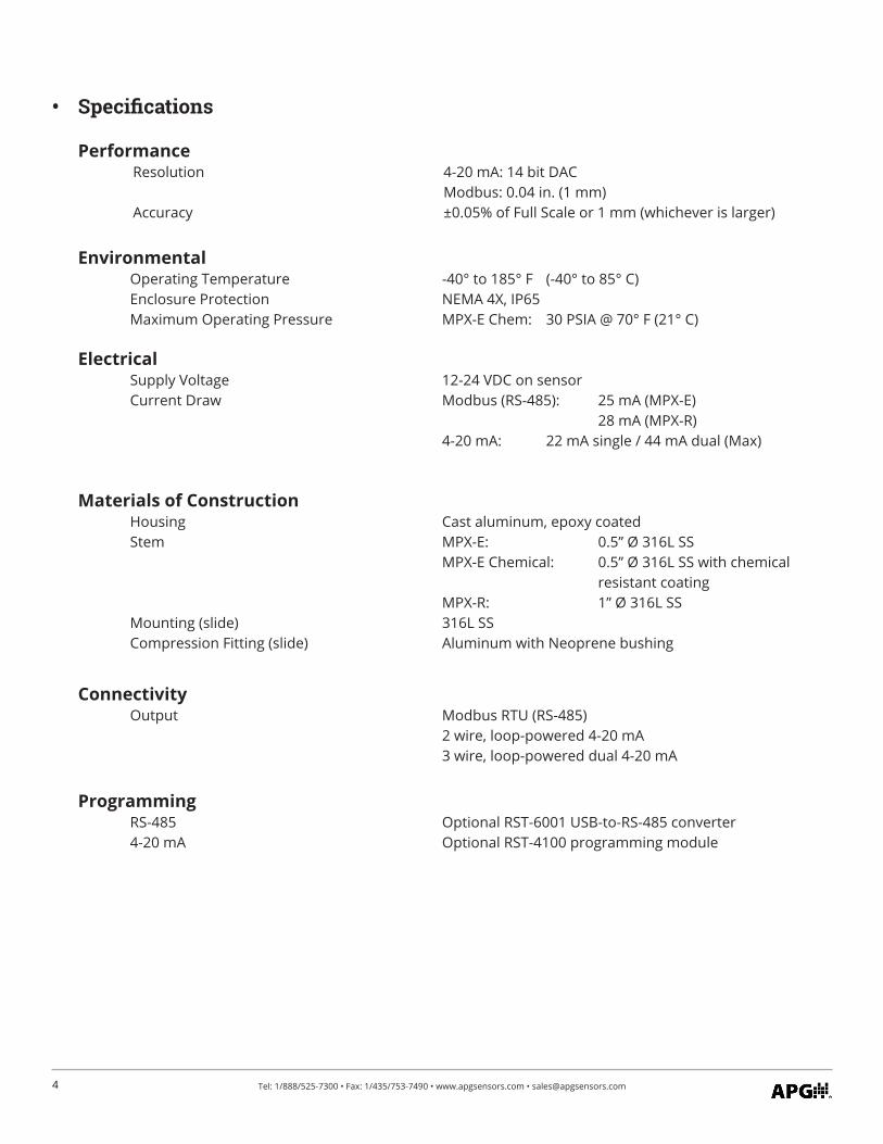
Performance Resolution 4-20 mA: 14 bit DAC Modbus: 0.04 in. (1 mm) Accuracy ±0.05% of Full Scale or 1 mm (whichever is larger)
Environmental Operating Temperature -40° to 185° F (-40° to 85° C) Enclosure Protection NEMA 4X, IP65 Maximum Operating Pressure MPX-E Chem: 30 PSIA @ 70° F (21° C)
Electrical Supply Voltage 12-24 VDC on sensor Current Draw Modbus (RS-485): 25 mA (MPX-E) 28 mA (MPX-R) 4-20 mA: 22 mA single / 44 mA dual (Max)
Materials of Construction Housing Cast aluminum, epoxy coated Stem MPX-E: 0.5” Ø 316L SS
MPX-E Chemical: 0.5” Ø 316L SS with chemical resistant coating
MPX-R: 1” Ø 316L SS Mounting (slide) 316L SS Compression Fitting (slide) Aluminum with Neoprene bushing
Connectivity Output Modbus RTU (RS-485) 2 wire, loop-powered 4-20 mA 3 wire, loop-powered dual 4-20 mA
Programming RS-485 Optional RST-6001 USB-to-RS-485 converter 4-20 mA Optional RST-4100 programming module
• Specifications
5Tel: 1/888/525-7300 • Fax: 1/435/753-7490 • www.apgsensors.com • [email protected]
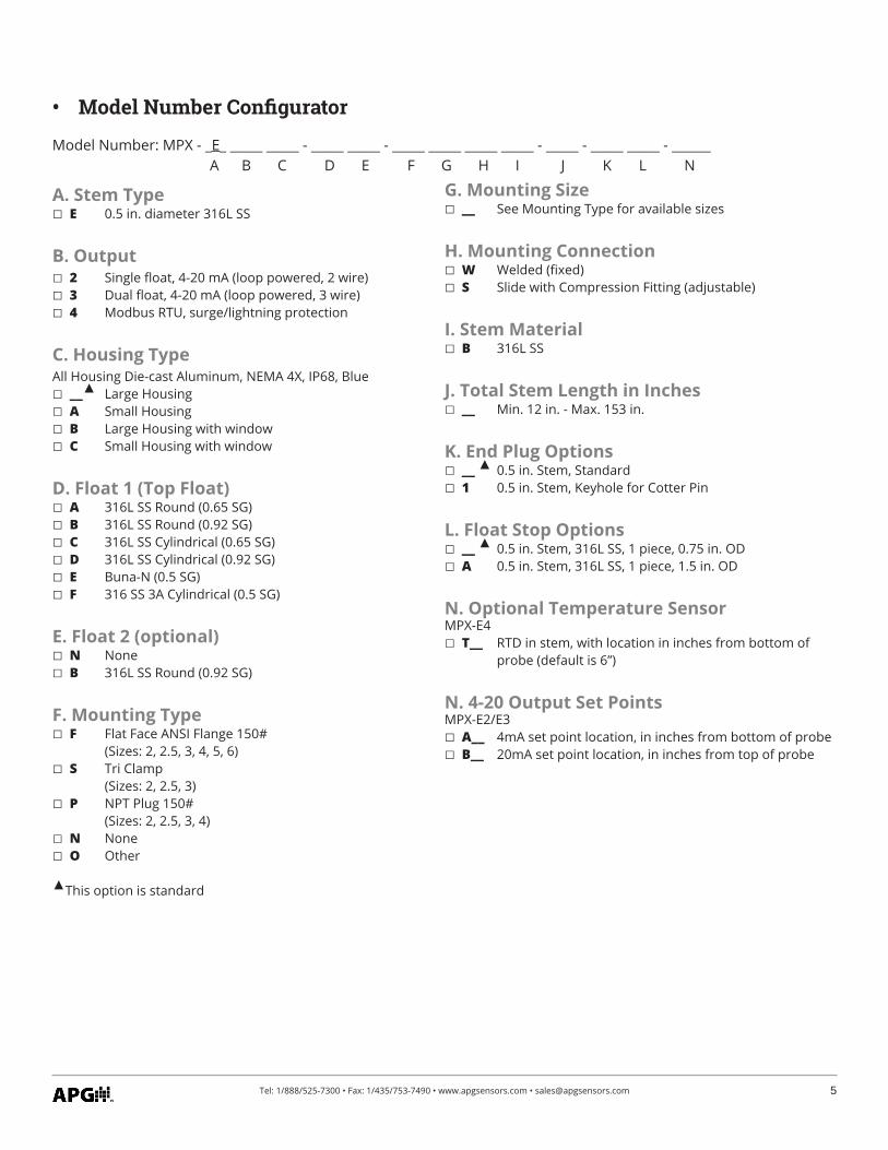
• Model Number Configurator
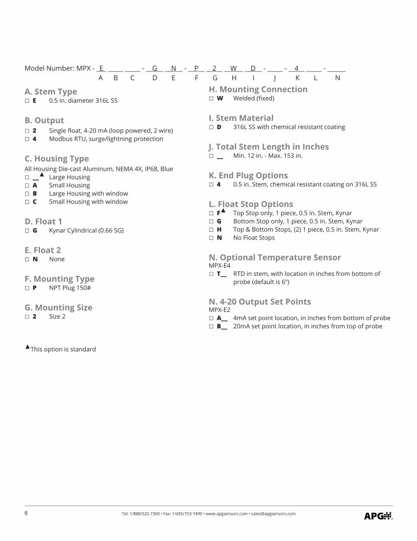
Model Number: MPX - _E_ _____ _____ - _____ _____ - _____ _____ _____ _____ - _____ - _____ _____ - ______ A B C D E F G H I J K L N
A. Stem Type E 0.5 in. diameter 316L SS
B. Output 2 Single float, 4-20 mA (loop powered, 2 wire) 3 Dual float, 4-20 mA (loop powered, 3 wire) 4 Modbus RTU, surge/lightning protection
C. Housing TypeAll Housing Die-cast Aluminum, NEMA 4X, IP68, Blue __ Large Housing A Small Housing B Large Housing with window C Small Housing with window
D. Float 1 (Top Float) A 316L SS Round (0.65 SG) B 316L SS Round (0.92 SG) C 316L SS Cylindrical (0.65 SG) D 316L SS Cylindrical (0.92 SG) E Buna-N (0.5 SG) F 316 SS 3A Cylindrical (0.5 SG)
E. Float 2 (optional) N None B 316L SS Round (0.92 SG)
F. Mounting Type F Flat Face ANSI Flange 150# (Sizes: 2, 2.5, 3, 4, 5, 6) S Tri Clamp (Sizes: 2, 2.5, 3) P NPT Plug 150# (Sizes: 2, 2.5, 3, 4) N None O Other
This option is standard
G. Mounting Size __ See Mounting Type for available sizes
H. Mounting Connection W Welded (fixed) S Slide with Compression Fitting (adjustable)
I. Stem Material B 316L SS
J. Total Stem Length in Inches __ Min. 12 in. - Max. 153 in.
K. End Plug Options __ 0.5 in. Stem, Standard 1 0.5 in. Stem, Keyhole for Cotter Pin
L. Float Stop Options __ 0.5 in. Stem, 316L SS, 1 piece, 0.75 in. OD A 0.5 in. Stem, 316L SS, 1 piece, 1.5 in. OD
N. Optional Temperature SensorMPX-E4 T__ RTD in stem, with location in inches from bottom of
probe (default is 6”)
N. 4-20 Output Set PointsMPX-E2/E3 A__ 4mA set point location, in inches from bottom of probe B__ 20mA set point location, in inches from top of probe
6 Tel: 1/888/525-7300 • Fax: 1/435/753-7490 • www.apgsensors.com • [email protected]
Model Number: MPX - _E_ _____ _____ - __G__ __N__ - __P__ __2__ __W__ __D__ - _____ - __4__ _____ - ______ A B C D E F G H I J K L N
A. Stem Type E 0.5 in. diameter 316L SS
B. Output 2 Single float, 4-20 mA (loop powered, 2 wire) 4 Modbus RTU, surge/lightning protection
C. Housing TypeAll Housing Die-cast Aluminum, NEMA 4X, IP68, Blue __ Large Housing A Small Housing B Large Housing with window C Small Housing with window
D. Float 1 G Kynar Cylindrical (0.66 SG)
E. Float 2 N None
F. Mounting Type P NPT Plug 150#
G. Mounting Size 2 Size 2
This option is standard
H. Mounting Connection W Welded (fixed)
I. Stem Material D 316L SS with chemical resistant coating
J. Total Stem Length in Inches __ Min. 12 in. - Max. 153 in.
K. End Plug Options 4 0.5 in. Stem, chemical resistant coating on 316L SS
L. Float Stop Options F Top Stop only, 1 piece, 0.5 in. Stem, Kynar G Bottom Stop only, 1 piece, 0.5 in. Stem, Kynar H Top & Bottom Stops, (2) 1 piece, 0.5 in. Stem, Kynar N No Float Stops
N. Optional Temperature SensorMPX-E4 T__ RTD in stem, with location in inches from bottom of
probe (default is 6”)
N. 4-20 Output Set PointsMPX-E2 A__ 4mA set point location, in inches from bottom of probe B__ 20mA set point location, in inches from top of probe
7Tel: 1/888/525-7300 • Fax: 1/435/753-7490 • www.apgsensors.com • [email protected]
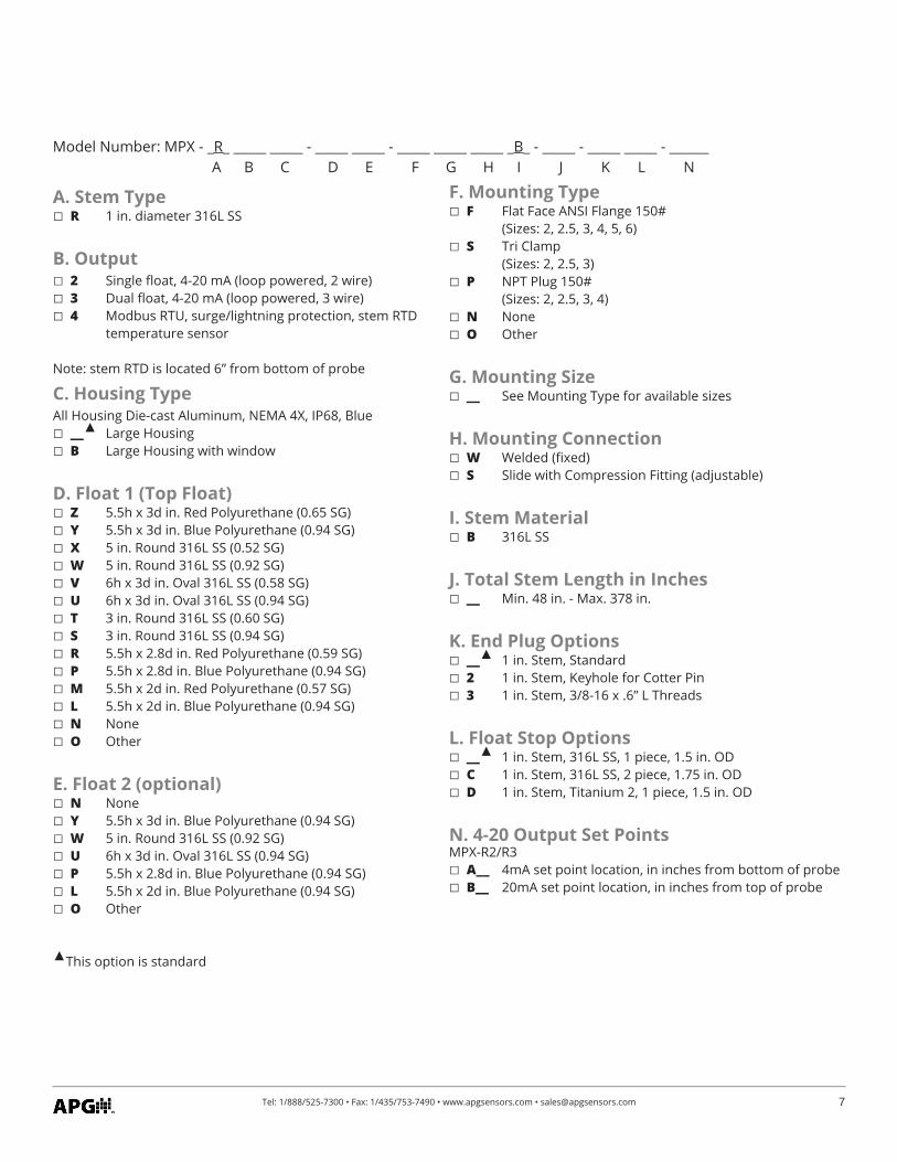
Model Number: MPX - _R_ _____ _____ - _____ _____ - _____ _____ _____ _B_ - _____ - _____ _____ - ______ A B C D E F G H I J K L N
A. Stem Type R 1 in. diameter 316L SS
B. Output 2 Single float, 4-20 mA (loop powered, 2 wire) 3 Dual float, 4-20 mA (loop powered, 3 wire) 4 Modbus RTU, surge/lightning protection, stem RTD
temperature sensor
Note: stem RTD is located 6” from bottom of probe
C. Housing TypeAll Housing Die-cast Aluminum, NEMA 4X, IP68, Blue __ Large Housing B Large Housing with window
D. Float 1 (Top Float) Z 5.5h x 3d in. Red Polyurethane (0.65 SG) Y 5.5h x 3d in. Blue Polyurethane (0.94 SG) X 5 in. Round 316L SS (0.52 SG) W 5 in. Round 316L SS (0.92 SG) V 6h x 3d in. Oval 316L SS (0.58 SG) U 6h x 3d in. Oval 316L SS (0.94 SG) T 3 in. Round 316L SS (0.60 SG) S 3 in. Round 316L SS (0.94 SG) R 5.5h x 2.8d in. Red Polyurethane (0.59 SG) P 5.5h x 2.8d in. Blue Polyurethane (0.94 SG) M 5.5h x 2d in. Red Polyurethane (0.57 SG) L 5.5h x 2d in. Blue Polyurethane (0.94 SG) N None O Other
E. Float 2 (optional) N None Y 5.5h x 3d in. Blue Polyurethane (0.94 SG) W 5 in. Round 316L SS (0.92 SG) U 6h x 3d in. Oval 316L SS (0.94 SG) P 5.5h x 2.8d in. Blue Polyurethane (0.94 SG) L 5.5h x 2d in. Blue Polyurethane (0.94 SG) O Other
This option is standard
F. Mounting Type F Flat Face ANSI Flange 150# (Sizes: 2, 2.5, 3, 4, 5, 6) S Tri Clamp (Sizes: 2, 2.5, 3) P NPT Plug 150# (Sizes: 2, 2.5, 3, 4) N None O Other
G. Mounting Size __ See Mounting Type for available sizes
H. Mounting Connection W Welded (fixed) S Slide with Compression Fitting (adjustable)
I. Stem Material B 316L SS
J. Total Stem Length in Inches __ Min. 48 in. - Max. 378 in.
K. End Plug Options __ 1 in. Stem, Standard 2 1 in. Stem, Keyhole for Cotter Pin 3 1 in. Stem, 3/8-16 x .6” L Threads
L. Float Stop Options __ 1 in. Stem, 316L SS, 1 piece, 1.5 in. OD C 1 in. Stem, 316L SS, 2 piece, 1.75 in. OD D 1 in. Stem, Titanium 2, 1 piece, 1.5 in. OD
N. 4-20 Output Set PointsMPX-R2/R3 A__ 4mA set point location, in inches from bottom of probe B__ 20mA set point location, in inches from top of probe
8 Tel: 1/888/525-7300 • Fax: 1/435/753-7490 • www.apgsensors.com • [email protected]
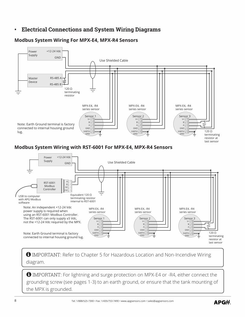
• Electrical Connections and System Wiring Diagrams
IMPORTANT: Refer to Chapter 5 for Hazardous Location and Non-Incendive Wiring diagram.
Modbus System Wiring For MPX-E4, MPX-R4 Sensors
Modbus System Wiring with RST-6001 For MPX-E4, MPX-R4 Sensors
PowerSupply
+12-24 Vdc
GNDUse Shielded Cable
120 Ωterminatingresistor
120 Ωterminatingresistor atlast sensor
V+BA
Sensor 1
GND
V+BA
Sensor 2
GND
V+BA
Sensor 3
GND
MasterDevice
RS-485 A
RS-485 B
MPX-E4, -R4series sensor
MPX-E4, -R4series sensor
MPX-E4, -R4series sensor
EARTHGND
Note: Earth Ground terminal is factoryconnected to internal housing groundlug. EARTH
GNDEARTH
GND
PowerSupply
+12-24 Vdc
GND Use Shielded Cable
Equivalent 120 Ωterminating resistorinternal to RST-6001
120 Ωterminatingresistor atlast sensor
USB to computerwith APG Modbussoftware
RST-6001Modbus
Controller
V+BA
Sensor 1
GND
V+BA
Sensor 2
GND
V+BA
Sensor 3
GND
AB
-5V
MPX-E4, -R4series sensor
+5V
MPX-E4, -R4series sensor
MPX-E4, -R4series sensor
Note: An independent +12-24 Vdcpower supply is required whenusing an RST-6001 Modbus Controller.The RST-6001 can only supply ±5 Vdc,not the +12-24 Vdc required by the MPX.
EARTHGND
EARTHGND
EARTHGND
Note: Earth Ground terminal is factoryconnected to internal housing ground lug.
IMPORTANT: For lightning and surge protection on MPX-E4 or -R4, either connect the grounding screw (see pages 1-3) to an earth ground, or ensure that the tank mounting of the MPX is grounded.
9Tel: 1/888/525-7300 • Fax: 1/435/753-7490 • www.apgsensors.com • [email protected]
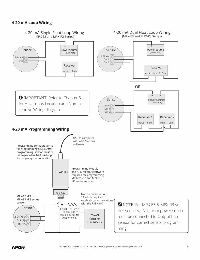
4-20 mA Loop Wiring
12-24 VdcOut (1)
PowerSource
(14- 24 Vdc)
Sensor
Out 24V
RST-4100
Load Resistor(150 Ω to 700 Ω)
Wired in series forprogramming.
+
−
Note: a minimum of 14 Vdc is required toestablish communicationswith the RST-4100
Programming Moduleand APG Modbus softwarerequired for programmingMPX-E2, -R2 and MPX-E3,-R3 series sensors.
USB to computerwith APG Modbussoftware
Out 2
MPX-E2, -R2 orMPX-E3, -R3 seriessensor.
Programming configuration isfor programming ONLY. Afterprogramming, sensor must bereintegrated to 4-20 mA loopfor proper system operation.
12-24 VdcOut 1Out 2
Input 1 Input 2 Com
Receiver
SensorSensor
4-20 mA Dual Float Loop Wiring(MPX-E3 and MPX-R3 Series)
Input Com
Receiver 1
Input Com
Receiver 2
OR
+Power Source
(12-24 Vdc)
−
12-24 VdcOut 1Out 2
Sensor+
Power Source(12-24 Vdc)
−
12-24 VdcOut
4-20 mA Single Float Loop Wiring(MPX-E2 and MPX-R2 Series)
Input Com
Receiver
+Power Source
(12-24 Vdc)
−
4-20 mA Programming Wiring
NOTE: For MPX-E3 & MPX-R3 se-ries sensors, - Vdc from power source must be connected to Output1 on sensor for correct sensor program-ming.
IMPORTANT: Refer to Chapter 5 for Hazardous Location and Non-In-cendive Wiring diagram.
10 Tel: 1/888/525-7300 • Fax: 1/435/753-7490 • www.apgsensors.com • [email protected]
Chapter 2: Installation and Removal Procedures and Notes
You will need the following tools to install your MPX level sensor:• Wrench sized appropriately for MPX mounting• Wrench sized appropriately for conduit connections• Flat-head screwdriver for wire terminals• Channel lock pliers for tightening compression fitting• 3/32” hex Allen wrench for 1-piece MPX-E float stops• 1/8” hex Allen wrench for 1-piece MPX-R float stops• 3/16” hex Allen wrench for 2-piece MPX-R float stops
• Tools Needed
The MPX should be installed in an area--indoors or outdoors--which meets the following conditions:• Ambient temperature between -40°C and 85°C (-40°F to +185°F)• Relative humidity up to 100%• Altitude up to 2000 meters (6560 feet)• IEC-664-1 Conductive Pollution Degree 1 or 2• IEC 61010-1 Measurement Category II• No chemicals corrosive to stainless steel (such as NH3, SO2, Cl2 etc.)• Ample space for maintenance and inspection
Additional care must be taken to ensure:• The probe is located away from strong magnetic fields, such as those produced by motors, transform-
ers, solenoid valves, etc.• The medium is free from metallic substances and other foreign matter.• The probe is not exposed to excessive vibration.• The float(s) fit through the mounting hole. If the float(s) does/do not fit, it/they must be mounted on
the stem from inside the vessel being monitored.• The float(s) is/are oriented properly on the stem (See Figure 2.1). MPX-E floats will be installed by the
factory. MPX-R floats are typically installed by customer.
• Physical Installation Notes
NOTE: For MPX-E Chemical sensors: Chemical resitant coating will scar and expose stainless steel if scraped or abused. Use caution when handling. Always transport in pack-aging to protect probe and coating.
11Tel: 1/888/525-7300 • Fax: 1/435/753-7490 • www.apgsensors.com • [email protected]
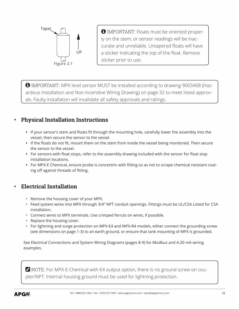
Figure 2.1
UP
Taper IMPORTANT: Floats must be oriented proper-ly on the stem, or sensor readings will be inac-curate and unreliable. Untapered floats will have a sticker indicating the top of the float. Remove sticker prior to use.
IMPORTANT: MPX level sensor MUST be installed according to drawing 9003468 (Haz-ardous Installation and Non-Incendive Wiring Drawing) on page 32 to meet listed approv-als. Faulty installation will invalidate all safety approvals and ratings.
• Remove the housing cover of your MPX.• Feed system wires into MPX through 3/4” NPT conduit openings. Fittings must be UL/CSA Listed for CSA
installation.• Connect wires to MPX terminals. Use crimped ferruls on wires, if possible.• Replace the housing cover.• For lightning and surge protection on MPX-E4 and MPX-R4 models, either connect the grounding screw
(see dimensions on page 1-3) to an earth ground, or ensure that tank mounting of MPX is grounded.
See Electrical Connections and System Wiring Diagrams (pages 8-9) for Modbus and 4-20 mA wiring examples.
• Electrical Installation
• If your sensor’s stem and floats fit through the mounting hole, carefully lower the assembly into the vessel, then secure the sensor to the vessel.
• If the floats do not fit, mount them on the stem from inside the vessel being monitored. Then secure the sensor to the vessel.
• For sensors with float stops, refer to the assembly drawing included with the sensor for float stop installation locations.
• For MPX-E Chemical, ensure probe is concentric with fitting so as not to scrape chemical resistant coat-ing off against threads of fitting.
• Physical Installation Instructions
NOTE: For MPX-E Chemical with E4 output option, there is no ground screw on cou-pler/NPT. Internal housing ground must be used for lightning protection.
12 Tel: 1/888/525-7300 • Fax: 1/435/753-7490 • www.apgsensors.com • [email protected]
Removing your MPX level sensor from service should be done with care.• If the floats on your sensor fit through the mounting hole, carefully lift the entire sensor assembly out
of and away from the vessel.• If the floats on your sensor do not fit through the mounting hole, they will need to be removed from
the stem before the sensor can be removed. Be sure to drain the vessel being monitored to allow ac-cess to the floats and stem for removal.
• Clean the stem and floats of any build up or debris and inspect for damage.• Store your sensor in a dry place, at a temperature between -40° F and 180° F.
• Removal Instructions
MPX-E4 and MPX-R4 series sensors use standard Modbus RTU protocol (RS-485). The sensors can only oper-ate as slave devices. Sensor default transmission settings are 9600 Baud, 8 Bits, 1 Stop Bit, No Parity, and require a minimum delay of 300 ms between transactions. See MPX-E/R4 Modbus Register Lists on pages 13 and 14.
Chapter 3: Programming
• Modbus Programming
NOTE: For more information about Modbus RTU, please visit www.modbus.org.
NOTE: MPX-E1 and MPX-R1 legacy models have the same Modbus settings and regis-ters as MPX-E4 and MPX-R4.
13Tel: 1/888/525-7300 • Fax: 1/435/753-7490 • www.apgsensors.com • [email protected]
An APG RST-6001 Modbus Controller can be used in tandem with APG Modbus to program and control up to 20 MPX-E/R1 (legacy models) or MPX-E/R4 series sensors. Through APG Modbus, you can monitor the raw readings from the sensor, configure the data for distance, level, volume, or weight, and enter measurements for a strapping chart. See MPX-E/R4 Modbus Register Lists on pages 13 and 14.
• Modbus Programming with RST-6001 and APG Modbus Software
NOTE: For APG Modbus programming instructions, or to download APG Modbus soft-ware, please visit www.apgsensors.com/suppport.
An APG RST-4100 Programming Module can be used in tandem with APG Modbus to program a single MPX-E2/3 or MPX-R2/3 series sensor. Through APG Modbus, you can configure the 4 mA and 20 mA output setpoints and calibration settings. If your monitoring equipment (PLC, etc.) can be configured to interpret the 4-20 mA output(s) of the MPX as volume, then the MPX can be configured accordingly via APG Modbus. See MPX-E/R2 & MPX-E/R3 Modbus Register Lists on pages 19 and 20.
However, the RST-4100 is not designed to be used for continuous monitoring of a sensor. After programming your MPX sensor, the RST-4100 must be removed and the wiring returned to normal. See 4-20 mA Loop Wiring and 4-20 mA Programming Wiring on page 9.
• 4-20 mA Programming with RST-4100 and APG Modbus Software
• Modbus Register Lists for MPX-E/R4
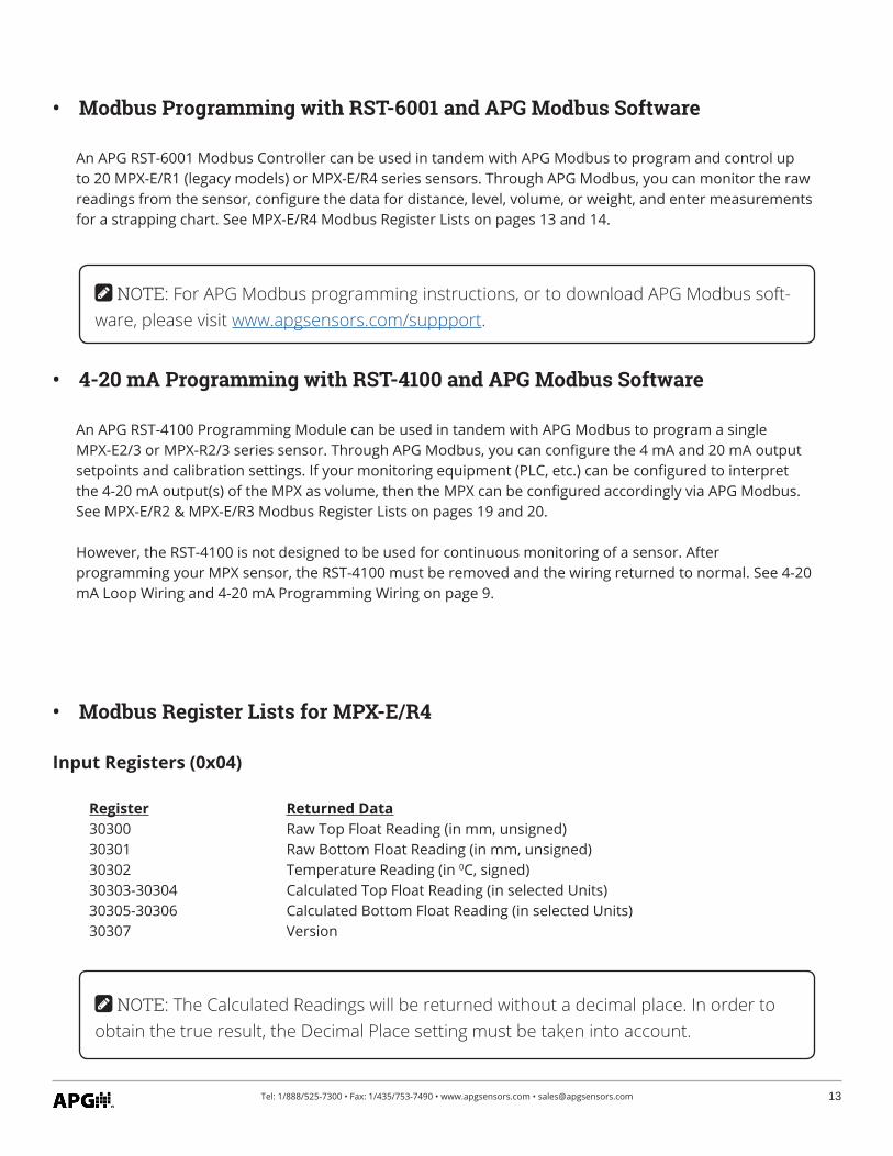
Input Registers (0x04)
Register Returned Data30300 Raw Top Float Reading (in mm, unsigned)30301 Raw Bottom Float Reading (in mm, unsigned)30302 Temperature Reading (in 0C, signed)30303-30304 Calculated Top Float Reading (in selected Units) 30305-30306 Calculated Bottom Float Reading (in selected Units)30307 Version
NOTE: The Calculated Readings will be returned without a decimal place. In order to obtain the true result, the Decimal Place setting must be taken into account.
14 Tel: 1/888/525-7300 • Fax: 1/435/753-7490 • www.apgsensors.com • [email protected]
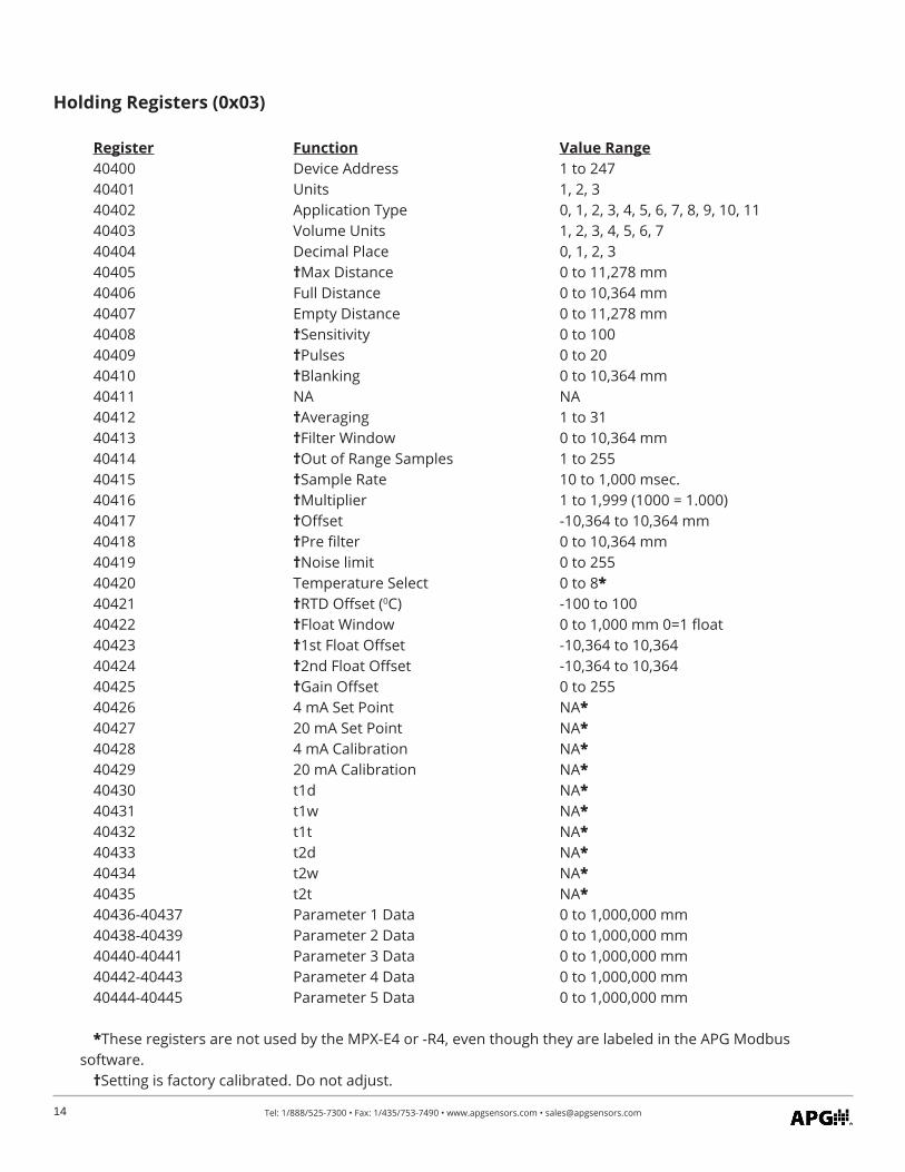
Holding Registers (0x03)
Register Function Value Range40400 Device Address 1 to 24740401 Units 1, 2, 3 40402 Application Type 0, 1, 2, 3, 4, 5, 6, 7, 8, 9, 10, 1140403 Volume Units 1, 2, 3, 4, 5, 6, 740404 Decimal Place 0, 1, 2, 340405 †Max Distance 0 to 11,278 mm40406 Full Distance 0 to 10,364 mm40407 Empty Distance 0 to 11,278 mm 40408 †Sensitivity 0 to 10040409 †Pulses 0 to 2040410 †Blanking 0 to 10,364 mm40411 NA NA40412 †Averaging 1 to 3140413 †Filter Window 0 to 10,364 mm40414 †Out of Range Samples 1 to 255 40415 †Sample Rate 10 to 1,000 msec.40416 †Multiplier 1 to 1,999 (1000 = 1.000)40417 †Offset -10,364 to 10,364 mm40418 †Pre filter 0 to 10,364 mm40419 †Noise limit 0 to 25540420 Temperature Select 0 to 8*40421 †RTD Offset (0C) -100 to 10040422 †Float Window 0 to 1,000 mm 0=1 float40423 †1st Float Offset -10,364 to 10,36440424 †2nd Float Offset -10,364 to 10,36440425 †Gain Offset 0 to 25540426 4 mA Set Point NA*40427 20 mA Set Point NA*40428 4 mA Calibration NA*40429 20 mA Calibration NA*40430 t1d NA* 40431 t1w NA*40432 t1t NA*40433 t2d NA*40434 t2w NA*40435 t2t NA*40436-40437 Parameter 1 Data 0 to 1,000,000 mm 40438-40439 Parameter 2 Data 0 to 1,000,000 mm 40440-40441 Parameter 3 Data 0 to 1,000,000 mm40442-40443 Parameter 4 Data 0 to 1,000,000 mm 40444-40445 Parameter 5 Data 0 to 1,000,000 mm
*These registers are not used by the MPX-E4 or -R4, even though they are labeled in the APG Modbus software.
†Setting is factory calibrated. Do not adjust.
15Tel: 1/888/525-7300 • Fax: 1/435/753-7490 • www.apgsensors.com • [email protected]
• MPX-E/R4 Modbus Sensor Parameters
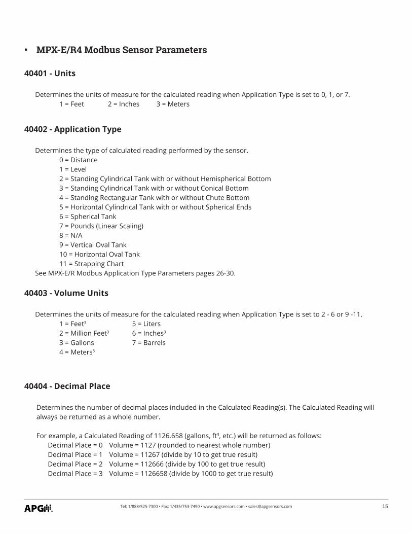
40401 - Units
Determines the units of measure for the calculated reading when Application Type is set to 0, 1, or 7. 1 = Feet 2 = Inches 3 = Meters
40402 - Application Type
Determines the type of calculated reading performed by the sensor. 0 = Distance 1 = Level 2 = Standing Cylindrical Tank with or without Hemispherical Bottom 3 = Standing Cylindrical Tank with or without Conical Bottom 4 = Standing Rectangular Tank with or without Chute Bottom 5 = Horizontal Cylindrical Tank with or without Spherical Ends 6 = Spherical Tank 7 = Pounds (Linear Scaling) 8 = N/A 9 = Vertical Oval Tank 10 = Horizontal Oval Tank 11 = Strapping ChartSee MPX-E/R Modbus Application Type Parameters pages 26-30.
40403 - Volume Units
Determines the units of measure for the calculated reading when Application Type is set to 2 - 6 or 9 -11. 1 = Feet3 5 = Liters 2 = Million Feet3 6 = Inches3 3 = Gallons 7 = Barrels 4 = Meters3
40404 - Decimal Place
Determines the number of decimal places included in the Calculated Reading(s). The Calculated Reading will always be returned as a whole number.
For example, a Calculated Reading of 1126.658 (gallons, ft3, etc.) will be returned as follows: Decimal Place = 0 Volume = 1127 (rounded to nearest whole number) Decimal Place = 1 Volume = 11267 (divide by 10 to get true result) Decimal Place = 2 Volume = 112666 (divide by 100 to get true result) Decimal Place = 3 Volume = 1126658 (divide by 1000 to get true result)
16 Tel: 1/888/525-7300 • Fax: 1/435/753-7490 • www.apgsensors.com • [email protected]
40405 - Maximum Distance (Factory Calibrated)
Sets the distance (beginning from the Zero Reference) to the point where the sensor will stop looking for float signals, usually the bottom of the stem. A float beyond the Maximum Distance value will not be detect-ed.
40406 - Full Distance
Sets the positive distance (beginning from the sensor Zero Reference) to the point where the monitored vessel is considered full.
40407 - Empty Distance
Sets the positive distance (beginning from the Zero Reference) to the point where the monitored vessel is considered empty (usually the bottom of the stem).
40408 - Sensitivity (Factory Calibrated)
Sets the level of gain that is applied to the returning float signal.
40409 - Pulses (Factory Calibrated)
Controls the duration of the signal being sent down the magnetostrictive wire.
40410 - Blanking (Factory Calibrated)
Sets the blanking distance, which is the zone from the Zero Reference of the sensor to the point from which the first signal will be valid. Signals from a float in the blanking area will be ignored.
40412 - Averaging (Factory Calibrated)
Sets the number of qualified received float signals to average for the raw reading. Qualified received signals are placed in a first-in, first-out buffer, the contents of which are averaged for the raw reading. The larger the number of qualified received signals being averaged, the smoother the reading will be, and the slower the reading will be to react to quickly changing targets.
17Tel: 1/888/525-7300 • Fax: 1/435/753-7490 • www.apgsensors.com • [email protected]
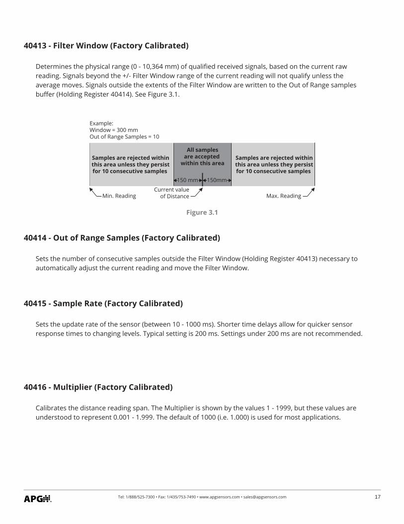
Figure 3.1
Example: Window = 300 mmOut of Range Samples = 10
Min. Reading Max. Reading
150 mm 150mm
Current valueof Distance
All samplesare accepted
within this areaSamples are rejected within this area unless they persist for 10 consecutive samples
Samples are rejected within this area unless they persist for 10 consecutive samples
40413 - Filter Window (Factory Calibrated)
Determines the physical range (0 - 10,364 mm) of qualified received signals, based on the current raw reading. Signals beyond the +/- Filter Window range of the current reading will not qualify unless the average moves. Signals outside the extents of the Filter Window are written to the Out of Range samples buffer (Holding Register 40414). See Figure 3.1.
40414 - Out of Range Samples (Factory Calibrated)
Sets the number of consecutive samples outside the Filter Window (Holding Register 40413) necessary to automatically adjust the current reading and move the Filter Window.
40415 - Sample Rate (Factory Calibrated)
Sets the update rate of the sensor (between 10 - 1000 ms). Shorter time delays allow for quicker sensor response times to changing levels. Typical setting is 200 ms. Settings under 200 ms are not recommended.
40416 - Multiplier (Factory Calibrated)
Calibrates the distance reading span. The Multiplier is shown by the values 1 - 1999, but these values are understood to represent 0.001 - 1.999. The default of 1000 (i.e. 1.000) is used for most applications.
18 Tel: 1/888/525-7300 • Fax: 1/435/753-7490 • www.apgsensors.com • [email protected]
40417 - Offset (Factory Calibrated)
Sets the Zero Reference of the sensor, the point from which the calculated distance is measured.
40418 - Pre filter
Defines the physical range (0 - 10,364 mm) of the start up (pre-filter) window. Four sample readings must be found within the Pre filter window for the MPX sensor to successfully start up.This register is used for factory diagnostics only.
40419 - Noise limit
Sets the limit for number of signals (0-255) outside the Pre filter range for the MPX at start up. If the Noise Limit is reached before four readings register within the Pre filter window, the MPX will not start up.This register is used for factory diagnostics only.
40420 - Temperature Select
Selects the temperature sensor reading to be displayed in Input Register 30302.
MPX-E/R4 sensors are limited to a single RTD sensor in the stem. Only options 0 and 8 work for the MPX-E/R4.
0 = RTD 1 = Digital Temperature Sensor A 5 = Digital Temperature Sensor E 2 = Digital Temperature Sensor B 6 = 3 = Digital Temperature Sensor C 7 = 4 = Digital Temperature Sensor D 8 = Digital Temperature Sensor on Circuit Board
40421 - RTD Offset C° (Factoy Calibrated)
Calibrates the RTD termperature sensor.
NOTE: MPX-E1 and MPX-R1 legacy models will only work with option 0.
19Tel: 1/888/525-7300 • Fax: 1/435/753-7490 • www.apgsensors.com • [email protected]
40422 - Float Window (Factory Calibrated)
Sets the distance (0 - 1000 mm) between the first (i.e. top) float and the point at which the sensor will begin looking for the second (bottom) float. 0 indicates a single float.
40424 - 2nd Float Offset (Factory Calibrated)
Used to calibrate bottom float reading (-10,364 - 10,364 mm).
40423 - 1st Float Offset (Factory Calibrated)
Used to calibrate top float reading (-10,364 - 10,364 mm).
40425 - Gain Offset (Factory Calibrated)
Used to move the centerline of the float response signal to optimize signal strength (0 - 255).
• APG Modbus Register Lists for MPX-E/R2 and MPX-E/R3
Input Registers (0x04)
Register Returned Data30300 Raw Top Float Reading (in mm, unsigned)30301 Raw Bottom Float Reading (in mm, unsigned)30302 Temperature Reading (in 0C, signed)30303-30304 Calculated Top Float Reading (in selected Units) 30305-30306 Calculated Bottom Float Reading (in selected Units)30307 Version
NOTE: Input Register values for MPX-E/R2 and MPX-E/R3 are only visible while pro-gramming via the RST-4100.
20 Tel: 1/888/525-7300 • Fax: 1/435/753-7490 • www.apgsensors.com • [email protected]
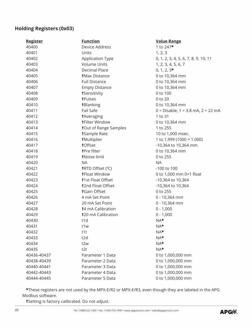
Holding Registers (0x03)
Register Function Value Range40400 Device Address 1 to 247*40401 Units 1, 2, 3 40402 Application Type 0, 1, 2, 3, 4, 5, 6, 7, 8, 9, 10, 1140403 Volume Units 1, 2, 3, 4, 5, 6, 740404 Decimal Place 0, 1, 2, 3*40405 †Max Distance 0 to 10,364 mm40406 Full Distance 0 to 10,364 mm40407 Empty Distance 0 to 10,364 mm 40408 †Sensitivity 0 to 10040409 †Pulses 0 to 2040410 †Blanking 0 to 10,364 mm40411 Fail Safe 0 = Disable, 1 = 3.8 mA, 2 = 22 mA40412 †Averaging 1 to 3140413 †Filter Window 0 to 10,364 mm40414 †Out of Range Samples 1 to 255 40415 †Sample Rate 10 to 1,000 msec.40416 †Multiplier 1 to 1,999 (1000 = 1.000)40417 †Offset -10,364 to 10,364 mm40418 †Pre filter 0 to 10,364 mm40419 †Noise limit 0 to 25540420 NA NA40421 †RTD Offset (0C) -100 to 10040422 †Float Window 0 to 1,000 mm 0=1 float40423 †1st Float Offset -10,364 to 10,36440424 †2nd Float Offset -10,364 to 10,36440425 †Gain Offset 0 to 25540426 4 mA Set Point 0 - 10,364 mm40427 20 mA Set Point 0 - 10,364 mm40428 †4 mA Calibration 0 - 1,00040429 †20 mA Calibration 0 - 1,00040430 t1d NA* 40431 t1w NA*40432 t1t NA*40433 t2d NA*40434 t2w NA*40435 t2t NA*40436-40437 Parameter 1 Data 0 to 1,000,000 mm 40438-40439 Parameter 2 Data 0 to 1,000,000 mm 40440-40441 Parameter 3 Data 0 to 1,000,000 mm40442-40443 Parameter 4 Data 0 to 1,000,000 mm 40444-40445 Parameter 5 Data 0 to 1,000,000 mm
*These registers are not used by the MPX-E/R2 or MPX-E/R3, even though they are labeled in the APG Modbus software.
†Setting is factory calibrated. Do not adjust.
21Tel: 1/888/525-7300 • Fax: 1/435/753-7490 • www.apgsensors.com • [email protected]
• MPX-E/R2 and MPX-E/R3 APG Modbus Sensor Parameters
40401 - Units
Determines the units of measure for the Calculated Reading when Application Type is set to 0, 1, or 7. 1 = Feet 2 = Inches 3 = Meters For MPX-E/R2 and MPX-E/R3, this is seen only when using APG Modbus to program the MPX. This setting does not affect the 4-20 mA output.
40402 - Application Type
Determines the type of Calculated Reading performed by the sensor. 0 = Distance 1 = Level 2 = Standing Cylindrical Tank with or without Hemispherical Bottom 3 = Standing Cylindrical Tank with or without Conical Bottom 4 = Standing Rectangular Tank with or without Chute Bottom 5 = Horizontal Cylindrical Tank with or without Spherical Ends 6 = Spherical Tank 7 = Pounds (Linear Scaling) 8 = N/A 9 = Vertical Oval Tank 10 = Horizontal Oval Tank 11 = Strapping ChartSee MPX-E/R Modbus Application Type Parameters pages 26-30.
For the MPX-E/R2 and MPX-E/R3, the 4-20 mA output can be scaled for linear output over distance/level or scaled for linear output over volume. When setup in any of the volumetric application types, the 4-20mA output becomes linear with regards to the volume (linear mA change per gallon, liter, etc.)
40403 - Volume Units
Determines the units of measure for the Calculated Reading when Application Type is set to 2 - 6 or 9 -11. 1 = Feet3 5 = Liters 2 = Million Feet3 6 = Inches3 3 = Gallons 7 = Barrels 4 = Meters3
40404 - Decimal Place
Determines the number of decimal places included in the Calculated Reading(s). For MPX-E/R2 and MPX-E/R3, this is seen only when using APG Modbus to program the MPX. This setting does not affect the 4-20 mA output.
22 Tel: 1/888/525-7300 • Fax: 1/435/753-7490 • www.apgsensors.com • [email protected]
40411 - Fail Safe
Sets the output condition that the MPX will revert to in the event of a loss of return signal condition. 0 = Disable (no fail safe output) 1 = 3.8 mA 2 = 22 mA
40408 - Sensitivity (Factory Calibrated)
Sets the level of gain that is applied to the returning float signal.
40409 - Pulses (Factory Calibrated)
Controls the duration of the signal being sent down the magnetostrictive wire.
40410 - Blanking (Factory Calibrated)
Sets the blanking distance, which is the zone from the Zero Reference of the sensor to the point from which the first signal will be valid. Signals from a float in the blanking area will be ignored.
40406 - Full Distance
Sets the positive distance (beginning from the sensor Zero Reference) to the point where the monitored vessel is considered full.
40407 - Empty Distance
Sets the positive distance (beginning from the Zero Reference) to the point where the monitored vessel is considered empty (usually the bottom of the stem).
40405 - Maximum Distance (Factory Calibrated)
Sets the distance (beginning from the Zero Reference) to the point where the sensor will stop looking for float signals, usually the bottom of the stem. A float beyond the Maximum Distance value will not be detect-ed.
23Tel: 1/888/525-7300 • Fax: 1/435/753-7490 • www.apgsensors.com • [email protected]
40413 - Filter Window (Factory Calibrated)
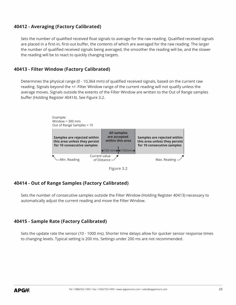
Determines the physical range (0 - 10,364 mm) of qualified received signals, based on the current raw reading. Signals beyond the +/- Filter Window range of the current reading will not qualify unless the average moves. Signals outside the extents of the Filter Window are written to the Out of Range samples buffer (Holding Register 40414). See Figure 3.2.
Figure 3.2
40414 - Out of Range Samples (Factory Calibrated)
Sets the number of consecutive samples outside the Filter Window (Holding Register 40413) necessary to automatically adjust the current reading and move the Filter Window.
40415 - Sample Rate (Factory Calibrated)
Sets the update rate the sensor (10 - 1000 ms). Shorter time delays allow for quicker sensor response times to changing levels. Typical setting is 200 ms. Settings under 200 ms are not recommended.
40412 - Averaging (Factory Calibrated)
Sets the number of qualified received float signals to average for the raw reading. Qualified received signals are placed in a first-in, first-out buffer, the contents of which are averaged for the raw reading. The larger the number of qualified received signals being averaged, the smoother the reading will be, and the slower the reading will be to react to quickly changing targets.
Example: Window = 300 mmOut of Range Samples = 10
Min. Reading Max. Reading
150 mm 150mm
Current valueof Distance
All samplesare accepted
within this areaSamples are rejected within this area unless they persist for 10 consecutive samples
Samples are rejected within this area unless they persist for 10 consecutive samples
24 Tel: 1/888/525-7300 • Fax: 1/435/753-7490 • www.apgsensors.com • [email protected]
40422 - Float Window (Factory Calibrated)
Sets the distance (0 - 1000 mm) between the first (i.e. top) float and the point at which the sensor will begin looking for the second (bottom) float. This essentially functions as a secondary blanking distance for the minimum depth of the top fluid. Set to 0 for single float.
40416 - Multiplier (Factory Calibrated)
Calibrates the distance reading span. The Multiplier is shown by the values 1 - 1999, but these values are understood to represent 0.001 - 1.999. The default of 1000 (i.e. 1.000) is used for most applications.
40417 - Offset (Factory Calibrated)
Sets the Zero Reference of the sensor, the point from which the calculated distance is measured.
40418 - Pre filter
Defines the physical range (0 - 10,364 mm) of the start up (pre-filter) window. Four sample readings must be found within the Pre filter window for the MPX sensor to successfully start up.This register is used for factory diagnostics only.
40419 - Noise limit
Sets the limit for number of signals (0-255) outside the Pre filter range for the MPX at start up. If the Noise Limit is reached before four readings register within the Pre filter window, the MPX will not start up.This register is used for factory diagnostics only.
40421 - RTD Offset C° (Factory Calibrated)
Calibrates the RTD termperature sensor.
25Tel: 1/888/525-7300 • Fax: 1/435/753-7490 • www.apgsensors.com • [email protected]
40424 - 2nd Float Offset (Factory Calibrated)
Used to calibrate bottom float reading (-10,364 - 10,364 mm).
40423 - 1st Float Offset (Factory Calibrated)
Used to calibrate top float reading (-10,364 - 10,364 mm).
40425 - Gain Offset (Factory Calibrated)
Used to move the centerline of the float response signal to optimize signal strength (0 - 255).
40427 - 20mA Set
Used to set the distance which will correspond to an output of 20 mA. For Application 1 (Distance), this is measured from the Zero Reference. For all other applications (Level & Volumetric) this is measured from the bottom of the probe.
40426 - 4mA Set
Used to set the distance which will correspond to an output of 4 mA. For Application 1 (Distance), this is measured from the Zero Reference. For all other applications (Level & Volumetric) this is measured from the bottom of the probe.
40428 - 4mA Cal (Factory Calibrated)
Used to calibrate the 4 mA output of the MPX-E/R2 or -E/R3.
40429 - 20mA Cal (Factory Calibrated)
Used to calibrate the 20 mA output of the MPX-E/R2 or -E/R3.
26 Tel: 1/888/525-7300 • Fax: 1/435/753-7490 • www.apgsensors.com • [email protected]
Application 0 - Distance
Register Function Value Range40400 Device Address 1 to 24740401 Units 1 = Feet, 2 = Inches, 3 = Meters 40402 Application Type 040403 Volume Units --40404 Decimal (Calculated) 0 - 3
Application 1 - Level
Register Function Value Range40400 Device Address 1 to 24740401 Units 1 = Feet, 2 = Inches, 3 = Meters 40402 Application Type 140403 Volume Units --40404 Decimal (Calculated) 0 - 3
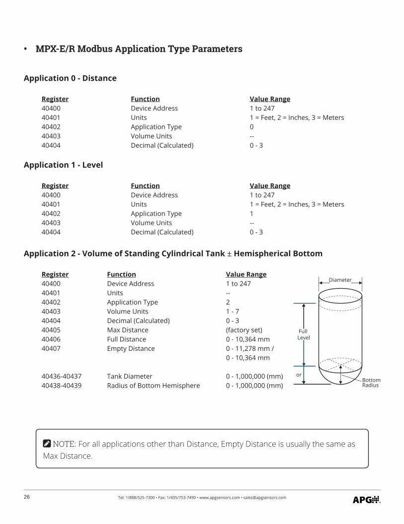
Application 2 - Volume of Standing Cylindrical Tank ± Hemispherical Bottom
Register Function Value Range40400 Device Address 1 to 24740401 Units -- 40402 Application Type 240403 Volume Units 1 - 740404 Decimal (Calculated) 0 - 340405 Max Distance (factory set)40406 Full Distance 0 - 10,364 mm40407 Empty Distance 0 - 11,278 mm / 0 - 10,364 mm
40436-40437 Tank Diameter 0 - 1,000,000 (mm)40438-40439 Radius of Bottom Hemisphere 0 - 1,000,000 (mm)
Diameter
Full Level
BottomRadius
or
• MPX-E/R Modbus Application Type Parameters
NOTE: For all applications other than Distance, Empty Distance is usually the same as Max Distance.
27Tel: 1/888/525-7300 • Fax: 1/435/753-7490 • www.apgsensors.com • [email protected]
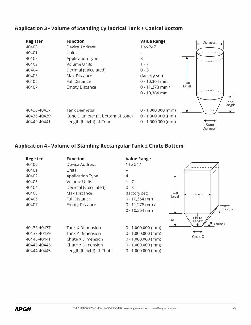
Application 3 - Volume of Standing Cylindrical Tank ± Conical Bottom
Register Function Value Range40400 Device Address 1 to 24740401 Units -- 40402 Application Type 340403 Volume Units 1 - 740404 Decimal (Calculated) 0 - 340405 Max Distance (factory set)40406 Full Distance 0 - 10,364 mm40407 Empty Distance 0 - 11,278 mm / 0 - 10,364 mm
40436-40437 Tank Diameter 0 - 1,000,000 (mm)40438-40439 Cone Diameter (at bottom of cone) 0 - 1,000,000 (mm)40440-40441 Length (height) of Cone 0 - 1,000,000 (mm)
Application 4 - Volume of Standing Rectangular Tank ± Chute Bottom
Register Function Value Range40400 Device Address 1 to 24740401 Units -- 40402 Application Type 440403 Volume Units 1 - 740404 Decimal (Calculated) 0 - 340405 Max Distance (factory set)40406 Full Distance 0 - 10,364 mm40407 Empty Distance 0 - 11,278 mm / 0 - 10,364 mm
40436-40437 Tank X Dimension 0 - 1,000,000 (mm)40438-40439 Tank Y Dimension 0 - 1,000,000 (mm)40440-40441 Chute X Dimension 0 - 1,000,000 (mm)40442-40443 Chute Y Dimension 0 - 1,000,000 (mm)40444-40445 Length (height) of Chute 0 - 1,000,000 (mm)
Diameter
FullLevel
Cone Length
ConeDiameter
Tank X
ChuteLength
Tank Y
Full Level
orChute Y
Chute X
28 Tel: 1/888/525-7300 • Fax: 1/435/753-7490 • www.apgsensors.com • [email protected]
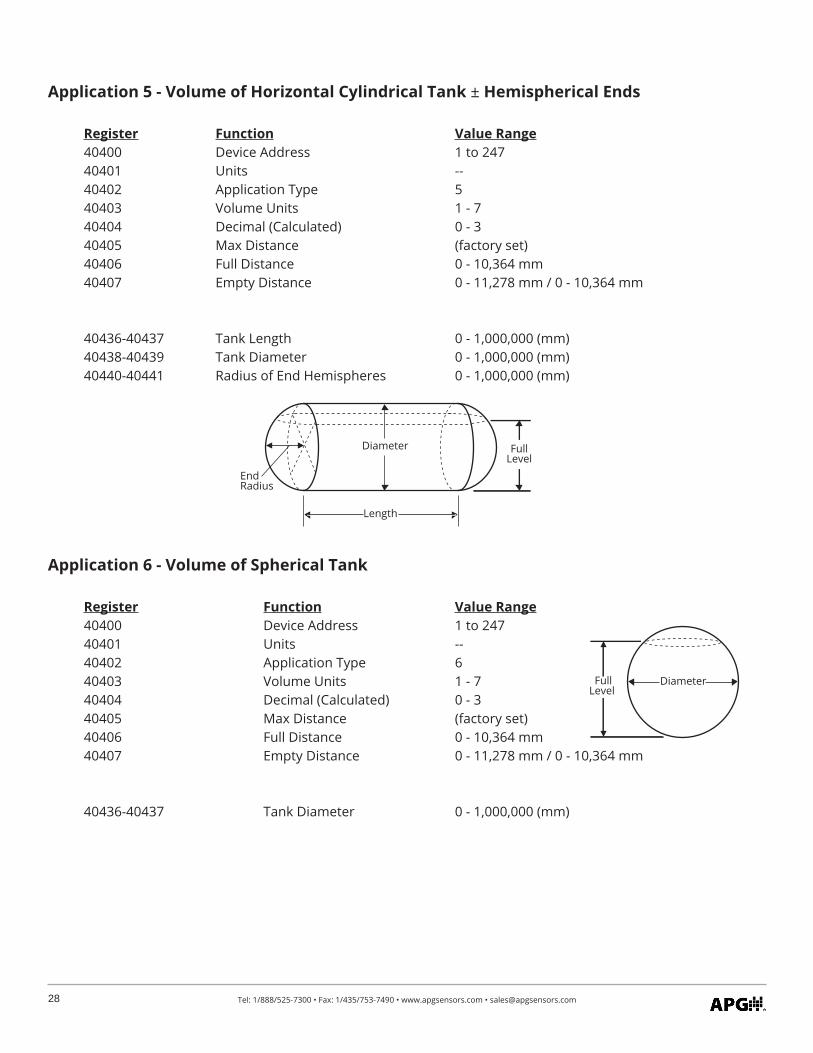
Application 5 - Volume of Horizontal Cylindrical Tank ± Hemispherical Ends
Register Function Value Range40400 Device Address 1 to 24740401 Units -- 40402 Application Type 540403 Volume Units 1 - 740404 Decimal (Calculated) 0 - 340405 Max Distance (factory set)40406 Full Distance 0 - 10,364 mm40407 Empty Distance 0 - 11,278 mm / 0 - 10,364 mm
40436-40437 Tank Length 0 - 1,000,000 (mm)40438-40439 Tank Diameter 0 - 1,000,000 (mm)40440-40441 Radius of End Hemispheres 0 - 1,000,000 (mm)
Application 6 - Volume of Spherical Tank
Register Function Value Range40400 Device Address 1 to 24740401 Units -- 40402 Application Type 640403 Volume Units 1 - 740404 Decimal (Calculated) 0 - 340405 Max Distance (factory set)40406 Full Distance 0 - 10,364 mm40407 Empty Distance 0 - 11,278 mm / 0 - 10,364 mm
40436-40437 Tank Diameter 0 - 1,000,000 (mm)
Diameter
Length
FullLevel
End Radius
FullLevel
Diameter
29Tel: 1/888/525-7300 • Fax: 1/435/753-7490 • www.apgsensors.com • [email protected]
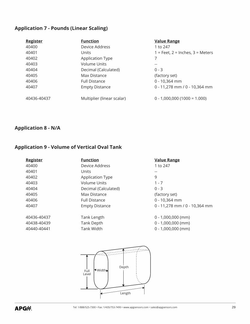
Application 9 - Volume of Vertical Oval Tank
Register Function Value Range40400 Device Address 1 to 24740401 Units -- 40402 Application Type 940403 Volume Units 1 - 740404 Decimal (Calculated) 0 - 340405 Max Distance (factory set)40406 Full Distance 0 - 10,364 mm40407 Empty Distance 0 - 11,278 mm / 0 - 10,364 mm
40436-40437 Tank Length 0 - 1,000,000 (mm)40438-40439 Tank Depth 0 - 1,000,000 (mm)40440-40441 Tank Width 0 - 1,000,000 (mm)
Application 7 - Pounds (Linear Scaling)
Register Function Value Range40400 Device Address 1 to 24740401 Units 1 = Feet, 2 = Inches, 3 = Meters 40402 Application Type 740403 Volume Units --40404 Decimal (Calculated) 0 - 340405 Max Distance (factory set)40406 Full Distance 0 - 10,364 mm40407 Empty Distance 0 - 11,278 mm / 0 - 10,364 mm
40436-40437 Multiplier (linear scalar) 0 - 1,000,000 (1000 = 1.000)
Full Level
Depth
Length
Width
Application 8 - N/A
30 Tel: 1/888/525-7300 • Fax: 1/435/753-7490 • www.apgsensors.com • [email protected]
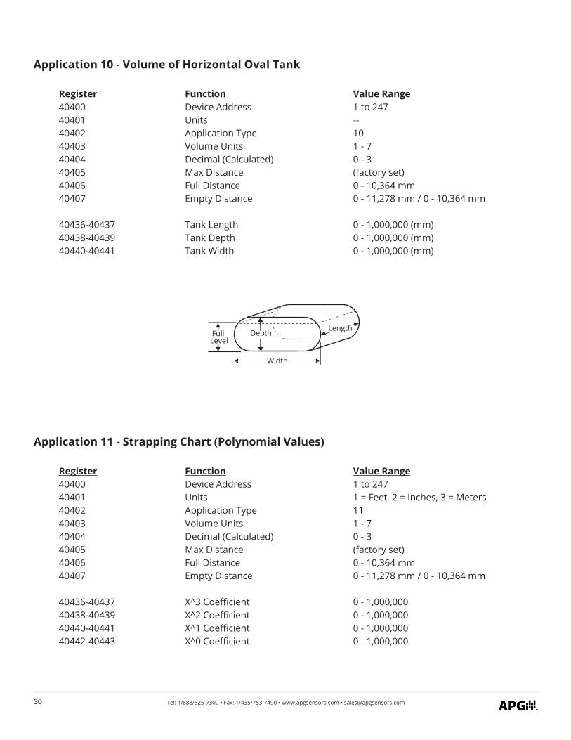
Application 10 - Volume of Horizontal Oval Tank
Register Function Value Range40400 Device Address 1 to 24740401 Units -- 40402 Application Type 1040403 Volume Units 1 - 740404 Decimal (Calculated) 0 - 340405 Max Distance (factory set)40406 Full Distance 0 - 10,364 mm40407 Empty Distance 0 - 11,278 mm / 0 - 10,364 mm
40436-40437 Tank Length 0 - 1,000,000 (mm)40438-40439 Tank Depth 0 - 1,000,000 (mm)40440-40441 Tank Width 0 - 1,000,000 (mm)
Application 11 - Strapping Chart (Polynomial Values)
Register Function Value Range40400 Device Address 1 to 24740401 Units 1 = Feet, 2 = Inches, 3 = Meters 40402 Application Type 1140403 Volume Units 1 - 740404 Decimal (Calculated) 0 - 340405 Max Distance (factory set)40406 Full Distance 0 - 10,364 mm40407 Empty Distance 0 - 11,278 mm / 0 - 10,364 mm
40436-40437 X^3 Coefficient 0 - 1,000,00040438-40439 X^2 Coefficient 0 - 1,000,00040440-40441 X^1 Coefficient 0 - 1,000,00040442-40443 X^0 Coefficient 0 - 1,000,000
Length
Width
Depth Full Level
31Tel: 1/888/525-7300 • Fax: 1/435/753-7490 • www.apgsensors.com • [email protected]
Your MPX level sensor is designed to be low maintenance. However, in general, you should:• Periodically inspect your MPX to ensure the stem and floats are free of any heavy buildup that might
impede the movement of the floats.• Ensure the housing cover is snuggly secured. If the cover becomes damaged or is misplaced, order a
replacement immediately.
Chapter 4: Maintenance
Should your MPX level sensor require service, please contact the factory via phone, email, or online chat. We will issue you a Return Material Authorization (RMA) number with instructions.
• Phone: 888-525-7300• Email: [email protected]• Online chat at www.apgsensors.com
Please have your part number and serial number available. See Warranty and Warranty Restrictions for more information.
IMPORTANT: All repairs and adjustments of the MPX level sensor must be made by the factory. Modifying, disassembling, or altering the MPX, other than patching the chemi-cal resistant coating on an MPX-E Chemical probe, is strictly prohibited.
• General Care
• Repair and Returns
NOTE: If the damaged area is greater than 0.1”, it is recommended to use a supple-mental patch of chemical resistant coating.
The MPX-E Chemical’s chemical resistant coating is a durable thermoplastic. This means that if damage occurs, repair is possible:
• Use a heat gun on a low setting to heat the damaged location until coating becomes soft and mallea-ble. If coating begins to ripple or bubble, too much heat has been applied.
• With a blunt object, gently smear the coating to recover the damaged area.• Allow chemical resistant coating patch to cool before reinstalling probe.• Keep MPX-E Chemical probe and chemical resistant coating away from flammable material during
repair.
32 Tel: 1/888/525-7300 • Fax: 1/435/753-7490 • www.apgsensors.com • [email protected]
Chapter 5: Hazardous Location Installation and Certification
• Hazardous Location and Non-Incendive Wiring Diagram
33Tel: 1/888/525-7300 • Fax: 1/435/753-7490 • www.apgsensors.com • [email protected]
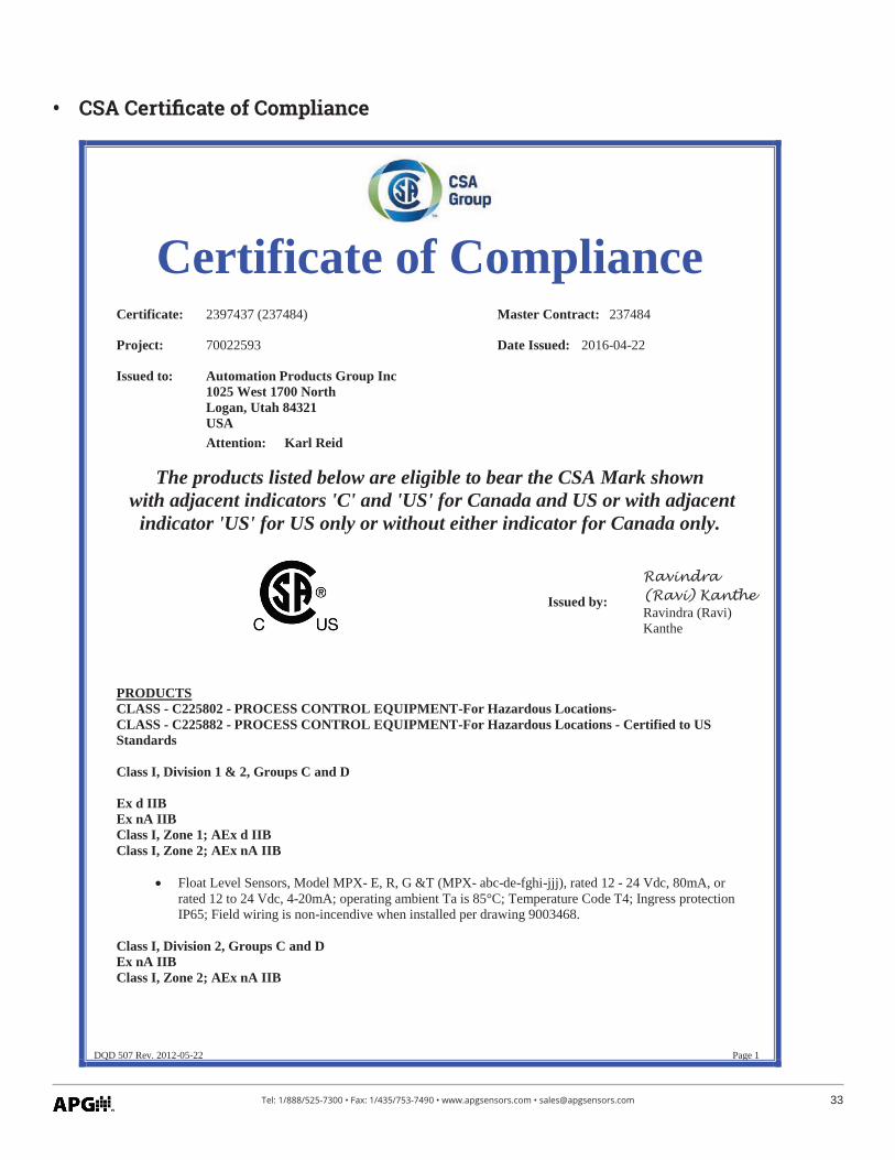
• CSA Certificate of Compliance
DQD 507 Rev. 2012-05-22 Page 1
Certificate of Compliance Certificate: 2397437 (237484) Master Contract: 237484
Project: 70022593 Date Issued: 2016-04-22
Issued to: Automation Products Group Inc 1025 West 1700 North Logan, Utah 84321 USAAttention: Karl Reid
The products listed below are eligible to bear the CSA Mark shown with adjacent indicators 'C' and 'US' for Canada and US or with adjacent
indicator 'US' for US only or without either indicator for Canada only.
Issued by:
Ravindra (Ravi) KantheRavindra (Ravi) Kanthe
PRODUCTS CLASS - C225802 - PROCESS CONTROL EQUIPMENT-For Hazardous Locations- CLASS - C225882 - PROCESS CONTROL EQUIPMENT-For Hazardous Locations - Certified to US Standards
Class I, Division 1 & 2, Groups C and D
Ex d IIB Ex nA IIB Class I, Zone 1; AEx d IIB Class I, Zone 2; AEx nA IIB
Float Level Sensors, Model MPX- E, R, G &T (MPX- abc-de-fghi-jjj), rated 12 - 24 Vdc, 80mA, or rated 12 to 24 Vdc, 4-20mA; operating ambient Ta is 85°C; Temperature Code T4; Ingress protection IP65; Field wiring is non-incendive when installed per drawing 9003468.
Class I, Division 2, Groups C and D Ex nA IIB Class I, Zone 2; AEx nA IIB

34 Tel: 1/888/525-7300 • Fax: 1/435/753-7490 • www.apgsensors.com • [email protected]
Certificate: 2397437 Project: 70022593
Master Contract: 237484 Date Issued: 2016-04-22
DQD 507 Rev. 2012-05-22 Page 2
Float Level Sensors, Model MPX- F (model MPX- abc-de-fghi-jjj), rated 12 - 24 Vdc, 80mA, or rated 12 to 24 Vdc, 4-20mA; operating ambient Ta is 85°C; Temperature Code T4; Ingress protection IP65; Field wiring is non-incendive when installed per drawing 9003468
Notes for all equipment:
1. The model code breakdown is as follows: a= E, R, F, G or T; b= 1, 2, 3 or 4; c= A,B or C, d= A, B, C, D, E, F, G, Z, X, V, T, R, M, or J; e= N, B, D, Y, W, U, S, P, L, K, or I; f= F, R, P, S, N, or O; g= 1, 1.5, 2, 2.5, 3, 3.5, 4, 5, 6; h=W or S; i= A, B, C or D; and j= 12–153 for the 1/2" stem Type E or 48–300 for the 1" stem Type R, Type G and Type T or 120-456 for Flex stem Type F.
2. The equipment is intended to be installed as required by the applicable electrical code (CEC, NEC) and as specified by the manufacturers Installation Instructions.
3. The installation will be inspected by the authority with jurisdiction in the area where installed.
APPLICABLE REQUIREMENTS
CSA C22.2 No 0-10 General Requirements – Canadian Electrical Code, Part II – Tenth Edition
CSA C22.2 No 30-M1986 (Reaffirmed 2007)
Explosion-Proof Enclosures for Use in Class I Hazardous Locations Industrial Products – Third Edition
CSA C22.2 No 142-M1987 (Reaffirmed 2014)
Process Control Equipment Industrial Products – Third Edition
CSA C22.2 No 213-M1987 (Reaffirmed 2008)
Non-incendive Electrical Equipment for Use in Class I, Division 2 Hazardous Locations Industrial Products – First Edition
CSA C22.2 No 60079-0-07 Electrical apparatus for explosive gas atmospheres – Part 0: General requirements – First Edition
CSA C22.2 No 60079-1-07 Electrical apparatus for explosive gas atmospheres – Part 1: Flameproof enclosures "d" – First Edition
CSA E60079-15-02 (Reaffirmed 2006)
Electrical Apparatus for Explosive Gas Atmospheres –Part 15: Type of Protection "n" – Second Edition
UL 508Industrial Control Equipment - Seventeenth Edition; Reprint with Revisions Through and Including April 15, 2010
UL 1203
Explosion-Proof and Dust-Ignition-Proof Electrical Equipment for Use in Hazardous (Classified) Locations - Fourth Edition; Reprint with Revisions through and Including October 28, 2009
ANSI/ISA-12.12.01-2007 Nonincendive Electrical Equipment for Use in Class I and II, Division 2 and Class III, Divisions 1 and 2 Hazardous (Classified) Locations
UL 60079-0 - 5th Ed (Dec 2009) Explosive atmospheres - Part 0 Equipment - General requirements
35Tel: 1/888/525-7300 • Fax: 1/435/753-7490 • www.apgsensors.com • [email protected]
Certificate: 2397437 Project: 70022593
Master Contract: 237484 Date Issued: 2016-04-22
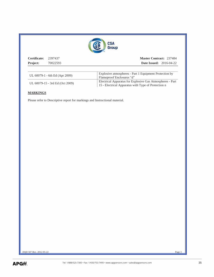
DQD 507 Rev. 2012-05-22 Page 3
UL 60079-1 - 6th Ed (Apr 2009) Explosive atmospheres - Part 1 Equipment Protection by Flameproof Enclosures “d”
UL 60079-15 - 3rd Ed (Oct 2009) Electrical Apparatus for Explosive Gas Atmospheres - Part 15 - Electrical Apparatus with Type of Protection n
MARKINGS
Please refer to Descriptive report for markings and Instructional material.
36 Tel: 1/888/525-7300 • Fax: 1/435/753-7490 • www.apgsensors.com • [email protected]
DQD 507 Rev. 2012-05-22 Page 1
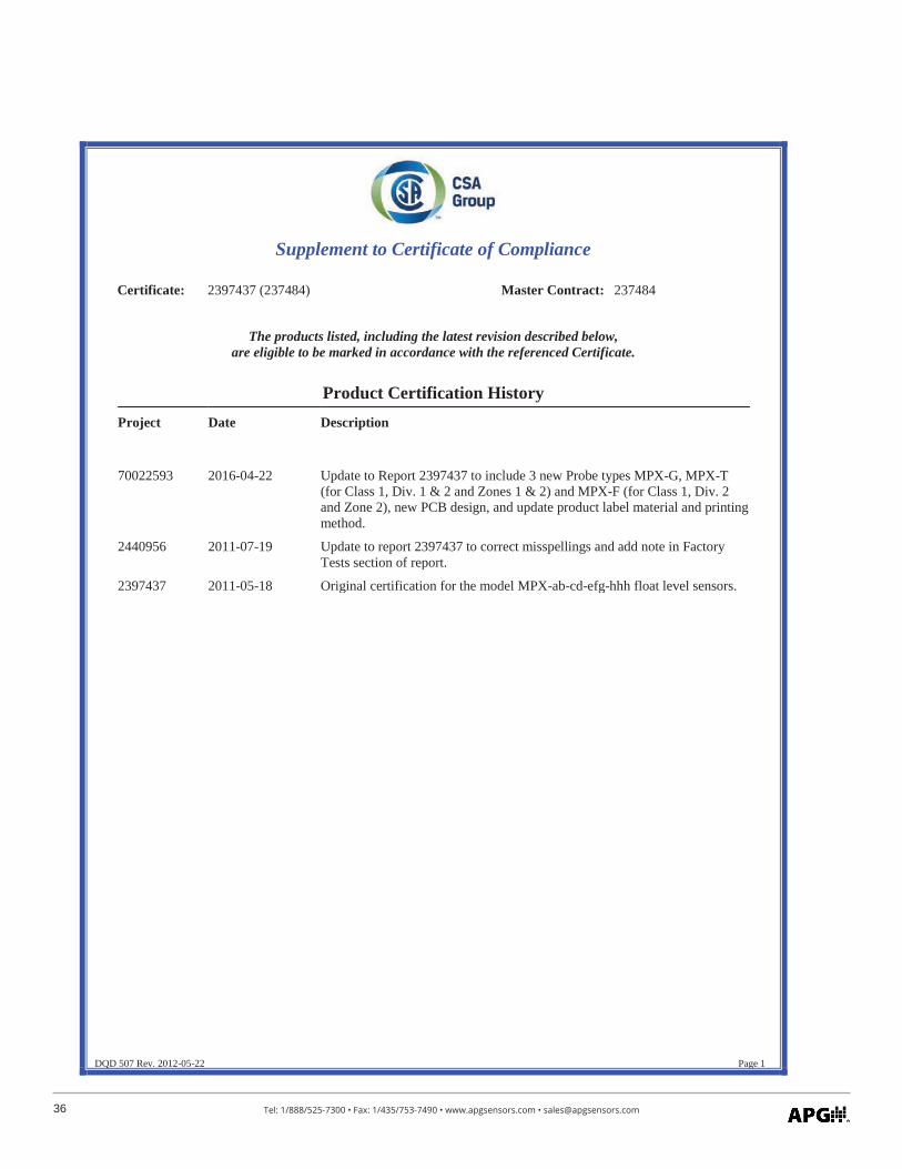
Supplement to Certificate of Compliance
Certificate: 2397437 (237484) Master Contract: 237484
The products listed, including the latest revision described below, are eligible to be marked in accordance with the referenced Certificate.
Product Certification History Project Date Description
70022593 2016-04-22 Update to Report 2397437 to include 3 new Probe types MPX-G, MPX-T(for Class 1, Div. 1 & 2 and Zones 1 & 2) and MPX-F (for Class 1, Div. 2 and Zone 2), new PCB design, and update product label material and printing method.
2440956 2011-07-19 Update to report 2397437 to correct misspellings and add note in Factory Tests section of report.
2397437 2011-05-18 Original certification for the model MPX-ab-cd-efg-hhh float level sensors.

37Tel: 1/888/525-7300 • Fax: 1/435/753-7490 • www.apgsensors.com • [email protected]

Automation Products Group, Inc.Tel: 1/888/525-7300 • Fax: 1/435/753-7490 • www.apgsensors.com • [email protected]
APGR