
MPU11-AC/DC-GPIO4D -...
139
Centroid MPU11, AC/DC, GPIO4D Install Manual 7 11 25 36 45 60 87/99 114 123 www.centroidcnc.com MPU11-AC/DC-GPIO4D Chapter 1: Whats Included Chapter 2: Bench Test Hardware Chaper 3: Software Installation Chapter 4: Bench Test Software Chapter 6: Final Software Configuration Appendix A/B: Windows 8/7 configuration Appendix C: General Troubleshooting Appendix D: AC/DC TroubleShooting Appendix E: Stock Centroid Encoders 126 CENTROID_mpu11-AC-DC-gpio4d_install_manual.pdf rev 8-15-14 Copyright © 2014 CENTROID AC/DC servo drive based CNC control system step by step installation instructions Chapter 5: In cabinet Installation 128 136 Appendix F: Manual configuration of AC/DC servo drive motor parameters Appendix G: Compatible Servo Motors
Transcript of MPU11-AC/DC-GPIO4D -...

Centroid MPU11, AC/DC, GPIO4D Install Manual
7
11
25
36
45
60
87/99
114
123
www.centroidcnc.com
MPU11-AC/DC-GPIO4D
Chapter 1: Whats Included
Chapter 2: Bench Test Hardware
Chaper 3: Software Installation
Chapter 4: Bench Test Software
Chapter 6: Final Software Configuration
Appendix A/B: Windows 8/7 configuration
Appendix C: General Troubleshooting
Appendix D: AC/DC TroubleShooting
Appendix E: Stock Centroid Encoders 126
CENTROID_mpu11-AC-DC-gpio4d_install_manual.pdf rev 8-15-14 Copyright © 2014 CENTROID
AC/DC servo drive based CNC control system step by step installation instructions
Chapter 5: In cabinet Installation
128
136
Appendix F: Manual configuration of AC/DC servo drive motor parameters
Appendix G: Compatible Servo Motors

DRIVE WARRANTY DOES NOT COVER DAMAGE BY FAULTY MOTORS OR WIRING.
The information provided by CENTROID relating to wiring, installation, and operation of CNC components is intended onlyas a guide, and in all cases a qualified technician and all applicable local codes and laws must be consulted. CENTROID makesno claims about the completeness or accuracy of the information provided, as it may apply to an infinite number of field conditions.
As CNC control products from CENTROID can be installed on a wide variety of machine tools NOT sold or support byCENTROID, you MUST consult and follow all safety instructions provided by your machine tool manufacture regardingthe safe operation of your machine and unique application.
Servo Motor Handling
When working with servo motors:
· NEVER pick up or carry the motor by the cables or the shaft. (Always carry by the frame.) Use a crane or lift to move the motor when necessary.
· NEVER drop or subject the motor to impact. The servo motor is a precision device.
· NEVER set heavy or sharp objects on the motor or cables. Do not step or sit on the motor or cables.
· NEVER use a metal hammer on any part of the motor. If it is absolutely necessary to use a hammer, use a plastic hammer.
Keep the motor properly secured and away from the edge of the work area when servicing the motor, as a dropped motor could cause personal injury or destroy the motor.
Page 2 of 139 T:\DOCS\manuals\CENTROID_mpu11-AC-DC-GPIO4D_install_manual\CENTRIOD_mpu11-AC-DC-GPIO4D_install_manual 8-15-14.odt

Basic Safety Procedures and Best Practices
For Motors
Be safely dressed when handling a motor. Wear safety shoes and gloves. Avoid loose clothing which can get caught on the motor. Be careful not to let hair get caught in the rotary section of the motor. Do not handle the motor with wet hands. Shut off the power before working on a motor. Wait at least 5 minutes after the motor is shut off before touching any power terminals. Ensure that the motor and motor related components are mounted securely. Ensure that the base or frame to which the motor is mounted to is strong enough. Do not touch the rotary section of the motor when it is running unless instructed to. When attaching a component having inertia to the motor, ensure any imbalance between the motor and component is minimized. Be sure to attach a key to a motor with a keyed shaft. Use the motor in appropriate environmental conditions. Do not store flammables in close proximity to the motor. When not in use,store the motor in a dry location between 0° to 40° C. Do not remove the nameplate from a motor.
For Circuit Boards
Minimize handling circuit boards as much as possible. If you must hold a circuit board, grab it by the edges as shown below in figure 2. Avoid touching any of the circuits, components, or component leads. Improper handling lead to ESD (electrostatic discharge) which can damage the PCB, and shorten the operational lifespan.
Keep the work are free from static generating materials such as Styrofoam, vinyl, plastic, and fabrics.
Page 3 of 139 T:\DOCS\manuals\CENTROID_mpu11-AC-DC-GPIO4D_install_manual\CENTRIOD_mpu11-AC-DC-GPIO4D_install_manual 8-15-14.odt
Figure 1.Improper PCB Handling Figure 2.
Proper PCB Handling
CONTENTS
INTRODUCTION......................................................................................................................................................................................... 6
CHAPTER 1 WHAT'S INCLUDED
1.1 MPU11............................................................................................................................................................................ 7
1.2 Crimpers.......................................................................................................................................................................... 8
1.2 GPIO4D.......................................................................................................................................................................... 9
1.3 AC/DC........................................................................................................................................................................... 10
CHAPTER 2 BENCH TEST SETUP
2.1 Introduction................................................................................................................................................................... 11
2.2 Power Supply Configuration......................................................................................................................................... 12
2.3 Communication Configuration...................................................................................................................................... 14
2.4 Encoder Setup.............................................................................................................................................................. 17
2.5 MPU11 Accessories...................................................................................................................................................... 19
2.6 Powering On and Verifying LED States........................................................................................................................21
CHAPTER 3 SOFTWARE INSTALLATION
3.1 Software Preinstallation................................................................................................................................................ 25
3.2 CNC11 and PLC Installation......................................................................................................................................... 26
3.3 AC/DC Setup Wizard.................................................................................................................................................... 30
CHAPTER 4 BENCH TEST
4.1 Software Configuration.................................................................................................................................................. 36
4.2 Bench Testing the AC/DC............................................................................................................................................. 41
4.3 Bench Testing the GPIO4D and MPU11....................................................................................................................... 43
CHAPTER 5 ELECTRICAL CABINET INSTALLATION
5.1 Introduction to Electrical Cabinet Layout......................................................................................................................45
5.2 Electrically Configuring Inputs on the GPIO4D.............................................................................................................48
5.3 Wiring Motors................................................................................................................................................................ 50
5.4 Wiring AC/DC Brake Resistor....................................................................................................................................... 51
5.5 Wiring E-Stop............................................................................................................................................................... 52
5.6 Wiring Limit Switches................................................................................................................................................... 54
5.7 Wiring Lube Pump........................................................................................................................................................ 56
5.8 Wiring Coolant Pump.................................................................................................................................................... 57
5.9 Wiring Spindle.............................................................................................................................................................. 58
Page 4 of 139 T:\DOCS\manuals\CENTROID_mpu11-AC-DC-GPIO4D_install_manual\CENTRIOD_mpu11-AC-DC-GPIO4D_install_manual 8-15-14.odt
CHAPTER 6 FINAL SOFTWARE CONFIGURATION
6.1 Introduction................................................................................................................................................................... 60
6.2 Confirm AC/DC Communication................................................................................................................................... 60
6.3 Confirm Encoder Communication................................................................................................................................. 61
6.4 AC Encoder Alignment.................................................................................................................................................. 62
6.5 Jogging and Motor Direction......................................................................................................................................... 67
6.6 Coarse Adjustment of DRO Position............................................................................................................................. 70
6.7 Homing the machine..................................................................................................................................................... 72
6.8 Calculating Maximum Feed Rate.................................................................................................................................. 74
6.9 Tuning your AC/DC
6.9.1 A Basic Introduction to Tuning and PID.........................................................................................................75
6.9.2 Tuning Software Setup.................................................................................................................................. 76
6.9.3 Acceleration Tuning...................................................................................................................................... 77
6.9.4 Inertia Tuning................................................................................................................................................ 78
6.9.5 Kp Tuning...................................................................................................................................................... 79
6.9.6 Kd Tuning...................................................................................................................................................... 80
6.10 Fine Adjustment of DRO Position............................................................................................................................... 81
6.11 Removing backlash..................................................................................................................................................... 84
6.12 Deadstart.................................................................................................................................................................... 86
6.13 Other Misc Tuning Information.................................................................................................................................... 86
6.14 Performing a System Test........................................................................................................................................... 86
APPENDICES
Appendix A – Windows 8 Preinstallation.............................................................................................................................. 87
Appendix B – Windows 7 Preinstallation............................................................................................................................. 99
Appendix C – General Troubleshooting............................................................................................................................. 114
Appendix D – AC/DC Troubleshooting............................................................................................................................... 123
Appendix E – Stock Centroid Encoders............................................................................................................................. 126
Appendix F – Manual Configuration of the AC/DC Motors Parameters.............................................................................128
Appendix G – Compatible Motors...................................................................................................................................... 136
Page 5 of 139 T:\DOCS\manuals\CENTROID_mpu11-AC-DC-GPIO4D_install_manual\CENTRIOD_mpu11-AC-DC-GPIO4D_install_manual 8-15-14.odt

Introduction
This manual describes how to install the Centroid CNC (Computer Numerical Control) system with an AC/DC servo drive. ThePC based system provides up to eight axes of closed loop servo interpolated motion, controlled by industry standard G-Codes.
Ours can be used for the CNC control of milling machines, routers, lathes, flame cutters, plasma cutters, laser cutters, water jet cutters, drill presses, grinders, and other specialized applications.
This installation manual covers the most common AC/DC hardware setups. Specifically, this manual will focus on the following equipment:
• Centroid AC/DC drive,
• Centroid GPIO4D PLC (programmable logic controller)
• Centroid MPU11 (motion processing unit)
• Installation of Centroid Software on a Computer
This manual does not cover an AC/DC drive used with a Centroid RTK4 PLC or Centroid PLCADD1616 PLC, but users of those products will benefit from the information in this manual.
Before You Begin
Before getting started, please take the time to familiarize yourself with the schematics, manuals, and installation instructions.
While doing the installation, it is very important that you follow the instructions in order and that you follow them exactly. Doing the installation incrementally and testing as you go will allow you to immediately isolate the cause of any problems that you may run into. Additional troubleshooting is included in the appendices.
If you are retrofitting Fanuc motors, it is important that perform the steps listed in the “Fanuc Retrofit Manual” before starting this manual.
Motor Compatibility
The AC/DC supports over 60 different motors. Including over 50 different Fanuc motors, 6 SEM motors, and 4 Mecapian motors. The easiest way to install an AC/DC is with motors provided by Centroid. Users should only use motors on the list of motors found in Appendix E.
What if your motor is not on the list? Most motors with a continuous stall current of above 5 amps or below 30 amps can be adapted to work with the AC/DC. (This gives the AC/DC an approximate range of 500 watts to 6,000 watts or 0.7 hp to 7.8 hp.) For an evaluation fee, most unsupported motors can be sent into Centroid to have the parameters needed for CNC11 software calculated. After a motor model has been evaluated once, those software parameters work on all motors of that model number. Call sales for more information.
In the future, Centroid plans on bringing an advanced set of features to the Centroid CNC11 software allowing users to calculate their own software parameters without the need to have Centroid evaluate their motors.
The First Steps
If you are retrofitting Fanuc motors, follow the Fanuc Retrofits Manual BEFORE starting on this manual. The next step is to visually inspect everything that came with your kit. Use the charts on the following pages to check for any missing parts and to familiarize yourself with the hardware.
Page 6 of 139 Introduction T:\DOCS\manuals\CENTROID_mpu11-AC-DC-GPIO4D_install_manual\CENTRIOD_mpu11-AC-DC-GPIO4D_install_manual 8-15-14.odt

CHAPTER 1WHAT'S INCLUDED
1.1 MPU11
The MPU11 stands for “motion processing unit (version) 11”. The MPU11 is a motion control card that will act as the “brain” for your CNC system. The MPU11 provides the link connecting your computer to all of your drives, PLC, and accessories.
The following components are included with your MPU11:1. MPU11 ...........................................................................................................................Part Number 110122. Power supply....................................................................................................................Part Number 13313. Power supply AC input cable............................................................................................Part Number 39524. Power supply DC output cable ........................................................................................Part Number 39515. Twenty four pin MPG connector.......................................................................................Part Number 59846. Ten Pin Probe connector..................................................................................................Part Number 59187. Twelve Pin Jog panel Connector......................................................................................Part Number 59198. Twenty six crimp pins for MPG connector ........................................................................Part Number 59839. Twenty four crimp pins for jog panel connector and probe connector ..............................Part Number 5511
Page 7 of 139 1.1 MPU11T:\DOCS\manuals\CENTROID_mpu11-AC-DC-GPIO4D_install_manual\CENTRIOD_mpu11-AC-DC-GPIO4D_install_manual 8-15-14.odt
2
3
4
1
5
6
7
9
8

1.2 Crimpers
Crimp Pin Part Number 5511 (Used for making jog panel and probe cables)The appropriate hand crimping tools are available from TE Connectivity as “PRO-CRIMPER III Hand Tool Assembly 91387-1 with Die Assembly 91387-2 (26-22 AWG)” or “PRO-CRIMPER III Hand Tool Assembly 91388-1 with Die Assembly 91388-2 (22-18 AWG)”. These tools are sold separately and can be purchased from most major electronics components distributors such as Digi-Key.
Fully assembled cables for jog panels and probes can be bought through Centroid.
Crimp Pin Part Number 5983 (Used for making MPG cables)The appropriate hand crimping are available from JST as “YRS-245”. These tools are sold separately and can be purchased from most major electronics components distributors such as Digi-Key.
Fully assembled cables MPG cables can bought through Centroid.
Page 8 of 139 1.2 CrimpersT:\DOCS\manuals\CENTROID_mpu11-AC-DC-GPIO4D_install_manual\CENTRIOD_mpu11-AC-DC-GPIO4D_install_manual 8-15-14.odt

1.3 GPIO4D
The GPIO4D stands for “General purpose input / output (for up to) four drives”. The GPIO4D is a PLC, meaning it is a “programmable logic controller”.
Essentially the GPIO4D is a set of computer controlled inputs and outputs. On an AC/DC system, the GPIO4D will provide I/O (“input / output”) for subsystems such as lubricant, coolant, and the spindle drive.
The following components are included with your GPIO4D:
1. GPIO4D..........................................................................................................................Part Number 110182. Power supply....................................................................................................................Part Number 13313. Power supply AC input cable............................................................................................Part Number 39524. Power supply DC output cable.........................................................................................Part Number 39515. Optic fibers labeled “1” and “3”.......................................................................................Part Number 100186. 2 twenty position terminal blocks .....................................................................................Part Number 34507. Twelve position terminal block .........................................................................................Part Number 15518. 4 seven position terminal blocks ......................................................................................Part Number 26119. 2 ten position terminal blocks...........................................................................................Part Number 390410. 5 five volt SIPS (color and appearance may vary)............................................................Part Number 395611. 5 twelve volt SIPS (color and appearance may vary).......................................................Part Number 4152
Page 9 of 139 1.3 GPIO4DT:\DOCS\manuals\CENTROID_mpu11-AC-DC-GPIO4D_install_manual\CENTRIOD_mpu11-AC-DC-GPIO4D_install_manual 8-15-14.odt
6
1
2
3
4
5
7
8
9
1110
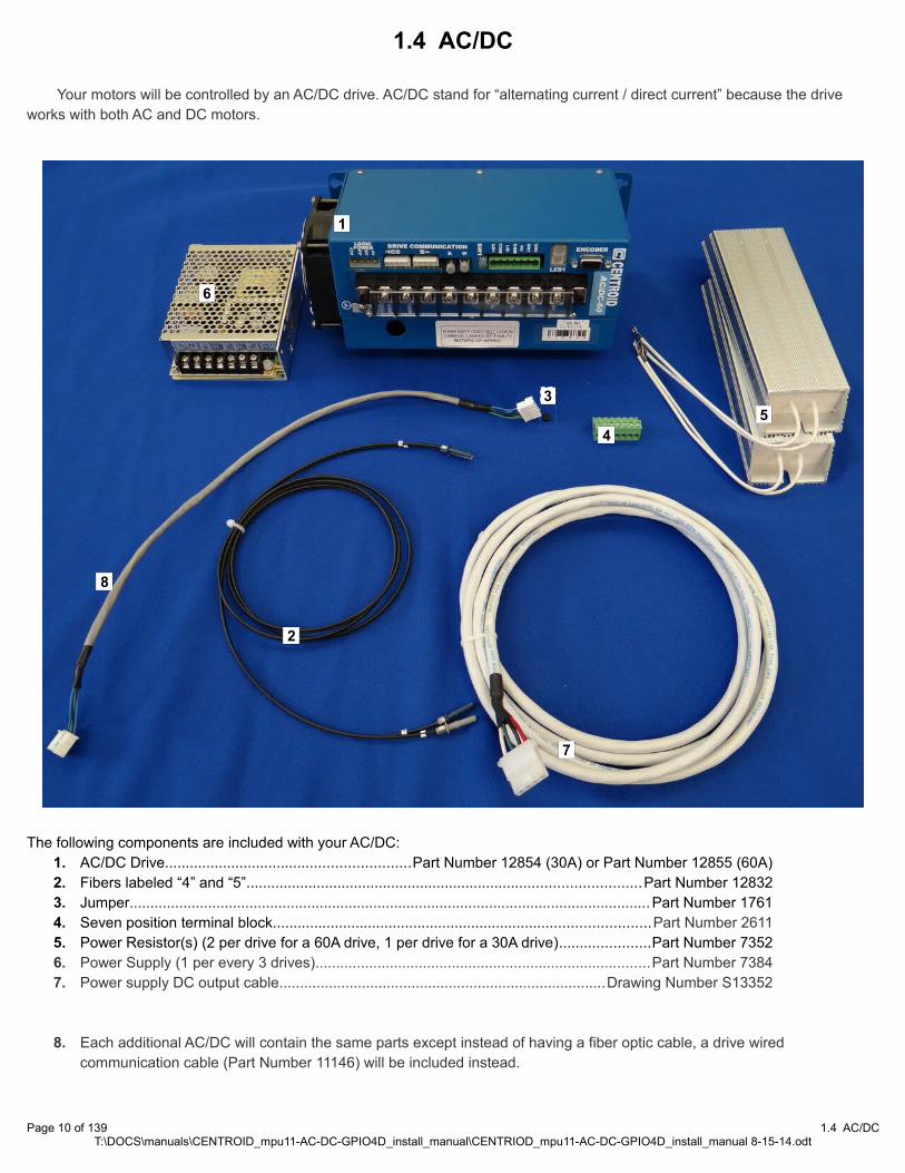
1.4 AC/DC
Your motors will be controlled by an AC/DC drive. AC/DC stand for “alternating current / direct current” because the drive works with both AC and DC motors.
The following components are included with your AC/DC:1. AC/DC Drive...........................................................Part Number 12854 (30A) or Part Number 12855 (60A)2. Fibers labeled “4” and “5”...............................................................................................Part Number 128323. Jumper..............................................................................................................................Part Number 17614. Seven position terminal block...........................................................................................Part Number 26115. Power Resistor(s) (2 per drive for a 60A drive, 1 per drive for a 30A drive)......................Part Number 73526. Power Supply (1 per every 3 drives).................................................................................Part Number 73847. Power supply DC output cable...............................................................................Drawing Number S13352
8. Each additional AC/DC will contain the same parts except instead of having a fiber optic cable, a drive wired communication cable (Part Number 11146) will be included instead.
Page 10 of 139 1.4 AC/DCT:\DOCS\manuals\CENTROID_mpu11-AC-DC-GPIO4D_install_manual\CENTRIOD_mpu11-AC-DC-GPIO4D_install_manual 8-15-14.odt
2
1
3
45
6
7
8
CHAPTER 2 BENCH TEST
2.1 Introduction
The first step in installing your new system is performing a bench test. A “bench test” is connecting all of the electronics together to test them before installing the system in a machine. This test is usually done on a work bench, hence the name. A bench test allows you to:
• Troubleshoot hardware and software problems early on, before they can cause permanent damage to the system.
• Identify missing or defective hardware before installing the system
• Allows for greater visibility when troubleshooting than an electrical cabinet.
• Should a serious issue arise, it gives the user a knowledge base that allows Centroid Technical Support to more quickly and efficiently solve problem.
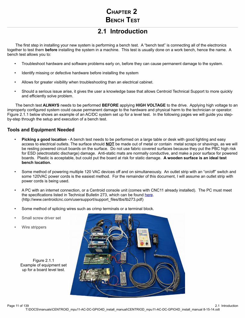
The bench test ALWAYS needs to be performed BEFORE applying HIGH VOLTAGE to the drive. Applying high voltage to animproperly configured system could cause permanent damage to the hardware and physical harm to the technician or operator. Figure 2.1.1 below shows an example of an AC/DC system set up for a level test. In the following pages we will guide you step-by-step through the setup and execution of a bench test.
Tools and Equipment Needed
• Picking a good location - A bench test needs to be performed on a large table or desk with good lighting and easy access to electrical outlets. The surface should NOT be made out of metal or contain metal scraps or shavings, as we willbe resting powered circuit boards on the surface. Do not use fabric covered surfaces because they put the PBC high risk for ESD (electrostatic discharge) damage. Anti-static mats are normally conductive, and make a poor surface for poweredboards. Plastic is acceptable, but could put the board at risk for static damage. A wooden surface is an ideal test bench location.
• Some method of powering multiple 120 VAC devices off and on simultaneously. An outlet strip with an “on/off” switch and some 120VAC power cords is the easiest method. For the remainder of this document, I will assume an outlet strip with power cords is being used.
• A PC with an internet connection, or a Centroid console unit (comes with CNC11 already installed). The PC must meet the specifications listed in Technical Bulletin 273, which can be found here. (http://www.centroidcnc.com/usersupport/support_files/tbs/tb273.pdf)
• Some method of splicing wires such as crimp terminals or a terminal block.
• Small screw driver set
• Wire strippers
Page 11 of 139 2.1 IntroductionT:\DOCS\manuals\CENTROID_mpu11-AC-DC-GPIO4D_install_manual\CENTRIOD_mpu11-AC-DC-GPIO4D_install_manual 8-15-14.odt
Figure 2.1.1Example of equipment set up for a board level test.
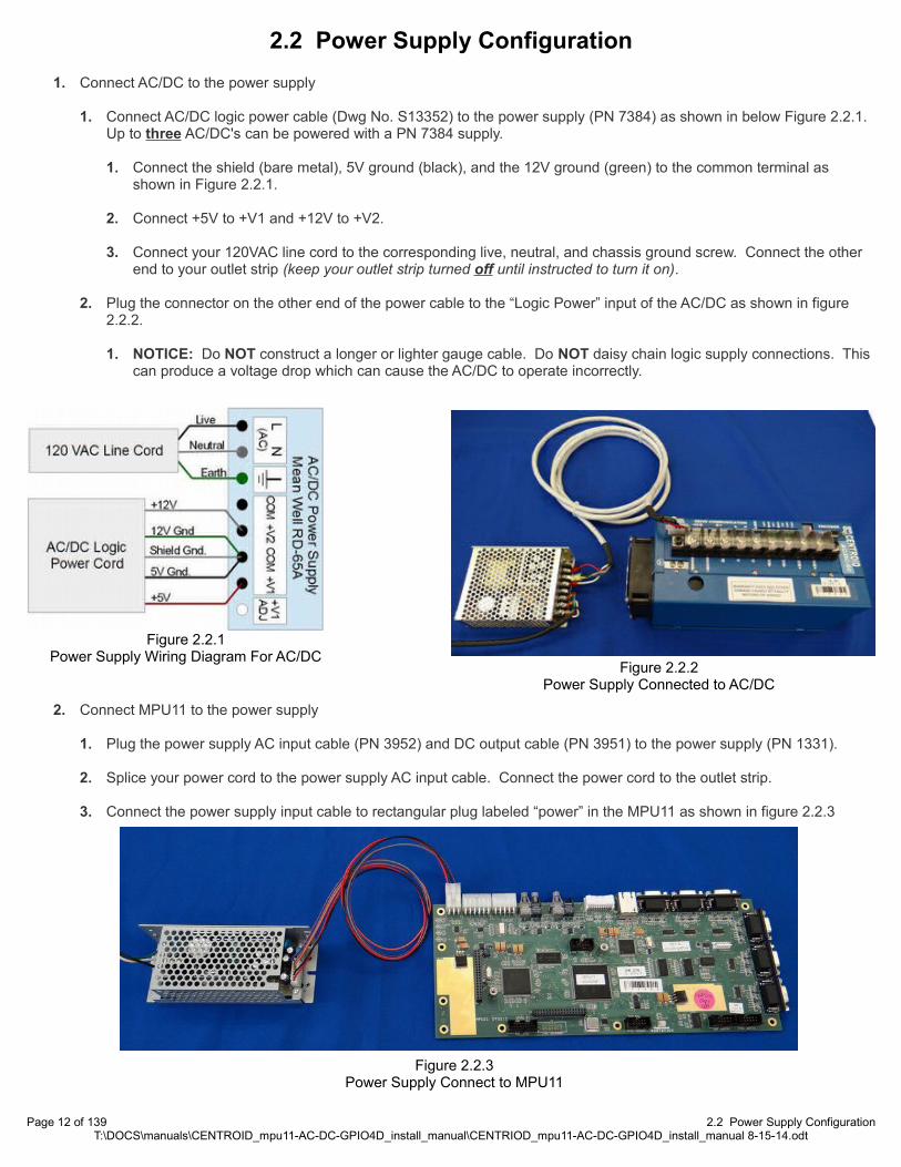
2.2 Power Supply Configuration
1. Connect AC/DC to the power supply
1. Connect AC/DC logic power cable (Dwg No. S13352) to the power supply (PN 7384) as shown in below Figure 2.2.1. Up to three AC/DC's can be powered with a PN 7384 supply.
1. Connect the shield (bare metal), 5V ground (black), and the 12V ground (green) to the common terminal as shown in Figure 2.2.1.
2. Connect +5V to +V1 and +12V to +V2.
3. Connect your 120VAC line cord to the corresponding live, neutral, and chassis ground screw. Connect the other end to your outlet strip (keep your outlet strip turned off until instructed to turn it on).
2. Plug the connector on the other end of the power cable to the “Logic Power” input of the AC/DC as shown in figure 2.2.2.
1. NOTICE: Do NOT construct a longer or lighter gauge cable. Do NOT daisy chain logic supply connections. This can produce a voltage drop which can cause the AC/DC to operate incorrectly.
2. Connect MPU11 to the power supply
1. Plug the power supply AC input cable (PN 3952) and DC output cable (PN 3951) to the power supply (PN 1331).
2. Splice your power cord to the power supply AC input cable. Connect the power cord to the outlet strip.
3. Connect the power supply input cable to rectangular plug labeled “power” in the MPU11 as shown in figure 2.2.3
Page 12 of 139 2.2 Power Supply ConfigurationT:\DOCS\manuals\CENTROID_mpu11-AC-DC-GPIO4D_install_manual\CENTRIOD_mpu11-AC-DC-GPIO4D_install_manual 8-15-14.odt
Figure 2.2.1Power Supply Wiring Diagram For AC/DC
Figure 2.2.2Power Supply Connected to AC/DC
Figure 2.2.3Power Supply Connect to MPU11

3. Connect GPIO4D to the power supply
1. Plug the power supply AC input cable (PN 3952) and DC output cable (PN 3951) to the power supply (PN 1331).
2. Splice your power cord to the power supply AC input cable. Connect the power cord to the outlet strip.
3. Connect the other end of the power supply DC output cable to the twelve pin terminal block connecting to header H6 as shown below in Figure 2.2.4. and in Figure 2.2.5
Page 13 of 139 2.2 Power Supply ConfigurationT:\DOCS\manuals\CENTROID_mpu11-AC-DC-GPIO4D_install_manual\CENTRIOD_mpu11-AC-DC-GPIO4D_install_manual 8-15-14.odt
H6
Figure 2.2.4Power Supply Connected to GPIO4D
Figure 2.2.5Power Supply Wiring Diagram For GPIO4D

2.3 Communication Configuration
4. Configure AC/DC communication
1. AC/DCs need to be chained together with wire or fiber optic cables to allow them to communicate. The AC/DC that is furthest away from the MPU11 in the communication chain will be the first axis. The drive closest to the MPU11 willbe your last axis. An example set up is shown in Figure 2.3.8.
2. On the last axis, connect fibers 5 and 4 (PN 12832) from AC/DC to the MPU11. When connecting fibers match the colors and numbers. (Ex. gray connector to gray socket, fiber 5 to socket 5) as shown below in Figures 2.3.6 and Figure 2.3.7.
3. On the last axis remove or offset the wired input jumper (PN 1761) so that it does not connect both pins as shown in Figure 2.3.8. The wired input jumper will not disable the wired output, only the wired input.
4. Connect the drive communication cable (PN 11146) from the “drive communication out” last axis to the “drive communication in” of the next drive in the communication chain as shown in 2.3.8
Page 14 of 139 2.3 Communication ConfigurationT:\DOCS\manuals\CENTROID_mpu11-AC-DC-GPIO4D_install_manual\CENTRIOD_mpu11-AC-DC-GPIO4D_install_manual 8-15-14.odt
Figure 2.3.6Connect drive communication fibers 4 and 5 to the AC/DC.
Figure 2.3.7Connect drive communication fibers 4 and 5 to the MPU11

5. For rest of the drives in the communication chain, the wired input jumper needs to be connected to both pins as shown. Connect the drive communication cable (PN 11146) from the output of one drive to the input of the next drive as shown below.
Page 15 of 139 2.3 Communication ConfigurationT:\DOCS\manuals\CENTROID_mpu11-AC-DC-GPIO4D_install_manual\CENTRIOD_mpu11-AC-DC-GPIO4D_install_manual 8-15-14.odt
Wired Input Jumper Disabled
Remove or offset the jumper so that it does not connect to both pins to disable the wired communication inputs and
enable the fiber optic inputs labeled “4” and “5”.
Wired Input Jumper Enabled
Jumper enabled. This will disable the fiber optic inputs and enable the wired input.
Figure 2.3.8AC/DC Communication diagram
Last Axis
First Axis

5. Configure MPU11 Communication
1. Connect a shielded Ethernet cable from your MPU11 device to the PC. A shielded Ethernet cable will have a metal clip around the RJ-45 connector it as shown by the blue cable in Figure 2.3.9 Centroid recommends using snagless patch cables from StarTech. StarTech ID# S45PATCH25BL. This information is outlined in Technical Bulletin #251, the latest version can be found here. (http://www.centroidcnc.com/usersupport/support_files/tbs/tb251.pdf)
1. NOTICE: An unshielded cable can cause intermittent PC Data receive errors in the software due to electronic noise and interference.
6. GPIO4D Communication and setup
1. Connect PLC communication fibers labeled “3” and “1” (PN 10018) from the GPIO4D to the MPU11 as shown in Figures 2.3.10 and 2.3.11.
Page 16 of 139 2.3 Communication ConfigurationT:\DOCS\manuals\CENTROID_mpu11-AC-DC-GPIO4D_install_manual\CENTRIOD_mpu11-AC-DC-GPIO4D_install_manual 8-15-14.odt
Figure 2.3.10Connect PLC communication
fibers to the GPIO4D.
Figure 2.3.11Connect PLC communication
fibers to the MPU11.
Figure 2.3.9Unshielded Ethernet cable (gray) compared to Shielded Ethernet cable (blue)
X

2.4 Encoder Set-up
7. Connect the motor encoders. A table of supported Centroid encoders with part numbers is provided in Appendix C, Stock Centroid Encoders.
1. The encoder cables MUST be shielded cables. The shield wire of the encoder cable needs to be grounded to the metal shield of the DB-15 connector as seen in figure 2.4.1. Centriod recommends using a twisted pair cable.
1. NOTE: Failure to do so can cause encoder differential errors in the software.
2. Connect the motor encoders to the AC/DC. Do not use the encoder connectors on the MPU11 (encoders 1-6) when connecting a motor to a AC/DC. Use the encoder connection on the front of the AC/DC as shown in Figures 2.4.2 and2.4.3.
3. AC/DC accepts incremental quadrature encoders and BiSS serial protocol encoders. The type of encoder will be automatically detected when logic power is applied. The encoder must be connected before applying power, or the AC/DC will report an encoder type of “none” and be unable to control a motor. Wiring diagrams for supported encoders are shown below in 2.4.4
1. Incremental quadrature encoders Encoders must have RS422 type differential outputs to work with AC/DC. The outputs have additional voltage level requirements described in the table below:
Characteristic Min. Typ. Max. UnitEncoder channel low level 0.0 0.3 0.5 VEncoder channel high level 3.0 3.5 5.0 V
1. AC Incremental Quadrature Encoders Commutation encoders for use with AC brushless (PMSM) motors have commutation channels (U, V, W) in addition to the position channels (A, B, Z) as shown on the next page. These additional channels are used to indicate rotor position for smooth initial start up. Commutation channels must be aligned using the “move sync” functions in CNC11 when mounting a new encoder. This is detailed later in this document in section “6.4 AC Encoder Alignment”.
2. DC Incremental Quadrature Encoders These encoders for DC brush motors require only A, B, and Z position channels as shown on the next page. Notice that the A and B channels are swapped for DC encodersto reverse the count direction and maintain backward compatibility with older Centroid DC systems.
3. BiSS protocol encoders: These encoders communicate all needed information over only two differential pairs. This type of encoder is available in single and multi-turn absolute versions. The more advanced protocol allows for a very high number of counts per revolution, which enables very smooth motion and high accuracy. For the purpose of a bench test, the encoders do not need to be connected to a motor. If you did not purchase an encoder cable, wire the DB15 connector that connects your encoders to the AC/DC as shown on the next page.
Page 17 of 139 2.4 Encoder Set-upT:\DOCS\manuals\CENTROID_mpu11-AC-DC-GPIO4D_install_manual\CENTRIOD_mpu11-AC-DC-GPIO4D_install_manual 8-15-14.odt
Figure 2.4.2Do not use the encoders on the MPU11 when connecting motors to the AC/DC!
Figure 2.4.3Use the encoders connection on the
front of the AC/DC.
Figure 2.4.1Cable shield grounded to the metal
shield of the D-sub connector.

Encoder Type
Pin
AC IncrementalQuadrature
DCIncrementalQuadrature
BiSSProtocol
1 +A +B -2 +B +A -3 +Z +Z +Data4 +V - -5 - - -6 -A -B -7 -B -A -8 -Z -Z -Data9 +U - +Clock
10 +W - -11 0V 0V 0V12 +5V +5V +5V13 -U - -Clock14 -V - -15 -W - -
Case Shield / Drain Shield / Drain Shield / Drain
Page 18 of 139 2.4 Encoder Set-upT:\DOCS\manuals\CENTROID_mpu11-AC-DC-GPIO4D_install_manual\CENTRIOD_mpu11-AC-DC-GPIO4D_install_manual 8-15-14.odt
Figure 2.4.4All drawings are shown from the perspective of the mating
end of the encoder cable
( As opposed to the end containing the soldered or
crimped connections. )

Count Directions
MotorEncoder Count Direction
(while turning shaft clockwise, looking at mounting flange)Brushless PID screen Abs Pos increases
Brush PID screen Abs Pos decreases
2.5 MPU11 Accessories
8. Connect additional accessories
1. If a jog panel/pendant or MPG was ordered, please connect it to the MPU11 as seen in Figures 2.5.1 and 2.5.2.
9. Connect any additional PLC I/O.
1. The use and operation of additional PLC I/O (Such as PLCADD1616) is beyond the scope if this document and will not be covered in detail. If you have any additional PLC I/O, you should consult the appropriate documentation and hook it up accordingly for the bench test.
Page 19 of 139 2.5 MPU11 AccessoriesT:\DOCS\manuals\CENTROID_mpu11-AC-DC-GPIO4D_install_manual\CENTRIOD_mpu11-AC-DC-GPIO4D_install_manual 8-15-14.odt
Figure 2.5.2MPG
Figure 2.5.1Jog Pendant

Depending on the number drives and accessories, each customers bench test setup will look a little different. When you are finished, it should look somewhat similar to the picture shown below.
Page 20 of 139 2.5 MPU11 AccessoriesT:\DOCS\manuals\CENTROID_mpu11-AC-DC-GPIO4D_install_manual\CENTRIOD_mpu11-AC-DC-GPIO4D_install_manual 8-15-14.odt
Figures 2.5.3AC/DC, MPU11, GPIO4D connect for a bench test.

2.6 Powering On & Verifying LED States
Before powering on, perform a visual inspection of what you have set up so far. Check to make sure no metal object can short against the circuit boards. Check to make sure all wiring is firmly in place.
Switch the outlet strip on, powering on the AC/DCs, MPU11, GPIO4D, and any accessories if applicable.
GPIO4D LED States: Just like the MPU11, the LED's are next to the power connector as shown in Figure 2.6.1. After 15 to 30 seconds all LEDs should initialize to solid green. Make sure that all light are on, indicating the GIO4D has proper power and is communicating with the MPU11.
GPIO4D LED StatesLED Name LED Function Nominal State
PLC OK Indicates that the PLC is communicating with the MPU11 Solid Green
3.3V The PLC has 3.3 volt power. Solid Green
5V The PLC has 5 volt power. Solid Green
+12V The PLC has +12 volt power. Solid Green
-12V The PLC has -12 volt power. Solid Green
Page 21 of 139 2.6 Powering On & Verifying LED StatesT:\DOCS\manuals\CENTROID_mpu11-AC-DC-GPIO4D_install_manual\CENTRIOD_mpu11-AC-DC-GPIO4D_install_manual 8-15-14.odt
Figure 2.6.1LEDs on the GPIO4D

MPU11 LED states: While powering up, there are 4 LED's next to the power connector on the MPU11 that flicker while the MPU11 is initializing as shown in Figure 2.6.2. After 15-30 seconds the LED's should initialize to the state shown in the table below.
MPU11 LED Nominal LED StatesLED Name LED Function Nominal State
FPGA-OK The FPGA is working correctly Solid green
DSP-DEBUG Flashing indicates drive detected. Flashing ~1 per second
DSP-OK The DSP is working correctly Solid Green
+5V The board has 5 volt power. Solid Green
MPU11 LED LED TroubleshootingLED Symptiom Possible Cause Corrective Action
FPGA-OK not lit
MPU11 Not Ready Wait for the MPU11 to start and enter run mode
Internal hardware Fault Return for repair
DSP-OK not lit MPU11 is booting up Wait for the MPU11 to start and enter run mode
DSP-DEBUG LED flashing twenty times per second
MPU11 is detecting hardware Wait for MPU11 to detect hardware and start run mode
DSP-DEBUG and DSP-OK LED flashingalternately eight times per second
FPGA memory test failed Return for repair
DSP-DEBUG and DSP-OK LED both oncontinuous
DSP Failed to initialize Return for repair
Page 22 of 139 2.6 Powering On & Verifying LED StatesT:\DOCS\manuals\CENTROID_mpu11-AC-DC-GPIO4D_install_manual\CENTRIOD_mpu11-AC-DC-GPIO4D_install_manual 8-15-14.odt
Figure 2.6.2LEDs on the MPU11

1. AC/DC LED States: The AC/DC is different from the MPU11 and GPIO4D in the fact that it uses both a seven segment display and LEDs to provide the user with information. Always wait 15 to 30 seconds for the drive to initialize for checking the LED states.
The LEDs on the AC/DC are hidden on the side of the drive opposite of the fan as seen in Figure 2.6.3. You do not need to remove the cover to view the LED's, but for your reference a picture of the logic board with the cover removed is provided in Figure 2.6.4. Make sure the FPGA OK, +5V, and +12V LEDs are solid green. The DSP OK light should flash.
ACDC Logic LED StatesLED Name LED Function Nominal State
Drive Fault Status of the drive fault relay. Turns on when communication isestablished with the software and all drive
faults are cleared.
FPGA OK The FPGA is working correctly. If this light is off, it indicates apossible hardware failure.
Solid Green
DSP Debug Should never be on, not used. Off
DSP OK The flashing once per seconds means the DSP is workingcorrectly. If this light is off, it indicates a possible hardware failure.
Flashing ~1 per second
Enable Axis Indicated when the drive is enabled by the software. Turns on when the drive is enabled by thesoftware.
+5V The drive has 5 volt power. Solid Green
+12V The drive has 12 volt power. Solid Green
Page 23 of 139 2.6 Powering On & Verifying LED StatesT:\DOCS\manuals\CENTROID_mpu11-AC-DC-GPIO4D_install_manual\CENTRIOD_mpu11-AC-DC-GPIO4D_install_manual 8-15-14.odt
Drive Fault
FPGA OK
DSP Debug
DSP OK
Drive Enable
+5V
+12V
Figure 2.6.3LEDs on the side of the drive.
Figure 2.6.4LEDs on the Logic board
Encoder
LogicBoard
PowerBoard

2. AC/DC LED1 (Seven Segment Display) States: Approximately 15-30 seconds after starting LED1 will display a number. If the seven segment display is displaying a solid number without a decimal point it indicates the drive axis number as seen in Figure 2.6.5. If LED1 is flashing with a decimal point it indicates an error as shown in Figure 2.6.6.
If you have a blinking 4, that means the AC/DC is not seeing the limit switches. Since we have not hooked up limit switches, you can disable them by switch SW1 to the down position as shown in Figure 4.2.7. If done correctly, the driveswill all be displaying their drive axis number. A table of other drive errors and their definitions is provided below.
ACDC Seven Segment StatesError
NumberMeaning Cause Corrective Action
1 Communication Error "Wired Input" Jumper set incorrectly orfiber 4 or cable connection not workingproperly
Set jumper properly and check communication cables.
4 Limit Tripped any limit switch is tripped Use the limit defeat switches to disable hardware limits
5 Drive Error A serious fault has caused the drive toshut down
Check HSC Screen for error cause <F7>, <F9>, <F5>
Page 24 of 139 2.6 Powering On & Verifying LED StatesT:\DOCS\manuals\CENTROID_mpu11-AC-DC-GPIO4D_install_manual\CENTRIOD_mpu11-AC-DC-GPIO4D_install_manual 8-15-14.odt
Figure 2.6.5 Drive Number
Figure 2.6.6 Drive Error
(Please note the decimal point)
Limits Switches Enabled
Limit Switches Disabled
Figure 2.6.7Switch SW1

CHAPTER 3SOFTWARE INSTALLATION
3.1 Preinstallation
1. If you have purchased a console unit or computer from Centriod, it already comes with Windows properly configured and the CNC11 software already installed. Please skip to section “3.3 AC/DC Setup Wizard”.
2. If you have a computer with the Microsoft Windows 8 operating system, please skip to Appendix A, Windows 8 preinstallation.
3. If you have a computer with the Microsoft Windows 7 operating system, please skip to Appendix B, Windows 7 preinstallation.
4. Microsoft Windows Xp, Vista, and older versions of Windows are not supported. Mac OS and Linuix are also not supported.
5. Before installing CNC11, all anti-virus and 3rd party firewall software should be uninstalled (not disabled) and your computer rebooted.
1. Nearly 100% of all communication problems between CNC11 and the MPU11 are caused by anti-virus and 3rd party firewall software. Virus software works by stopping unusual or suspicious behavior in software, and will almost always detect the interaction between the MPU11 and the PC as unusual/suspicious and interfere with operation of CNC11. Firewalls work by blocking certain communication ports, and often these ports are needed for operation of CNC11. The default firewall built into Microsoft Windows will work fine with CNC11 if you allow access as specified in this manual.
2. If your corporate policy requires anti-virus software, a third party firewall, or that certain Windows security features be enabled to connect to the network, then Centroid recommends that you keep any computers with CNC11 installed disconnected from the network.
Page 25 of 139 3.1 PreinstallationT:\DOCS\manuals\CENTROID_mpu11-AC-DC-GPIO4D_install_manual\CENTRIOD_mpu11-AC-DC-GPIO4D_install_manual 8-15-14.odt

3.2 CNC11 and PLC Installation
With your bench configuration completely connected and your PC running and powered up as described in section 3, install the CNC11 Software as follows:
1. Download the latest CNC11 Software version. It is important that you download the latest version of the Centroid CNC11 software before continuing. Click on the link below to download the latest version of CNC11 software: CNC11 Software download (http://www.centroidcnc.com/usersupport/support_files/latest_release/cnc11_latest.zip)
2. Copy the downloaded file to your desktop. Depending on your Windows 7 settings, the file you downloaded will be displayed as either cnc11_win7_current.zip or cnc11_win7_current. Copy this file to your desktop and then double click on the file from your desktop.
3. Drag the installation folder from the compressed file to your desktop. The folder in this example is called centroid-cnc11-v312-D, your version maybe newer but the name will be the same other than the “v312” which signifies the CNC11 version number as shown below in Figure 3.2.1.
4. Double click the install folder and double click setup to begin CNC11 install as seen in Figure 3.2.2
5. On a Windows 7 or 8 computer if “User Account Control” is enabled, Windows will ask “Do you want to allow the following program from an unknown publisher to make changes on this computer?”. Click “Yes”.
Page 26 of 139 3.2 CNC11 and PLC InstallationT:\DOCS\manuals\CENTROID_mpu11-AC-DC-GPIO4D_install_manual\CENTRIOD_mpu11-AC-DC-GPIO4D_install_manual 8-15-14.odt
Figure 3.2.1Copy to desktop
Figure 3.2.2Double click “Setup”

6. Select CNC11 Mill and WinPcap for a Mill installation as shown in Figure 3.2.3. Select CNC11 Lathe and WinPcap for a Lathe installation. For the remainder of this document we will assume the system is being installed on a mill. Click “Next”, accept default installation drive and directory (c:\) and click “Install” as seen in Figure 3.2.4. The software will extract as shown in Figure 3.2.5.
7. Install WinPcap Click “Next” in the WinPcap Setup Wizard window as circled in Figure 3.2.6. Check the “Automatically start the WinPcap at boot” box when prompted.
8. Click “Next” to continue. After the WinPcap installation has finished, click “Next” in the “Installation Complete” window to continue.
Page 27 of 139 3.2 CNC11 and PLC InstallationT:\DOCS\manuals\CENTROID_mpu11-AC-DC-GPIO4D_install_manual\CENTRIOD_mpu11-AC-DC-GPIO4D_install_manual 8-15-14.odt
Figure 3.2.3Selecting CNC11 and WinPcap
Figure 3.2.4Select the C drive
Figure 3.2.5Software installation
Figure 3.2.6Installation complete
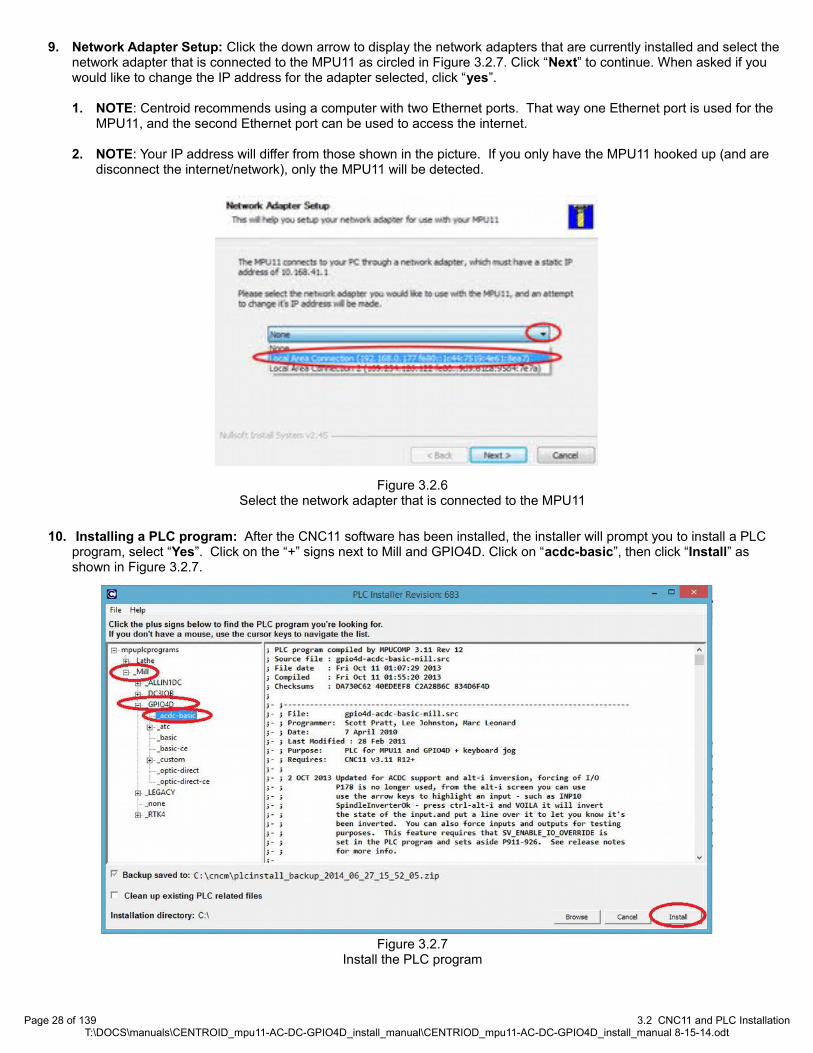
9. Network Adapter Setup: Click the down arrow to display the network adapters that are currently installed and select the network adapter that is connected to the MPU11 as circled in Figure 3.2.7. Click “Next” to continue. When asked if you would like to change the IP address for the adapter selected, click “yes”.
1. NOTE: Centroid recommends using a computer with two Ethernet ports. That way one Ethernet port is used for the MPU11, and the second Ethernet port can be used to access the internet.
2. NOTE: Your IP address will differ from those shown in the picture. If you only have the MPU11 hooked up (and are disconnect the internet/network), only the MPU11 will be detected.
10. Installing a PLC program: After the CNC11 software has been installed, the installer will prompt you to install a PLC program, select “Yes”. Click on the “+” signs next to Mill and GPIO4D. Click on “acdc-basic”, then click “Install” as shown in Figure 3.2.7.
Page 28 of 139 3.2 CNC11 and PLC InstallationT:\DOCS\manuals\CENTROID_mpu11-AC-DC-GPIO4D_install_manual\CENTRIOD_mpu11-AC-DC-GPIO4D_install_manual 8-15-14.odt
Figure 3.2.6Select the network adapter that is connected to the MPU11
Figure 3.2.7Install the PLC program

11. Click “Finish” to complete CNC11 software installation. After the PLC program installation has completed, click “Finish” to complete the installation.
12. Power off the computer, MPU11 and GPIO4D and restart.
13. Configuring Windows Firewall To Allow CNC11 to Communicate with The MPU11: The first time you run CNC11 under Windows 7, you will see a pop up window asking you if you wish to allow CNC11 to communicate with the MPU11. Check both the “Private” and “Public” check boxes, in the “Allow cncm to communicate on these networks” section and then click “Allow access” to continue. If CNC11 timed out while trying to initialize the MPU11, see Appendix A for troubleshooting.
14. Confirm that CNC11 start up correctly. Close CNC11 and continue on to the next step.
1. NOTE On wide screen monitors, CNC11 will only take up 2/3rds of the monitor screen while running in “full screen”.
Page 29 of 139 3.2 CNC11 and PLC InstallationT:\DOCS\manuals\CENTROID_mpu11-AC-DC-GPIO4D_install_manual\CENTRIOD_mpu11-AC-DC-GPIO4D_install_manual 8-15-14.odt
Figure 3.2.8Make a firewall exception

3.3 AC/DC Setup Wizard
Centroid has a motor configuration tool to simplify setting up an AC/DC. This same information is found in Technical Bulletin TB277. The latest version can be found here. (http://www.centroidcnc.com/usersupport/support_files/tbs/tb277.pdf)
The Centroid AC/DC Setup Wizard simplifies setting up an AC/DC. Alternatively, an AC/DC can be setup without using the tool by referring to the tables listed in Appendix B
1. Download the latest version of the AC/DC Motor Setup Wizard. Click on the link below to download the latest version of CNC11 software: AC/DC Motor Configuration Tool (www.centroidcnc.com/usersupport/support_files/acdc/acdc_setup_wizard.zip).
2. Extract/Decompress the downloaded file. Double click on the downloaded file. Extract the compressed file. On Windows 8 extraction is done by clicking on the “Extract all” button as shown below in Figure 3.3.1.
3. Copy and Paste into the CNCM / CNCT directory.1. Select the extracted files “ACDC Setup Wizard (.exe)” and “pwm_parameters (.xml)” 2. Copy both files as demonstrated in Figure 3.3.2.3. Right click on your CNC11 desktop shortcut. 4. Select properties as seen in Figure 3.3.35. In the shortcut tab, click on “Open File Location” as shown in Figure 3.3.4.6. Windows explorer will open up in a new window showing the contents of your CNC11 directory (The directory will be
called “CNCM” or “CNCT” depending on weather you have a mill or a lathe). Paste both files into your CNC11 directory.
Page 30 of 139 3.3 AC/DC Setup WizardT:\DOCS\manuals\CENTROID_mpu11-AC-DC-GPIO4D_install_manual\CENTRIOD_mpu11-AC-DC-GPIO4D_install_manual 8-15-14.odt
Figure 3.3.2Steps 1 & 2. Select and copy the extracted files.
Figure 3.3.3Step 3 & 4. Right click on
your CNC11 software selecting properties
Figure 3.3.4Step 5. Click “open file
location”
Figure 3.3.1Extracting the AC/DC setup wizard

4. Create a desktop shortcut.1. Highlight just the ACDC Setup Wizard (.exe) inside your CNC11 directory.2. Right click on the application. A drop down menu will come up.3. Select “Send To” on the drop down menu4. Select “Desktop (Create Shortcut)” as shown in Figure 3.3.55. Exit Windows File Explorer. On your desktop you should now have a shortcut to CNC11 and to the ACDC Setup
Wizard.
Page 31 of 139 3.3 AC/DC Setup WizardT:\DOCS\manuals\CENTROID_mpu11-AC-DC-GPIO4D_install_manual\CENTRIOD_mpu11-AC-DC-GPIO4D_install_manual 8-15-14.odt
Figure 3.3.5Creating a desktop shortcut for an application

5. Using the Centroid AC/DC Setup Wizard
1. On your desktop, double click on the ACDC Setup Wizard. The tool should looks like the figure 3.3.6 shown below. If Windows Smart Screen tries to block this program, click “more info”, then “run anyways”.
1. NOTE: Some of the information provided in the wizard is used for calculating values for unknown/unapproved motors. In this manual we will not be covering these advanced uses of the tool and can ignore the extra information.
2. Motor Configuration1. Click the large “select motor” button in the center of the screen circled in Figure 3.3.6 2. A new window will pop up. Click on the motor you are using for this axis. 3. With your motor highlighted, click “select motor” at the bottom of the screen to finalize your selection as shown in
Figure 3.3.7.
Page 32 of 139 3.3 AC/DC Setup WizardT:\DOCS\manuals\CENTROID_mpu11-AC-DC-GPIO4D_install_manual\CENTRIOD_mpu11-AC-DC-GPIO4D_install_manual 8-15-14.odt
Step 1
Step 2
Figure 3.3.6Selecting a motor
Figure 3.3.7Motor selection menu

3. Drive parameters 1. Under “Drive Parameters” use the “Drive Type” dropdown box to select your model of AC/DC as circled below in
Figure 3.3.8.2. Under “Drive Parameters” set the “Drivebus Number (LED1)” and the “Axis Number” as circled below. For the
first axis, set the Drivebus Number to 1 and the Axis Number to 1. If you have multiple AC/DCs connected together, the first axis is defined as the AC/DC that is farthest away from the MPU11. For most applications you want the drive bus number to be the same as the axis number.
3. Under “Drive Parameters” enter the motor voltage supply value in the “Bus Voltage (Vm) (VDC)” field as circled below. This is set by the output of your DC rectifier.
4. Under “CNC11 Parameters” enter your brake resistor wattage into “p284 Brake Resistor Wattage” as circled below. In most systems an AC/DC 30 will use 300 watts, and an AC/DC 60 will use 600 watts. The brake wattageis usually printed directly on the resistor.
Page 33 of 139 3.3 AC/DC Setup WizardT:\DOCS\manuals\CENTROID_mpu11-AC-DC-GPIO4D_install_manual\CENTRIOD_mpu11-AC-DC-GPIO4D_install_manual 8-15-14.odt
Step 1 Step 3Step 2
Step 4
Figure 3.3.8Entering the parameters into the AC/DC Wizard

4. Motor Parameters and General Information1. Under “Motor Parameters” enter your encoder counts in the “Encoder Counts/Rev” box as circled in Figure
3.3.9.2. Under “General Information” enter your brake resistor resistance in “Brake Resistor (ohms)” as circled below..
For most systems an AC/DC 30 is 15 Ω and an AC/DC60 is 7.5 Ω.3. Click “Calculate Parameters” as circled below.
5. Take a few seconds to review what the tool calculated. Look over all the boxes to make sure all values seem reasonable. Check for errors in any of the boxes.
1. Troubleshooting and Tips
1. If the box labeled “ACDC Current Setting (%)” says “Over 100%” the drive will still work with the AC/DC. Your motor will not run at maximum performance due to the AC/DC not being able to provide maximum powerto the drive.
2. In the unlikely event that the Wizard does encounters a “Data Missing” error, there is a box with missing information. If you get this error, contact technical support.
3. If you click on the “Window” button on the top left of the screen a menu will come up with some additional motor related tools. These tools are provided by Centroid for your convenience and are intended for advanced users.
1. “Estimate Motor Performance” will graph your motor's estimated performance using the data provided. The tool will create a graph of motor power and torque. This estimate may not be accurate on all motor types.
2. “Conversions” will convert from one unit to another
Page 34 of 139 3.3 AC/DC Setup WizardT:\DOCS\manuals\CENTROID_mpu11-AC-DC-GPIO4D_install_manual\CENTRIOD_mpu11-AC-DC-GPIO4D_install_manual 8-15-14.odt
Step 1
Step 3
Step 2
Figure 3.3.9Final parameters
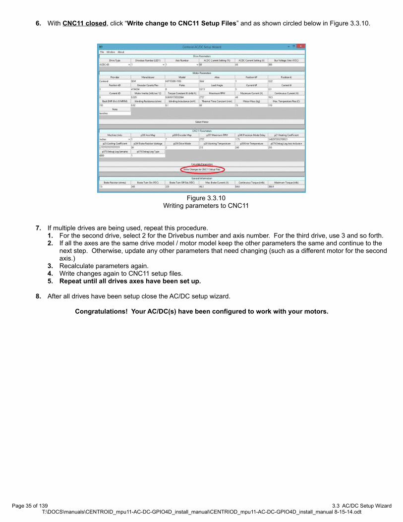
6. With CNC11 closed, click “Write change to CNC11 Setup Files” and as shown circled below in Figure 3.3.10.
7. If multiple drives are being used, repeat this procedure. 1. For the second drive, select 2 for the Drivebus number and axis number. For the third drive, use 3 and so forth.2. If all the axes are the same drive model / motor model keep the other parameters the same and continue to the
next step. Otherwise, update any other parameters that need changing (such as a different motor for the second axis.)
3. Recalculate parameters again.4. Write changes again to CNC11 setup files.5. Repeat until all drives axes have been set up.
8. After all drives have been setup close the AC/DC setup wizard.
Congratulations! Your AC/DC(s) have been configured to work with your motors.
Page 35 of 139 3.3 AC/DC Setup WizardT:\DOCS\manuals\CENTROID_mpu11-AC-DC-GPIO4D_install_manual\CENTRIOD_mpu11-AC-DC-GPIO4D_install_manual 8-15-14.odt
Figure 3.3.10Writing parameters to CNC11
CHAPTER 4 BENCH TEST
4.1 Software Configuration
Start the CNC11 Software
Troubleshooting
If you clicked on the CNC11 icon to start the software and you are getting “Timeout: MPU11 not responding” errors, you most likely didn't have the MPU11 connected to the PC when you installed the software. Check your Ethernet card to make sure it is configured properly.
Go to “Control Panel”, select “Network and Internet”, and then “Network and Sharing Center”. Click on “change adapter settings” on the upper left corner of the window, right click on the network icon, select “Properties”. Highlight “Internet Protocol Version 4 (TCP/IPv4)”, then click “Properties” again.
Select “Use the following IP address” then set the IP address and Subnet mask to:
IP address: 10.168. 41.1Subnet mask: 255.255.255.0
Click Ok and then try to start the CNC11 software again.
For more in troubleshooting see Appendices C and D.
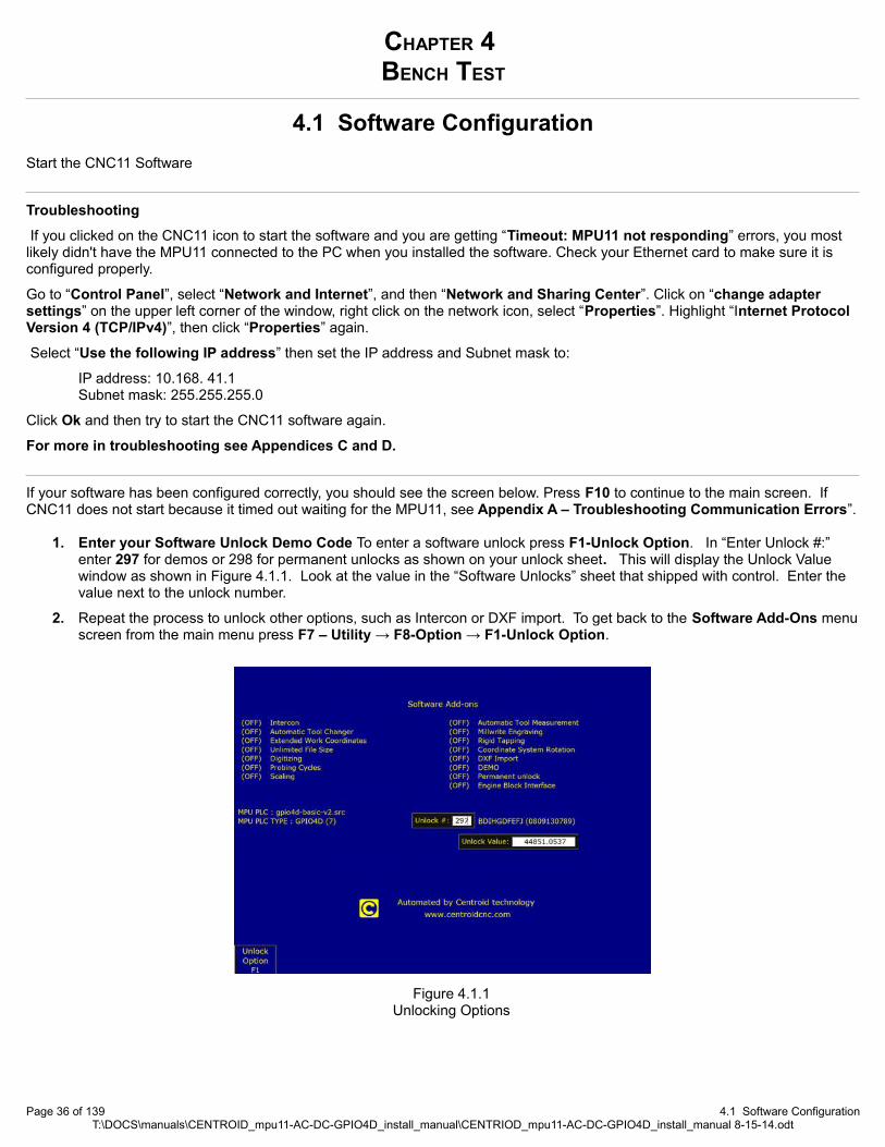
If your software has been configured correctly, you should see the screen below. Press F10 to continue to the main screen. If CNC11 does not start because it timed out waiting for the MPU11, see Appendix A – Troubleshooting Communication Errors”.
1. Enter your Software Unlock Demo Code To enter a software unlock press F1-Unlock Option. In “Enter Unlock #:” enter 297 for demos or 298 for permanent unlocks as shown on your unlock sheet. This will display the Unlock Value window as shown in Figure 4.1.1. Look at the value in the “Software Unlocks” sheet that shipped with control. Enter the value next to the unlock number.
2. Repeat the process to unlock other options, such as Intercon or DXF import. To get back to the Software Add-Ons menuscreen from the main menu press F7 – Utility → F8-Option → F1-Unlock Option.
Page 36 of 139 4.1 Software ConfigurationT:\DOCS\manuals\CENTROID_mpu11-AC-DC-GPIO4D_install_manual\CENTRIOD_mpu11-AC-DC-GPIO4D_install_manual 8-15-14.odt
Figure 4.1.1Unlocking Options

From now on when using CNC11, you can always go up one menu level by pressing the escape key (ESC). Tapping escape multiple times from any menu will eventually take you back to the main menu.
To do the bench testing temporarily disable the fault protection logic built into CNC11 and the PLC program as specified inthe following pages. CNC11 monitors the signal levels of hardware as jog panels and encoder inputs, and will generate a fault if any hardware does not respond as expected. In addition, the ACDC-basic PLC program contains default logic that monitors the inputs for Limit Switches (inputs 1-8), Lube Fault (input 9), Spindle Fault (input 10), Estop (input 11), and AxisDrive Faults (inputs 17-20). If ANY of these inputs are open a fault will be issued.
3. Change Machine Home Type To navigate to the “Control Configuration” screen. From the main screen press press F1-Setup → F3 -Config. The password is 137. Then press F1 Contrl. Using the keyboard spacebar change “Machine home at power up” to “Jog”.
1. TIP If you can not save any of your changes in CNC11, close CNC11. Right click on CNC11 desktop shortcut. Selectproperties. Click on the Compatibility tab. Check the box labeled “Run this program as an administrator”. Click “Apply”. Click “OK”. Start CNC11 again.
4. Disable Jog Panel Communication Faults (If you have a jog panel or pendant connected, skip this step.) If the optional Jog Pendant is not connected for bench testing, disable Jog Panel communication faults. Use the arrow keys to select “Jog Panel Required” in the Control Configuration and press the space bar to toggle to “No”.
Press F10-SAVE to save. After Saving, Press escape to go back to the Main Screen. Press F10-Shutdown, → F2 Power Off, and then power off the MPU11 and GPIO4D via switching of your outlet strip. Wait 30 seconds and power everything back up.
Page 37 of 139 4.1 Software ConfigurationT:\DOCS\manuals\CENTROID_mpu11-AC-DC-GPIO4D_install_manual\CENTRIOD_mpu11-AC-DC-GPIO4D_install_manual 8-15-14.odt
Figure 4.2.2Changing machine home at powerup to disable limit switches
Figure 4.1.3Disabling jog panel

5. Disable PLC faults for Limit Switches, Lube, Spindle, Estop and Axis Faults. At the main screen press the alt and i keys to bring up the real-time I/O display as shown in Figure 4.1.4. Using the arrow keys, move the selection box to the top left of the inputs. The screen should read “INP1 Ax1_MinusLimitOk” as circled below. Press the ctrl alt and i keys simultaneously to invert this input.
You will notice that the LED will turn from red to green and a line will be drawn over the top to indicate that it the state of the input has been programmatically inverted. Repeat the process until inputs 1-11 and inputs 17-20 are green as shown below.
1. NOTE: Using alt + I to disable I/O only works for those using the default Centroid provided PLC programs. On a custom PLC program, this feature may need to be added to the PLC code.
6. Label the Axes: From the main menu, press F1-Setup → F3 -Config. The password is 137. Press F2 Mach. → F2 Motor. Under “Label” configure the software for the correct number of axes and label them appropriately. Any unused axes should be set to “N” to disable the axis as seen in Figure 4.1.5.
Page 38 of 139 4.1 Software ConfigurationT:\DOCS\manuals\CENTROID_mpu11-AC-DC-GPIO4D_install_manual\CENTRIOD_mpu11-AC-DC-GPIO4D_install_manual 8-15-14.odt
Figure 4.1.4Disabling inputs using alt + i
Figure 4.1.5Labeling the axses and verifying the spindle axis.
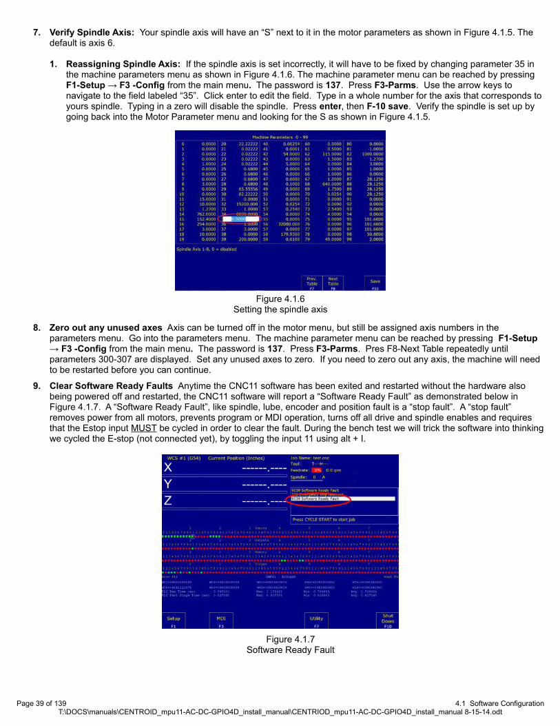
7. Verify Spindle Axis: Your spindle axis will have an “S” next to it in the motor parameters as shown in Figure 4.1.5. The default is axis 6.
1. Reassigning Spindle Axis: If the spindle axis is set incorrectly, it will have to be fixed by changing parameter 35 in the machine parameters menu as shown in Figure 4.1.6. The machine parameter menu can be reached by pressing F1-Setup → F3 -Config from the main menu. The password is 137. Press F3-Parms. Use the arrow keys to navigate to the field labeled “35”. Click enter to edit the field. Type in a whole number for the axis that corresponds toyours spindle. Typing in a zero will disable the spindle. Press enter, then F-10 save. Verify the spindle is set up by going back into the Motor Parameter menu and looking for the S as shown in Figure 4.1.5.
8. Zero out any unused axes Axis can be turned off in the motor menu, but still be assigned axis numbers in the parameters menu. Go into the parameters menu. The machine parameter menu can be reached by pressing F1-Setup → F3 -Config from the main menu. The password is 137. Press F3-Parms. Pres F8-Next Table repeatedly until parameters 300-307 are displayed. Set any unused axes to zero. If you need to zero out any axis, the machine will need to be restarted before you can continue.
9. Clear Software Ready Faults Anytime the CNC11 software has been exited and restarted without the hardware also being powered off and restarted, the CNC11 software will report a “Software Ready Fault” as demonstrated below in Figure 4.1.7. A “Software Ready Fault”, like spindle, lube, encoder and position fault is a “stop fault”. A “stop fault” removes power from all motors, prevents program or MDI operation, turns off all drive and spindle enables and requires that the Estop input MUST be cycled in order to clear the fault. During the bench test we will trick the software into thinkingwe cycled the E-stop (not connected yet), by toggling the input 11 using alt + I.
Page 39 of 139 4.1 Software ConfigurationT:\DOCS\manuals\CENTROID_mpu11-AC-DC-GPIO4D_install_manual\CENTRIOD_mpu11-AC-DC-GPIO4D_install_manual 8-15-14.odt
Figure 4.1.6Setting the spindle axis
Figure 4.1.7Software Ready Fault

To clear a stop fault, press the alt-i keys to bring up the real-time I/O screen, use the arrow keys to select the “EstopOk input(11)” as shown below in Figure 4.1.8. Press the ctrl-alt-i keys simultaneously to toggle the EstopOK input to red, and press the crtl-alt-i keys again to toggle it back to green.
Notice that as you toggle the EstopOk input to red “406 Emergency Stop Detected” is displayed in the status window as shown above in Figure 4.1.9. When the emergency stop is pressed notice how “2099 Message Cleared” is displayed, referring to clearing the “9039 stop fault”. Toggling EStopOK back to green displays “335 Emergency Stop Released”.
10. Clear Any Existing Faults Before Beginning Bench Testing. To confirm that all faults have been cleared before continuing, press F3 MDI from the main menu. If all faults have been cleared correctly, the screen should look like Figure 4.1.10.
If the screen shown in Figure 4.1.10 is not displayed, there is an existing fault. Please check the status window to determine the cause of the fault and then clear it as shown in Figure 4.1.8. Confirm that all parameters are set as required and that all inputs (1-11 & 17-20 green) are in the correct state.
All faults shown in Figure 4.1.11 (as well as other faults) are “Stop Faults”. Stop faults cancel existing jobs, prevent new jobs from being started, stop the spindle, prevent motion, and require that the E stop PLC input be cycled (opened and closed) in order to clear the fault before continuing.
If you have any stop faults, they will have to be removed then E-stop will have to be toggled as shown in the previous step.
Page 40 of 139 4.1 Software ConfigurationT:\DOCS\manuals\CENTROID_mpu11-AC-DC-GPIO4D_install_manual\CENTRIOD_mpu11-AC-DC-GPIO4D_install_manual 8-15-14.odt
Figure 4.1.11 Faults detected
Figure 4.1.10MDI Command Mode
Figure 4.1.8Toggling E-stop
Figure 4.1.9Status window showing the emergency
stop clearing faults.
4.2 Bench Testing the AC/DC
Since the AC/DC is a drive, there is not a lot of I/O testing we can do. Primarily we want to test drive communication with the MPU11 and encoder communication with the drive.
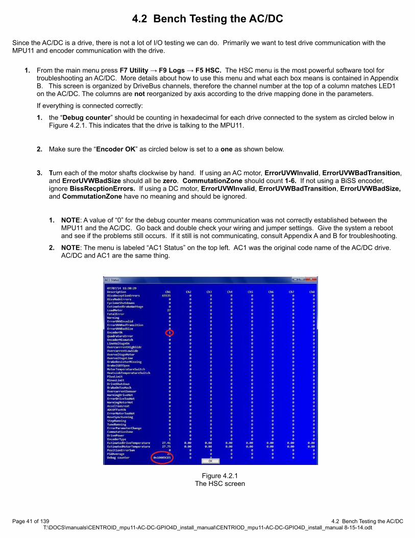
1. From the main menu press F7 Utility → F9 Logs → F5 HSC. The HSC menu is the most powerful software tool for troubleshooting an AC/DC. More details about how to use this menu and what each box means is contained in Appendix B. This screen is organized by DriveBus channels, therefore the channel number at the top of a column matches LED1 on the AC/DC. The columns are not reorganized by axis according to the drive mapping done in the parameters.
If everything is connected correctly:
1. the “Debug counter” should be counting in hexadecimal for each drive connected to the system as circled below in Figure 4.2.1. This indicates that the drive is talking to the MPU11.
2. Make sure the “Encoder OK” as circled below is set to a one as shown below.
3. Turn each of the motor shafts clockwise by hand. If using an AC motor, ErrorUVWInvalid, ErrorUVWBadTransition,and ErrorUVWBadSize should all be zero. CommutationZone should count 1-6. If not using a BiSS encoder, ignore BissRecptionErrors. If using a DC motor, ErrorUVWInvalid, ErrorUVWBadTransition, ErrorUVWBadSize, and CommutationZone have no meaning and should be ignored.
1. NOTE: A value of “0” for the debug counter means communication was not correctly established between the MPU11 and the AC/DC. Go back and double check your wiring and jumper settings. Give the system a reboot and see if the problems still occurs. If it still is not communicating, consult Appendix A and B for troubleshooting.
2. NOTE: The menu is labeled “AC1 Status” on the top left. AC1 was the original code name of the AC/DC drive. AC/DC and AC1 are the same thing.
Page 41 of 139 4.2 Bench Testing the AC/DCT:\DOCS\manuals\CENTROID_mpu11-AC-DC-GPIO4D_install_manual\CENTRIOD_mpu11-AC-DC-GPIO4D_install_manual 8-15-14.odt
Figure 4.2.1The HSC screen

2. Press the Estop button in keep it depressed. Go back to the main menu. From the main menu press F1 -Setup → F3 Config. The password is 137. Press enter → F4 PID. This will display the PID menu screen below and allow you to monitor the encoder counts by watching the values in “Abs Pos” field (circled below in Figure 4.2.2) for each axis.
7.5 To confirm that each encoder is wired correctly, rotate the motor shaft Clockwise (as seen while looking at the face of the motor as shown below) and confirm that the counts displayed in the ABS Pos column of the PID menu change. For a DC brushed motor the absolute position value should decrease. For a brushless motor the absolute position should increase.
Record how much the motor counts during one revolution. Go into the motor parameters menu. From the main menu, press F1-Setup → F3 -Config. The password is 137. Press F2 Mach. → F2 Motor. The encoder counts/rev field (circled below in Figure 4.2.4) should approximately match how much the encoder counted when it was turned one revolution.
Page 42 of 139 4.2 Bench Testing the AC/DCT:\DOCS\manuals\CENTROID_mpu11-AC-DC-GPIO4D_install_manual\CENTRIOD_mpu11-AC-DC-GPIO4D_install_manual 8-15-14.odt
Figure 4.2.2Watching absolute position of the PID menu
Figure 4.2.3Rotate the motor clockwise
Figure 4.2.4Encoder counts per revolution
4.3 Bench Testing the MPU11 and GPIO4D
Bench testing the MPU11 and GPIO4D will confirm that the MPU11 and GPIO4D are operational and that the software has been properly configured to begin the installation process. Bench Testing is required as it provides a known base configuration that our support engineers can refer to when trying to diagnose any issues that may have arisen. To complete Bench Testing, a USB thumb drive and DVM (Digital Volt Meter) is required.
1. Set Home and load spindlebenchtest.cnc: From the main menu press F2-Load. Use the arrow keys to select the file spindlebenchtest.cnc
1. If spindlebenchtest.cnc is not present in the c:\cncm\ncfiles directory it can be downloaded here: spindle benchtest.cnc (http://centroidcnc.com/usersupport/support_files/benchtest/ spindle benchtest.cnc)
2. Download spindlebenchtest.cnc. If your web browser does not provide an option to download spindlebenchtest.cnc and instead displays a bunch of code, copy the code from your web browser into your default text editor (such as notepad++). Save the file as spindlebenchtest.cnc.
3. Copy spindlebenchtest.cnc to your CNC11 root directory.
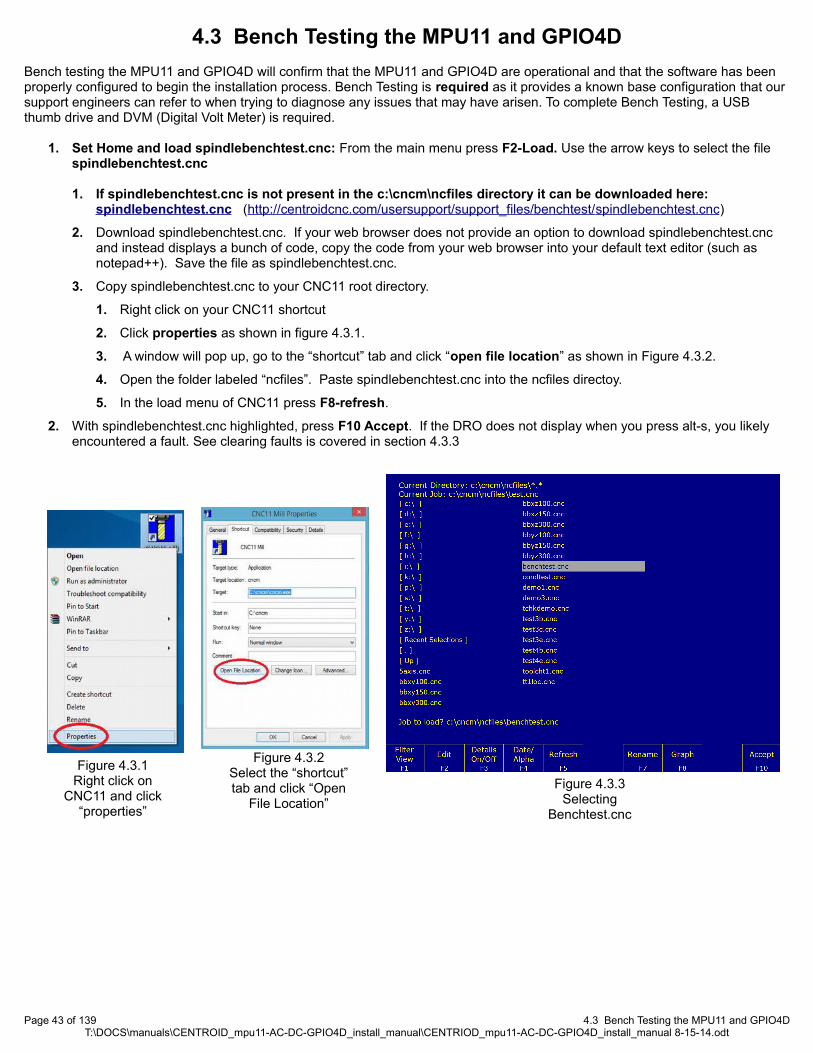
1. Right click on your CNC11 shortcut
2. Click properties as shown in figure 4.3.1.
3. A window will pop up, go to the “shortcut” tab and click “open file location” as shown in Figure 4.3.2.
4. Open the folder labeled “ncfiles”. Paste spindlebenchtest.cnc into the ncfiles directoy.
5. In the load menu of CNC11 press F8-refresh.
2. With spindlebenchtest.cnc highlighted, press F10 Accept. If the DRO does not display when you press alt-s, you likely encountered a fault. See clearing faults is covered in section 4.3.3
Page 43 of 139 4.3 Bench Testing the MPU11 and GPIO4DT:\DOCS\manuals\CENTROID_mpu11-AC-DC-GPIO4D_install_manual\CENTRIOD_mpu11-AC-DC-GPIO4D_install_manual 8-15-14.odt
Figure 4.3.1Right click on
CNC11 and click “properties”
Figure 4.3.2Select the “shortcut” tab and click “Open
File Location”
Figure 4.3.3Selecting
Benchtest.cnc

Testing the analog output for the spindle: The GPIO4D provides a 0 to +10VDC analog output to provide programmable spindle speed control using a VFD (variable frequency drive). The default maximum spindle speed specified in the Control Configuration is 3000rpm. This configures the control to scale the 0 to +10VDC from 0-3000rpm. A spindle speed command of S1500 will therefore output +5VDC, a command of S1000 will output +3.33VDC and so on.
Page 44 of 139 4.3 Bench Testing the MPU11 and GPIO4DT:\DOCS\manuals\CENTROID_mpu11-AC-DC-GPIO4D_install_manual\CENTRIOD_mpu11-AC-DC-GPIO4D_install_manual 8-15-14.odt
1. Set a digital voltage meter to VDC as shown in Figure 4.4.4.
2. Insert the digital voltage meter leads into H6 as shown in Figure 3.9.4. Tighten down the screw terminals to firmly grip the probes.
3. With benchtest.cnc loaded, press Cycle start (alt-s) to begin. The following screen will be displayed: (You may have to press Cycle start twice)
4. Enter the voltage readings as pictured, and press Cycle start to continue.
Probe Terminals Here
Figure 4.3.4Selecting
Benchtest.cnc

CHAPTER 5ELECTRICAL CABINET INSTALLATION
5.1 Introduction to Electrical Cabinet Layout
Now that you are finished with the board level test it is time to think about electrical cabinet installation. In this chapter of the manual we will go into detail about how to wire the various systems into your cabinet. Below is a sample AC/DC electrical cabinet from Centroid in the final stages of wiring. (Note: some of the wiring in the picture below is in the process of being added). During cabinet wiring it is important that you follow the schematic provided by Centroid. The following page and the picture below outlinesome basic best practices.
Page 45 of 139 5.1 Introduction to Electrical Cabinet LayoutT:\DOCS\manuals\CENTROID_mpu11-AC-DC-GPIO4D_install_manual\CENTRIOD_mpu11-AC-DC-GPIO4D_install_manual 8-15-14.odt
Single grounding bar
Leave two inches of space
Label all wires, devices, relays, etc.
High voltage AC power lines kept away from low voltage signal lines.
Figure 5.1.1Sample Electrical Cabinet

• Minimize Noise and Interference
◦ Keep sensitive electronics away from noisy equipment. Install high voltage drives, rectifiers, transformers, contactors, and other electrically noisy equipment as far away from low voltage circuit boards (such as the MPU11 or GPIO4D) as practical.
◦ Keep high voltage power lines far away from low voltage signal lines. Keep the high-voltage AC power lines andmotor power lines as far away from low voltage logic signals as practical.
◦ Grounding Principle. Wire the incoming chassis ground lug directly to a single ground bus bar as shown in the picture on the previous page. Wire all cabinet doors, AC/DC chassis grounds, power supply chassis ground, and other equipment chassis ground to one single ground bus bar. What you should NOT do is have several different grounding points throughout the cabinet, as this could increase electrical noise and interference.
◦ Leave plenty of space between wire ducts and components. Keep wire ducts at least 2” away from components when practical.
◦ Use Snubbers on Contactors. Contactor blocks and relays need a snubber across the coil. Centroid recommends using Quencharc snubber networks (Centroid PART# 1819). This reduces electrical noise. If you are new to using snubbers more information can be found in Technical Bulletin #206, the latest version can be found here.(http://www.centroidcnc.com/usersupport/support_files/tbs/tb206.pdf)
• Keep the cabinet maintainable and easily serviceable. Centriod can provide electrical cabinet materials such as contactors blocks, time delay contactor blocks, relays, fuse blocks, din rails, overload relay with fuses, din rail end stops, terminal blocks, etc. Call Centroid for details.
◦ Wire management Use PVC wire ducts (such as Panduit Panduct) to keep your wires neat and organized.
◦ Use DIN Rails Use DIN rails for mounting relays, contactors, terminal blocks, circuit protection blocks, disconnects, etc.
◦ Leave a little bit of slack in the wire. Take all corners in the wiring ducts as wide as possible. Always leave a little bit of slack in the wires.
◦ Keep all the wiring in neat horizontal and vertical lines.
◦ Label EVERYTHING. Label everything so that it matches the labels on your schematic. This includes labeling each individual wire at both ends, circuit boards, relays, contactors, etc.
◦ Don't lose the schematic. Keep the schematic attached to the cabinet somewhere so it doesn't get lost.
• Use the correct AWG Below is the minimum AWG for the AC/DC.
Minimum Wire Gauge (AWG)[1]
Motor Power Cable Vm+, Vm- Brake+, Brake- Logic PowerAC/DC-30 16 14 16 16
AC/DC-60 12 10 12 161. Recommendations for typical applications – cable lengths, drive current setting, and motor loads may change requirements. Always follow the electrical code.
Page 46 of 139 5.1 Introduction to Electrical Cabinet LayoutT:\DOCS\manuals\CENTROID_mpu11-AC-DC-GPIO4D_install_manual\CENTRIOD_mpu11-AC-DC-GPIO4D_install_manual 8-15-14.odt

Common Wiring Problems
The following information is also covered in Technical Bulletin #78 which can be found here. (http://www.centroidcnc.com/usersupport/support_files/tbs/tb078.pdf)
Page 47 of 139 5.1 Introduction to Electrical Cabinet LayoutT:\DOCS\manuals\CENTROID_mpu11-AC-DC-GPIO4D_install_manual\CENTRIOD_mpu11-AC-DC-GPIO4D_install_manual 8-15-14.odt
Figure 5.1.2Common Wiring Problems

5.2 Electrically Configuring Inputs on the GPIO4D
The inputs of the GPIO4D can be configured for either 5, 12, or 24 volts DC. The input voltage is changed by changing the resistance of the SIP (single inline package) resistor. By default the GIO4Ds come with SIPs for 24VDC installed. If you are usinga voltage other than 24VDC, the SIPs need to be changed.
The SIP resistance is the defined by the last three numbers of the manufacturers part number as shown in Figure 5.2.1. Of the last three numbers, the first two digits signify the value of the resistance. The last digit signifies the number of zeros after the value. For example if the manufacturers part number is “4308R-102 LF – 222”, the values 222 define the resistance. The resistance is 22 plus two zeros, so the final value is 2200 Ohms. The chart next to Figure 5.2.1 defines which resistors are needed for which voltages.
Voltage Level Centriond SIPPart #
SIP Value
5VDC 3950 470 Ohm(471)
12VDC 4152 1K Ohm(102)
24VDC(default)
1548 2.2K Ohm(222)
Looking closely at the GPIO4D, the silkscreen is labeled “SIP1, SIP2, SIP3, and SIP4” as shown in Figure 5.2.2. Each SIP controls a group of I/O as demonstrated by the table below.
Input Group SIP Number
Inputs 1-4 4
Inputs 5-8 3
Inputs 9-12 2
Inputs 13-16 1
Page 48 of 139 5.2 Electrically Configuring Inputs on the GPIO4DT:\DOCS\manuals\CENTROID_mpu11-AC-DC-GPIO4D_install_manual\CENTRIOD_mpu11-AC-DC-GPIO4D_install_manual 8-15-14.odt
Figure 5.2.1Reading SIPs
Figure 5.2.2Location of SIPs

All inputs on the GPIO4D can be configured for sourcing or sinking operation using either 5VDC, 12 or 24 VDC. The inputs are arranged in groups of four with a common shared by each input in a group.
There are two ways to wire I/O on the GPIO4D:
• Sourcing Connecting the inputs to power is sourcing. The netagive lead of the power supply must be connected to common. This is demonstrated on inputs 1-4 in Figure 5.2.3.
• Sinking By connecting the inputs to ground is sinking. The positive lead of the power supply must be connected to common. This is demonstrated on inputs 5-8 in Figure 5.2.3
Page 49 of 139 5.2 Electrically Configuring Inputs on the GPIO4DT:\DOCS\manuals\CENTROID_mpu11-AC-DC-GPIO4D_install_manual\CENTRIOD_mpu11-AC-DC-GPIO4D_install_manual 8-15-14.odt
IN1 IN2 IN3 IN4
COM 1-4 IN5 IN6 IN7
IN8 COM 5-8
+12VDC
+12VDC
+12VDC
12VCOM
GPIO4D Board
Figure 5.2.3Wiring Limit
Switches 12VCOM

5.3 Wiring Motors
The AC/DC supports over 60 different motors. Including over 50 different Fanuc motors, 6 SEM motors, and 4 Mecapian motors. The easiest way to install an AC/DC is with motors provided by Centroid. Users should only use motors on the list of motors foundin Appendix G. What if your motors not on the list? For an evaluation fee, Centroid can evaluate your motor and provide you withthe correct software parameters.
In the future, Centroid plans on bringing an advanced set of features to the Centroid CNC11 software, allowing users to calculate their own software parameters without the need to have Centroid evaluate their motors.
Motor Installation Procedure
1. On the motor, check for >100 MΩ between the motor chassis, and the motor power terminals.
2. On the AC/DC drive, check for >100 MΩ between the motor chassis and the power terminals.
3. Wire the motors to the drive.
1. 16 AWG minimum is required for the AC/DC 30. 12 AWG minimum is required for the AC/DC 60.
2. For AC motors connect the U, V, and W to the corresponding terminals of the AC/DC. For DC motors connect the negative wire to the V terminal and the positive wire to the W terminal as shown below in Figure 5.3.1.
3. Ground the motor power cable to the AC/DC Chassis as shown below in Figure 5.3.1.
4. With the motors connected, confirm continuity between motor chassis and the AC/DC chassis using a DVM/multimeter.
1. DANGER An ungrounded motor is an electrocution hazard. Always confirm continuity with a multimeter!
Page 50 of 139 5.3 Wiring Motors T:\DOCS\manuals\CENTROID_mpu11-AC-DC-GPIO4D_install_manual\CENTRIOD_mpu11-AC-DC-GPIO4D_install_manual 8-15-14.odt
Figure 5.3.1AC and DC motor Wiring

5.4 Wiring AC/DC Brake Resistor
A motor acts like a generator when it is trying to slow down. The AC/DC slows the motor by converting unwanted electricity into heat using a brake resistor. Therefore, the brake resistor gets extremely hot and can run over 65C or 150F.
Centroid recommends installing the brake resistor outside the electrical cabinet, but always consult with your local electricalcode first and be sure to follow any safety requirements. Care must be taken to ensure that the brake resistor gets adequate air flow, and does not overheat the electrical cabinet or pose a burn hazard. Always keep the electrical cabinet below 40°C (104°F). A guard can be fabricated around the brake resistor if needed to prevent accidental burns.
Brake resistors are NOT polarity sensitive.
Centroid recommends using two 300 watt 15 ohm brake resistors (Part Number 7352) in parallel for an AC/DC60, and one 300 watt 15 ohm brake resistor (Part Number 7352) for an AC/DC 30. 12 AWG minimum is required for an AC/DC60, and 16 AWG minimum is required for an AC/DC-30.
Page 51 of 139 5.4 Wiring AC/DC Brake ResistorT:\DOCS\manuals\CENTROID_mpu11-AC-DC-GPIO4D_install_manual\CENTRIOD_mpu11-AC-DC-GPIO4D_install_manual 8-15-14.odt

5.5 Wiring E-Stop(refer to the picture on the next page)
1. E-Stop Wiring The E-stop is a safety mechanism used to shut off the machine during an emergency. The switch should be closed when the machine is in it's operational state. Wiring E-stop in a normally open configuration is dangerous as it will not stop the machine in the event that a wire breaks. It also prevents noise from causing spurious faults because the signal is being electrically held at the operational level.
1. E-Stop Switch – Use a double pole single throw (DPST), normal closed, twist to release, emergency stop switch. Such as Centroid part number #1009 used with #5934.
2. GPIO4D E-Stop - Input 11 needs to be routed through your E-stop switch so the PLC knows if the E-stop is engaged.The coil voltage that controls the Estop contactor is routed through two sets of fault relays on the GPIO4D. The Estopswitch and fault relays are wired in series so that, if any of the circuits is opened the Estop contactor is dropped out.
1. The first relay, Output1, is controlled by the PLC program. It can be used to drop the Estop contractor based on any PLC event.
2. The second relay, Output17, is used to drop the Estop contractor in the event that a fault occurs that the PLC is not be able to recognize – such as a hardware communication error between the GPIO4D and the MPU11.
3. AC/DC E-Stop - Wire the AC/DC E-stop relay in series with the GPIO4D E-stop relay as shown on the next page. Treat CN1 (pin 2) as your E-Stop input for the AC/DC, and CN2 (pin1) as your E-stop output for the AC/DC. This allows the AC/DC to cut the power to the motors in the event of a fault, even if they have lost communication with the MPU11 and GPIO4D.
4. Contactor – A snubber needs to be placed across the contactor(s). Centroid recommends using Quencharc snubber networks (Centroid PART# 1819). This reduces electrical noise when the motor power is cycled on and off.
5. Voltages
1. GPIO4D Inputs – The example on the next page uses +12VDC for input 9. This voltage can be 5 to 24 VDC depending on the SIPs used in the GPIO4D as demonstrated in section 4.2
2. GPIO4D and AC/DC Relay Outputs – In the example on the next page 24VAC is used for the relays. The relay outputs on the AC/DC and GPIO4D are rated for up to 30 VDC @ 5 amps OR up to 125 VAC @ 10 Amps. It is best practice to use lowest practical voltage with your relays, as higher voltages create more electrical noise and interference.
2. Testing E-Stop Wiring
1. Power up your system.2. Start CNC11 and press F10 to continue to the main screen3. Enable the E-stop (which was inverted during board level testing). In the main menu press alt + I to bring up the real
time I/O display. 4. Click on input 11.5. Press the ctrl-alt-i keys simultaneously to remove the bar over the input in the display, enabling your E-stop.6. Toggle the E-stop. Confirm that input 11 is green when the E-stop is released (not tripped).
Page 52 of 139 5.5 Wiring E-StopT:\DOCS\manuals\CENTROID_mpu11-AC-DC-GPIO4D_install_manual\CENTRIOD_mpu11-AC-DC-GPIO4D_install_manual 8-15-14.odt

Example E-Stop Wiring
Page 53 of 139 5.5 Wiring E-StopT:\DOCS\manuals\CENTROID_mpu11-AC-DC-GPIO4D_install_manual\CENTRIOD_mpu11-AC-DC-GPIO4D_install_manual 8-15-14.odt
Figure 5.5.1E-Stop Wiring

5.6 Wiring Limit Switches
All inputs used for Limit switches must be wired in normally closed configuration. The switch should be closed when the machine is in its operational state. Wiring any of these inputs in a Normally Open configuration is dangerous as the machine will not stop in the event that a wire breaks. It also prevents noise from causing spurious faults because the signal is being electrically held at the operational level.
The I/O configuration on every machine is different. While the examples below assume dry contact type switches and utilize 12VDC, your machine may utilize different voltage levels and different type devices devices such NPN, or PNP proximity sensors. If your devices are proximity sensors, they MUST be 3-wire sensors, 2-wire sensors will not work reliably. Make sure the SIPS you installed in section 4.2 match the voltage levels for your devices.
Failure to install the proper SIPS to match the voltage levels being used will damage the GPIO4D. Do not use the limit switch I/O on the AC/DC. At the time of this writing, they are not supported.
Connect your limit switches as shown below in Figure 5.6.2.
Testing Limit Switch Wiring
1. Power up your system.2. Start CNC11 and press F10 to continue to the main screen3. Invert the limit switches (which were inverted during board level testing). In the main menu press alt + I to bring up the
real time I/O display. 4. Click on limit switch inputs (input 1 - 8), and press the ctrl-alt-i keys simultaneously to remove the bar over the input in
the display. This will enable your limit switches.5. Confirm that all limit switches are are green when nothing is tripped. Confirm that the correct input turns red when the
switch is tripped.
Page 54 of 139 5.6 Wiring Limit SwitchesT:\DOCS\manuals\CENTROID_mpu11-AC-DC-GPIO4D_install_manual\CENTRIOD_mpu11-AC-DC-GPIO4D_install_manual 8-15-14.odt
IN1 IN2 IN3 IN4
COM 1-4 IN5 IN6 IN7
IN8 COM 5-8 12COM
12VCOM
+12VDC
GPIO4D Board
IN9IN10IN11IN12
COM 9-12 IN13
IN14IN15
IN16COM13-16 12COM
12VCOM
+12VDC
X- LimitX+ LimitY- LimitY+ Limit
Z- LimitZ+ LimitW- LimitW+ Limit
Figure 5.6.1Do not use AC/DC limit switches.
Figure 5.6.2AC/DC limit switches.

5.7 Wiring Lube Pump(refer to the picture on the next page)
The typical lube pump circuit consists of two parts: The first part is the control of the lube pump itself which is controlled by output2 sending 110VAC to the lube pump. The second part is the low lube alarm signal which gets wired to input 9. The low lube signal tells the control to produce a “405 Low lube” alarm which inhibits the control from starting a new job until the lube pump is refilled and the alarm is cleared.
Keep in mind that the GPIO4D output relay is rated for up to 5 amps DC or 10 Amps AC. If your lube pump draws more current you will need to install a contactor.
When wiring your lube pump it is important to know which type of lube pump you have so that you configure it correctly. Typically lube pumps come in one of 3 types:
• Mechanical Cam Actuated Lube Pump: This pump is based on a simple mechanical plunger riding on a clock motor driven cam. The advantage of this type of lube pump is that it is reliable and it remembers where it was and how much runtime has been accumulated even between power cycles. So that you actually get lube every 10 minutes for 5 seconds of machine use.
• Electronic Lube Pumps: These pumps try to imitate the mechanical cam pumps but often forget where in sequence they were when powered off. There are two types of Electronic lube pumps, “lube first” which pumps lube immediately after power on. Which typically results in too much lube. The second type is “lube last”, this type waits a set amount of time before lubing the machine. The problem with this type is on small jobs your machine may never get any lube, therefore possibly damaging the machine. To avoid this some people wire the lube last type to get power all the time which then results in too much lube.
• Direct controlled lube pumps: These pumps are controlled by the control via the PLC program and the software. With this type the lube pump is not responsible for the timing of the pump actuation. This method is the best for reliable, even lubing of your machine. Centroid Users see Tech Bulletin #171 and Parameter 179 in the operators manual for further explanation.
Enabling Lube Inputs
1. Power up your system.2. Start CNC11 and press F10 to continue to the main screen3. Invert the lube fault input (which was inverted during board level testing). In the main menu press alt + I to bring up
the real time I/O display. 4. Click on input 9, and press the ctrl-alt-i keys simultaneously to remove the bar over the input in the display. This will
enable your lube fault input.5. Confirm that lube fault is green when nothing is tripped. Confirm that the correct input turns red when the switch is
tripped.
Page 55 of 139 5.7 Wiring Lube PumpT:\DOCS\manuals\CENTROID_mpu11-AC-DC-GPIO4D_install_manual\CENTRIOD_mpu11-AC-DC-GPIO4D_install_manual 8-15-14.odt

Page 56 of 139 5.7 Wiring Lube PumpT:\DOCS\manuals\CENTROID_mpu11-AC-DC-GPIO4D_install_manual\CENTRIOD_mpu11-AC-DC-GPIO4D_install_manual 8-15-14.odt
Figure 5.7.1Sample Lube Pump Circuit

5.8 Wiring Coolant Pump
By default GPIO4D output 3 is the coolant flood pump output and output 4 is the default output for a coolant mist pump. If you have a custom PLC program your I/O may be different.
This sub-circuit shows how to hook up a 3 phase Flood Pump. Because the pump in this example draws more power than the GPIO4D is rated for, a Flood Contactor (Centroid PART# 3959) is needed.
All contactors need a snubbers. Centriod recommends using the Quencharc snubber network (Centroid PART# 1819) on the coil of the contactor. This reduces electrical noise when flood coolant is cycled on and off. A thermal overload is also shown, this part protects the motor by opening the circuit if it stalls for any reason, such as metal chips in the pump.
Centroid recommends a thermal overload protector. The example below diagram depicts the 24VAC wired through the NC contacts on the overload section of the contactor. The overload protection circuit on your existing contactor may be labeled differently or there may be no overload protection.
Page 57 of 139 5.8 Wiring Coolant PumpT:\DOCS\manuals\CENTROID_mpu11-AC-DC-GPIO4D_install_manual\CENTRIOD_mpu11-AC-DC-GPIO4D_install_manual 8-15-14.odt
Figure 5.8.1Sample Coolant Pump Circuit

5.9 Wiring Spindle
More information on spindle can be found in Technical Bulletin #152, which can be found here. (http://www.centroidcnc.com/usersupport/support_files/tbs/tb152.pdf)
STOP: Before wiring up the spindle make sure that you already tested the spindle as directed during the board level tests.
There are two methods of wiring a spindle:
1. Connect three phase directly to an induction motor (shown on the next page). Hooking the three phase directly saves costs, but prevents the Centriod CNC software from being able to control the speed of the spindle. The spindle speed will have to be controlled by mechanical methods such as pulleys.
2. Use a spindle controller (not shown). The terms “inverter” (short for power inverter), “AC Drive”, and “VFD” (Variable Frequency Drive) can all refer to the spindle controller. Centroid does not provide spindle controllers and recommends using Delta Products VFDs, Automation Direct GS2 and GS3 AC drives, as well as Yaskawa VS (Varispeed) Inverters. It is the responsibility technician installing to consult their spindle controller manufacturer for support. However, Centroid does provide Technical Bulletins with detailed installation instructions and troubleshooting for a few select models of spindle controllers.
With the default PLC program, several of the I/O are decided for use with a spindle. Input 10 is the spindle fault input. Output 7 is the spindle fault output. Output 5 is the inverter fault reset. Output 8 is the inverter direction. Output 10 is for a spindle cooling fan. Always refer to your schematic.
In the example below the thermal overload protector is wired directly to the spindle fault. If your spindle controller has a fault condition it should be wired in series with the thermal overload protector.
All contactors need snubbers. Centriod recommends using the Quencharc snubber network (Centroid PART# 1819) on the coil of the contactor. This reduces electrical noise when the spindle is turned off and on.
Enabling Spindle Fault Inputs
1. Power up your system.2. Start CNC11 and press F10 to continue to the main screen3. Invert the spindle fault input (which was inverted during board level testing). In the main menu press alt + I to bring up
the real time I/O display. 4. Press the ctrl-alt-i keys simultaneously to remove any bars over the input in the display. This will enable the spindle
inputs.
Page 58 of 139 5.9 Wiring SpindleT:\DOCS\manuals\CENTROID_mpu11-AC-DC-GPIO4D_install_manual\CENTRIOD_mpu11-AC-DC-GPIO4D_install_manual 8-15-14.odt

Page 59 of 139 5.9 Wiring SpindleT:\DOCS\manuals\CENTROID_mpu11-AC-DC-GPIO4D_install_manual\CENTRIOD_mpu11-AC-DC-GPIO4D_install_manual 8-15-14.odt
Figure 5.9.1Sample Spindle Wiring

CHAPTER 6FINAL SOFTWARE CONFIGURATION
6.1 Introduction
This chapter assumes that you have completed the board level test, and have built up a level of confidence with the hardware andsoftware. PID settings and parameters for the AC/DC need to be entered into the software as described during the board level test before continuing with chapter 6.
6.2 Confirm AC/DC Communication
The very first time the AC/DC is switched on after being wired up, check to see if the AC/DC is detecting any errors or problems with your system.
Use the HSC screen to check for any AC/DC communication problems exactly as you did during the board level test. From the main menu press F7 Utility → F9 Logs → F5 HSC. More details about how to use this menu is contained in Appendix B.
If everything is connected correctly:
1. The “Debug counter” should be counting in hexadecimal for each drive connected to the system. This indicates that the drive is talking to the MPU11.
2. The “Encoder OK” is set to a one.
3. Fatal Error and Warning should be zero. If the AC/DC has any errors, use Appendix B to troubleshoot the drive.
Page 60 of 139 6.2 Confirm AC/DC CommunicationT:\DOCS\manuals\CENTROID_mpu11-AC-DC-GPIO4D_install_manual\CENTRIOD_mpu11-AC-DC-GPIO4D_install_manual 8-15-14.odt
Figure 6.2.1AC/DC HSC menu

6.3 Confirm Encoder Communication
1. DANGER: DISCONNECT THE MOTORS FROM THE MACHINE. The motors need be able to move freely. Failure to disconnect the motors from the machine could result in personal injury or damage to the machine.
2. Confirm Encoder Feedback on all axes
1. From the main menu, press F1-Setup → F3-Config. Password is 137. Press F4 PID
2. With the Estop pushed in, manually rotate each motor while watching the abs pos field (circled below) for that axis as seen in Figure 6.3.1. Confirm that you have smooth feedback on all axes and that X updates the X DRO, Y updates YDRO etc.
3. Confirm that the absolute position increases for an AC motor (decreases for a DC motor) while rotating the shaft clockwise.
1. NOTICE: The AC/DC servo drive needs the encoder correctly connected/wired before attempting a move. If the encoder is not detected upon start up, you will need to restart both the AC/DC drive and the CNC11 software before trying to test the encoder again. Users can troubleshoot drive errors through the HSC bit screen definitionsin Appendix B.
Users with AC Motors Continue to Section 6.4 AC Encoder Alignment
Users with DC Motors Skip to Section 6.5 Jogging and Motor Direction
Page 61 of 139 6.3 Confirm Encoder CommunicationT:\DOCS\manuals\CENTROID_mpu11-AC-DC-GPIO4D_install_manual\CENTRIOD_mpu11-AC-DC-GPIO4D_install_manual 8-15-14.odt
Figure 6.3.1Confirm encoder rotation

6.4 AC Encoder Alignment
Introduction
This same information can be found in Technical Bulletin #166, the latest version can be found here. (http://www.centroidcnc.com/usersupport/support_files/tbs/tb166.pdf)
AC drives rely on knowing the motor position in order to stay synchronized while driving the motor. Before the motor is mounted on a machine, the motor's encoder commutation tracks are aligned with the motor phases. During the “Move Sync” procedure, the drive applies sinusoidal voltages to rotate the motor shaft to a starting position. Typically, four “Move Sync” cycles will rotate the motor shaft one revolution.
The drive looks at the commutation lines from the encoder to give it a coarse position of the shaft for smooth movement on power up. These commutation signals are interpreted by the drive as zones 1 through 6. As the motor turns clockwise looking at the output shaft the commutation zone count should increase. Centroid AC motors use a differential, 8 pole, 5V, quadrature encoder with an index pulse. The encoder resolution depends on the motor and the drive (see below).
This procedure can also be repeated if you suspect the encoder alignment is incorrect. An incorrect alignment will show the following symptoms:
1. Axis is jumping.2. Motor is running roughly.3. Motor runs better in one direction than the other.4. Motor has an uneven amount of current draw in one direction than the other.5. Large current draw with a light load.
Prerequisites
• If connecting a motor to a drive for the first time, please complete the following steps:◦ Check for >100 MΩ between the motor chassis and power terminals.◦ With the motor connected to drive, confirm continuity between the drive chassis and motor chassis.◦ On the drive terminal, check for >100 MΩ between your power and shield terminals.◦ Check VM wiring for correct polarity◦ Additional information on motor testing can be found in Technical Bulletin 155.
Tools and Equipment for Encoder Alignment
◦ A set of metric and SAE hex keys.◦ A small Philips head screw driver set.◦ Loctite Blue 242 (Optional)◦ If removing the motor from the machine, a set of clamps such as Irwin Quick Grips.◦ If there is any contamination or debris inside the end cap, basic cleaning supplies such as a paper towel and all-purpose cleaner.
◦ If there is not a rubber O-ring or gasket between the end cap and motor, a non-corrosive RTV sealant (such as Dow Corning 3165) is needed.
◦ If changing the encoder, the correct replacement encoder and pigtail (see chart on next page).
Page 62 of 139 6.4 AC Encoder AlignmentT:\DOCS\manuals\CENTROID_mpu11-AC-DC-GPIO4D_install_manual\CENTRIOD_mpu11-AC-DC-GPIO4D_install_manual 8-15-14.odt

The motor must be disconnected from the machine or have the machine drive belt removed for the alignment process. This procedure is best performed on a sturdy bench where you have good lighting and easy access to the encoder. If the motor is removed from the machine, the motor frame must be firmly secured to the bench using clamps or some other attachment method. The motor may try to jump around during the procedure (especially if something goes wrong during the alignment). Before starting the alignment procedure, the drive software must be configured correctly.
Alignment Procedure
DANGER: Do not jog the axis until instructed!
1. Remove the motor end cap.
1. NOTICE: Any dust, dirt, coolant, or other contamination inside the motor end cap can get inside the sensitive internal components of the optical encoder and cause a premature failure. Make sure the inside of the motor end cap and encoder mounting plate are clean before continuing with encoder alignment.
If there is a large amount of contamination inside the end cap, there is a high probability that the existing encoder will work unreliably and need to be replaced. If there is liquid inside the end cap, there may also be liquid inside the motor. A motor with liquid inside is a serious safety hazard, and will have to be replaced.
2. If installing a new encoder, remove the old encoder. Attach the new encoder. Snug the encoder set screws and encoder ears so that the encoder counts when the motor spins.
1. TIP: Nylon washers between the encoder ears and the mounting bolts makes the motor much easier to align as shown below.
3. Connect power cable and encoder cable from the drive to the motor.
4. Power up your drive and control system running Centroid CNC software
5. Go to the drive configuration menu. From the main menu press F1-Setup → F3-Config. Password is 137. F4 PID → F8-Drive as shown below in on the next page. Do not home the motor.
Page 63 of 139 6.4 AC Encoder AlignmentT:\DOCS\manuals\CENTROID_mpu11-AC-DC-GPIO4D_install_manual\CENTRIOD_mpu11-AC-DC-GPIO4D_install_manual 8-15-14.odt
Figure 6.4.1Parts of an encoder

6. Press F2-Move Sync as circled in Figure 6.4.2. The axis selected is shown underneath PWM Kp as circled in Figure 6.4.3. If you are not on the correct axis, press F1-Toggle Axis until the correct axis label is on the screen. Finally press F10-GO. The shaft should rotate. The first move sync rotation may cause the motor to jerk or move roughly. Move sync a few more times by pressing F2-Move Sync then F10-GO repeatedly. All move syncs after the first sync should cause the shaft to rotate smoothly. If the motor oscillates wildly, moves erratically, or makes loud unusual noises, kill the motor power immediately!
1. DANGER: An incorrectly wired or configured motor may move violently or unpredictably when attempting move sync. Keep your body (and others) away from the motor when move syncing for the first time, and be prepared to hit the emergency stop.
2. DANGER: Large motors may have a tendency to oscillate during a move sync due to nature of the current feedback loop. It is recommended for 3KW and larger motors that you adjust the motor current to half of the recommended value in the current feedback menu while move syncing. After the encoder alignment process is complete, set the current back to the recommended setting.
3. NOTICE: If no motor movement occurs, an error was encountered. AC/DC users can troubleshoot drive errors through the HSC bit screen definitions as described in Appendix D.
4. TIP: If the motor slightly oscillates after move syncing or continues to move a little rough while move syncing, grab themotor on the shaft carefully with your hand while wearing a leather glove. Move sync the motor while gently squeezing the motor shaft. If the oscillations and/or jerky movements go away after manually applying a small amount of load to the shaft, this is normal. This problem is caused by not enough load on the motor shaft during alignment and will not occur during normal motor operation. Do not fight with the motor! If a small amount of pressure on the shaft does not stop the oscillations, stop the motor. Double check your PID values. If PID values are correct try reducing the current to the motor and trying again.
5. TIP: If the motor moves out of control, double check your PID settings and encoder counts per revolution. Make sure the encoder is not wired backwards.
Page 64 of 139 6.4 AC Encoder AlignmentT:\DOCS\manuals\CENTROID_mpu11-AC-DC-GPIO4D_install_manual\CENTRIOD_mpu11-AC-DC-GPIO4D_install_manual 8-15-14.odt
Figure 6.4.2Drive Configuration Menu
Figure 6.4.3Toggle Axis

7. Keep running the move sync operation until the point where the encoder reading is closest to 0 or its maximum encoder count. The “Encoder Reading” is circled in above in Figure 6.4.4.
8. Loosen the encoder collar set screws as shown in Figure 6.4.5.
9. Move the encoder until the encoder reading is as close to zero as reasonably possible.
10. Tighten the encoder collar set screws. The encoder collar usually has two set screws on most encoders; make sure both are tight if applicable.
11. Loosen up the encoder ears and use them to fine tune the adjustment. When the encoder is within specifications, a red message will appear on the control saying “*** Tighten Encoder Now ***” as circled in Figure 6.4.4. For a 40,000 count encoder, it needs to be aligned with +/- 25 counts of zero. Tighten the encoder ears. The encoder mounting plate is usually made out of aluminum, so DO NOT OVERTIGHTEN! Loctite blue (242) or similar may be used to prevent loosening without over-torquing the screws.
12. Press F2-Move Sync and F10 - Go to rotate the motor shaft several full revolutions. Verify that the software still displays “*** Tighten Encoder Now ***” when closest to the zero position. Some encoder re-adjustment may be needed. Observe the commutation count goes 1 through 6 consecutively. The commutation count is displayed below the encoder reading ascircled in Figure 6.4.4. At rest position the commutation zone should be either a 1 or a 6 only. A 0 or a 7 commutation value indicates a bad encoder or wiring problem. If the motor is stopping on a commutation zone other than 1 or 6 your phases are in the wrong order or the encoder is wired incorrectly.
13. Tighten the end cap onto the motor. Be careful placing the encoder cable in the end cap. If the cable is causing any strain or pushing on the encoder, it will twist the encoder out of alignment.
14. Reboot the drive and control system.
Page 65 of 139 6.4 AC Encoder AlignmentT:\DOCS\manuals\CENTROID_mpu11-AC-DC-GPIO4D_install_manual\CENTRIOD_mpu11-AC-DC-GPIO4D_install_manual 8-15-14.odt
Figure 6.4.4Encoder Alignment Figure 6.4.5
Encoder Alignment

15. After a reboot, jog the motor in each direction to verify correct operation.
1. Disable increment mode, by making sure the “incr cont” button on your jog panel is NOT lit up.
16. In the drive configuration menu, do a final move-sync check to verify that the motor is still aligned correctly. Look for the red message saying “*** Tighten Encoder Now ***” when the motor is closest to zero.
17. If there is not a rubber O-ring or gasket between the motor and the end cap, remove the end cap again. Apply a bead of non-corrosive RTV sealant (such as Dow Corning 3165) onto the end cap mounting surface as shown below in Figure 6.4.6. Reinstall the end cap. This step is not necessary for any motor bought from Centroid, but may be needed when performing retrofits to older systems.
The motor is ready for normal operation after the system has been rebooted again.
You are done aligning the encoder!
Page 66 of 139 6.4 AC Encoder AlignmentT:\DOCS\manuals\CENTROID_mpu11-AC-DC-GPIO4D_install_manual\CENTRIOD_mpu11-AC-DC-GPIO4D_install_manual 8-15-14.odt
Figure 6.4.6Sealing the motor endcap

6.5 Jogging and Motor Direction
1. Release E-stop to clear all errors and provide power to the motors.
2. Set the feedrate to around 10%
3. Jog each motor while it is disconnected from the machine if you have not already done so. Disable increment mode whilejogging by making sure the button on your jog panel labeled 'Incr Cont” is not lit up.
1. DANGER: The first time jogging the motor it must be disconnected from the machine! (Either by physically removing the motor, or disconnecting a gear or drive belt.) This way if something goes wrong these is a minimal risk of damage to the machine.
2. NOTE: It is normal if the motor is a little noisy or does not move smoothly. This will be fixed during tuning later in this chapter.
4. Power down the machine
5. Manually move all axes to the center of their travel to provide safe clearance when the motors are tested under power.
6. Reconnect the motors to the machine
7. Power up the machine. Release E-stop to provide power to the motors.
8. Check home configuration During the board level test in Section 4.2 we changed the machine home at power up to jog. Double check to make sure it is still set to jog as demonstrated in figure 6.5.1.
1. DANGER: Since your limit switches have not been configured correctly yet, homing to limit switches right now could cause physical damage to your machine.
9. Make sure the feedrate is turned down to around 10%
10. Press the Start button on the jog panel, or Alt+S from the keyboard. This will cause the machine to set home right where it is.
Page 67 of 139 6.5 Jogging and Motor DirectionT:\DOCS\manuals\CENTROID_mpu11-AC-DC-GPIO4D_install_manual\CENTRIOD_mpu11-AC-DC-GPIO4D_install_manual 8-15-14.odt
Figure 6.5.1Checking home configuration

11. Configure motors to move in the correct direction It is important to understand that correct motor direction is determined by the motion of the tool relative to the part, this is not necessarily the same as the motion of the table. This procedure is also covered in Technical Bulletin #137, which can be found here. (http://www.centroidcnc.com/usersupport/support_files/tbs/tb137.pdf)
For axes that move the table while the tool remains stationary such as the X & Y axes on a typical Bridgeport type knee mill, the table motion is the opposite of the “tool motion”. For axes that move the tool, such as the quill on a knee mill, axismotion is the same as the tool motion. The Figures 6.5.2 and 6.5.3 below describe this concept.
In the above illustration 5.5.3, the tool is moving in the X+ direction relative to the part while the table moves to the left.
Page 68 of 139 6.5 Jogging and Motor DirectionT:\DOCS\manuals\CENTROID_mpu11-AC-DC-GPIO4D_install_manual\CENTRIOD_mpu11-AC-DC-GPIO4D_install_manual 8-15-14.odt
Figure 6.5.2Difference between table motion and tool on a knee mill.
Figure 6.5.3Table verses tool movement

Configuring motors to move in the correct direction (continued) Use MDI to move each axis and determine if the axis is moving in the correct direction. To determine this, observe that the DRO counts more positive while moving an axis in the positive direction and that it counts more negative while movingin the negative direction. To correct for an axis that is moving in the wrong direction, from the main menu press F1 -Setup→ F3 Config. The password is 137, Press enter. Press F2 Mach → F2 Motor. Use the arrow keys to select the “Dir Rev” field for the axis that needs to be corrected and press the space bar to toggle it's current state as seen in Figure 6.5.4.
Page 69 of 139 6.5 Jogging and Motor DirectionT:\DOCS\manuals\CENTROID_mpu11-AC-DC-GPIO4D_install_manual\CENTRIOD_mpu11-AC-DC-GPIO4D_install_manual 8-15-14.odt
Figure 6.5.4Direction reversal
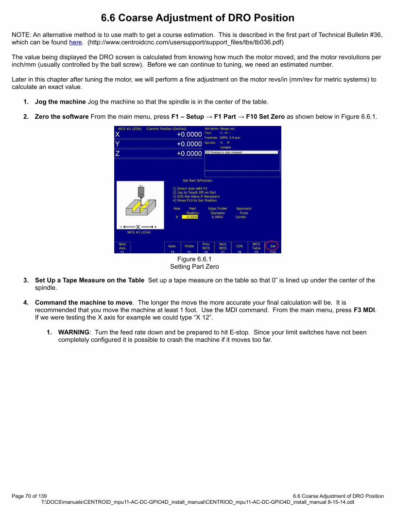
6.6 Coarse Adjustment of DRO Position
NOTE: An alternative method is to use math to get a course estimation. This is described in the first part of Technical Bulletin #36,which can be found here. (http://www.centroidcnc.com/usersupport/support_files/tbs/tb036.pdf)
The value being displayed the DRO screen is calculated from knowing how much the motor moved, and the motor revolutions per inch/mm (usually controlled by the ball screw). Before we can continue to tuning, we need an estimated number.
Later in this chapter after tuning the motor, we will perform a fine adjustment on the motor revs/in (mm/rev for metric systems) to calculate an exact value.
1. Jog the machine Jog the machine so that the spindle is in the center of the table.
2. Zero the software From the main menu, press F1 – Setup → F1 Part → F10 Set Zero as shown below in Figure 6.6.1.
3. Set Up a Tape Measure on the Table Set up a tape measure on the table so that 0” is lined up under the center of the spindle.
4. Command the machine to move. The longer the move the more accurate your final calculation will be. It is recommended that you move the machine at least 1 foot. Use the MDI command. From the main menu, press F3 MDI. If we were testing the X axis for example we could type “X 12”.
1. WARNING: Turn the feed rate down and be prepared to hit E-stop. Since your limit switches have not been completely configured it is possible to crash the machine if it moves too far.
Page 70 of 139 6.6 Coarse Adjustment of DRO PositionT:\DOCS\manuals\CENTROID_mpu11-AC-DC-GPIO4D_install_manual\CENTRIOD_mpu11-AC-DC-GPIO4D_install_manual 8-15-14.odt
Figure 6.6.1Setting Part Zero

5. Calculate the value Enter into the motor parameters menu. From the main menu press F1 -Setup → F3 Config. The password is 137, Press enter. Press F2 Mach → F2 Motor.
1. Imperial Units To calculate the value to be entered in the revs/inch field. Divide the distance moved (DRO value) by the distance that the axis actually moved (measuring tape). Multiply this result by the current value in the rev/inch fieldas circled in Figure 6.6.2.. This the new value that you will enter in the revs/inch field. If the axis traveled 6”, but the command was 7.5” 7.5/6 = 1.25, if the current revs/inch is 5.000 * 1.25 = 6.25 is the new value to enter in the revs/inch field.
2. Metric Units To calculate the value to be entered in the mm's/revs field. Divide the distance that the axis actually moved (measuring tape) by the distance commanded (DRO value). Multiply this result by the current value in the mm's/rev field as circled in Figure 6.6.2. This the new value that you will enter in the mm's/rev field. If the axis traveled 150mm”, but the command was 175mm, 150/175 = .85714, if the current mm's/rev is 5.08 * .85714 = 4.35428 is the new value to enter in the mm's/rev field.
6. Repeat the test as needed until the DRO matches the measuring tape.
7. Repeat the test for each axis.
Page 71 of 139 6.6 Coarse Adjustment of DRO PositionT:\DOCS\manuals\CENTROID_mpu11-AC-DC-GPIO4D_install_manual\CENTRIOD_mpu11-AC-DC-GPIO4D_install_manual 8-15-14.odt
Figure 6.6.2Adjusting motor revs/in or mm/rev

6.7 Homing the Machine
This same procedure is outline in Technical Bulletin #22, the latest version can be found here. (http://www.centroidcnc.com/usersupport/support_files/tbs/tb022.pdf)
1. Creating and Editing the Homing File
Your software comes with a default homing file that will work for most cases. If you have a machine with an unusual number of axes (such as a rotary table, CNC controlled grinder, CNC controlled drill press, extra lathe axes, etc..)or an unconventional limit switch configuration editing the home file will be necessary.
1. Exit CNC11.
2. Right click on your CNC11 desktop shortcut.
3. Select properties as shown in Figure 6.7.1.
4. In the shortcut tab, click on “Open File Location” as shown in Figure 6.7.2.
5. Windows explorer will open up in a new window showing the contents of your CNC11 directory (The directory will be called “CNCM” or “CNCT” depending on weather you have a mill or a lathe).
6. If “cncm.hom” (“cnct.hom” for lathes) is present, double click on it. If not the file present, it will have to be created. To create this file,.right click on cncm folder in the Windows File Explorer. (cnct for lathes). Select “new”, then select “text document”. A file will be created named “New Text Document.txt”. Rename this file “cncm.hom” (“cnct.hom”for lathes).
1. TIP Centroid recommends using Notepad++ as your default text editor. Notepad++ can be downloaded here. (http://notepad-plus-plus.org/)
7. Edit the file as needed as seen in Figure 6.7.3. There should be the correct number of axes defined in this file, and they should be listed in the correct order.
1. Centroid recommends that the Z positive axis is always homed first to prevent damage to the machine!
8. Make sure to save any changes that you make.
Page 72 of 139 6.7 Homing the MachineT:\DOCS\manuals\CENTROID_mpu11-AC-DC-GPIO4D_install_manual\CENTRIOD_mpu11-AC-DC-GPIO4D_install_manual 8-15-14.odt
Figure 6.7.1Steps 2 and 3
Figure 6.7.2Step 4
Figure 6.7.3Steps 5, 6, and 7

2. Start CNC11
3. Configure Limit Switches
1. NOTE: More information on Limit switches can be found in Technical Bulletin #127, which can be found here. (http://www.centroidcnc.com/usersupport/support_files/tbs/tb127.pdf)
2. Prerequisite: The motor movement direction mentioned must be configured correctly before testing the limit switches!
3. Enter the motor parameters menu. From the main menu press F1 -Setup → F3 Config. The password is 137, Press enter. Press F2 Mach → F2 Motor.
4. Move the machine so that the spindle is in the center of the table.
5. Manually trip the minus limit switch for the X axis. Try to jog the machine. It should only move in the plus direction. If it does not, change the limit switch in software as shown below in Figure 6.7.4.
4. Change the home type From the main screen press press F1-Setup → F3 -Config. The password is 137. Then press F3 Parms. Using the keyboard spacebar change “Machine home at power up” to “Limit Switch”.
5. Restart the Machine
6. Home the Machine: From the main menu press “start” on the jog panel or “Alt+S” to home the machine. The machine should move slowly towards each jog switch.
1. DANGER: Adjust the feedrate as needed so that the machine moves slowly. Be prepared to press E-stop if anything unexpected occurs.
2. NOTE: If the machine stops homing and the main menu says “Warning: Machine not homed” a limit switch was pressed in the wrong order and the machine faulted out. Please check the order of your limit switches as shown above.
Page 73 of 139 6.7 Homing the MachineT:\DOCS\manuals\CENTROID_mpu11-AC-DC-GPIO4D_install_manual\CENTRIOD_mpu11-AC-DC-GPIO4D_install_manual 8-15-14.odt
Figure 6.7.4Reversing limit switches in software
Figure 6.7.5Enabling homing off limit switches

6.8 Calculating Maximum Feed Rate
In past Centroid products the maximum feed rate and acceleration was determined by autotune. At the time of this writing, the AC/DC does not support auto tune. Maximum feed rate will have to be found manually.
Use the following equation to get a estimation: (maximum motor rpm / motor revolutions per inch) * 0.85 = maximum feed rate.
Enter the maximum feed rate in the Jog Parameters menu (F1 - Setup, F3 - Config, F2 – Mach., and then F1-Jog.).
The calculated maximum feedrate may be too high due to variations in supply voltage and load. Use MDI commands to test the calculated machine maximum feed rate. Gradually issue faster feed commands until the maximum is determined. If the machine is displaying the following symptoms the maximum feed rate is too fast and should be decreased:
• The load bar graph in the DRO display of the main menu is red, indicating excessive load on the motors• The software is giving errors such as position errors.• Motors are overheating.
Page 74 of 139 6.8 Calculating Maximum Feed RateT:\DOCS\manuals\CENTROID_mpu11-AC-DC-GPIO4D_install_manual\CENTRIOD_mpu11-AC-DC-GPIO4D_install_manual 8-15-14.odt
Figure 6.8.1Adjusting maximum feed rate

6.9 Tuning Your AC/DC
6.9.1 A Basic Introduction to Tuning and PID
AC/DC uses a PID loop to control motor movement. PID stands for Proportional, Integral, and Derivative. A PID controller calculates an error value as the difference between a measured process variable (motor position) and a desired set point (expected motor position). The controller attempts to minimize the error by adjusting the power to the motor. The PID controller’s calculation algorithm involves three separate parameters: the proportional, the integral and derivative values, denoted in the software as Kp, Ki, and Kd. Additionally, the motors inertia constant plays a large role in how the PID loop behaves.
The general idea of the tuning process is to minimize the Absolute Error (ErrAbs), which is measured in encoder counts. The inertia of the system varies from machine to machine, and the ideal PID values vary from motor to motor. To achieve optimal performance out of your motor, the inertia, position Kp, and position Kd values will have to be manually adjusted. Under most circumstances, the position Ki values do not need any adjustment. The current feedback Kp, Ki, and Kd (different from the position feedback Kp, Ki and Kd) should be left alone unless otherwise instructed.
Altering the PID values incorrectly could cause DRAMATIC changes in the way the servo system operates, leading to possible machine damage. Be cautious when adjusting the PID values, and be prepared to hit the E-stop as the motor may become unstable or move unpredictably if adjusted incorrectly.
Finally, PID tuning is not a black and white process. What is “good enough” of a value will depend on your accuracy needs and the capabilities of your system. Some experimentation is always required to find the ideal settings.
Centroid recommends using 40,000 counts per revolution encoders. Having lower resolution encoders is allowed, but might make the machine more difficult to tune.
Page 75 of 139 6.9.1 A Basic Introduction to Tuning and PIDT:\DOCS\manuals\CENTROID_mpu11-AC-DC-GPIO4D_install_manual\CENTRIOD_mpu11-AC-DC-GPIO4D_install_manual 8-15-14.odt
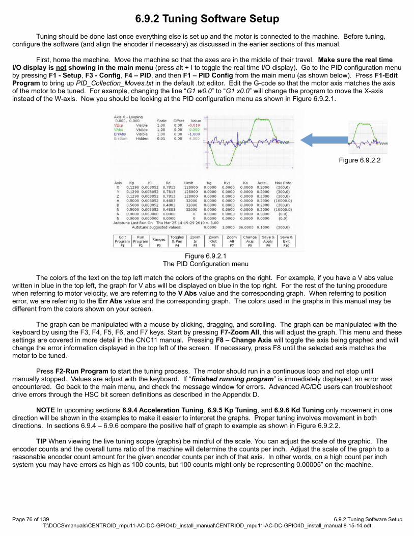
6.9.2 Tuning Software Setup
Tuning should be done last once everything else is set up and the motor is connected to the machine. Before tuning, configure the software (and align the encoder if necessary) as discussed in the earlier sections of this manual.
First, home the machine. Move the machine so that the axes are in the middle of their travel. Make sure the real time I/O display is not showing in the main menu (press alt + I to toggle the real time I/O display). Go to the PID configuration menuby pressing F1 - Setup, F3 - Config, F4 – PID, and then F1 – PID Config from the main menu (as shown below). Press F1-Edit Program to bring up PID_Collection_Moves.txt in the default .txt editor. Edit the G-code so that the motor axis matches the axis of the motor to be tuned. For example, changing the line “G1 w0.0” to “G1 x0.0” will change the program to move the X-axis instead of the W-axis. Now you should be looking at the PID configuration menu as shown in Figure 6.9.2.1.
The colors of the text on the top left match the colors of the graphs on the right. For example, if you have a V abs value written in blue in the top left, the graph for V abs will be displayed on blue in the top right. For the rest of the tuning procedure when referring to motor velocity, we are referring to the V Abs value and the corresponding graph. When referring to position error, we are referring to the Err Abs value and the corresponding graph. The colors used in the graphs in this manual may be different from the colors shown on your screen.
The graph can be manipulated with a mouse by clicking, dragging, and scrolling. The graph can be manipulated with the keyboard by using the F3, F4, F5, F6, and F7 keys. Start by pressing F7-Zoom All, this will adjust the graph. This menu and thesesettings are covered in more detail in the CNC11 manual. Pressing F8 – Change Axis will toggle the axis being graphed and will change the error information displayed in the top left of the screen. If necessary, press F8 until the selected axis matches the motor to be tuned.
Press F2-Run Program to start the tuning process. The motor should run in a continuous loop and not stop until manually stopped. Values are adjust with the keyboard. If “finished running program” is immediately displayed, an error was encountered. Go back to the main menu, and check the message window for errors. Advanced AC/DC users can troubleshoot drive errors through the HSC bit screen definitions as described in the Appendix D.
NOTE In upcoming sections 6.9.4 Acceleration Tuning, 6.9.5 Kp Tuning, and 6.9.6 Kd Tuning only movement in one direction will be shown in the examples to make it easier to interpret the graphs. Proper tuning involves movement in both directions. In sections 6.9.4 – 6.9.6 compare the positive half of graph to example as shown in Figure 6.9.2.2.
TIP When viewing the live tuning scope (graphs) be mindful of the scale. You can adjust the scale of the graphic. The encoder counts and the overall turns ratio of the machine will determine the counts per inch. Adjust the scale of the graph to a reasonable encoder count amount for the given encoder counts per inch of that axis. In other words, on a high count per inch system you may have errors as high as 100 counts, but 100 counts might only be representing 0.00005” on the machine.
Page 76 of 139 6.9.2 Tuning Software SetupT:\DOCS\manuals\CENTROID_mpu11-AC-DC-GPIO4D_install_manual\CENTRIOD_mpu11-AC-DC-GPIO4D_install_manual 8-15-14.odt
Figure 6.9.2.1The PID Configuration menu
Figure 6.9.2.2

6.9.3 Acceleration Tuning
Accel is the time for the axis to reach maximum velocity. An accel rate of 0.1 second is very fast, where an accel rate of 1.0 will be considered very slow.
Record the acceleration rate suggested by the software when the maximum feed rate was saved in the jog parameters menu (In Section 5.6). Entered this acceleration rate into the position PID menu (Press F1 - Setup, F3 - Config, F4 – PID, and then F1 – PID Config.) The rate provided is not the ideal acceleration rate, but a baseline number.
Press F1-Edit Program; adjust PID_Collection_Moves.txt so that it runs at the maximum feed rate as calculated in section 5.8 Save changes. Press F2-Run Program. Slowly decrease the acceleration time in 0.05 increments, testing the value in-between each change (Circled in 6.9.3.1). If you see any of the following symptoms the acceleration rate is too fast and needs to be slowed down:
The acceleration rate is causing shock or vibration as the machine moves. The machine movement becomes bumpy, rough, or jerky. The machine creates unusual or loud noises such as thunks or rapping noises. The software is giving errors such as position errors.
Page 77 of 139 6.9.3 Acceleration TuningT:\DOCS\manuals\CENTROID_mpu11-AC-DC-GPIO4D_install_manual\CENTRIOD_mpu11-AC-DC-GPIO4D_install_manual 8-15-14.odt
Figure 6.9.3.1Acceleration tuning
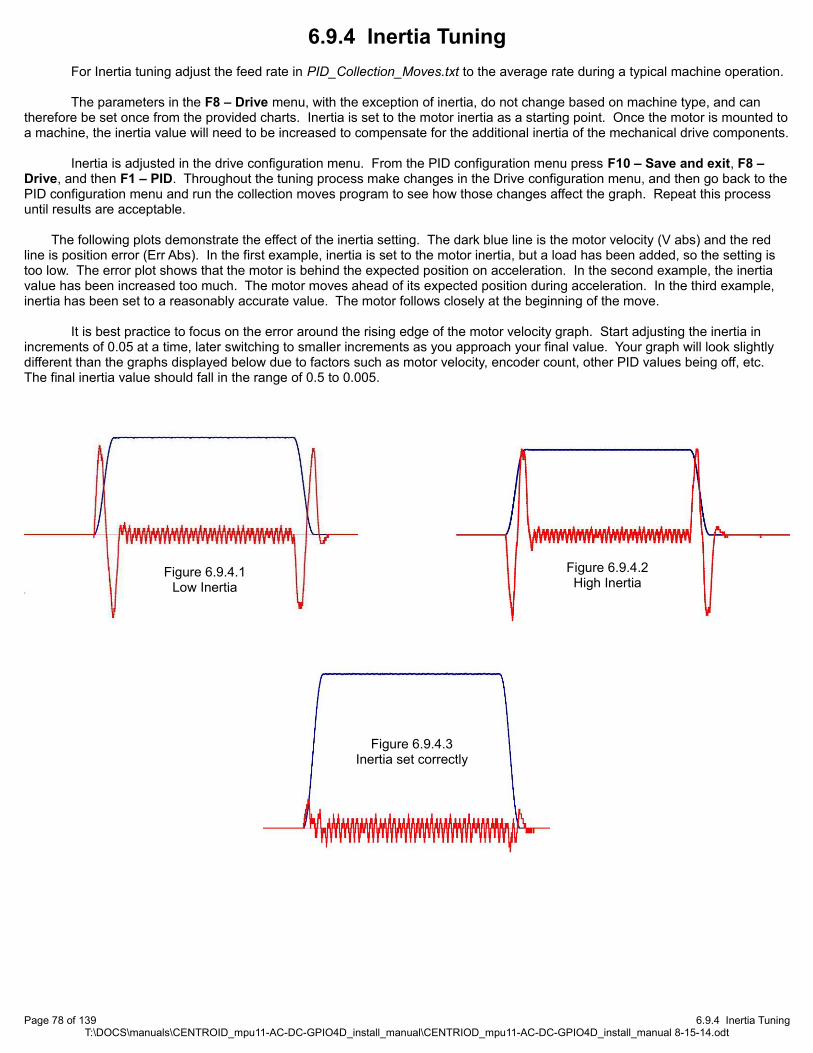
6.9.4 Inertia Tuning
For Inertia tuning adjust the feed rate in PID_Collection_Moves.txt to the average rate during a typical machine operation.
The parameters in the F8 – Drive menu, with the exception of inertia, do not change based on machine type, and can therefore be set once from the provided charts. Inertia is set to the motor inertia as a starting point. Once the motor is mounted toa machine, the inertia value will need to be increased to compensate for the additional inertia of the mechanical drive components.
Inertia is adjusted in the drive configuration menu. From the PID configuration menu press F10 – Save and exit, F8 – Drive, and then F1 – PID. Throughout the tuning process make changes in the Drive configuration menu, and then go back to thePID configuration menu and run the collection moves program to see how those changes affect the graph. Repeat this process until results are acceptable.
The following plots demonstrate the effect of the inertia setting. The dark blue line is the motor velocity (V abs) and the red line is position error (Err Abs). In the first example, inertia is set to the motor inertia, but a load has been added, so the setting is too low. The error plot shows that the motor is behind the expected position on acceleration. In the second example, the inertia value has been increased too much. The motor moves ahead of its expected position during acceleration. In the third example, inertia has been set to a reasonably accurate value. The motor follows closely at the beginning of the move.
It is best practice to focus on the error around the rising edge of the motor velocity graph. Start adjusting the inertia in increments of 0.05 at a time, later switching to smaller increments as you approach your final value. Your graph will look slightly different than the graphs displayed below due to factors such as motor velocity, encoder count, other PID values being off, etc. The final inertia value should fall in the range of 0.5 to 0.005.
Page 78 of 139 6.9.4 Inertia TuningT:\DOCS\manuals\CENTROID_mpu11-AC-DC-GPIO4D_install_manual\CENTRIOD_mpu11-AC-DC-GPIO4D_install_manual 8-15-14.odt
Figure 6.9.4.1Low Inertia
Figure 6.9.4.2High Inertia
Figure 6.9.4.3Inertia set correctly
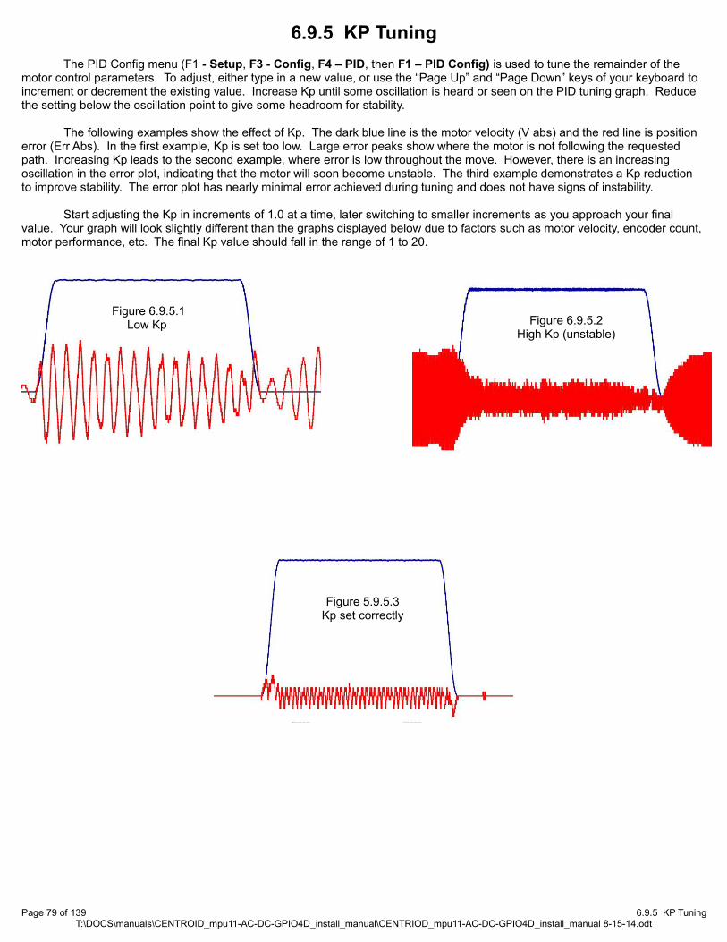
6.9.5 KP Tuning
The PID Config menu (F1 - Setup, F3 - Config, F4 – PID, then F1 – PID Config) is used to tune the remainder of the motor control parameters. To adjust, either type in a new value, or use the “Page Up” and “Page Down” keys of your keyboard to increment or decrement the existing value. Increase Kp until some oscillation is heard or seen on the PID tuning graph. Reduce the setting below the oscillation point to give some headroom for stability.
The following examples show the effect of Kp. The dark blue line is the motor velocity (V abs) and the red line is position error (Err Abs). In the first example, Kp is set too low. Large error peaks show where the motor is not following the requested path. Increasing Kp leads to the second example, where error is low throughout the move. However, there is an increasing oscillation in the error plot, indicating that the motor will soon become unstable. The third example demonstrates a Kp reduction to improve stability. The error plot has nearly minimal error achieved during tuning and does not have signs of instability.
Start adjusting the Kp in increments of 1.0 at a time, later switching to smaller increments as you approach your final value. Your graph will look slightly different than the graphs displayed below due to factors such as motor velocity, encoder count, motor performance, etc. The final Kp value should fall in the range of 1 to 20.
Page 79 of 139 6.9.5 KP TuningT:\DOCS\manuals\CENTROID_mpu11-AC-DC-GPIO4D_install_manual\CENTRIOD_mpu11-AC-DC-GPIO4D_install_manual 8-15-14.odt
Figure 6.9.5.1Low Kp Figure 6.9.5.2
High Kp (unstable)
Figure 5.9.5.3Kp set correctly

6.9.6 KD Tuning
After Kp has been adjusted, continue to tuning Kd. The Kd term adds stability to the effects of Kp. If Kp or Kd have been adjusted far from the default values, a second iteration of the tuning procedure is recommended. Because the two terms are dependent on each other, a better Kd setting may allow Kp to be adjusted for higher performance.
Incorrect Kd settings create oscillations. A low Kd setting creates low frequency oscillations. As Kd is increased, a high frequency oscillation will become noticeable. Often the high frequency oscillation will be audible before it is noticeable on the errorplot. The example shows an extreme case of oscillation due to Kd set too high. When Kd is set properly, it will dampen the Kp contribution, giving a smooth error plot.
Start adjusting the Kd in increments of 1.0 at a time, later switching to smaller increments as you approach your final value. Your graph will look slightly different than the graphs displayed below due to factors such as motor velocity, encoder count, motor performance, etc. The final Kd value should fall in the range of 1 to 20.
Page 80 of 139 6.9.6 KD TuningT:\DOCS\manuals\CENTROID_mpu11-AC-DC-GPIO4D_install_manual\CENTRIOD_mpu11-AC-DC-GPIO4D_install_manual 8-15-14.odt
Figure 6.9.6.1Low Kd
Figure 6.9.6.2High Kd
(unstable)
Figure 6.9.6.3Kd set correctly

6.10 Fine Adjust of DRO Position
This method is also described in Method 2 of Technical Bulletin #36, the latest version can be found here. (http://www.centroidcnc.com/usersupport/support_files/tbs/tb036.pdf)
For imperial machine configurations the number of motor revolutions required to move 1” must be calculated.
For metric machine configurations the number of mm's travelled during one revolution of the motor must be calculated.
3. Attach a dial indicator: Attach a dial test indicator (also known as a lever arm test indicator or a finger indicator) to the spindle.
1. NOTE: If you purchased a probe from Centroid, there is an easier method of doing this. Use of the probe will not be covered in this document.
4. Create a Test Fixture: Create an “L” shaped block of material to act as a reference for measurement as seen in Figure 6.10.1. The material should be appropriately 6 inches to 12 inches in length. A longer material will give you better accuracy. The exact length of the “long” part of the “L” needs to be known. A gauge block attached to another gauge block is recommended. An example test fixture is shown below.
5. Secure the test fixture Attach the test fixture to your machine so that it runs parallel to the axis being tested.
6. Move the dial indicator into position: Start from away from the block and jog towards the top of the “L”. Set jog panel mode to incremental when you get close. Move the spindle so that the dial indicator is reading as close to “0” as possible as demonstrated in Figure 6.10.2.
1. NOTE: Only jog towards the block. If you jog too close and have to back up slightly, backlash will be introduced into your measurement. In that case you will have to back way up and start again.
Page 81 of 139 6.10 Fine Adjust of DRO PositionT:\DOCS\manuals\CENTROID_mpu11-AC-DC-GPIO4D_install_manual\CENTRIOD_mpu11-AC-DC-GPIO4D_install_manual 8-15-14.odt
The long part of the “L” is from is guage block measuring 12.000”
Figure 6.10.1Example test fixture
Figure 6.10.2Zeroing the dial indicator

7. Zero the software From the main menu, press F1 – Setup → F1 Part → F10 Set Zero as shown below in Figure 6.10.3.
8. Raise the spindle: Move the spindle so that it is away from the text fixture. If we are configuring the X or Y axes we need to the raise the Z-axis.
9. Move to the base of the “L”: Jog towards the base of the “L”. Set jog panel mode to incremental when you get close. Move the spindle so that the dial indicator is reading as close to “0” as possible as shown in Figure 6.10.4.
1. NOTE: Only jog towards the block. If you jog too close and have to back up slightly, backlash will be introduced into your measurement. In that case you will have to start the test again.
Page 82 of 139 6.10 Fine Adjust of DRO PositionT:\DOCS\manuals\CENTROID_mpu11-AC-DC-GPIO4D_install_manual\CENTRIOD_mpu11-AC-DC-GPIO4D_install_manual 8-15-14.odt
Figure 6.10.3Setting part zero
Figure 6.10.4Zeroing the dial indicator again

10. Calculate Values: Go into the motor parameters menu. From the main menu press F1 -Setup → F3 Config. The password is 137, Press enter. Press F2 Mach → F2 Motor.
1. Imperial Units: To calculate the value to be entered in the revs/inch field. Divide the distance moved (DRO value) by the distance that the axis actually moved. Multiply this result by the current value in the rev/inch field. This the new value that you will enter in the revs/inch field. If the axis traveled 6”, but the command was 7.5” 7.5/6= 1.25, if the current revs/inch is 5.000 * 1.25 = 6.25 is the new value to enter in the revs/inch field.
2. Metric Units: To calculate the value to be entered in the mm's/revs field. Divide the distance that the axis actuallymoved by the distance commanded (DRO value). Multiply this result by the current value in the mm's/rev field. This the new value that you will enter in the mm's/rev field. If the axis traveled 150mm”, but the command was 175mm, 150/175 = .85714285, if the current mm's/rev is 5.08 * 0.85714 = 4.35428 is the new value to enter in the mm's/rev field.
11. Repeat the test as needed until the DRO measures the same as the gauge block.
12. Repeat the test for each axis.
Page 83 of 139 6.10 Fine Adjust of DRO PositionT:\DOCS\manuals\CENTROID_mpu11-AC-DC-GPIO4D_install_manual\CENTRIOD_mpu11-AC-DC-GPIO4D_install_manual 8-15-14.odt
Figure 6.10.5Fine adjustment of motor res/in or mm/rev
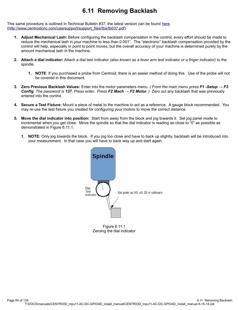
6.11 Removing Backlash
This same procedure is outlined in Technical Bulletin #37, the latest version can be found here.(http://www.centroidcnc.com/usersupport/support_files/tbs/tb037.pdf)
1. Adjust Mechanical Lash: Before configuring the backlash compensation in the control, every effort should be made to reduce the mechanical lash in your machine to less than 0.001”. The “electronic” backlash compensation provided by the control will help, especially in point to point moves, but the overall accuracy of your machine is determined purely by the amount mechanical lash in the machine.
2. Attach a dial indicator: Attach a dial test indicator (also known as a lever arm test indicator or a finger indicator) to the spindle.
1. NOTE: If you purchased a probe from Centroid, there is an easier method of doing this. Use of the probe will not be covered in this document.
3. Zero Previous Backlash Values: Enter into the motor parameters menu. ( From the main menu press F1 -Setup → F3 Config. The password is 137, Press enter. Press F2 Mach → F2 Motor. ) Zero out any backlash that was previously entered into the control.
4. Secure a Test Fixture: Mount a piece of metal to the machine to act as a reference. A gauge block recommended. You may re-use the test fixture you created for configuring your motors to move the correct distance.
5. Move the dial indicator into position: Start from away from the block and jog towards it. Set jog panel mode to incremental when you get close. Move the spindle so that the dial indicator is reading as close to “0” as possible as demonstrated in Figure 6.11.1.
1. NOTE: Only jog towards the block. If you jog too close and have to back up slightly, backlash will be introduced into your measurement. In that case you will have to back way up and start again.
Page 84 of 139 6.11 Removing BacklashT:\DOCS\manuals\CENTROID_mpu11-AC-DC-GPIO4D_install_manual\CENTRIOD_mpu11-AC-DC-GPIO4D_install_manual 8-15-14.odt
Figure 6.11.1Zeroing the dial indicator
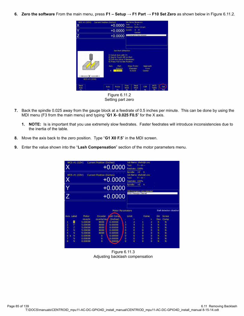
6. Zero the software From the main menu, press F1 – Setup → F1 Part → F10 Set Zero as shown below in Figure 6.11.2.
7. Back the spindle 0.025 away from the gauge block at a feedrate of 0.5 inches per minute. This can be done by using the MDI menu (F3 from the main menu) and typing “G1 X- 0.025 F0.5” for the X axis.
1. NOTE: Is is important that you use extremely slow feedrates. Faster feedrates will introduce inconsistencies due to the inertia of the table.
8. Move the axis back to the zero position. Type “G1 X0 F.5” in the MDI screen.
9. Enter the value shown into the “Lash Compensation” section of the motor parameters menu.
Page 85 of 139 6.11 Removing BacklashT:\DOCS\manuals\CENTROID_mpu11-AC-DC-GPIO4D_install_manual\CENTRIOD_mpu11-AC-DC-GPIO4D_install_manual 8-15-14.odt
Figure 6.11.2Setting part zero
Figure 6.11.3Adjusting backlash compensation

6.12 Deadstart
Deadstart is located in the jog parameters menu and has to do with direction reversal of an axis. The deadstart usually doesn't have to be changed from the default value on a Milling machine. Sometimes very light wood routing tables with very low friction and low inertia can benefit from a deadstart change along with other "hand tuning." Call in if you have this case.
6.13 Other Misc Tuning InformationKg, Kv, and Ka in the PID position menu are not used and do not need adjusted. Ki does not need to be adjusted under
most circumstances. After tuning the other values of the PID loop, experimentation with Ki values may sometimes help to reduce error. Adjust Ki in increments of 0.005, with the final value falling in the range of 0.001 to 0.25.
6.14 Performing a System Test
In some versions of CNC11 software, when finished, the main menu will display a message saying “Machine Setup Not Completed. Machine Is Not Ready To Run. Contact Your Dealer” as shown below.
At this point you will need to run the System Test to clear this message. Documentation on how to perform a system test is located here. (http://www.ajaxcnc.com/tech/downloads/manuals/install/Systemtest.pdf)
If the instructions outlined in system test do not apply to your system, contact technical support.
Page 86 of 139 6.12 DeadstartT:\DOCS\manuals\CENTROID_mpu11-AC-DC-GPIO4D_install_manual\CENTRIOD_mpu11-AC-DC-GPIO4D_install_manual 8-15-14.odt
Figure 6.14.1Machine Requiring a System Test
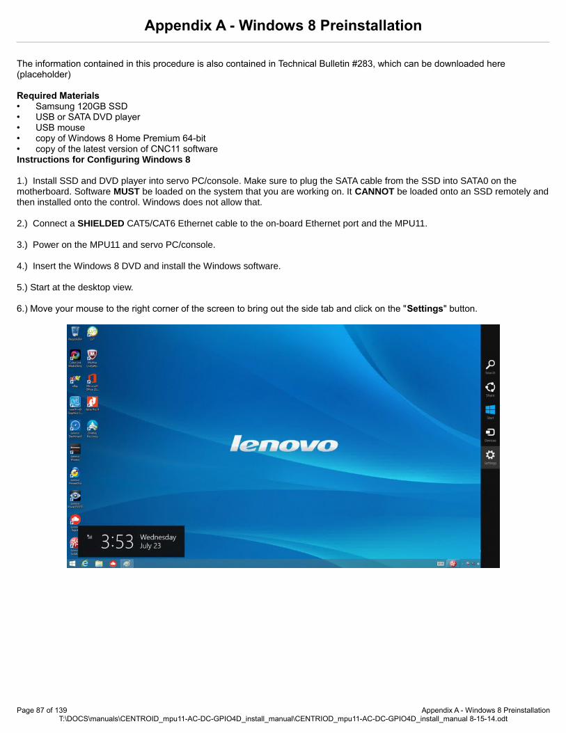
Appendix A - Windows 8 Preinstallation
The information contained in this procedure is also contained in Technical Bulletin #283, which can be downloaded here (placeholder)
Required Materials• Samsung 120GB SSD• USB or SATA DVD player• USB mouse• copy of Windows 8 Home Premium 64-bit• copy of the latest version of CNC11 softwareInstructions for Configuring Windows 8
1.) Install SSD and DVD player into servo PC/console. Make sure to plug the SATA cable from the SSD into SATA0 on the motherboard. Software MUST be loaded on the system that you are working on. It CANNOT be loaded onto an SSD remotely andthen installed onto the control. Windows does not allow that.
2.) Connect a SHIELDED CAT5/CAT6 Ethernet cable to the on-board Ethernet port and the MPU11.
3.) Power on the MPU11 and servo PC/console.
4.) Insert the Windows 8 DVD and install the Windows software. 5.) Start at the desktop view.
6.) Move your mouse to the right corner of the screen to bring out the side tab and click on the "Settings" button.
Page 87 of 139 Appendix A - Windows 8 PreinstallationT:\DOCS\manuals\CENTROID_mpu11-AC-DC-GPIO4D_install_manual\CENTRIOD_mpu11-AC-DC-GPIO4D_install_manual 8-15-14.odt

7.) Next click on the "Control Panel"
8.) Go to "Uninstall a Program" directly underneath "Programs”.
9.) Next uninstall any un-necessary programs that might have come from your computer manufacture. Some of these may includeMcCaffey Antivirus, various trial offers, etc.
Page 88 of 139 Appendix A - Windows 8 PreinstallationT:\DOCS\manuals\CENTROID_mpu11-AC-DC-GPIO4D_install_manual\CENTRIOD_mpu11-AC-DC-GPIO4D_install_manual 8-15-14.odt
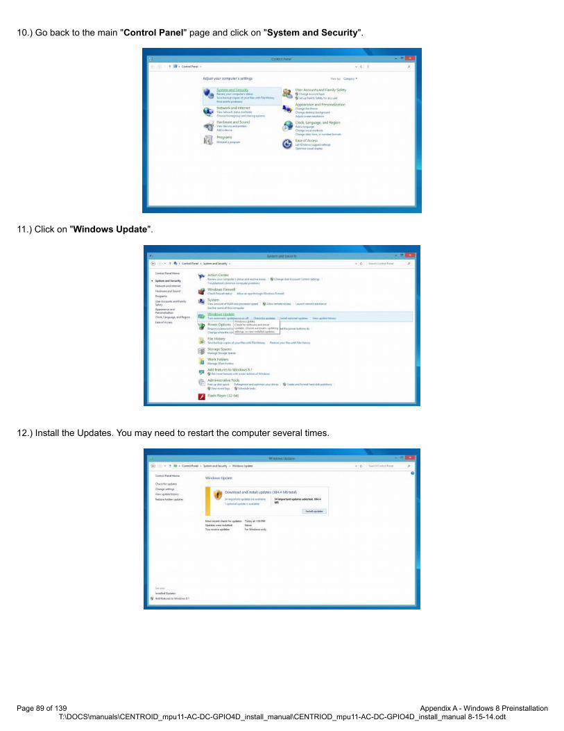
10.) Go back to the main "Control Panel" page and click on "System and Security".
11.) Click on "Windows Update".
12.) Install the Updates. You may need to restart the computer several times.
Page 89 of 139 Appendix A - Windows 8 PreinstallationT:\DOCS\manuals\CENTROID_mpu11-AC-DC-GPIO4D_install_manual\CENTRIOD_mpu11-AC-DC-GPIO4D_install_manual 8-15-14.odt

13.)Keep going until you see the below screen, stating that no more updates are available. Then click on the "Change settings" onthe left side.
14.) From the dropdown under "Important updates" select "Never check for updates" and click OK at the bottom after.
15.) Go back to the Control Panel view and click on "System and Security".
Page 90 of 139 Appendix A - Windows 8 PreinstallationT:\DOCS\manuals\CENTROID_mpu11-AC-DC-GPIO4D_install_manual\CENTRIOD_mpu11-AC-DC-GPIO4D_install_manual 8-15-14.odt

16.) Click on the "Action Center".
17.) Click on "Change User Account Control Settings" and then drag the bar to the "Never notify" at the bottom and click OK.
18.) Next click on "Change Action Center Settings".
Page 91 of 139 Appendix A - Windows 8 PreinstallationT:\DOCS\manuals\CENTROID_mpu11-AC-DC-GPIO4D_install_manual\CENTRIOD_mpu11-AC-DC-GPIO4D_install_manual 8-15-14.odt

19.) Un-select every checkbox and click OK.
20.) Go back to the main Control Panel page and click on "System and Security".
21.) Click on "Windows Firewall".
Page 92 of 139 Appendix A - Windows 8 PreinstallationT:\DOCS\manuals\CENTROID_mpu11-AC-DC-GPIO4D_install_manual\CENTRIOD_mpu11-AC-DC-GPIO4D_install_manual 8-15-14.odt

22.) Click on "Turn Windows Firewall on or off" on the left hand side.
23.) Click on the "Turn off Windows Firewall" buttons on both the Private and Public network settings. Click OK at the bottom.
24.) Go back to the Control Panel Main page and click on "System and Security".
Page 93 of 139 Appendix A - Windows 8 PreinstallationT:\DOCS\manuals\CENTROID_mpu11-AC-DC-GPIO4D_install_manual\CENTRIOD_mpu11-AC-DC-GPIO4D_install_manual 8-15-14.odt
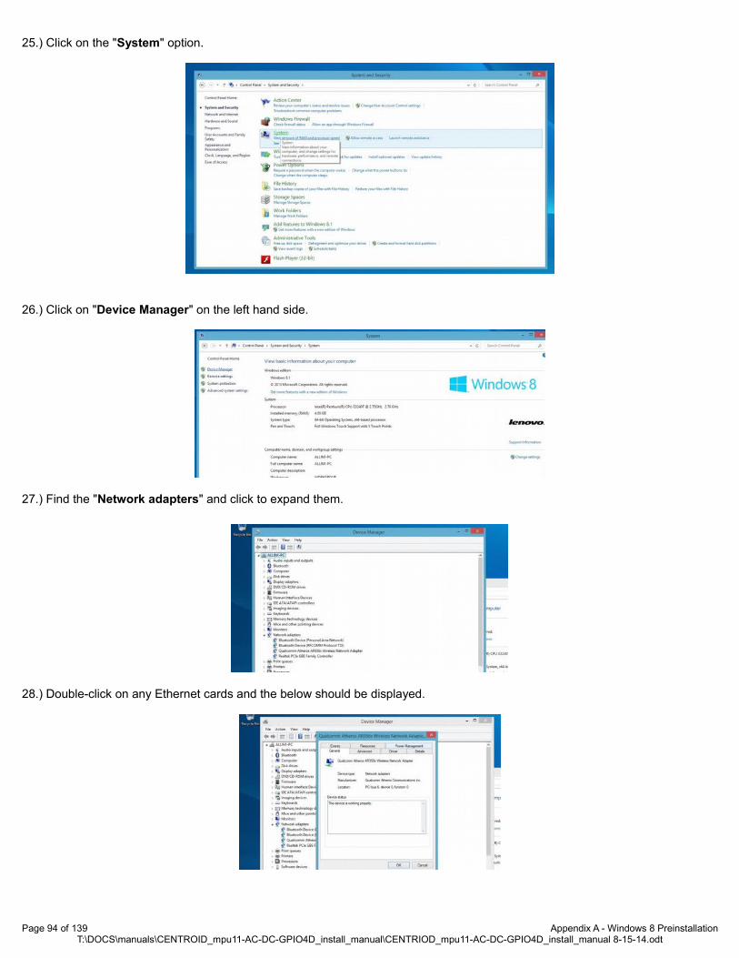
25.) Click on the "System" option.
26.) Click on "Device Manager" on the left hand side.
27.) Find the "Network adapters" and click to expand them.
28.) Double-click on any Ethernet cards and the below should be displayed.
Page 94 of 139 Appendix A - Windows 8 PreinstallationT:\DOCS\manuals\CENTROID_mpu11-AC-DC-GPIO4D_install_manual\CENTRIOD_mpu11-AC-DC-GPIO4D_install_manual 8-15-14.odt

29.)Click on the "Power Management" tab and the uncheck all the boxes. Click OK and do the same for any other Ethernet Cards available.
30.) Go back to the "System and Security" screen and click on "Power Options”.
31.) Click on the circle with and arrow to bring up the "additional plans" then select "High performance" and click "Change plansettings".
32.) Click on the "Change advanced power settings".
Page 95 of 139 Appendix A - Windows 8 PreinstallationT:\DOCS\manuals\CENTROID_mpu11-AC-DC-GPIO4D_install_manual\CENTRIOD_mpu11-AC-DC-GPIO4D_install_manual 8-15-14.odt

33.) Click on the "Change settings that are currently unavailable".
34.) Under "Hard disk" set "Turn off hard disk after" to "Never"
35.) Under the "USB settings" , for "USB selective suspend setting" select "Disabled"
36.) Under "Display" set "Turn off display after" to "Never". Then click "Apply". Than close the open window.
Page 96 of 139 Appendix A - Windows 8 PreinstallationT:\DOCS\manuals\CENTROID_mpu11-AC-DC-GPIO4D_install_manual\CENTRIOD_mpu11-AC-DC-GPIO4D_install_manual 8-15-14.odt

37.) Press "Ctrl" + "Alt" + "Delete" all at the same time. Select "Task Manager", then click on the more details button.
38.) Next click on the "Startup" tab and click on each Item and then click "Disable" at the bottom. Then close the window.
39.) Click on the "Date and Time" section of the taskbar on the lower right hand corner. Click “Change Date and Time Settings”.
40.) Select the "Internet Time" tab and click on "Change settings..."
Page 97 of 139 Appendix A - Windows 8 PreinstallationT:\DOCS\manuals\CENTROID_mpu11-AC-DC-GPIO4D_install_manual\CENTRIOD_mpu11-AC-DC-GPIO4D_install_manual 8-15-14.odt

41.) Uncheck the "Synchronize with an Internet time server" box and click OK.
TIP: If you want to eliminate the scan & fix pop up and autoplay pop up when you plug in your USB stick, you will need to do the following. To suppress the scan & fix click on the Windows icon and type: msconfig and click on the "Services Tab" then scroll down and uncheck "Shell Hardware Detection". Click "Apply" then "Ok" and then you will need to power cycle the PC.
TIP: To suppress the autoplay, click on Windows start icon and type: autoplay then uncheck "use AutoPlay for all media and devices" and click "Save".
You may now continue to Section 3.2, CNC11 and PLC Installation.
Page 98 of 139 Appendix A - Windows 8 PreinstallationT:\DOCS\manuals\CENTROID_mpu11-AC-DC-GPIO4D_install_manual\CENTRIOD_mpu11-AC-DC-GPIO4D_install_manual 8-15-14.odt

Appendix B - Windows 7 Preinstallation
This procedure is outlined in Technical Bulletin 244, the latest version can be found here.(http://www.centroidcnc.com/usersupport/support_files/tbs/tb244.pdf)
Required Materials
• OCZ Vertex Series 30Gb SATA II SSD• USB or SATA DVD player• USB mouse• copy of Windows 7 Home Premium 64-bit• copy of the latest version of CNC11 software
Instructions for Configuring Windows 7
1. Install SSD and DVD player into servo PC/console. Make sure to plug the SATA cable from the SSD into SATA0 on the motherboard. Software MUST be loaded on the system that you are working on. It CANNOT be loaded onto an SSD remotely and then installed onto the control. Windows does not allow that.
2. Connect a SHIELDED CAT5/CAT6 Ethernet cable to the on-board Ethernet port and the MPU11 as shown in Section 2.3.
3. Power on the MPU11 and servo PC/console.
4. Insert the Windows 7 DVD and install the Windows software.
5. Using the mouse, right click on the task bar, which is located on the bottom of the screen, and select “Properties” as shown below.
6. Check the “Auto Hide” option under the “taskbar” tab.
Page 99 of 139 Appendix B - Windows 7 PreinstallationT:\DOCS\manuals\CENTROID_mpu11-AC-DC-GPIO4D_install_manual\CENTRIOD_mpu11-AC-DC-GPIO4D_install_manual 8-15-14.odt

7. Right click on the “Action Center” icon, which is the green flag that is located on the right side on the task bar.
8. Select “Open Action Center”.
9. Click on “Change Settings”.
Page 100 of 139 Appendix B - Windows 7 PreinstallationT:\DOCS\manuals\CENTROID_mpu11-AC-DC-GPIO4D_install_manual\CENTRIOD_mpu11-AC-DC-GPIO4D_install_manual 8-15-14.odt

10. Make sure that all of the options have their respective boxes unchecked.
11. Click on the “Start” button and select “Control Panel”.
Page 101 of 139 Appendix B - Windows 7 PreinstallationT:\DOCS\manuals\CENTROID_mpu11-AC-DC-GPIO4D_install_manual\CENTRIOD_mpu11-AC-DC-GPIO4D_install_manual 8-15-14.odt

12. Select “User Accounts & Family Safety”.
13. Click on “User Accounts”
Page 102 of 139 Appendix B - Windows 7 PreinstallationT:\DOCS\manuals\CENTROID_mpu11-AC-DC-GPIO4D_install_manual\CENTRIOD_mpu11-AC-DC-GPIO4D_install_manual 8-15-14.odt
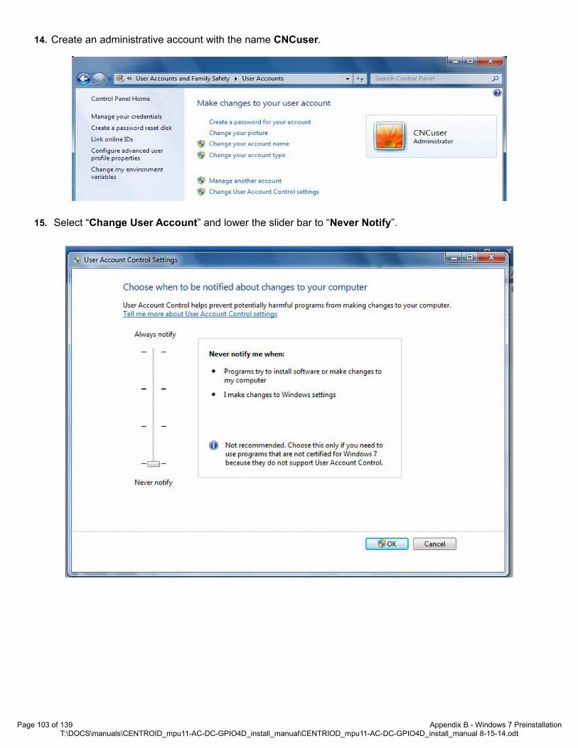
14. Create an administrative account with the name CNCuser.
15. Select “Change User Account” and lower the slider bar to “Never Notify”.
Page 103 of 139 Appendix B - Windows 7 PreinstallationT:\DOCS\manuals\CENTROID_mpu11-AC-DC-GPIO4D_install_manual\CENTRIOD_mpu11-AC-DC-GPIO4D_install_manual 8-15-14.odt

16. Go back to “Control Panel” and select “System & Security”.
17. Select “Windows Update”
Page 104 of 139 Appendix B - Windows 7 PreinstallationT:\DOCS\manuals\CENTROID_mpu11-AC-DC-GPIO4D_install_manual\CENTRIOD_mpu11-AC-DC-GPIO4D_install_manual 8-15-14.odt

18. Click on “Install Updates”.
19. The computer may need to be restarted after the updates are done installing. Go back to the above screen and keep clicking “Install Updates” until you see the screen below. Next click on “Change Settings” on the left hand tab.
Page 105 of 139 Appendix B - Windows 7 PreinstallationT:\DOCS\manuals\CENTROID_mpu11-AC-DC-GPIO4D_install_manual\CENTRIOD_mpu11-AC-DC-GPIO4D_install_manual 8-15-14.odt

20. Select “Important Updates” and then select “Never Check for Updates”.
21. Go back to “Control Panel”, "System and Securities".
22. Select “Power Options”.
23. Click on the down tab next to “Show additional plans”.
24. Next select “High performance” then select “Change Plan Settings”.
Page 106 of 139 Appendix B - Windows 7 PreinstallationT:\DOCS\manuals\CENTROID_mpu11-AC-DC-GPIO4D_install_manual\CENTRIOD_mpu11-AC-DC-GPIO4D_install_manual 8-15-14.odt

25. Then select “Change Advanced Power Settings”.
26. You should now be at the Power Options screen.
Page 107 of 139 Appendix B - Windows 7 PreinstallationT:\DOCS\manuals\CENTROID_mpu11-AC-DC-GPIO4D_install_manual\CENTRIOD_mpu11-AC-DC-GPIO4D_install_manual 8-15-14.odt

27. Make sure that the settings are as described below:
1. High Performance
1. Required password → NO
2. HDD
1. Turn off HDD → Never
3. Desktop Background Settings
1. Slide Show → Available
4. Wireless Adapter Setting
1. Power Saving mode → Maximum performance
5. Sleep
1. Sleep after → Never
2. Allow hybrid sleep → ON
3. Hibernate after → Never
4. Allow wake times → Enable
6. USB Settings
1. USB selective suspend → Disable
7. Power Buttons
1. Power button action → Shut down
2. Sleep button → Sleep
8. PCI Express
1. Link state power manage → OFF
9. Processor Power Management
1. Minimum processor state → 100%
2. System cooling policy → Active
3. Maximum processor state → 100%
10. Display
1. Turn off display after → Never
11. Multimedia Settings
1. When sharing media → Prevent idling to sleep
2. When playing video → Optimize video quality
Page 108 of 139 Appendix B - Windows 7 PreinstallationT:\DOCS\manuals\CENTROID_mpu11-AC-DC-GPIO4D_install_manual\CENTRIOD_mpu11-AC-DC-GPIO4D_install_manual 8-15-14.odt

28. Next the user password expiration needs turned off. Click the Windows icon, then type: cmd to bring up the command prompt.
29. Make sure the title bar reads "Administrator: C\Windows\system32\cmd.exe",
1. Then type: net accounts (press enter).
2. Third line down will read " Maximum password age (days): 42",
3. Confirm and then type: net accounts /maxpwage:unlimited (press enter).
30. Type: net accounts again to verify that it says "unlimited" beside the "Maximum password age".
1. If it does type: exit (press enter) to close the command prompt window.
Page 109 of 139 Appendix B - Windows 7 PreinstallationT:\DOCS\manuals\CENTROID_mpu11-AC-DC-GPIO4D_install_manual\CENTRIOD_mpu11-AC-DC-GPIO4D_install_manual 8-15-14.odt
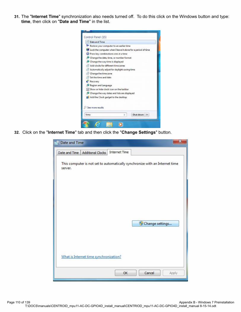
31. The "Internet Time" synchronization also needs turned off. To do this click on the Windows button and type: time, then click on "Date and Time" in the list.
32. Click on the "Internet Time" tab and then click the "Change Settings" button.
Page 110 of 139 Appendix B - Windows 7 PreinstallationT:\DOCS\manuals\CENTROID_mpu11-AC-DC-GPIO4D_install_manual\CENTRIOD_mpu11-AC-DC-GPIO4D_install_manual 8-15-14.odt

33. Uncheck the box for "Synchronize with an Internet time server", then click "OK" to close that window and click "OK" again to close the "Date and Time" window.
34. Click on the "Start Button" and type: “network connection” in the search window. Click on "View Network".
Page 111 of 139 Appendix B - Windows 7 PreinstallationT:\DOCS\manuals\CENTROID_mpu11-AC-DC-GPIO4D_install_manual\CENTRIOD_mpu11-AC-DC-GPIO4D_install_manual 8-15-14.odt

35. Right click on the network card. Click on "Properties".
36. Click "Configure". Click on the "Power Management" tab and make sure that the "Allow the computer to turn offthis device to save power" box is unchecked.
Page 112 of 139 Appendix B - Windows 7 PreinstallationT:\DOCS\manuals\CENTROID_mpu11-AC-DC-GPIO4D_install_manual\CENTRIOD_mpu11-AC-DC-GPIO4D_install_manual 8-15-14.odt

37. After Windows 7 is configured the last thing you will need to do is activate Windows7, which can be done via the Internet or phone.
38. Open "Windows Activation" by clicking the "Start" button, then right click "Computer", then click "Properties", and then click "Activate Windows now".
1. Note: If you are installing a new SSD in which Centroid has installed the Windows7 operating system, you willNEED to change the product key before attempting to activate Windows7 by clicking on the "Start" button, then click on "Control Panel", then click on "System & Security", then click on "System", scroll all the way to the bottom and click on "Change product key".
39. If using the Internet and Windows7 detects an Internet connection, click on "Activate Windows online now", type in the Windows7 product key when prompted, then click "Next" and follow the remaining instructions.
40. If activating Windows7 via the phone, click on "Show me other ways to activate", type in the Windows7 product key when prompted, then click "Next", then click "Use the automated phone system", then click on the location nearest you from the drop-down list, then click "Next". Call one of the phone numbers listed and an automated system will guide you through the activation process.
1. When prompted, enter the installation ID that's listed on the screen into the phone's keypad.
2. Type the confirmation ID that the phone system gives you into the space provided under Step 3, then click "Next", andthen follow the remaining instructions.
41. TIP: If you want to eliminate the scan & fix pop up and autoplay pop up when you plug in your USB stick, you will need to do the following. To suppress the scan & fix click on the Windows icon and type: msconfig and click on the "Services Tab" then scroll down and uncheck "Shell Hardware Detection". Click "Apply" then "Ok" and then you will need to powercycle the PC.
42. TIP: To suppress the autoplay, click on Windows start icon and type: autoplay then uncheck "use AutoPlay for all media and devices" and click "Save".
43. You may now continue to Section 3.2, CNC11 and PLC Installation.
Page 113 of 139 Appendix B - Windows 7 PreinstallationT:\DOCS\manuals\CENTROID_mpu11-AC-DC-GPIO4D_install_manual\CENTRIOD_mpu11-AC-DC-GPIO4D_install_manual 8-15-14.odt

APPENDIX C - GENERAL TROUBLESHOOTINGDiagnosing Errors and Common Problems
1. Does the MPU11 have power? Check that MPU11 power supply is receiving AC power (85-264VAC). Check that MPU11 is receiving 5VDC & +-12VDC. If the MPU11 power supply is receiving AC power but the MPU11 is not receiving any or all of 5 or +-12VDC signals, remove the power plug from the mpu11 and measure DC voltage between red & black = 5VDC, gray & orange = +12VDC, gray & purple = -12VDC. If any of these are missing, replace the power supply. If the signals all are present when the plug is disconnected, replace/repair the MPU11.
2. Are the MPU11 LED's in the correct states? Check that the LED's are initializing correctly. About 30 seconds after power is applied, the LED's states should be as shown below. If they are not, it indicates that the MPU11 hardware did not initialize correctly and that it needs to be replaced or repaired.
3. Is the network cable plugged in? Is the network cable plugged in to both the MPU11 and the PC? If so, is the green LED on where the network cable plugs into the MPU11 and also on the PC? If the LED's are off, try another shielded CAT5/CAT6 Ethernet cable. Note: A non-shielded cable can be used temporarily for testing purposes.
4. Can you ping the network adapter in the PC?Open a command prompt Go to Start->All Programs->Accessories-> Command Prompt and type ping 10.168.41.1 and press enter. If the network adapter is working and configured correctly, you should see the screen(s) below. If you confirmed the configuration of the network adapter (step 5)in the PC, powered everything off and back up and still get timeouts, there is a problem with the network adapter in your PC. If you see the screen below (no timeouts) you can skip to step 6.
Page 114 of 139 Appendix C - General TroubleshootingT:\DOCS\manuals\CENTROID_mpu11-AC-DC-GPIO4D_install_manual\CENTRIOD_mpu11-AC-DC-GPIO4D_install_manual 8-15-14.odt
Symptom or ErrorError Initializing MPU11
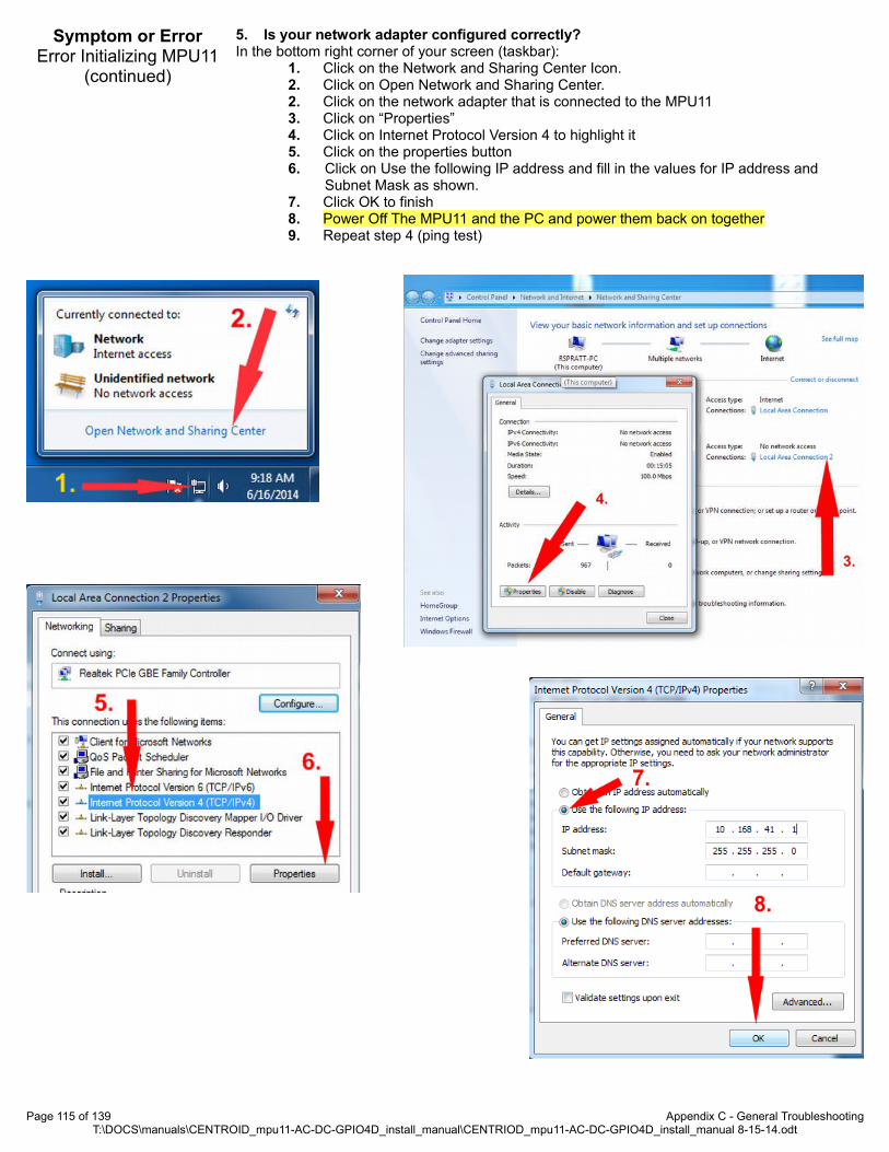
5. Is your network adapter configured correctly? In the bottom right corner of your screen (taskbar):
1. Click on the Network and Sharing Center Icon.2. Click on Open Network and Sharing Center. 2. Click on the network adapter that is connected to the MPU11 3. Click on “Properties”4. Click on Internet Protocol Version 4 to highlight it5. Click on the properties button6. Click on Use the following IP address and fill in the values for IP address and
Subnet Mask as shown.7. Click OK to finish8. Power Off The MPU11 and the PC and power them back on together9. Repeat step 4 (ping test)
Page 115 of 139 Appendix C - General TroubleshootingT:\DOCS\manuals\CENTROID_mpu11-AC-DC-GPIO4D_install_manual\CENTRIOD_mpu11-AC-DC-GPIO4D_install_manual 8-15-14.odt
Symptom or ErrorError Initializing MPU11
(continued)

6. Can you ping the MPU11? Open a command prompt. Go to Start->All Programs->Accessories->Command Prompt and typeping 10.168.41.2 and press enter. You should see the screen(s) below. If you get timeouts, there may be a problem with your firewall or anti-virus or it may be a problem with the MPU11 itself. Uninstall any anti-virus and disable all firewalls. And try to ping the MPU11 again. If you are sure there are no firewalls active and that all anti-virus has been uninstalled and you still can't ping the MPU11, the MPU11 may be defective. NOTE: It is rare that communication problems are caused by a defect in the mpu11.
7. Have you recently upgraded the CNC11 software from a very old version? (pre-v3.06) There is a firmware incompatibility between versions prior to 3.06 and versions 3.08 and later. To fix this, download v3.06 here: v3.06 Once downloaded, install version 3.06 -but do not install a PLC program. Run CNC11 v3.06 until it initializes and enters DEMO/Options screen. You can now exit and install version 3.08 or later without issue
8. Are you sure all anti-virus and firewalls have been uninstalled? If the MPU11 can be successfully pinged and does not have the compatibility issue between software versions prior to 3.06 and versions 3.08 or later, it is virtually unheard of for an MPU11 tobe the cause of “Error Initializing MPU11” messages. Windows firewall, other firewalls and anti-virus will absolutely cause this fault even when they have been configured to allow cncm to communicate. Make sure they are completely disabled/uninstalled.
1. Are you using a shielded CAT5 cable? This error is most often caused by noise. Make sure the cable connected between the MPU11 and the network adapter is shielded, a shielded CAT5 cable will have metal clips on each end. If it doesn't have metal clips on each end, it's not shielded.
2. Does the CAT5 cable run directly from the MPU11 to the PC? The cable running between the MPU11 and PC should be a single shielded cable that does not connect to any switches, hubs or butt connectors. Any of these things will effectively defeat the shielding and introduce noise. They will also likely introduce propagation delays which will cause this error as well.
3. Does the CAT5 cable run next to any 3 phase or power cables? The Cat5 cable should never be run alongside any 3 phase or power cables. Make sure the CAT5cable is run well away from Spindle and servo motors and any other cables with inductive loads such as coolant and lube pumps, solenoids.
4. Do all your inductive loads have Quench Arcs installed on them? Quench arcs are very important and must be installed across the coils of all relays, solenoids andmotors. Quench arcs should be installed as close as physically possible to the load (coil) itself.
5. Are all firewalls and anti-virus are disabled/uninstalled? The second most common causes of PC Data Receive Errors are firewalls and anti-virus programs. These programs intercept and delay the real-time data transmissions between the MPU11 and the PC. These delays can accumulate to the point that it triggers this fault.
6. Are Windows Updates or any other auto updaters turned on? Windows Updates and other auto updaters dramatically slow down a PC. Make sure all updaters are turned off.
Page 116 of 139 Appendix C - General TroubleshootingT:\DOCS\manuals\CENTROID_mpu11-AC-DC-GPIO4D_install_manual\CENTRIOD_mpu11-AC-DC-GPIO4D_install_manual 8-15-14.odt
Symptom or ErrorError Initializing MPU11
(continued)
Symptom or ErrorPC Receive Data Error

7. Are there any other network devices attached to the PC?Very often, network traffic from other network devices can cause a dramatic decrease in PC and network performance. Remove all other network devices and connections to the PC, uninstall anyhardware drivers or network utilities associated with network hardware not associated with the network adapter connected to the MPU11.
8. Does your PC hardware meet the minimum hardware specs? The minimum recommended specs of Windows 7/8, a CPU with a single thread benchmark of 1000 or higher, and 4GB of RAM. The single thread benchmark referenced can be found here: http://www.cpubenchmark.net/
9. Are any other applications running on the PC? The minimum hardware requirements specified above take into account running only the CNC11 software. If you are receiving PC Data Receive Errors, please terminate any other programs that may be running.
1. Is the optional Jog Panel/Pendant plugged into the MPU11? If the Jog Panel/Pendant is not plugged in to the MPU11, plug it in. Or, if the system is not utilizinga Jog Panel/Pendant, go into the Control Configuration Screen and change “Jog Panel Required” to “No”. To enter the “Control Configuration Screen” from the Main Screen press: F1-Setup->F3-Config (pw=137 enter)->F1-Control. Use the arrow keys to select “Jog Panel Required” and pressthe spacebar to toggle the setting to “No”. Power off and restart the control after changing this setting.
2. Did the LED's on the Jog Panel/Pendant flash on power up?If the LED's did not flash immediately on power up, check the back of the jog board and confirm that the data cable is correctly plugged into the header labeled CPU10. If this cable is plugged in correctly and the LED's did not flash on power up, it is likely that the Jog Panel/Pendant will need to be returned for repair.
3. Does your jog board have a defective crystal installed?Jog boards (the PCB used in jog pendants and consoles) that shipped in the spring of 2014 may need to have the quartz crystal replaced (circled in red) due to a manufacturing defect in the crystal.
1. Does the GPIO4D have power? Check the 3.3, 5v, 12V and -12V LED's, if not lit, check for 5V, 12V and -12V input on H6. If voltage is present, but the corresponding LED or the 3.3V LED is not lit, send the GPIO4D in for repair. If no voltage is present, check AC supply (85-264VAC) to the GPIO4D power supply. If AC supply voltage is present but any or all of the 5V, 12V or -12V signals are missing, replace the GPIO4D power supply.
2. Are the fiber optic cables plugged in and connected correctly? Confirm that the fiber optic cables are connected at both the MPU11 and the GPIO4D. Confirm also that the fiber plugged into the fiber optic receiver labeled “1” on the MPU11 is connected to the receiver labeled “1” on the GPIO4D and that the fiber optic cable plugged into the fiber optic receiver labeled “3” on the MPU11 is connected to the receiver labeled “3” on the GPIO4D.
3. Are the fiber optics transmitting and receiving signals correctly? Fiber optic cables being plugged into the blue fiber optic receivers on both the MPU11 and GPIO4D should have a “bright” red light visible at the end of the fiber if you unplug the fiber optic cable and look at the end of it. While “bright” is a relative term, if there is any doubt about whetherthe signal is “bright” or not, there is almost certainly a problem. Pull the fiber optic cable out of theblue receiver on the GPIO4D and confirm that the signal is bright and that the transmission media(the clear portion) of the fiber optic cable is flush with the plug on the end of the cable. While watching the signal, manipulate and flex the cable and confirm that the signal doesn't dim or blink while the cable is moved. Now, do the same thing at the receiver at the MPU11. If the signal dims or blinks, it indicates that the fiber optic cable is cracked and the cable will need to be
Page 117 of 139 Appendix C - General TroubleshootingT:\DOCS\manuals\CENTROID_mpu11-AC-DC-GPIO4D_install_manual\CENTRIOD_mpu11-AC-DC-GPIO4D_install_manual 8-15-14.odt
Symptom or ErrorPC Receive Data Error
(continued)
Symptom or ErrorJog Pannel
Communication In Fault
Symptom or ErrorPLC Communication In
Fault
The quartz crystal from a jog board.

replaced. If there is no signal at all, pull the fiber out of the transmitter (gray receptacle) on the other end and look into the transmitter, if there is a signal coming out of the transmitter, the fiber optic cable will need to be replaced, if there is no signal coming out of the transmitter, the board with the transmitter will need to be replaced.
4. Is the “PLC OK” LED on? If the “PLC OK” LED is still off after following the other steps, there is a problem with either the MPU11 or GPIO4D board.
1. Are the encoders mapped correctly?DRO doesn't update: GPIO4D systems running with AC/DC drives should have the encoders connected to the AC/DC drives. These should be mapped in the parameters section as follows: 308 = 7, 309 = 8, 310 = 9, 311 = 10.
NOTE: Although your mapping may differ, for troubleshooting purposes, the default encoder mapping is described
After confirming that the encoders are mapped as described above, power the system completelyoff and then restart. When CNC11 has restarted, enter the PID screen to view the Abs Pos fields for each axis. To enter the PID screen from the main screen press:F1 -Setup → F3 Config, password = 137, Press enter → F4 PID . The Abs Pos fields display the raw encoder counts for each axis. With Estop pushed in, rotate the axis motor in question by hand while observing the ABS Pos field for that axis and confirm that it counts smoothly both negative and positive, receptively, while rotating the motor shaft CW and CCW. In the example below, testing is being done on the X axis. Note that the Abs Pos field for the X axis is updating while the motor shaft is rotated. If the Abs Pos field for the X axis does not update, it would indicate an encoder or wiring issue. If any Abs Pos field other than that of the X axis was updating, it would indicate that the encoder is plugged into the wrong encoder input or is mapped incorrectly.
If you have an encoder that is working, plug it into the encoder input that is being used for the encoder that is not counting to confirm that the encoder input on the AC/DC is working correctly.
Page 118 of 139 Appendix C - General TroubleshootingT:\DOCS\manuals\CENTROID_mpu11-AC-DC-GPIO4D_install_manual\CENTRIOD_mpu11-AC-DC-GPIO4D_install_manual 8-15-14.odt
Symptom or ErrorPLC Communication In
Fault(Continued)
Symptom or ErrorEncoder do not count
-or-DRO does not update

1. Is the feedrate override turned down?Check the feedrate override % and confirm that it is 100%
2. Is Estop pressed in? If Estop is pressed in release it.
3. Are any faults preventing motion?From the main screen, press F3-MDI. If the screen below is displayed, no faults are active. If thesoftware kicks you back out to the main screen, please see the section: Troubleshooting Hardware And Program Errors Reported By CNC11, to correct and clear the fault.
4. Are the servo amplifiers mapped correctly?AC/DC should have the drives mapped in the parameters section as: 300 = 1, 301 = 2, 302 = 3 and 304 = 4. To enter the parameter screen from the main screen press: F1-Setup →F3-Config, pw = 137, press enter→F3 Parms NOTE: Although your mapping may differ, for troubleshooting purposes, the default AC/DC drive mapping is described.
5. Is parameter 256 set to 2?For AC/DC systems parameter 256 must be set to 2.
6. Are the PID values, acceleration rates and maximum speed set? If a 0 value is present in acceleration rate, max rate, or Kp the motor won't move. If a 0 value is entered for any of the above fields, see section 6.9 “Tuning your AC/DC”.
Page 119 of 139 Appendix C - General TroubleshootingT:\DOCS\manuals\CENTROID_mpu11-AC-DC-GPIO4D_install_manual\CENTRIOD_mpu11-AC-DC-GPIO4D_install_manual 8-15-14.odt
Symptom or ErrorMotor does not move
when commanded

1. Is the encoder rotation correct? This symptom is often displayed when encoder A & B channels are reversed. To correct this, change the encoder wiring so that clockwise rotation results in an increasing count (AC motors looking at the motor mounting flange). DC motors should decrease the count with the same test. NOTE: While this symptom is often confused with a tuning issue, it can be easily differentiated by the fact that the motor “jumps” in only one direction, only a single “bang” (if any) will be heard anda fault is immediately reported by CNC11. Tuning issues are most often reflected by the axis going into oscillations. (back and forth movements) and/or rapid “banging” before faulting.
1. Does your encoder meet the minimum resolution requirements?Centroid recommends an encoder resolution of least 40,000 encoder counts per inch (1575 counts per mm). Centroid requires a minimum encoder resolution of 20,000 encoder counts per inch (788 counts per mm). If your encoders don't meet this requirement, replace them with higher resolution encoders or change the mechanical configuration of the machine to meet these requirements.
2. Are your motor and encoder values set correctly in the control? Confirm that the following settings match your mechanical and motor/encoder specifications. From the main screen press: F1-Setup →F3-Config, pw = 137, press enter→F2 Mach->F2 Motor
Page 120 of 139 Appendix C - General TroubleshootingT:\DOCS\manuals\CENTROID_mpu11-AC-DC-GPIO4D_install_manual\CENTRIOD_mpu11-AC-DC-GPIO4D_install_manual 8-15-14.odt
Symptom or ErrorMotor jumps in one
direction and CNC11 immediately displays a
fault (no oscillation)
Symptom or ErrorMotion is not smooth
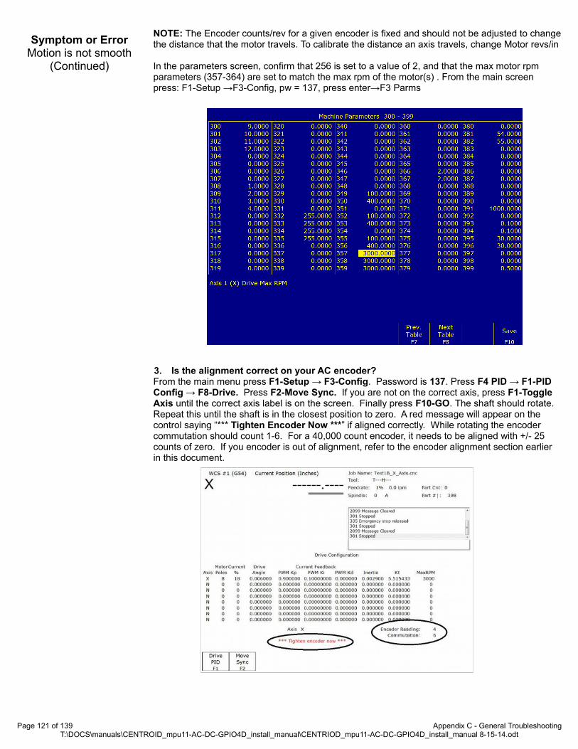
NOTE: The Encoder counts/rev for a given encoder is fixed and should not be adjusted to changethe distance that the motor travels. To calibrate the distance an axis travels, change Motor revs/in
In the parameters screen, confirm that 256 is set to a value of 2, and that the max motor rpm parameters (357-364) are set to match the max rpm of the motor(s) . From the main screen press: F1-Setup →F3-Config, pw = 137, press enter→F3 Parms
3. Is the alignment correct on your AC encoder? From the main menu press F1-Setup → F3-Config. Password is 137. Press F4 PID → F1-PID Config → F8-Drive. Press F2-Move Sync. If you are not on the correct axis, press F1-Toggle Axis until the correct axis label is on the screen. Finally press F10-GO. The shaft should rotate. Repeat this until the shaft is in the closest position to zero. A red message will appear on the control saying “*** Tighten Encoder Now ***” if aligned correctly. While rotating the encoder commutation should count 1-6. For a 40,000 count encoder, it needs to be aligned with +/- 25 counts of zero. If you encoder is out of alignment, refer to the encoder alignment section earlier in this document.
Page 121 of 139 Appendix C - General TroubleshootingT:\DOCS\manuals\CENTROID_mpu11-AC-DC-GPIO4D_install_manual\CENTRIOD_mpu11-AC-DC-GPIO4D_install_manual 8-15-14.odt
Symptom or ErrorMotion is not smooth
(Continued)
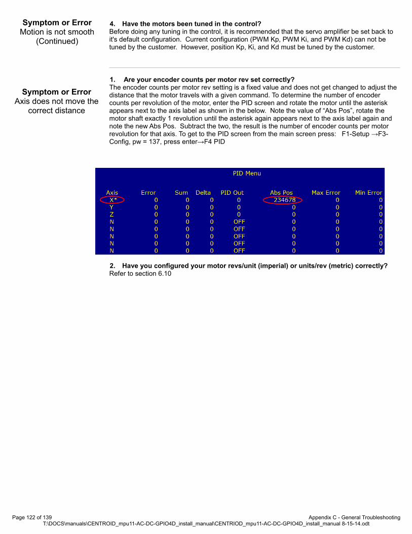
4. Have the motors been tuned in the control?Before doing any tuning in the control, it is recommended that the servo amplifier be set back to it's default configuration. Current configuration (PWM Kp, PWM Ki, and PWM Kd) can not be tuned by the customer. However, position Kp, Ki, and Kd must be tuned by the customer.
1. Are your encoder counts per motor rev set correctly?The encoder counts per motor rev setting is a fixed value and does not get changed to adjust the distance that the motor travels with a given command. To determine the number of encoder counts per revolution of the motor, enter the PID screen and rotate the motor until the asterisk appears next to the axis label as shown in the below. Note the value of “Abs Pos”, rotate the motor shaft exactly 1 revolution until the asterisk again appears next to the axis label again and note the new Abs Pos. Subtract the two, the result is the number of encoder counts per motor revolution for that axis. To get to the PID screen from the main screen press: F1-Setup →F3-Config, pw = 137, press enter→F4 PID
2. Have you configured your motor revs/unit (imperial) or units/rev (metric) correctly? Refer to section 6.10
Page 122 of 139 Appendix C - General TroubleshootingT:\DOCS\manuals\CENTROID_mpu11-AC-DC-GPIO4D_install_manual\CENTRIOD_mpu11-AC-DC-GPIO4D_install_manual 8-15-14.odt
Symptom or ErrorAxis does not move the
correct distance
Symptom or ErrorMotion is not smooth
(Continued)

APPENDIX D - AC/DC TROUBLESHOOTING
The most powerful AC/DC troubleshooting tool is the HSC screen. From the main menu press F7-Utility → F9 Logs → F5 – HSC. The HSC screen shows the state of the AC/DC status bits. This screen is organized by DriveBus channels, therefore the channel number at the top of a column matches LED1 on the AC/DC. The columns are not reorganized if drive drive mapping parameters change.
HSC Screen Bit DefinitionsName Description Notes
BissReceptionErrorsBiSS Encoder Sensor Mode
Reception ErrorsCount of errors during normal running. Counter from 0 to 65535.
BissModeErrorsBiSS Encoder Register Mode
Reception ErrorsCount of errors during setup. Counter from 0 to 65535,
CycloneShutdowns FPGA shutdown counter
The FPGA will shut down under the following conditions: two inter-rupts missed, DSP not started, reprogram enabled, or memory test in progress.
Shutdowns should be 0 during normal operation. Could be caused if drive was interrupted on power up.
If the error is repeatable, it could be the sign of a serious hardwarefailure.
EstimatedBrakeWattageMinimum wattage rating for
brake resistorThis value is updated from the time the drive is turned on until it is powered off.
LoadMeterThe greater of Total current or
Current Request
Current reading shown by the load meters. Typically 0 to 65535, which corresponds to 0-30A for AC/DC-30 and 0-60A for AC/DC-60.
FatalError Fatal error
A serious error has occurred and stopped operation. See other bits for cause of error.
SV_MASTER_ENABLE rising edge in the PLC will clear the fatal error.
Warning Warning bitA condition exists which may become serious, but does not warrant stopping the AC/DC immediately.
ErrorUVWInvalid Commutation invalid stateCommutation tracks are all on or all off. The most common causeis a disconnected encoder. Check the encoder wiring and restart the system.
ErrorUVWBadTransitionCommutation invalid state tran-
sitionCommutation tracks have changed by more than one zone. Check the encoder wiring and restart the system.
ErrorUVWBadSizeIncorrect number of encoder
counts per zoneCounts per zone is incorrect by more than 6.25%. This may also be caused by incorrect encoder counts per revolution setting.
EncoderOK Encoder is ready.For BiSS, good data has been received in the last 0.2 seconds. For quadrature, A and B channels are differential. Check encoder wiring and restart the system.
QuadratureError Encoder invalid state transistionFor quadrature encoder, A and B have changed at the same time. Encoder count is incorrect by at least one count.
EncoderMismatchRequested encoder type does
not match detected typeNot implemented
LineVoltageOn Vm voltage is over 30V DC motor voltage is applied
Page 123 of 139 Appendix D - AC/DC TroubleshootingT:\DOCS\manuals\CENTROID_mpu11-AC-DC-GPIO4D_install_manual\CENTRIOD_mpu11-AC-DC-GPIO4D_install_manual 8-15-14.odt
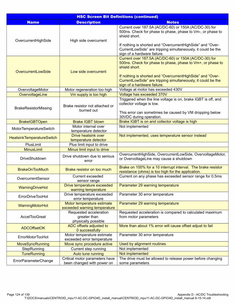
HSC Screen Bit Definitions (continued)Name Description Notes
OvercurrentHighSide High side overcurrent
Current over 187.5A (AC/DC-60) or 150A (AC/DC-30) for 500ns. Check for phase to phase, phase to Vm-, or phase to shield short.
If nothing is shorted and “OvercurrentHighSide” and “Over-CurrentLowSide” are tripping simultaneously, it could be the sign of a hardware failure.
OvercurrentLowSide Low side overcurrent
Current over 187.5A (AC/DC-60) or 150A (AC/DC-30) for 500ns. Check for phase to phase, phase to Vm+, or phase to shield short.
If nothing is shorted and “OvercurrentHighSide” and “Over-CurrentLowSide” are tripping simultaneously, it could be the sign of a hardware failure.
OvervoltageMotor Motor regeneration too high Voltage at motor has exceeded 430VOvervoltageLine Vm supply is too high Voltage has exceeded 370V
BrakeResistorMissingBrake resistor not attached or
burned out
Triggered when the line voltage is on, brake IGBT is off, and collector voltage is low.
This error can sometimes be caused by VM dropping below 30VDC during operation.
BrakeIGBTOpen Brake IGBT blown Brake IGBT is on and collector voltage is high
MotorTemperatureSwitchMotor internal over
temperature detectorNot implemented
HeatsinkTemperatureSwitchDrive heatsink over temperature detector
Not implemented, uses temperature sensor instead
PlusLimit Plus limit input to drive MinusLimit Minus limit input to drive
DriveShutdownDrive shutdown due to serious
error
OvercurrentHighSide, OvercurrentLowSide, OvervoltageMotor,or OvervoltageLine may cause a shutdown
BrakeOnTooMuch Brake resistor on too muchBrake on 100% for a 10 interrupt interval. The brake resistor resistance (ohms) is too high for the application.
OvercurrentSensorCurrent exceeded
sensor rangeCurrent on any phase has exceeded sensor range for 0.5ms
WarningDriveHotDrive temperature exceeded
warning temperatureParameter 29 warning temperature
ErrorDriveTooHotDrive temperature exceeded
error temperatureParameter 30 error temperature
WarningMotorHotMotor temperature estimate
exceeded warning temperatureParameter 29 warning temperature
AccelTooGreatRequested acceleration
greater than physically possible
Requested acceleration is compared to calculated maximum from motor parameters
ADCOffsetOKADC offsets adjusted to
0 successfullyMore than about 1% error will cause offset adjust to fail
ErrorMotorTooHotMotor temperature estimateexceeded error temperature
Parameter 30 error temperature
MoveSyncRunning Move sync procedure active Used by alignment routinesStepRunning Current step running Not implementedTuneRunning Auto tune running Not implemented
ErrorParameterChangeCritical motor parameters havebeen changed with power on
The drive must be allowed to release power before changing some parameters
Page 124 of 139 Appendix D - AC/DC TroubleshootingT:\DOCS\manuals\CENTROID_mpu11-AC-DC-GPIO4D_install_manual\CENTRIOD_mpu11-AC-DC-GPIO4D_install_manual 8-15-14.odt

HSC Screen Bit Definitions (continued)Name Description Notes
CommutationZone Current commutation zone Only applies to AC motors. Refer to the section on encoder alignment for an explanation of motor commutation.
DrivePowerDrive maximum power
indicator1 for AC/DC-60, 0 for AC/DC-30
EncoderType Active encoder type0 for none, 1 for quadrature, 2 for BiSS *not reported at this time*
EstimatedDriveTemperature Drive temperature Temperature reported by heatsink temperature sensorEstimatedMotorTemperature Estimated motor temperature Temperature estimated by AC/DC software routine
PositionErrorSum Sum of error Sum of errorsPidAverage Average of position PID Average of 64 load meter values
Debug counter Subject to change
Upper nibble is drive number. The remaining bits are the num-ber of status packets received, switches to number of bytes re-ceived during firmware update. If the drive is properly commu-nicating with the system this number should be constantly changing. A value
Is the debug counter not counting?• Check LED states• Check “wired input” jumper• Check AC/DC parameters• Power off system for 2 minutes, power the system back on
Updating The AC/DC DSP FirmwareThe AC/DC DSP firmware can be upgraded by the end user.
1. Obtain the latest copy of the AC/DC ac1.hex. This can be obtained by getting the latest version of CNC11 software here Software download (http://ajaxcnc.com/tech/downloads/software/cnc11_windows/current/index.php)
2. Start CNC11 software.3. Press F7-Utility → F9 Logs4. Press alt + F5-HSC simultaneously.5. The HSC menu will open. The debug counter should reset to zero and start counting. After about 30 seconds of counting
the counter should pause for about 10 seconds, then continue counting.
1. NOTE: If the counter does not pause as described above than you already have the most up to date firmware on your AC/DC.
Page 125 of 139 Appendix D - AC/DC TroubleshootingT:\DOCS\manuals\CENTROID_mpu11-AC-DC-GPIO4D_install_manual\CENTRIOD_mpu11-AC-DC-GPIO4D_install_manual 8-15-14.odt

Appendix E - Stock Centroid Encoders
Stock DC Encoders
Encoder Model Centroid Part # Encoder Description Typical Application Encoder Pigtail1.
DynaparF142000/0334X03
34032,000 line, 0 Poles, 5V,
6mm shaft
DC motors in systems not using anAC/DC drive.
Drawing Number S14427
DynaparF142000/0330X03
41272,000 line, 0 Poles, 5V
1/4” shaft
DynaparF182000/0333X09
46552,000 line, 0 Poles, 5V,
1/2” shaft
DynaparF182000/0331X09
28482,000 line, 0 Poles, 5V,
3/8” Shaft
QuantumQR12-10000-0-A-B-D-A-
A6289
10,000 line, 0 Poles, 5V6mm shaft
DC Motors used with the AC/DC drive Drawing Number: S13244Quantum
QR12-10000-0-A-B-L-A-A
703210,0000 line, 0 Pole, 5V,
1/4” shaft
1. Encoder Pigtails: Drawings are for standard pigtails using standard Centroid motors. These drawing might not apply to some rotary tables, retrofits/upgrades, or custom systems.
If you are replacing the encoder pigtail, inspect the condition of the rubber gasket around the MS connector. Worn gaskets need to be replaced. A replacement gasket is Centroid Part Number 4647.
Page 126 of 139 Appendix E - Stock Centroid EncodersT:\DOCS\manuals\CENTROID_mpu11-AC-DC-GPIO4D_install_manual\CENTRIOD_mpu11-AC-DC-GPIO4D_install_manual 8-15-14.odt

Stock AC Encoders
Encoder Model Centroid Part # Encoder Description Typical Application Encoder Pigtail1.
Quantum DevicesQR12-2048-8-A-B-E-A-
A6019
2,048 line, 8 pole, 5V, 8mm shaft
750W, 1KW, and 2KW motors in systemsnot using an AC/DC drive.
For 1KW and largermotors:
Drawing Number: S13244
For 750W Leedan motors:Drawing Number: S13267
Quantum Devices3
QR12-10000-8-A-B-E-A-A
748010,000 line, 8 poles, 5V,
8mm shaftAC Motors used with the AC/DC drive
DynaparF144096/8395A
48144,096 line, 8 pole, 5V,
8mm shaft3kW and 4KW motors in systems not
using an AC/DC drive.Drawing Number: S14427
1. Encoder Pigtails: Drawings are for standard pigtails using standard Centroid motors. These drawing might not apply to some rotary tables, retrofits/upgrades, or custom systems.
If you are replacing the encoder pigtail, inspect the condition of the rubber gasket around the MS connector. Worn gaskets need to be replaced. A replacement gasket is Centroid Part Number 4647.
Page 127 of 139 Appendix E - Stock Centroid EncodersT:\DOCS\manuals\CENTROID_mpu11-AC-DC-GPIO4D_install_manual\CENTRIOD_mpu11-AC-DC-GPIO4D_install_manual 8-15-14.odt

Appendix F - Manual Configuration of AC/DC Motor Parameters
The machine parameters need to be adjusted for your drive before you can use it. Heating coefficients as well as temperature warning and error levels are calculated in imperial units. The machine units must be set to inches from the Control Configuration menu before entering or changing temperature parameters! After saving temperature parameters, the control may be set back to millimeters if desired. Changing the machine units from inches to millimeters will “automatically” convert temperature values.
NOTE: Cooling parameters do not change when switching from inches to millimeters because cooling parameters are calculated as a unit-less value.
To get to the control configuration menu, press F1-Setup. Next, press F3 – Config (The default password is 137), then F1– Contrl. Press F10-Save when finished.
Page 128 of 139 Appendix F - Manual Configuration of AC/DC Motor ParametersT:\DOCS\manuals\CENTROID_mpu11-AC-DC-GPIO4D_install_manual\CENTRIOD_mpu11-AC-DC-GPIO4D_install_manual 8-15-14.odt
Machine Parameters Menu

Recommended ParametersParameter Number Setting Setting Description
21-24 Motor dependent[1] Motor heating coefficients axes 1-4
25-28 Motor dependent[1] Motor cooling coefficients axes 1-4
29 212 (°F) Motor temperature warning
30 260 (°F) Motor temperature error
132-135 Motor dependent[1] Motor heating coefficients axes 5-8
236-239 Motor dependent[1] Motor cooling coefficients axes 5-8
256 2 Drive mode
284-291 Dependent on brake resistor Brake resistor wattage (300 w typical)
300-307 1- 8, Depending on Machine Drive axis mapping
308-315 7 -14, Depending on Machine Encoder assignments
340-347 1.75 Precision mode delay
357-364 Motor Dependent[1] Maximum RPM, may also be set from drive PID screen
374 255 Debug log axis inclustion (bitwise)
375 4000 Debug log size (samples) 0 to 32768
376 1 Data Log collection type: 1= current data, 2=position data
1. See the tables below
Temperature Coefficients for Centroid Motors(Measured in Imperial Units)
SeriesMotor Type
Motor ModelHeating Coefficients
Parameters 21-24Parameters 132-135
Cooling CoefficientsParameters 25-28
Parameters 236-239
SEM AC
Motors(Obsolete)
750 W HDM82E8-76S 156.5817 6.41031 kW HJ130C8-64S 7.9778 3.3333
2 kW HJ130G8-88S 3.0612 2.7778
3 kW HJT155B8-110S 3.4830 2.7778
4 kW HJT155D8-110S 1.3287 2.7778
Faster 4 kW HJT155D8-88S 0.8962 2.7778
Mecapion AC Motors
1.0 kW APM-SE15AXK1-CT2 2.5671 4.5045
2.1 kW APM-SE22A 1.3291 4.0650
2.8 kW APM-SF30G 0.8848 3.3333
2.9 kW APM-SE30AXK3-CT 0.8065 3.7037
4.4 kW APM-SF44G 0.1834 2.7778
Misc Motors Leedan750 W
LDSM85-CS 44.8672 5.5556
Temperature Coefficient for Miscellaneous Motors[1]
(Measured in Imperial Units)
Motor Type
Motor ModelHeating Coefficients
Parameters 21-24Parameters 132-135
Cooling CoefficientsParameters 25-28
Parameters 236-239Barruffaldi 130865/2003 BLQ 43 L 45 SP 55.6205 8.3333
Kollmorgen MT306B1-2184 28.3408 5.3763
Estun 1kW EMG-10APA22 ? ?
Kollmorgen MT504B2-F1B1 8.5001 4.1667
Gettys 16 Type 16-0375-70 0.2199 1.5873
1. This chart contains unsupported motors that successfully work with an AC/DC drive.
Page 129 of 139 Appendix F - Manual Configuration of AC/DC Motor ParametersT:\DOCS\manuals\CENTROID_mpu11-AC-DC-GPIO4D_install_manual\CENTRIOD_mpu11-AC-DC-GPIO4D_install_manual 8-15-14.odt

Temperature Coefficients for Fanuc Motors(Measured in Imperial Units)
SeriesMotorType
Motor ModelHeating Coefficients
Parameters 21-24Parameters 132-135
Cooling CoefficientsParameters 25-28
Parameters 236-239
Fanuc Black End Cap
( Fanuc ● Gettys )
0 A06B-0613-B0xx 4.0135 3.33335 A06B-0614-Bxxx 3.6486 3.030310 A06B-0601-Bxxx 0.5017 1.666720 A06B-0602-Bxxx 0.2527 1.5873
Fanuc YellowEnd Cap
( M Series )
0M A06B-0641-Bxxx 12.3874 0.05745M A06B-0642-Bxxx 7.1351 0.051710M A06B-0651-Bxxx 2.8668 0.036920M A06B-0652-Bxxx 1.1149 0.032330M A06B-0653-Bxxx 0.5902 0.0304
Fanuc S Series Red Cap
&
Fanuc Early Red Cap
0 A06B-0511-Bxxx 11.7374 3.70375 A06B-0512-Bxxx 10.8766 3.333310 A06B-0501-Bxxx 3.4637 2.7778
20MA06B-0505-Bxxx 1.7194 2.5641
20S/150020
A06B-0502-Bxxx 0.9672 2.564120S30 A06B-0503-Bxxx 0.7993 2.5641
30RA06B-0506-Bxxx 0.4600 2.5641
30/200040 A06B-0581-Bxxx 0.2965 1.8519
0-0SP A06B-0374-Bxxx 16.6116 8.33330S A06B-0313-Bxxx 26.4090 3.70375S A06B-0314-Bxxx 14.9505 3.3333
5S/3000 A06B-0514-Bxxx 4.8340 3.33336S A06B-0316-Bxxx 6.3282 3.0303
6S/3000 A06B-0320-Bxxx 4.0692 3.030310S A06B-0315-Bxxx 7.2561 2.7778
10S/3000 A06B-0317-Bxxx 1.7904 2.777820S A06B-0502-B065 0.9969 2.5641
20S/1500 A06B-0505-Bxxx 1.4384 2.564130S A06B-0590-Bxxx 1.5897 2.5641
30/2000 A06B-0506-Bxxx 0.4730 2.5641
Fanuc α (Alpha) Series Red Cap
&
Fanuc αC Series Red Cap[1]
α3/3000 A06B-0123-Bxxx 26.4090 3.7037α6/2000 A06B-0127-Bxxx 16.0374 3.3333α6/3000 A06B-0128-Bx77 5.0293 3.3333α12/2000 A06B-0142-Bxxx 5.4121 2.7778α12/3000 A06B-0143-Bx75 1.7445 2.7778α22/1500 A06B-0146-Bxxx 2.4760 2.5641α22/2000 A06B-0147-Bx75 1.1063 2.5641α30/1200 A06B-0151-Bxxx 2.2628 2.3810α30/2000 A06B-0152-Bxxx 0.8804 2.3810α40/2000 A06B-0157-Bx75 0.4599 2.2222
αC12/2000 A06B-0141-Bx75 12.0400 2.7778αC22/1500 A06B-0145-Bxxx 2.4760 2.5641
Fanuc β (Beta)Series Red Cap
&Fanuc βis Series
Red Cap
β3/3000 A06B-0033-Bxxx 22.3805 4.1667β6/2000 A06B-0034-Bxxx 20.0468 4.1667
β4/4000is A06B-0063-Bx0x 56.9187 8.3333β8/3000is A06B-0075-B203 34.9260 8.3333β12/300is A06B-0078-Bx0x 9.6681 6.6667
β22/2000is A06B-0085-Bx0x 6.5645 5.5556
1. Most Fanuc documentation lists the αC Series as a member of the α Series, while some Fanuc documentation lists the αC Series as a member of the β series.
Page 130 of 139 Appendix F - Manual Configuration of AC/DC Motor ParametersT:\DOCS\manuals\CENTROID_mpu11-AC-DC-GPIO4D_install_manual\CENTRIOD_mpu11-AC-DC-GPIO4D_install_manual 8-15-14.odt
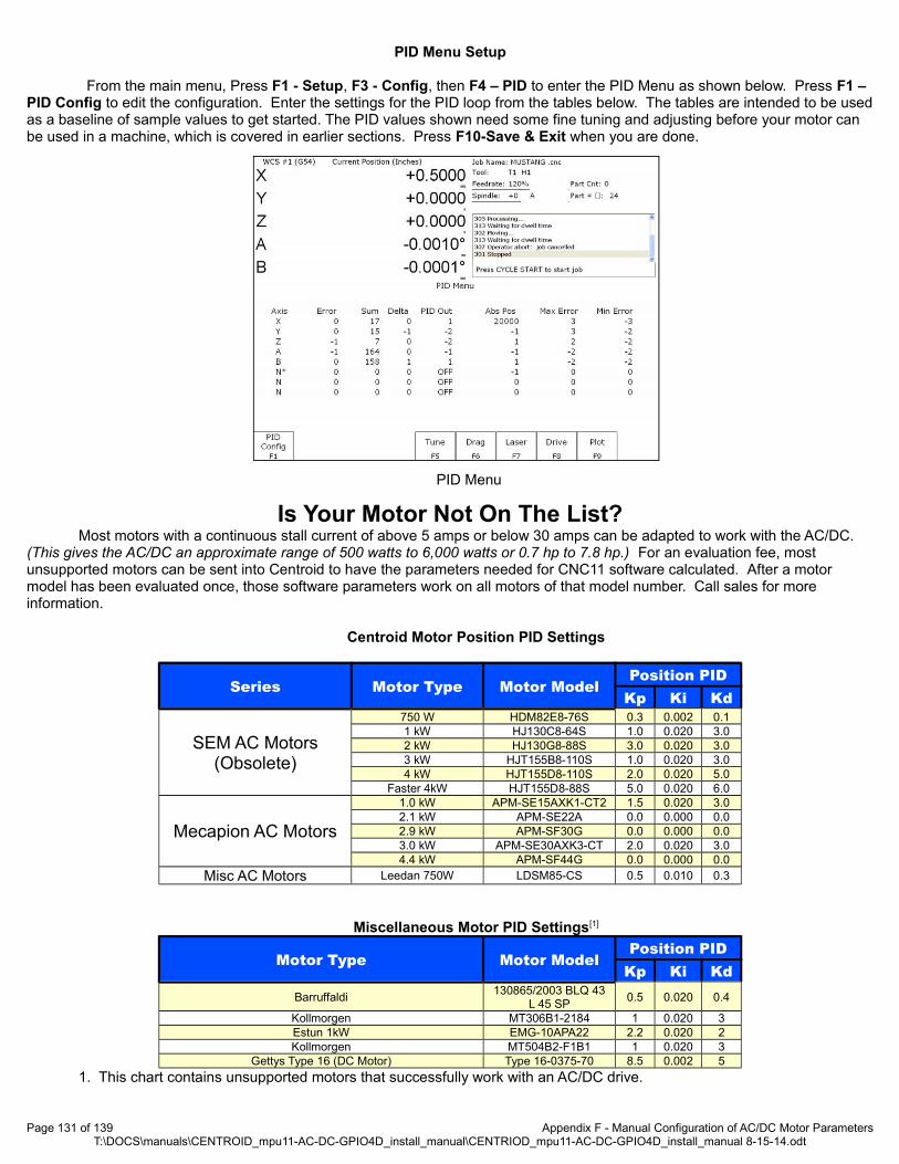
PID Menu Setup
From the main menu, Press F1 - Setup, F3 - Config, then F4 – PID to enter the PID Menu as shown below. Press F1 – PID Config to edit the configuration. Enter the settings for the PID loop from the tables below. The tables are intended to be usedas a baseline of sample values to get started. The PID values shown need some fine tuning and adjusting before your motor can be used in a machine, which is covered in earlier sections. Press F10-Save & Exit when you are done.
Is Your Motor Not On The List?Most motors with a continuous stall current of above 5 amps or below 30 amps can be adapted to work with the AC/DC.
(This gives the AC/DC an approximate range of 500 watts to 6,000 watts or 0.7 hp to 7.8 hp.) For an evaluation fee, most unsupported motors can be sent into Centroid to have the parameters needed for CNC11 software calculated. After a motor model has been evaluated once, those software parameters work on all motors of that model number. Call sales for more information.
Centroid Motor Position PID Settings
Series Motor Type Motor ModelPosition PID
Kp Ki Kd
SEM AC Motors(Obsolete)
750 W HDM82E8-76S 0.3 0.002 0.11 kW HJ130C8-64S 1.0 0.020 3.02 kW HJ130G8-88S 3.0 0.020 3.03 kW HJT155B8-110S 1.0 0.020 3.04 kW HJT155D8-110S 2.0 0.020 5.0
Faster 4kW HJT155D8-88S 5.0 0.020 6.0
Mecapion AC Motors
1.0 kW APM-SE15AXK1-CT2 1.5 0.020 3.02.1 kW APM-SE22A 0.0 0.000 0.02.9 kW APM-SF30G 0.0 0.000 0.03.0 kW APM-SE30AXK3-CT 2.0 0.020 3.04.4 kW APM-SF44G 0.0 0.000 0.0
Misc AC Motors Leedan 750W LDSM85-CS 0.5 0.010 0.3
Miscellaneous Motor PID Settings[1]
Motor Type Motor ModelPosition PID
Kp Ki KdBarruffaldi
130865/2003 BLQ 43L 45 SP
0.5 0.020 0.4
Kollmorgen MT306B1-2184 1 0.020 3Estun 1kW EMG-10APA22 2.2 0.020 2Kollmorgen MT504B2-F1B1 1 0.020 3
Gettys Type 16 (DC Motor) Type 16-0375-70 8.5 0.002 5
1. This chart contains unsupported motors that successfully work with an AC/DC drive.
Page 131 of 139 Appendix F - Manual Configuration of AC/DC Motor ParametersT:\DOCS\manuals\CENTROID_mpu11-AC-DC-GPIO4D_install_manual\CENTRIOD_mpu11-AC-DC-GPIO4D_install_manual 8-15-14.odt
PID Menu

Page 132 of 139 Appendix F - Manual Configuration of AC/DC Motor ParametersT:\DOCS\manuals\CENTROID_mpu11-AC-DC-GPIO4D_install_manual\CENTRIOD_mpu11-AC-DC-GPIO4D_install_manual 8-15-14.odt

SeriesMotorType
Motor ModelPosition PID
Kp Ki Kd
Black End Cap
( Fanuc ●Gettys )
00 A06B-0631-B0xx 1 0.02 10 A06B-0613-B0xx 1.25 0.02 2
5 A06B-0614-Bxxx 1 0.02 3
10 A06B-0601-Bxxx 9 0.02 10
20 A06B-0602-Bxxx 10 0.02 12
Yellow End Cap
( M Series )
00M A06B-0632-Bxxx 0.35 0.005 0.35
0M A06B-0641-Bxxx 1 0.02 1
5M A06B-0642-Bxxx 2 0.02 1.8
10M A06B-0651-Bxxx 9 0.02 7.5
20M A06B-0652-Bxxx 10 0.02 12
30M A06B-0653-Bxxx 10 0.02 12
Fanuc S Series & Early Red Caps
Page 133 of 139 Appendix F - Manual Configuration of AC/DC Motor ParametersT:\DOCS\manuals\CENTROID_mpu11-AC-DC-GPIO4D_install_manual\CENTRIOD_mpu11-AC-DC-GPIO4D_install_manual 8-15-14.odt
Motor Type Motor ModelPosition PID
Kp Ki Kd0 A06B-0511-Bxxx 2 0.02 35 A06B-0512-Bxxx 2 0.02 510 A06B-0501-Bxxx 5 0.02 7
20MA06B-0505-Bxxx 10 0.02 12
20S/150020
A06B-0502-Bxxx 10 0.02 1220S30 A06B-0503-Bxxx 10 0.02 12
30RA06B-0506-Bxxx 10 0.02 12
30/200040 A06B-0581-Bxxx 10 0.02 12
0-0SP A06B-0374-Bxxx 2 0.02 30S A06B-0313-Bxxx 2 0.02 35S A06B-0314-Bxxx 2 0.02 3
5S/3000 A06B-0514-Bxxx 2 0.02 36S A06B-0316-Bxxx 3 0.02 5
6S/3000 A06B-0320-Bxxx 3 0.02 510S A06B-0315-Bxxx 5 0.02 7
10S/3000 A06B-0317-Bxxx 5 0.02 720S A06B-0502-B065 10 0.02 12
20S/1500 A06B-0505-Bxxx 10 0.02 1230S A06B-0590-Bxxx 10 0.02 12
30/2000 A06B-0506-Bxxx 10 0.02 12
Fanuc α and β Motors
Fanuc DC Motors
Series Motor Type Motor ModelPosition PID
Kp Ki Kd
α (Alpha)Series
&
αC Series[2]
α3/3000 A06B-0123-Bxxx 1 0.02 1α6/2000 A06B-0127-Bxxx 2 0.02 3α6/3000 A06B-0128-Bxxx 3 0.02 5α12/2000 A06B-0142-Bxxx 3 0.02 5α12/3000 A06B-0143-Bxxx 5 0.02 7α22/1500 A06B-0146-Bxxx 10 0.02 12α22/2000 A06B-0147-Bxxx 10 0.02 12α30/1200 A06B-0151-Bxxx 10 0.02 12α30/2000 A06B-0152-Bxxx 10 0.02 12α40/2000 A06B-0157-Bxxx 10 0.02 12
αC12/2000 A06B-0141-Bxxx 7 0.02 9αC22/2000 A06B-0145-Bxxx 10 0.02 12
β (Beta) Series
&
βis Series
β3/3000 A06B-0033-Bxxx 1 0.02 1β6/2000 A06B-0034-Bxxx 2 0.02 1.8
β4/4000is A06B-0063-Bx0x 1 0.02 1β8/3000is A06B-0075-B203 2 0.02 1.8β12/300is A06B-0078-Bx0x 5 0.02 7β22/2000is A06B-0085-Bx0x 10 0.02 12

Drive Configuration Setup
From the main menu, press F1 - Setup, F3 - Config, F4 - PID, and then F8 – Drive to enter the Drive Configuration menu. Press F1 – Drive PID to edit the configuration. Enter the settings for the current feedback PID loop from the tables below. Press F10-Accept when you are done.
Centroid Motors
SeriesMotorType
Motor Model
Current PID
Poles ACDC-30Current
ACDC-60Current
Angle Kp Ki KdInertiaIn-lbsec2
KtMaxRPM
SEM ACMotors
(Obsolete)
750W HDM82E8-76S 8 20%Not Rec-
om-mended
0.020 2.50 0.10 0 0.0009 5.64 3,900
1kW HJ130C8-64S 8 100% 50% 0.007 2.50 0.10 0 0.0140 4.67 4,000
2kW HJ130G8-88S 8Not
Recommended80% 0.008 2.00 0.10 0 0.0230 6.36 3,400
3kW HJT155B8-110S 8Not
Recommended80% 0.013 5.00 0.10 0 0.0290 8.06 2,727
4kW HJT155D8-110S 8Not
Recommended100% 0.015 3.00 0.10 0 0.0480 8.06 2,727
Faster4kW
HJT155D8-88S 8Not
Recommended100% 0.000 3.00 0.08 0 0.0480 6.38 3,400
Mecapion AC Motors
1kW APM-SE15AXK1-CT2 8 67% 34% 0.007 1.50 0.10 0 0.0106 5.25 5,000
2.1kW APM-SE22A 8Not
Recommended80% TBD TBD TBD TBD 0.0154 5.27 5,000
2.8kW APM-SF30G 8Not
Recommended76% 0.000 2.50 0.08 0 0.0410 7.52 3,000
2.9kW APM-SE30AXK3-CT 8Not
Recommended85% 0.000 1.50 0.07 0 0.0201 5.00 5,000
4.4kW APM-SF44G 8Not
Recommended100% 0.000 1.50 0.04 0 0.0654 5.95 3,000
Misc MotorsLeedan0750W
LDSM85-CS 8 36% 18% 0.006 0.90 0.10 0 0.0029 5.52 3,000
Miscellaneous Motors[1]
Motor Type Motor ModelCurrent PID
Poles ACDC-30Current
ACDC-60Current
Angle Kp Ki KdInertia
In-lb sec2 KtMaxRPM
Barruffaldi130865/2003 BLQ 43
L 45 SP6 43% 22% 0.008 2.50 0.10 0 0.0040 3.70 4,500
Kollmorgen MT306B1-2184 8 67% 34% 0.000 1.50 0.12 0 0.0010 5.40 4,600
Estun 1kW EMG-10APA22 8 100% 50% 0.000 1.50 0.12 0 0.0161 6.70 3,000
Kollmorgen MT504B2-F1B1 100% 50% 0.000 1.50 0.12 0 0.0161 6.70 3,000
Gettys Type 16 (DC Motor) Type 16-0375-70 0Not
Recommended100% 0.000 1.50 0.12 0 0.2750 6.73 2,000
1. This chart contains unsupported motors that successfully work with an AC/DC drive.
Page 134 of 139 Appendix F - Manual Configuration of AC/DC Motor ParametersT:\DOCS\manuals\CENTROID_mpu11-AC-DC-GPIO4D_install_manual\CENTRIOD_mpu11-AC-DC-GPIO4D_install_manual 8-15-14.odt

Fanuc DC Motors
End CapColor
MotorType Motor Model
Current PIDPoles (ACDC-30)
Current(ACDC-60)
CurrentAngle Kp Ki Kd
InertiaIn-lb sec2 Kt
MaxRPM
Black
( Fanuc ● Gettys )
0 A06B-0613-B0xx May Need Evaluated[1]
5 A06B-0614-Bxxx 0 80% 40% 0 2.00 0.100 0 0.0434 4.23 2,000
10 A06B-0601-BxxxMay Need Evaluated[1]
20 A06B-0602-Bxxx
Yellow
( M Series )
0M A06B-0641-Bxxx 0 Not Recommended 100% 0 2.00 0.100 0 0.0220 3.73 2,000
5M A06B-0642-Bxxx 0 60% 30% 0 6.00 0.100 0 0.0320 5.80 2,000
10M A06B-0651-Bxxx 0 80% 40% 0 3.50 0.100 0 0.1130 8.85 1,500
20M A06B-0652-BxxxMay Need Evaluated[1]
30M A06B-0653-Bxxx
Fanuc S Series & Early Red Caps
Motor Type Motor Model
Current PID
Pol
es ACDC-30Current
ACDC-60Current
Angle Kp Ki KdInertia
In-lb sec2 KtMaxRPM
0 A06B-0511-Bxxx May Need Evaluated[1]
5 A06B-0512-Bxxx 8 70% 35% 0.006 2.00 0.100 0 0.0570 7.64 2,00010 A06B-0501-Bxxx
May Need Evaluated[1]20MA06B-0505-Bxxx
20S/150020
A06B-0502-Bxxx 8 Not Recommended 100% 0.000 2.50 0.080 0 0.1476 10.42 2,00020S30 A06B-0503-Bxxx
May Need Evaluated[1]
30RA06B-0506-Bxxx
30/200040 A06B-0581-Bxxx
0-0SP A06B-0374-Bxxx0S A06B-0313-Bxxx5S A06B-0314-Bxxx
5S/3000 A06B-0514-Bxxx6S A06B-0316-Bxxx
6S/3000 A06B-0320-Bxxx10S A06B-0315-Bxxx
10S/3000 A06B-0317-Bxxx20S A06B-0502-B065
20S/1500 A06B-0505-Bxxx30S A06B-0590-Bxxx
30/2000 A06B-0506-Bxxx
1. May Need Evaluated: Evaluated motors have the software parameters needed for Centroid CNC11 software. For unevaluatedmotors, the customer may need to ship a motor to Centroid for evaluation. The evaluation process will provide the customer with the CNC11 software parameters. After a motor model has been evaluated once, those software parameters work on all motors of that model number. Call sales for more information.
Page 135 of 139 Appendix F - Manual Configuration of AC/DC Motor ParametersT:\DOCS\manuals\CENTROID_mpu11-AC-DC-GPIO4D_install_manual\CENTRIOD_mpu11-AC-DC-GPIO4D_install_manual 8-15-14.odt

Fanuc α and β Motors
Series Motor Type Motor Model
Current PID
Pol
es ACDC-30Current
ACDC-60Current
Angle Kp Ki KdInertia
In-lb sec2 KtMaxRPM
α (Alpha) Series
&
αC Series[2]
α3/3000 A06B-0123-BxxxMay Need Evaluated[1]
α6/2000 A06B-0127-Bxxxα6/3000 A06B-0128-Bxxx 8 100% 50% 0.003 1.50 0.050 0 0.0234 5.31 4000
α12/2000 A06B-0142-Bxxx
May Need Evaluated[1]
α12/3000 A06B-0143-Bxxxα22/1500 A06B-0146-Bxxxα22/2000 A06B-0147-Bxxxα30/1200 A06B-0151-Bxxxα30/2000 A06B-0152-Bxxxα40/2000 A06B-0157-Bxxx
αC12/2000 A06B-0141-Bxxx 8 60% 30% 0.010 4.00 0.075 0 0.0555 18.06 2000αC22/1500 A06B-0145-Bxxx
May Need Evaluated[1]β (Beta) Series
&
βis Series
β3/3000 A06B-0033-Bxxxβ6/2000 A06B-0034-Bxxx
β4/4000is A06B-0063-Bx0xβ8/3000is A06B-0075-B203 8 60% 30% 0.001 2.50 0.100 0 0.0103 10.27 3,000β12/300is A06B-0078-Bx0x
May Need Evaluated[1]β22/2000is A06B-0085-Bx0x
1. May Need Evaluated: Evaluated motors have the software parameters needed for Centroid CNC11 software. For unevaluatedmotors, the customer may need to ship a motor to Centroid for evaluation. The evaluation process will provide the customer with the CNC11 software parameters. After a motor model has been evaluated once, those software parameters work on all motors of that model number. Call sales for more information.
Page 136 of 139 Appendix F - Manual Configuration of AC/DC Motor ParametersT:\DOCS\manuals\CENTROID_mpu11-AC-DC-GPIO4D_install_manual\CENTRIOD_mpu11-AC-DC-GPIO4D_install_manual 8-15-14.odt

Appendix G - Compatible Motors(Motor Torque, HP, and Wattage)
What if your motor is not on the list?Most motors with a continuous stall current of above 5 amps or below 30 amps can be adapted to work with the AC/DC. (This gives the AC/DC an approximate range of 500 watts to 6,000 watts or 0.7 hp to 7.8 hp.) For an evaluation fee, most unsupported motors can be sent into Centroid to have the parameters needed for CNC11 software calculated. After a motor model has been evaluated once, those software parameters work on all motors of that model number. Call sales for more information.
Centroid Motors[1]
Series Motor Type Motor Model Max RPMContinuous
Torque(in lb)
PeakTorque (in lb)
MechanicalHorsepower(Imperial)[2]
Power (kW)[2]
RatedRPM[2]
SEM ACMotors
(Obsolete)
750W HDM82E8-76S 3,900 13 33.8 0.45 0.34 2,200
1kW HJ130C8-64S 4,000 33.5 140.0 1.41 1.05 2,500
2kW HJ130G8-88S 3,400 71.3 305.5 2.04 1.52 1,800
3kW HJT155B8-110S 2,727 84.6 386.9 1.21 0.90 900
4kW HJT155D8-110S 2,727 137.0 483.7 2.61 1.95 1,200
Faster 4kW HJT155D8-88S 3,400 132.1 383.0 4.40 3.28 2,100
MecapionAC Motors
1 kW APM-SE15AXK1-CT2 5,000 57.8 105.6 2.75 2.95 3,000
2.1 kW APM-SE22A 5,000 84.3 252.9 2.67 1.99 2,000
2.8 kW APM-SF30G 3,000 120.2 343.1 2.86 2.13 1,500
3.9 kW APM-SE30AXK3-CT 5,000 105.0 225.1 5.00 3.73 3,000
4.4k W APM-SF44G 3,000 182.6 356.8 4.35 3.24 1,500
Misc Motors Leedan 750W LDSM85-CS 3,000 22.1 59.6 0.70 0.52 2,200
1. The numbers in this chart are calculated from the motor manufacturer data sheets. Centroid has not verified these numbers.
2. Motor power and motor mechanical horsepower in this chart is calculated at rated RPM, not maximum RPM. A better estimationof torque and power can be provided by the “Centroid AC/DC Setup Wizard” software, which is explained in section 3.3.
Unsupported Motors[1]
Motor Type Motor Model Max RPMContinuous
Torque(in lb)
PeakTorque (in lb)
MechanicalHorsepower(Imperial)[2]
Power (kW)[2]
RatedRPM[2]
Barruffaldi 130865/2003 BLQ 43 L 45 SP 4,500 16.3 47.7 1.16 0.87
Kollmorgen MT306B1-2184 4,600 28.9 108.5 2.11 1.57
Estun 1kW EMG-10APA22 3,000 42.3 126.9 1.34 1.00 2,000
Kollmorgen MT504B2-F1B1 3,000 57.6 201.0 2.74 2.05
Gettys Type 16 (DC motor) Type 16-0375-70 2,000 222.1 403.8 7.05 5.26
1. This chart contains unsupported motors that successfully work with an AC/DC drive.
2. Motor power and motor mechanical horsepower in this chart is calculated from rated RPM. If nothing is listed in the “rated RPM” column, then the motors rated RPM is the same as maximum RPM. A better estimation of torque and power can be provided by the “Centroid AC/DC Setup Wizard” software, which is explained in section 3.3.
Page 137 of 139 Appendix G - Compatible MotorsT:\DOCS\manuals\CENTROID_mpu11-AC-DC-GPIO4D_install_manual\CENTRIOD_mpu11-AC-DC-GPIO4D_install_manual 8-15-14.odt

Fanuc DC Motors[1]
End Cap Color
MotorType
MotorModel
Max RPMContinuous
Torque(in lb)
PeakTorque (in lb)
MechanicalHorsepower(Imperial)[2]
Power (kW)[2]
Black
(Fanuc●Gettys)
00 A06B-0631-Bxxx 2,000 8.7 18.2 0.2 0.15
0 A06B-0613-Bxxx 2,000 25.4 50.8 0.5 0.4
5 A06B-0614-Bxx 2,000 50.8 101.5 1 0.8
10 A06B-0601-Bxxx 1,500 113.3 226.6 2 1.1
20 A06B-0602-Bxxx 1,500 222.6 404.6 2.5 1.8
Yellow
(M Series)
00 A06B-0632-Bxxx 2,000 8.8 17.6 0.2 0.15
0M A06B-0641-Bxxx 2,000 26.9 56.0 0.5 0.4
5M A06B-0642-Bxxx 2,000 52.2 104.4 1 0.8
10M A06B-0651-B012 1,500 106.2 212.4 1.5 1.1
20M A06B-0652-Bxxx 1,500 203.1 406.2 2.5 1.8
30M A06B-0653-Bxxx 1,200 333.3 666.6 4 2.8
1. The numbers in this chart are calculated from the Fanuc motor data sheets. Centroid has not verified these numbers. See the Centriod Fanuc CNC Retrofit Installation Manual for more information about adapting these motors to work on a Centroid System
3. Motor power and motor mechanical horsepower in this chart is calculated at rated RPM, which is the same as maximum RPM for the drives listed in this chart. A better estimation of torque and power can be provided by the “Centroid AC/DC Setup Wizard” software, which is explained in section 3.3.
Page 138 of 139 Appendix G - Compatible MotorsT:\DOCS\manuals\CENTROID_mpu11-AC-DC-GPIO4D_install_manual\CENTRIOD_mpu11-AC-DC-GPIO4D_install_manual 8-15-14.odt

Fanuc AC Motors[1]
SeriesMotorType
Motor Model Max RPMContinuous
Torque (in lb)
PeakTorque (in lb)
MechanicalHorsepower(Imperial)[2]
Power (kW)[2]
RatedRPM[2]
S series
&
EarlyRedCaps
0-0SP A06B-0374-Bxxx 3,000 26.2 72.2 0.67 0.50S A06B-0313-Bxxx 3,000 26.1 68.0 1.0 0.755S A06B-0314-Bxxx 2,000 51.8 134.1 1.2 0.9
5S/3000 A06B-0514-Bxxx 3,000 51.5 151.3 1.3 1.06S A06B-0316-Bxxx 2,000 78.2 220.8 1.26[3] 0.94[3]
6S/3000 A06B-0320-Bxxx 3,000 78.2 221.3 1.70[3] 1.27[3]
10S A06B-0315-Bxxx 2,000 103.6 286.2 2.4 1.810S/3000 A06B-0317-Bxxx 3,000 104.3 306.7 3.1 2.320S/1500
A06B-0505-Bxxx 1,500 198.9 582.0 3.8 2.820M20S
A06B-0502-Bxxx 2,000 198.8 605.4 4.7 3.520
20S/3000 A06B-0318-Bxxx 3,000 200.9 366.4 4.7 3.530S A06B-0590-Bxxx 1,200 330.0 951.9 4.4 3.3
30/2000A06B-0506-Bxxx 2,000 260.7 547.0 5.4 4.0
30R30S/3000 A06B-0319-Bxxx 3,000 261.8 456.7 6.0 4.4
40 A06B-0581-Bxxx 1,200 494.5 966.5 4.8 3.60 A06B-0511-Bxxx 2,000 25.8 78.4 0.79 0.65 A06B-0512-Bxxx 2,000 51.9 160.4 1.2 0.9
10 A06B-0501-Bxxx 2,000 105.0 315.1 2.4 1.830 A06B-0503-Bxxx 1,200 324.6 885.3 4.4 3.3
α (Alpha)Series
&
αC Series
α3/3000 A06B-0123-Bxxx 3,000 26.5 69.0 1.3 0.9α6/2000 A06B-0127-Bxxx 2,000 53.5 160.6 1.4 1.0α6/3000 A06B-0128-Bxxx 4,000 53.1 159.3 1.9 1.4 3,000
α12/2000 A06B-0142-Bxxx 2,000 105.9 317.8 2.8 2.1α12/3000 A06B-0143-Bxxx 3,000 105.6 306.7 3.8 2.8α22/1500 A06B-0146-Bxxx 1,500 194.7 579.5 4.0 3.0α22/2000 A06B-0147-Bxxx 2,000 193.6 559.2 5.0 3.8α22/3000 A06B-0148-Bxxx 3,000 193.2 361.1 5.9 4.4α30/1200 A06B-0151-Bxxx 1,200 264.3 792.9 4.4 3.3α30/2000 A06B-0152-Bxxx 2,000 264.6 785.9 6.7 4.5α30/3000 A06B-0153-Bxxx 3,000 265.5 472.6 7.1 4.8
α40/2000A06B-0157-Bxxx
(without fan)2,000 334.6 743.5 7.8 5.9
αC12/2000 A06B-0141-Bxxx 2,000 106.5 325.0 1.4 1 1,000αC22/1500 A06B-0145-Bxxx 1,500 194.7 579.5 2.1 1.5
β (Beta)Series
&βis
Series
β3/3000 A06B-0033-Bxxx 3,000 26.3 74.3 0.7 0.5β6/2000 A06B-0034-Bxxx 3,000 52.0 139.4 1.2 0.9 2,000
β4/4000is A06B-0063-Bxxx 4,000 31.2 79.7 1 0.75β8/3000is A06B-0075-Bxxx 3,000 61.6 184.8 1.6 1.2 2,000
β12/3000is A06B-0078-Bxxx 3,000 97.5 286.8 2.4 1.8
β22/2000is A06B-0085-Bxxx 2,000 177.0 470.0 3.4 2.5
1. The numbers in this chart are calculated from the Fanuc motor data sheets. Centroid has not verified these numbers. See the Centriod Fanuc CNC Retrofit Installation Manual for more information about adapting these motors to work on a Centroid System
2. Motor power and motor mechanical horsepower in this chart is calculated from rated RPM. If nothing is listed in the “rated RPM” column, then the motors rated RPM is the same as maximum RPM. A better estimation of torque and power can be provided by the “Centroid AC/DC Setup Wizard” software, which is explained in section 3.3.
3. Data sheet information on Hp and Kw power could not be found; instead these numbers are calculated from torque specifications.
Page 139 of 139 Appendix G - Compatible MotorsT:\DOCS\manuals\CENTROID_mpu11-AC-DC-GPIO4D_install_manual\CENTRIOD_mpu11-AC-DC-GPIO4D_install_manual 8-15-14.odt


