William Mattison III - Dare we hope our students believe.pdf
Upload
diane-nicholsCategory
view
227download
2
MPD 575 Design for XDesign for Retool
Brian Armstrong and Kim CallowayEdits by Dwayne Mattison, Keith Wanrer, Mac Lunn
Edits by Rolf Glaser

22
Design for Retool
• Introduction to DFR• Heuristics• Key Principles of DFR• Procedures for DFR• Examples• Conclusion

3
Introduction to DFR
What is Design for Retool?• To reequip with tools ~ Webster• To revise and reorganize, especially for the
purpose of updating or improving~ The Free Dictionary
• Utilize existing capital facilities / equipment to produce (manufacture / assemble) new and improved products ~ Kim and Brian

4
Introduction to DFR (cont)
Why Design for Retool?
• Easier to make running changes / incremental improvements• Use Make Like Production (MLP) prototype requirements as
process is well defined• It’s often the only option if late changes are required or if late
decisions drive component changes which in turn affect process• Saves money; return on capital investment, less manufacturing
engineering resource investment • Reduces engineering risk as process failure modes are well
understood• Shorten development time; faster time to market

5
Introduction to DFR (cont)
What are the drawbacks of Design for Retool?• Can limit design flexibility on all new designs for numerous
reasons• Undesirable component characteristics are sometimes carried
forward because they are too costly in terms of process change to correct
• Can create apathy in the product development process where components and processes that are understood to be carry-over will not be assessed and lead to new issues
• Business risk that competition is using newer / better process methods obtaining edge in performance, quality and cost
• Old equipment and all the associated concerns with its use

66
Design for Retool
• Introduction to DFR• Heuristics• Key Principles of DFR• Procedures for DFR• Examples• Conclusion
7
DFR Heuristics
• If it’s not broke then don’t fix it (but do maintain it or it will break!)
• The more knowledgeable the component engineer is with the current process the better the potential for incremental product improvements given the constraints of the current process
• Late design changes are more difficult to deal with than up front engineering assumption related changes

88
Design for Retool
• Introduction to DFR• Heuristics• Key Principles of DFR• Procedures for DFR• Examples• Conclusion
9
DFR Principles• What are the processes used to manufacture a
component?
• How is the assembly process ordered?
• How are assemblies transferred from one station to another?
• How are components located and oriented?
• What tools and processes are used to manufacture the part?

10
DFR PrinciplesComponent:
• Carry forward the Best in Class design features
• Eliminate unnecessary part features that can negatively impact tooling designs
• Minimize machining stock
• Standardize handling and assembly features
• Manage tolerances to insure they are not over applied
Process:
• Eliminate unneeded processes
• Minimize repositioning and multiple fixture where possible
• Utilize capability data from existing process to ‘keep’ what works well and improve processes where capability is a concern.
11
DFR Principles• Plan to reuse process and tooling where possible
• Verify manufacturing requirement during the design phase to avoid unique manufacturing constraints
• Note: sometimes the offsets are to be found on a sub-system or system level. Balance of ‘real estate’, cost, weight or consumption
1212
Design for Retool
• Introduction to DFR• Heuristics• Key Principles of DFR• Procedures for DFR• Examples• Conclusion
13
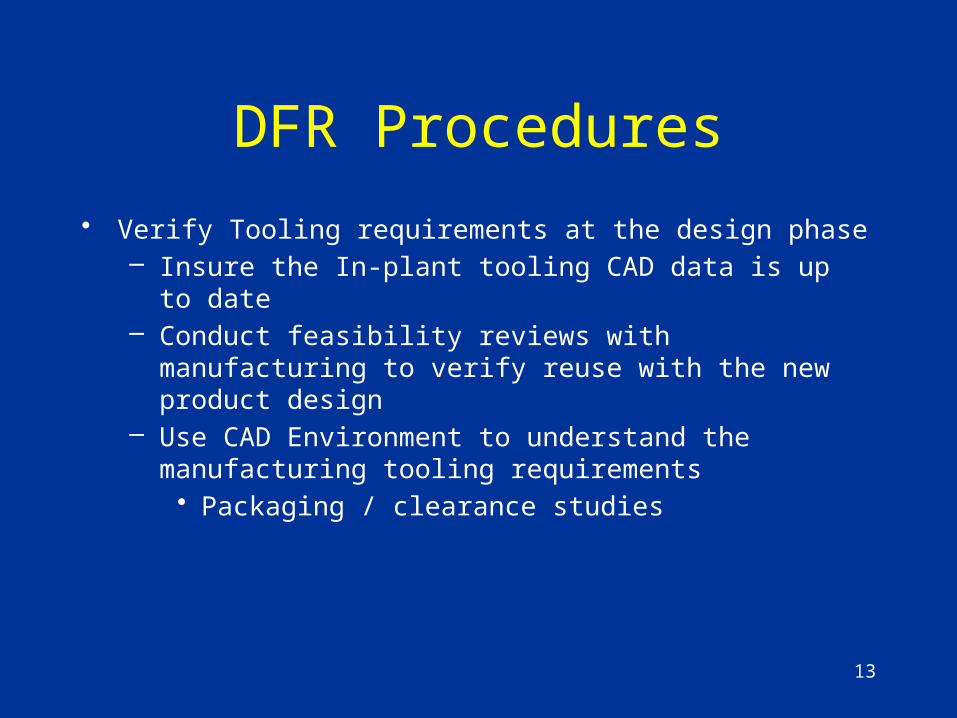
DFR Procedures
• Verify Tooling requirements at the design phase– Insure the In-plant tooling CAD data is up to date– Conduct feasibility reviews with manufacturing to verify
reuse with the new product design– Use CAD Environment to understand the manufacturing
tooling requirements• Packaging / clearance studies
14
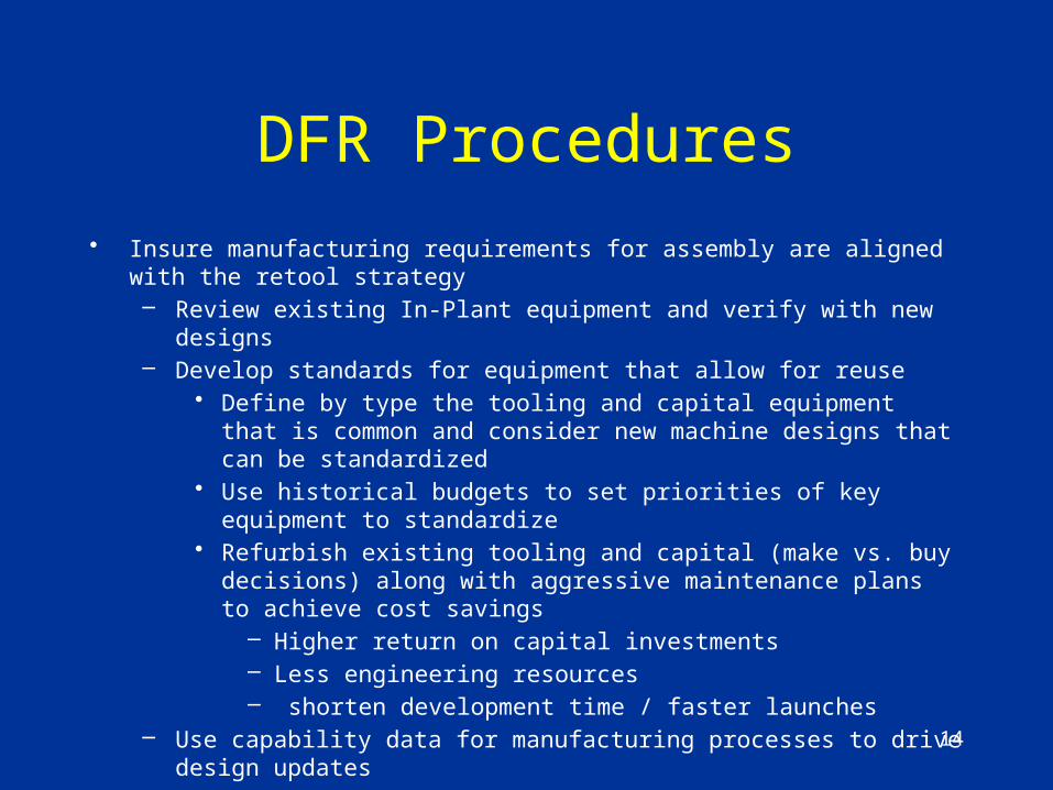
• Insure manufacturing requirements for assembly are aligned with the retool strategy– Review existing In-Plant equipment and verify with new designs– Develop standards for equipment that allow for reuse
• Define by type the tooling and capital equipment that is common and consider new machine designs that can be standardized
• Use historical budgets to set priorities of key equipment to standardize• Refurbish existing tooling and capital (make vs. buy decisions) along
with aggressive maintenance plans to achieve cost savings – Higher return on capital investments– Less engineering resources– shorten development time / faster launches
– Use capability data for manufacturing processes to drive design updates– Revise and update existing manufacturing processes
DFR Procedures

15
DFR Procedures
• Verify current In-Plant processes are capable to meet new design requirements– Verify the existing process can be applied to new
concepts– Apply best in class designs and processes to new
designs– Apply assembly process lessons learned to new
product designs

16
DFR Procedures
• Use semi-production tooling (a.k.a. Production pull-a-head or Make like Production) in a production environment to develop the assembly process and support late programming timing– Use production tooling with limited capabilities to support production timing
or develop manufacturing process• Limited capabilities include Aluminum vs. Steel • Manual clamps vs. hydraulic or pneumatic cylinders• Operator instruction vs. electronic Poka yoke systems• Use CMM holding fixtures in place of Attribute gauges• Use milling processes that are more expensive to support limited runs• Use of simi-completed equipment to can reduce build timing by 40%• Process capabilities can be updated and corrected in the design
• Use Prototype tooling in a production environment to develop the assembly process and support late programming timing– Prototype tooling used for process prove-out can be used to mature the
design and support launch timing but the tools will have a limited manufacturing life and may not meet all manufacturing requirements
1717
Design for Retool
• Introduction to DFR• Heuristics• Key Principles of DFR• Procedures for DFR• Examples• Conclusion

18
DFR Procedures Make Like Production
Once improvements are made to a component the new design must be verified. There are many prototype phases in product development process where components must be MLP.

19
CAD of Coyote Engine in Shipping Rack
10.9mm CLEARANCE - OIL FILTER TO SHIPPING RACK
2C3E-6A642-BB OIL COOLER
P415
AA5E-6714-AA

20
MLP (Engine Engineering)• Early prototypes (pre-VP), rapid prototyping, early
concepts, and MLP can be supported in-house at Ford.
• Engine Manufacturing Development Operations (EMDO)– EMDO uses process that simulate production process to produce
engine components– Process Sequence– Material Removal Rates (wet/dry)– Same locating Datums– Fixtures
• Beech Daly Technical Center (BDTC)– Inspection/Gauging methods and programs– Assembly methods

21
Examples
• Connecting Rod• Engine Oil Cooler
22
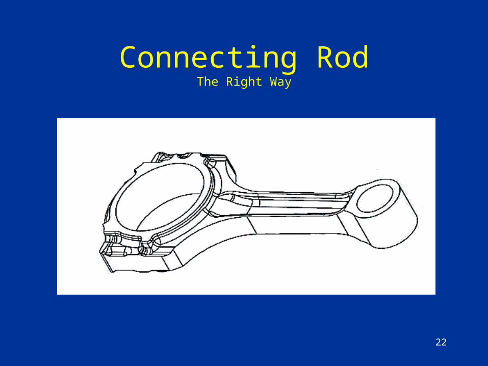
Connecting RodThe Right Way
23
Connecting RodThe Right Way
Increased engine speeds and increased engine specific output (HP/L) drives needed design changes to connecting rod.
• Need increase strength while simultaneously reducing rod weight
• Need to use the existing rod machining line
24
Connecting RodThe Right Way
Rod Improvements:• Material change from Powdered Metal to Forged Steel
– Allows use of less material for weight reduction and is stronger than PM
• Maintain critical features for current process– Rod shoulders for part transfer– Clamping pads, pin-end radius for locating and rod cap gnorf
• Other functional improvements:– Rolled threads to allow blind holes for weight reduction
• Lower stress concentrations• Eliminate potential for chips in bolt hole
– Elimination of Piston Pin Bushing• Reduces weight further• Reduces part count and cost
– Tapered Pin End for weight reduction (Piston, Crank as well)

25
Connecting RodThe Right Way
The changes to the connecting rod necessitated some changes to the process as follows:
• The harder material required changes to boring, drilling, and grinding operations
• Speed and feeds had to be adjusted• Fracture splitting of rod required laser notch
in lieu of the traditional machining broach– The laser equipment was installed where the old
broach equipment was removed– Some UAW push-back due to Health and Safety
concerns
26
Connecting RodThe Right Way
Summary:All of the changes to the connecting rod were
containable via retooling the existing manufacturing line. The improvements to the connecting rod help the overall engine system. The result is a lighter, stronger rod that in turn allows for weight reduction of the piston and crank shaft. Reducing the rotating and reciprocating mass in the engine which improves the overall engine efficiency.

27
Engine Oil CoolerThe Wrong Way
Background:In the spring of 2008 at FMC Engine
Engineering. Coyote V8 engine program is in the M1D phase of GPDS with S197 as lead customer and P415 as the secondary but higher volume customer.
– Preliminary testing indicates engine oil temps are marginal
– Lubrication CPMT and Systems Engineer are concerned and request to package protect for an engine oil cooler
– Coyote program manager denies the request to package protect for the oil cooler stating “this engine doesn’t need an oil cooler”

OIL COOLER INTERFERES WITH ALTERNATOR
OIL COOLER INTERFERES WITH DRIP SHIELD
16.26mm OIL COOLER CLEARANCE TO FRAME RAIL
11.5MM CLEARANCE COOLER TO BELT (NOT INCLUDING SLAP)
Engine Oil Cooler
29
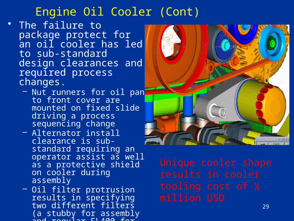
Engine Oil Cooler (Cont)• The failure to package
protect for an oil cooler has led to sub-standard design clearances and required process changes.– Nut runners for oil pan to front
cover are mounted on fixed slide driving a process sequencing change
– Alternator install clearance is sub-standard requiring an operator assist as well as a protective shield on cooler during assembly
– Oil filter protrusion results in specifying two different filters (a stubby for assembly and regular FL400 for service)
– EPSA cable rerouted– Redesigned OFA to support
additional weight of cooler
Unique cooler shape results in cooler tooling cost of ½ million USD
30
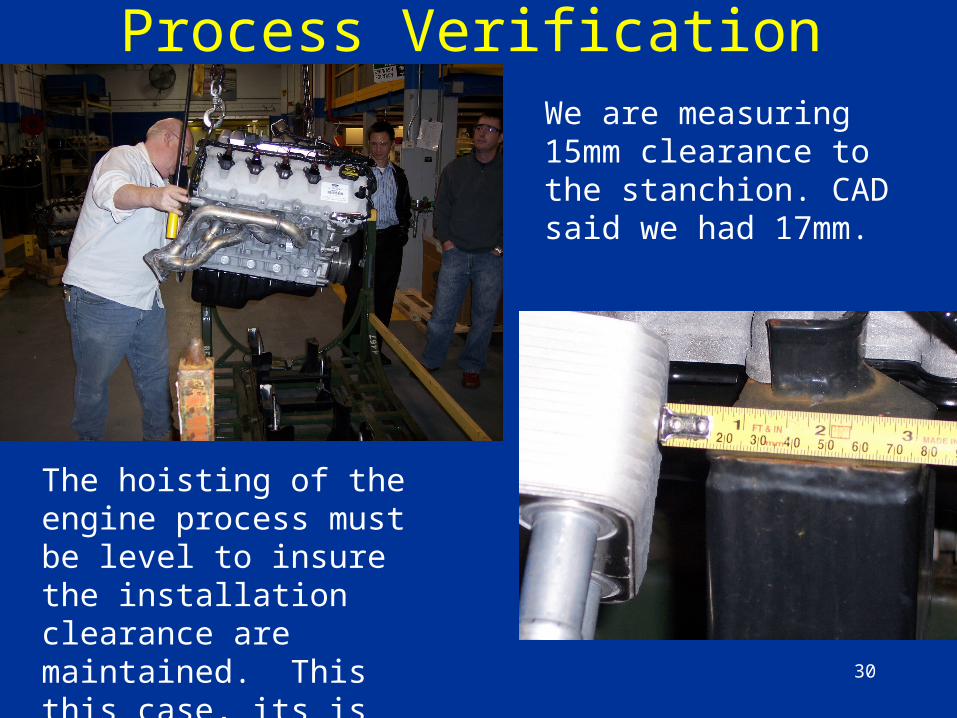
Process Verification
The hoisting of the engine process must be level to insure the installation clearance are maintained. This this case, its is not.
We are measuring 15mm clearance to the stanchion. CAD said we had 17mm.
31
Engine Oil Cooler (Cont)Valley Mounted Cooler
If an engine oil cooler was part of the original engineering assumptions, then more time and resources would have been available to design a product that utilizes the current process without all of the sub-standard clearances and process tear-ups.
A valley mounted cooler would package nicely, but would require more time to sort through the block casting and block retooling changes.
32
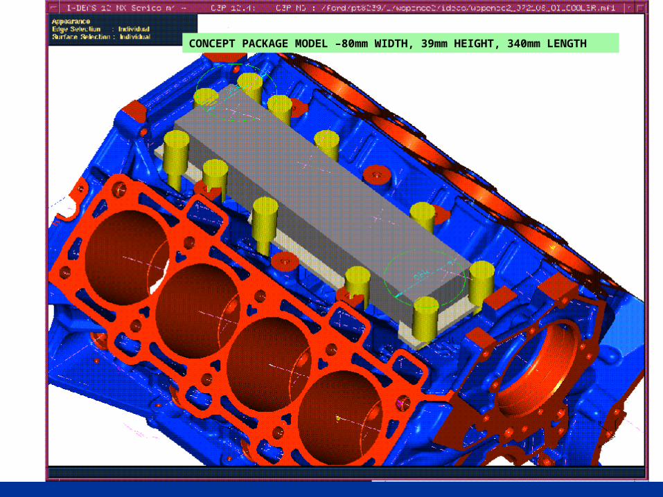
CONCEPT PACKAGE MODEL –80mm WIDTH, 39mm HEIGHT, 340mm LENGTH
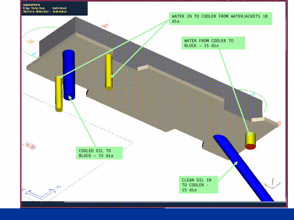
CLEAN OIL IN TO COOLER - 15 dia
COOLED OIL TO BLOCK – 15 dia
WATER IN TO COOLER FROM WATERJACKETS 10 dia
WATER FROM COOLER TO BLOCK – 15 dia

34
Engine Oil Cooler (Cont)Valley Mounted Cooler
• This package holds more promise than the external OFA mounted cooler previously shown.
• Larger cooler capacity with better heat rejection• Less coolant and oil pressure loss• Package constraints limited to intake, knock sensors
and wire harness• Fewer water / oil terminations reducing risk of leaks• Requires more Retooling effort and higher cost for
the larger cooler

3535
Design for Retool
• Introduction to DFR• Heuristics• Key Principles of DFR• Procedures for DFR• Examples• Conclusion
36
Conclusion
Engineers who are responsible for the design and release of components should understand the whole manufacturing process related to their component and their system. Similarly, engineers should know the manufacturing process to understand what is currently possible, what is good about the current process and what they would change if they could.