MP-Series Low Inertia Motors - KVC Industrial Supplies …€¦ · · 2016-07-30MP-Series Low...
16
Rockwell Automation Publication GMC-SG001Q-EN-P - April 2011 21 Rotary Motion Chapter 1 MP-Series Low Inertia Motors MP-Series low-inertia (Bulletin MPL), high output brushless servo motors utilize innovative design characteristics to reduce motor size while delivering significantly higher torque. These compact and highly dynamic brushless servo motors are designed by Allen-Bradley to meet the demanding requirements of high performance motion systems. For drive compatibility, refer to Servo Drives on page 14 . MP-Series Low Inertia Motor High Resolution Encoder Features MP-Series low-inertia motors are available with high performance encoders with a choice of Single-turn (-E, -S) or Multi-turn (-V, -M) high resolution feedback. • Up to 2 million counts per revolution (-M and -S) for smooth performance (MPL-A/B3xx, MPL-A/B4xx, MPL-A/B45xx, MPL-A/B5xx, MPL-B6xx, MPL-B8xx, and MPL-B9xx motors). • Up to 260 thousand counts per revolution (-E and -V) for smooth performance (MPL-A/B15xx and MPL-A/B2xx motors). • Single-turn encoder provides high-resolution absolute position feedback within one turn. • Multi-turn encoder provides high-resolution absolute position feedback within 4096 turns. The electromechanical design does not require a battery. Motor Connector/Cable Compatibility MP-Series (Bulletin MPL) motors are equipped with threaded and SpeedTec-ready DIN connectors. For information on transitioning your Bulletin MPL motor installation from bayonet cables to circular DIN cables, refer to 2090-Series Motor Power and Feedback Transition Cables on page 400 . • MPL-A/B3xxx…MPL-B9xxx motors • Receives M4 and M7 cable plugs (remove the O-ring for M7) • Attach M7 cable plug with one-quarter turn • Attach M4 cable plug with 5…6 turns SpeedTec-ready DIN Connectors O-ring SpeedTec DIN (M7) Cable Plug • 2090-CFBM7DF-CEAAxx (standard) flying-lead, feedback cables • 2090-CFBM7DD-CEAAxx (standard) drive-end connector, feedback cables • 2090-CFBM7DF-CEAFxx (continuous-flex) flying-lead, feedback cables • 2090-CFBM7DD-CEAFxx (continuous-flex) drive-end connector, feedback cables • 2090-CFBM7DF-CDAFxx (continuous-flex) flying-lead, feedback cables • 2090-CPWM7DF-xxAAxx (standard) power-only cables • 2090-CPBM7DF-xxAAxx (standard) power/brake cables • 2090-CPWM7DF-xxAFxx (continuous-flex) power-only cables • 2090-CPBM7DF-xxAFxx (continuous-flex) power/brake cables • MPL-A/B15xxx…MPL-A/B2xxx motors • Receives M4 cable plugs only • Attach M4 cable plug with 5…6 turns • 2090-XXNFMF-Sxx (standard) feedback cables • 2090-CFBM4DF-CDAFxx (continuous-flex) feedback cables • 2090-XXNPMF-Sxx (standard) power cables • 2090-CPWM4DF-16AFxx (continuous-flex) power-only cables • 2090-CPBM4DF-16AFxx (continuous-flex) power-with-brake cables Threaded DIN Connectors Threaded DIN (M4) Cable Plug
-
Upload
trinhthuan -
Category
Documents
-
view
234 -
download
0
Transcript of MP-Series Low Inertia Motors - KVC Industrial Supplies …€¦ · · 2016-07-30MP-Series Low...

Rockwell Automation Publication GMC-SG001Q-EN-P - April 2011 21
Rotary Motion Chapter 1
MP-Series Low Inertia Motors
MP-Series low-inertia (Bulletin MPL), high output brushless servo motors utilize innovative design characteristics to reduce motor size while delivering significantly higher torque. These compact and highly dynamic brushless servo motors are designed by Allen-Bradley to meet the demanding requirements of high performance motion systems.
For drive compatibility, refer to Servo Drives on page 14.
MP-Series Low Inertia Motor High Resolution Encoder Features
MP-Series low-inertia motors are available with high performance encoders with a choice of Single-turn (-E, -S) or Multi-turn (-V, -M) high resolution feedback.
• Up to 2 million counts per revolution (-M and -S) for smooth performance (MPL-A/B3xx, MPL-A/B4xx, MPL-A/B45xx, MPL-A/B5xx, MPL-B6xx, MPL-B8xx, and MPL-B9xx motors).
• Up to 260 thousand counts per revolution (-E and -V) for smooth performance (MPL-A/B15xx and MPL-A/B2xx motors).
• Single-turn encoder provides high-resolution absolute position feedback within one turn. • Multi-turn encoder provides high-resolution absolute position feedback within 4096 turns. The electromechanical
design does not require a battery.
Motor Connector/Cable Compatibility
MP-Series (Bulletin MPL) motors are equipped with threaded and SpeedTec-ready DIN connectors.
For information on transitioning your Bulletin MPL motor installation from bayonet cables to circular DIN cables, refer to 2090-Series Motor Power and Feedback Transition Cables on page 400.
• MPL-A/B3xxx…MPL-B9xxx motors• Receives M4 and M7 cable plugs
(remove the O-ring for M7)• Attach M7 cable plug with one-quarter turn• Attach M4 cable plug with 5…6 turns
SpeedTec-readyDIN Connectors
O-ring SpeedTec DIN (M7) Cable Plug
• 2090-CFBM7DF-CEAAxx (standard) flying-lead, feedback cables• 2090-CFBM7DD-CEAAxx (standard) drive-end connector, feedback cables• 2090-CFBM7DF-CEAFxx (continuous-flex) flying-lead, feedback cables• 2090-CFBM7DD-CEAFxx (continuous-flex) drive-end connector, feedback cables• 2090-CFBM7DF-CDAFxx (continuous-flex) flying-lead, feedback cables• 2090-CPWM7DF-xxAAxx (standard) power-only cables• 2090-CPBM7DF-xxAAxx (standard) power/brake cables• 2090-CPWM7DF-xxAFxx (continuous-flex) power-only cables• 2090-CPBM7DF-xxAFxx (continuous-flex) power/brake cables
• MPL-A/B15xxx…MPL-A/B2xxx motors• Receives M4 cable plugs only• Attach M4 cable plug with 5…6 turns
• 2090-XXNFMF-Sxx (standard) feedback cables• 2090-CFBM4DF-CDAFxx (continuous-flex) feedback cables• 2090-XXNPMF-Sxx (standard) power cables• 2090-CPWM4DF-16AFxx (continuous-flex) power-only cables• 2090-CPBM4DF-16AFxx (continuous-flex) power-with-brake cables
ThreadedDIN Connectors
Threaded DIN (M4) Cable Plug

22 Rockwell Automation Publication GMC-SG001Q-EN-P - April 2011
Chapter 1 Rotary Motion
MP-Series Low Inertia Motor Options
MP-Series low-inertia motors are available with these options:• 24V DC brake.• Shaft seal kit available for field installation. Shaft seals are made of nitrile. Kits include a lubricant to reduce wear. • Optional keyless shaft available in limited frame sizes with extended lead times (MPL-A/B3xx,
MPL-A/B4xx, MPL-A/B45xx, and MPL-A/B5xx motors).
Motor Shaft Seal Kit Combinations and Dimensions
Motor Series Shaft Seal Cat. No.Inside Diametermm (in.)
Outside Diametermm (in.)
Widthmm (in.)
MPL-A15xx and MPL-B15xxMPL-SSN-F63F75 12 (0.47) 24 (0.95) 7 (0.28)
MPL-A2xx and MPL-B2xx
MPL-A3xx and MPL-B3xx MPL-SSN-A3B3 17 (0.67) 47 (1.85) 7 (0.28)
MPL-A4xx and MPL-B4xx MPL-SSN-A4B4 20 (0.79) 52 (2.05) 7 (0.28)
MPL-A45xx and MPL-B45xx MPL-SSN-A5B5 25 (0.98) 62 (2.44) 7 (0.28)
MPL-A520 and MPL-B520MPL-A540 and MPL-B540MPL-A560 and MPL-B560
MPL-SSN-F165 30 (1.18) 72 (2.83) 8 (0.31)
MPL-B580 MPL-SSN-F165-32MM 35 (1.38) 72 (2.83) 8 (0.31)
MPL-B6xx MPL-SSN-A6B6 40 (1.57) 90 (3.54) 8 (0.31)
MPL-B8xx MPL-SSN-A8B8 45 (1.77) 75 (2.95) 8 (0.31)
MPL-B9xx MPL-SSN-A9B9 52 (2.05) 72 (2.83) 8 (0.31)

Rockwell Automation Publication GMC-SG001Q-EN-P - April 2011 23
Rotary Motion Chapter 1
MP-Series Low Inertia Motor Performance Specifications
MP-Series Low Inertia Motor (230V) Performance Specifications
System Combinations (230V)
MotorMPL-
Max Speedrpm
Continuous Stall TorqueNm (lb-in)
PeakStall TorqueNm (lb-in)
Motor Rated OutputkW
Speed at Motor Rated Outputrpm
Rotor Inertia (1)
kg-m2 (lb-in-s2)
(1) Refer to MP-Series Low Inertia Motor Brake Specifications on page 25 for Brake Rotor Inertia and Brake Motor Weight.
Motor Weight, approx. (1)
kg (lb)
A1510V 8000 0.26 (2.3) 0.77 (6.8) 0.16 8000 0.0000074 (0.000065) 1.0 (2.2)
A1520U 7000 0.49 (4.3) 1.58 (14) 0.27 7000 0.000013 (0.00012) 1.2 (2.6)
A1530U 7000 0.90 (8.0) 2.80 (25) 0.39 7000 0.000023 (0.00020) 1.6 (3.4)
A210V 8000 0.55 (4.9) 1.50 (13.5) 0.37 8000 0.000015 (0.00013) 1.4 (3.1)
A220T 6000 1.61 (14.2) 4.74 (42) 0.62 6000 0.000039 (0.00035) 2.0 (4.4)
A230P 5000 2.10 (18.6) 8.20 (73) 0.86 5000 0.000063 (0.00056) 2.6 (5.7)
A310P 5000 1.58 (14) 3.61 (32) 0.73 47500.000044 (0.00039) 2.7 (5.8)
A310F 3000 1.58 (14) 3.61 (32) 0.46 3000
A320P 5000 3.05 (27) 7.91 (70) 1.3 47500.000078 (0.00069) 3.7 (8.0)
A320H 3500 3.05 (27) 7.91 (70) 1.0 3350
A330P 5000 4.18 (37) 11.1 (98) 1.8 5000 0.00012 (0.0010) 4.6 (10)
A420P 5000 4.74 (42) 10.2 (90) 2.0 5000 0.00026 (0.0023) 4.3 (9.4)
A430P 5000 5.99 (53) 19.8 (175) 2.2 50000.00038 (0.0033) 5.5 (12)
A430H 3500 6.21 (55) 19.8 (175) 1.8 3500
A4530K 4000 8.13 (72) 20.3 (180) 2.5 40000.00040 (0.0036) 7.3 (16)
A4530F 2800 8.36 (74) 20.3 (180) 1.9 2800
A4540C 1500 10.2 (90) 27.1 (240) 1.5 15000.00052 (0.0046) 8.6 (19)
A4540F 3000 10.2 (90) 27.1 (240) 2.6 3000
A4560F 3000 14.1 (125) 34.4 (305) 3.0 3000 0.00078 (0.0067) 11.82 (26)
A520K 4000 10.7 (95) 24.3 (215) 3.5 3500 0.000783 (0.0069) 9.8 (21.5)
A540K 4000 19.4 (172) 48.6 (430) 5.5 4000 0.00147 (0.013) 15.0 (33)
A560F 3000 26.8 (237) 61.0 (540) 5.3 3000 0.00213 (0.019) 20.2 (44.5)
For MP-Series Low Inertia Motors and Refer to
Kinetix 6000 (230V) drives page 515
Kinetix 2000 (230V) drives page 561
Kinetix 300 (240V) drives page 597
Ultra3000/5000 (230V) drives (1)
(1) MPL-A15xxx and MPL-A2xxx motors are not compatible with Ultra5000 drives. All other MPL-Axxxx motors are compatible with both Ultra3000 and Ultra5000 drives.
page 629

24 Rockwell Automation Publication GMC-SG001Q-EN-P - April 2011
Chapter 1 Rotary Motion
MP-Series Low Inertia Motor (460V) Performance Specifications
MotorMPL-
Max Speedrpm
Continuous Stall TorqueNm (lb-in)
PeakStall TorqueNm (lb-in)
Motor Rated OutputkW
Speed at Motor Rated Outputrpm
Rotor Inertia (1)
kg-m2 (lb-in-s2)
(1) Refer to MP-Series Low Inertia Motor Brake Specifications on page 25 for Brake Rotor Inertia and Brake Motor Weight.
Motor Weight, approx. (1)
kg (lb)
B1510V 8000 0.26 (2.3) 0.77 (6.8) 0.16 8000 0.0000074 (0.000065) 1.0 (2.2)
B1520U 7000 0.49 (4.3) 1.58 (14) 0.27 7000 0.000013 (0.00012) 1.2 (2.6)
B1530U 7000 0.90 (8.0) 2.80 (25) 0.39 7000 0.000023 (0.00020) 1.6 (3.4)
B210V 8000 0.55 (4.9) 1.50 (13.5) 0.37 8000 0.000015 (0.00013) 1.4 (3.1)
B220T 6000 1.61 (14.2) 4.74 (42) 0.62 6000 0.000039 (0.00035) 2.0 (4.4)
B230P 5000 2.10 (18.6) 8.20 (73) 0.86 5000 0.000063 (0.00056) 2.6 (5.7)
B310P 5000 1.58 (14) 3.61 (32) 0.77 5000 0.000044 (0.00039) (2)
(2) Rotor inertia may vary slightly depending on feedback.
2.7 (5.8)
B320P 5000 3.05 (27) 7.91 (70) 1.5 5000 0.000078 (0.00069) (2) 3.7 (8.0)
B330P 5000 4.18 (37) 11.1 (98) 1.8 5000 0.00012 (0.0010) (2) 4.6 (10)
B420P 5000 4.74 (42) 13.5 (120) 1.9 5000 0.00026 (0.0023) (2) 4.3 (9.4)
B430P 5000 6.55 (58) 19.8 (175) 2.2 5000 0.00038 (0.0033) (2) 5.5 (12)
B4530F 3000 8.25 (73) 20.3 (180) 2.1 30000.00040 (0.0036) (2) 7.3 (16)
B4530K 4000 8.25 (73) 20.3 (180) 2.6 4000
B4540F 3000 10.2 (90) 27.1 (240) 2.6 3000 0.00052 (0.0046) (2) 8.6 (19)
B4560F 3000 14.1 (125) 34.4 (305) 3.2 3000 0.00078 (0.0067) (2) 11.82 (26)
B520K 4000 10.7 (95) 23.2 (205) 3.5 3500 0.000783 (0.0069) 9.8 (21.5)
B540D 2000 19.4 (172) 41.0 (362) 3.4 2000 0.00147 (0.013)15 (33)
B540K 4000 19.4 (172) 48.6 (430) 5.4 4000 0.00147 (0.013)
B560F 3000 26.8 (237) 67.8 (600) 5.5 3000 0.00213 (0.019) 20.2 (44.5)
B580F 3000 34.0 (301) 87.0 (770) 7.1 30000.00289 (0.023) 25.4 (56)
B580J 3800 34.0 (301) 81.0 (716) 7.9 3800
B640F 3000 36.7 (325) 72.3 (640) 6.11 2000 0.004 (0.0354) 26.8 (59)
B660F 3000 48.0 (425) 101.1 (895) 6.15 2000 0.0058 (0.051) 35.0 (77)
B680D 2000 62.8 (556) 154.2 (1365) 9.3 20000.00775 (0.0685) 40.4 (89)
B680F 3000 60.0 (531) 108.5 (960) 7.5 2000
B860D 2000 83.0 (735) 152.5 (1350) 12.5 2000 0.0169 (0.150) 57.3 (126)
B880C 1500 110.0 (973) 203 (1800) 12.6 15000.0224 (0.198) 72.7 (160)
B880D 2000 110.0 (973) 147 (1300) 12.6 2000
B960B 1200 130.0 (1150) 231 (2050) 12.7 1200
0.0273 (0.242) 76.0 (167)B960C 1500 124.3 (1100) 226 (2000) 14.8 1500
B960D 2000 124.3 (1100) 226 (2000) 15.0 2000
B980B 1000 162.7 (1440) 278 (2460) 15.2 1000
0.0354 (0.313) 94.5 (208) B980C 1500 158.2 (1400) 271 (2400) 16.8 1500
B980D 2000 158.2 (1400) 260 (2300) 18.6 2000
B980E 2750 141.0 (1250) 237 (2100) 13.0 1500
Rockwell Automation Publication GMC-SG001Q-EN-P - April 2011 25
Rotary Motion Chapter 1
System Combinations (460V)
MP-Series Low Inertia Motor Brake Specifications
For MP-Series Low Inertia Motors and Refer to
Kinetix 6000 and Kinetix 6200/6500 (460V) drives page 521
Kinetix 7000 drives page 583
Kinetix 300 (480V) drives page 602
Ultra3000/5000 (460V) drives (1)
(1) MPL-B15xxx and MPL-B2xxx motors are not compatible with Ultra5000 drives. All other MPL-Bxxxx motors are compatible with both Ultra3000 and Ultra5000 drives.
page 635
MotorMPL-
Max Backlash (brake engaged)arc minutes
Holding TorqueNm (lb-in)
Coil Currentat 24V DCA
Brake Response Time
Brake Rotor Inertiakg-m2 (lb-in-s2)
Brake Motor Weight, approx.kg (lb)
Releasems
Engage (using external arc suppression device)
MOV ms Diode ms
A/B1510V
0
0.9 (8.0) 0.43…0.53 23 9 18
0.0000099 (0.000088) 1.2 (2.6)
A/B1520U 0.000015 (0.00013) 1.4 (3.1)
A/B1530U 0.000026 (0.00023) 1.8 (3.9)
A/B210V
4.5 (40) 0.46…0.56 58 20 42
0.000033 (0.00029) 1.8 (4.0)
A/B220T 0.000057 (0.00050) 2.4 (5.4)
A/B230P 0.000082 (0.00073) 3.0 (6.7)
A/B310
45 4.18 (37) 0.45…0.55 50 20 110
0.000057 (0.00050) 3.7 (8)
A/B320 0.000092 (0.00081) 4.6 (10)
A/B330 0.00013 (0.0011) 5.6 (12.4)
A/B420
37 10.2 (90) 0.576…0.704 110 25 160
0.00030 (0.0027) 6.0 (13.2)
A/B430 0.00042 (0.0038) 7.3 (16)
A/B4530 0.00044 (0.0039) 9.1 (20)
A/B4540 0.00056 (0.0050) 11.0 (24)
A/B4560 0.00084 (0.0072) 15.1 (33.2)
A/B520
25 28.3 (250) 1.05…1.28 70 50 250
0.000897 (0.0079) 12.38 (27.25)
A/B540 0.00157 (0.0139) 17.6 (38.75)
A/B560 0.00227 (0.020) 22.8 (50.1)
B580 0.0030 (0.026) 29.0 (63.8)
B640
25
70.0 (619) 1.91…2.19 200 120 900
0.00438 (0.03863) 37.27 (82.0)
B660 0.00628 (0.0555) 42.95 (94.5)
B680 0.0079 (0.0698) 50.8 (112.0)
B860106.0 (938) 2.05…2.50 250 200 1000
0.0177 (0.1570) 72.7 (160)
B880 0.0232 (0.205) 87.7 (193)
B960 153.0 (1350) 3.85…4.70 300 200 1200
0.0290 (0.256) 89.5 (197)
B980 0.0378 (0.334) 116.5 (256)
26 Rockwell Automation Publication GMC-SG001Q-EN-P - April 2011
Chapter 1 Rotary Motion
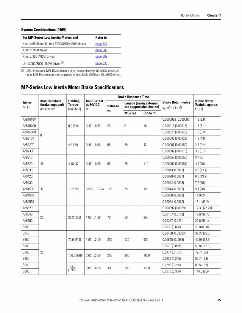
MP-Series Low Inertia Motor Dimensions
MPL-A/B15xx and MPL-A/B2xx Motor Dimensions (threaded DIN connectors)
LB
T
L-LB
D
L
LE
F
G
N
PLA
HDAD
53.9(2.12) LD
See Detail A
2.8 ±0.30(0.110 ±0.012)
Shaft Detail with Key
Shaft Diameter TolerancesMPL-A/B1510, -A/B1520, -A/B1530 Motors:Ø 8.998…9.007 (0.3543…0.3546)
MPL-A/B210, -A/B220, -A/B230 Motors:Ø 10,997…11.008 (0.4330…0.4334)
Detail A
ShaftDiameter
MPL-A/B1510, -A/B1520, -A/B1530 andMPL-A/B210, -A/B220, -A/B230 Motors:
Ø 11.89…11.95 (0.468…0.470)
MPL-A/B1510, -A/B1520, -A/B1530 = 3 x 3 x 14 KeyMPL-A/B210, -A/B220, -A/B230 = 4 x 4 x 16 Key
Optional Shaft SealRefer to page 22
for MP-Series small frame motor
shaft seal kit information.
Power/Brake Connector
FeedbackConnector
S Diameter Holes onM Diameter Bolt Circle
Dimensions are in mm (in.)
Shaft End Threaded HoleMPL-A/B1510, -A/B1520, -A/B1530 Motors:Thread - M3 x 0.5-6HThread Depth - 9.0 (0.35)MPL-A/B210, -A/B220, -A/B230 Motors:Thread - M4 x 0.7-6HThread Depth - 10.0 (0.39)
Connector housings may berotated within a range of 180°
Pilot Diameter TolerancesMPL-A/B1510, -A/B1520, -A/B1530 Motors:
Ø 39.995…40.011 (1.5746…1.5752)MPL-A/B210, -A/B220, -A/B230 Motors:
Ø 59.993…60.012 (2.3619…2.3627)
Shaft, Pilot, and Keyway Tolerances MPL-A/B15xx MPL-A/B2xx
Shaft Runout (T.I.R.) 0.030 (0.0012) 0.035 (0.0014)
Pilot Eccentricity (T.I.R.) 0.08 (0.0031) 0.08 (0.0031)
Max Face Runout (T.I.R.) 0.08 (0.0031) 0.08 (0.0031)
Keyway Depth (G) 7.10…7.20(0.280…0.283)
8.40…8.50(0.331…0.335)
Keyway Width (F) 2.971…2.996(0.117…0.118)
3.97…4.00(0.156…0.157)

Rockwell Automation Publication GMC-SG001Q-EN-P - April 2011 27
Rotary Motion Chapter 1
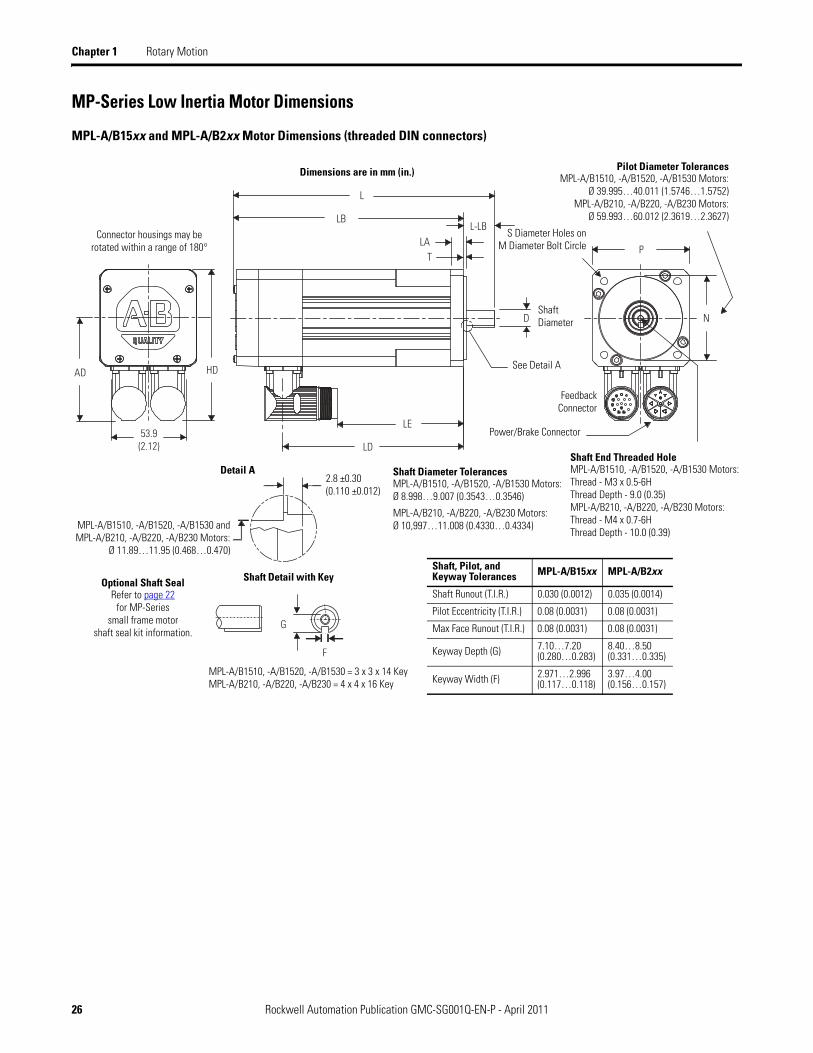
MPL-A/B15xx and MPL-A/B2xx Motor Dimensions (threaded DIN connectors)
Motors are designed to metric dimensions. Inch dimensions are approximate conversions from millimeters. Dimensions without tolerances are for reference.
MotorSeriesMPL-Aor MPL-B
ADmm (in.)
HDmm (in.)
Tmm (in.)
LAmm (in.)
LD (1)
mm (in.)
(1) If ordering an MPL-A/B1510, A/B1520, or A/B1530 motor with brake, add 36.1 mm (1.421 in.) to dimension L and LB, and add 33.4 mm (1.32 in.) to LD and LE.If ordering an MPL-A/B210, A/B220, or A/B230 motor with brake, add 39.0 mm (1.535 in.) to dimension L and LB, and add 24.7 mm (0.97 in.) to LD and LE.
LE (1)
mm (in.)
L (1)
mm (in.)
LB (1)
mm (in.)
L-LB (2)
mm (in.)
(2) Tolerance for this dimension is ±0.7 mm (±0.028 in.).
Dmm (in.)
Mmm (in.)
S (3)
mm (in.)
(3) Tolerance for this dimension is +0.3 mm (+0.012 in.).
Nmm(in.)
Pmm (in.)
Gmm (in.)
Fmm (in.)
1510
66.5(2.62)
94.0(3.70)
2.50(0.098)
9.0(0.35)
78.3(3.08)
39.2(1.54)
133.2(5.25)
113.5(4.47)
19.7(0.776)
9.0(0.35)
63.0(2.480)
5.80(0.228)
40.0(1.57)
55.0(2.17)
7.2(0.283)
3.0(0.118)1520 91.3
(3.60)52.4(2.06)
146.2(5.76)
126.5(4.98)
1530 116.3(4.58)
77.2(3.04)
171.2(6.74)
151.5(5.96)
210
74.0(2.91)
109(4.29)
2.50(0.098)
9.0(0.35)
78.6(3.09)
39.6(1.56)
137.3(5.40)
114.6(4.51)
22.7(0.894)
11.0(0.43)
75.0(2.953)
5.80(0.228)
60.0(2.36)
70.0(2.76)
8.5(0.335)
4.0(0.157)220 104.1
(4.10)65.1(2.56)
162.8(6.41)
140.1(5.52)
230 129.6(5.10)
90.6(3.57)
188.3(7.41)
165.6(6.52)

28 Rockwell Automation Publication GMC-SG001Q-EN-P - April 2011
Chapter 1 Rotary Motion
MPL-A/B3xx, MPL-A/B4xx, MPL-A/B45xx, MPL-A/B5xx Motor Dimensions (SpeedTec DIN connectors)
N
PLA
LB
T
L-LB
AD
HD
D
L
LD
F
GE
MPL
-A/B
3xx
= 66
.1 (2
.60)
MPL
-A/B
4xx
= 67
.7 (2
.66)
MPL
-A/B
45xx
= 6
7.7
(2.6
6)M
PL-B
520,
-B54
0, -B
560
= 68
.2 (2
.68)
LE
End
Cap
MPL
-A52
0,M
PL-A
540,
MPL
-A56
0,M
PL-B
580
71.2
(2.8
0)
LEAD
HD
See
Deta
il A
Pilo
t Dia
met
er T
oler
ance
sM
PL-A
/B31
0, -A
/B32
0, -A
/B33
0 M
otor
s:Ø
79.9
93…
80.0
12 (3
.149
3…3.
1501
)M
PL-A
/B42
0, -A
/B43
0 M
otor
s:Ø
94.9
91…
95.0
13 (3
.739
8…3.
7407
)M
PL-A
/B45
30, -
A/B4
540,
-A/B
4560
Mot
ors:
Ø 10
9.99
1…11
0.01
3 (4
.330
3…4.
3312
)M
PL-A
/B52
0, -A
/B54
0, -A
/B56
0, -B
580
Mot
ors:
Ø 12
9.98
9…13
0.01
4 (5
.117
7…5.
1187
)
MPL
-A/B
310,
-A/B
320,
-A/B
330
Mot
ors:
Ø 16
.94
±0.0
5 (0
.667
±0.
002)
MPL
-A/B
420,
-A/B
430
Mot
ors:
Ø 19
.94
±0.0
5 (0
.785
±0.
002)
MPL
-A/B
4530
, -A/
B454
0, -A
/B45
60 M
otor
s:Ø
24.9
4 ±0
.05
(0.9
82 ±
0.00
2)M
PL-A
/B52
0, -A
/B54
0, -A
/B56
0, -B
580
Mot
ors:
Ø 29
.92
±0.0
5 (1
.178
±0.
002)
MPL
-A/B
3xx
= 5
x 5
x 25
Key
MPL
-A/B
4xx
= 6
x 6
x 25
Key
MPL
-A/B
45xx
= 8
x 7
x 3
2 Ke
yM
PL-A
/B52
0, M
PL-A
/B54
0, a
nd
MPL
-A/B
560
= 8
x 7
x 40
Key
MPL
-A/B
580
= 10
x 8
x 5
9 Ke
y
MPL
-A/B
3xx,
-A/B
4xx,
Mot
ors:
Flus
h to
2.8
7 (0
.113
) Pilo
t±
0,83
(0.0
32)
MPL
-A/B
45xx
, -A/
B5xx
, Mot
ors:
Flus
h to
3.3
8 (0
.133
) Pilo
t±
0,83
(0.0
32)
Shaf
t Det
ail w
ith K
ey
MPL
-A/B
310,
-A/B
320,
-A/B
330
Mot
ors:
Ø 15
,997
…16
,008
(0.6
298…
0.63
01)
MPL
-A/B
420,
-A/B
430
Mot
ors:
Ø 18
,996
…19
,009
(0.7
479…
0.74
83)
MPL
-A/B
4530
, -A/
B454
0, -A
/B45
60 M
otor
s:Ø
23,9
96…
24,0
09 (0
.944
8…0.
9451
)M
PL-A
/B52
0, -A
/B54
0, -A
/B56
0 M
otor
s:Ø
27,9
96…
28,0
09 (1
.102
2…1.
1027
)M
PL-B
580
Mot
ors:
Ø 32
,018
…32
,002
(1.2
605…
1.25
99)
Det
ail A
Shaf
t Dia
met
er T
oler
ance
sShaf
t Dia
met
er
S Di
amet
er H
oles
on
M D
iam
eter
Bol
t Circ
le.
Pilo
t Dia
met
er
Shaf
t End
Thr
eade
d H
ole
MPL
-A/B
310,
-A/B
320,
-A/B
330
Mot
ors:
Thre
ad -
M5
x 0.
8-6H
Thre
ad D
epth
- 12
.5 (0
.49)
MPL
-A/B
420,
-A/B
430
Mot
ors:
Thre
ad -
M6
x 1.
0-6H
Thre
ad D
epth
- 16
(0.6
3)M
PL-A
/B45
30, -
A/B4
540,
-A/B
4560
Mot
ors:
Thre
ad -
M8
x 1.
25-6
HTh
read
Dep
th -
19 (0
.75)
MPL
-A/B
520,
-A/B
540,
-A/B
560,
-B58
0 M
otor
s:Th
read
- M
10 x
1.5
-6H
Thre
ad D
epth
- 22
(0.8
7)M
PL-B
580
Mot
ors:
Thre
ad -
M12
x 1
.75-
6HTh
read
Dep
th -
28 (1
.10)
Shaf
t, Pi
lot,
and
Keyw
ay T
oler
ance
sM
PL-A
/B3x
xM
PL-A
/B4x
xM
PL-A
/B45
xxM
PL-A
/B5x
xM
PL-B
580
Shaf
t Run
out (
T.I.R
.)0.
035
(0.0
014)
0.04
(0.0
016)
0.04
(0.0
016)
0.04
(0.0
016)
0.05
(0.0
02)
Pilo
t Ecc
entri
city
(T.I.
R.)
0.08
(0.0
031)
0.08
(0.0
031)
0.10
(0.0
039)
0.10
(0.0
039)
0.10
(0.0
039)
Max
Fac
e Ru
nout
(T.I.
R.)
0.08
(0.0
031)
0.08
(0.0
031)
0.10
(0.0
039)
0.10
(0.0
039)
0.10
(0.0
039)
Keyw
ay D
epth
(GE)
3.00
…3.
10(0
.118
…0.
122)
3.50
…3.
60(0
.138
…0.
142)
4.00
…4.
20(0
.158
…0.
165)
4.00
…4.
20(0
.158
…0.
165)
5.00
…5.
20(0
.197
…0.
205)
Keyw
ay W
idth
(F)
4.97
…5.
00(0
.196
…0.
197)
5.97
…6.
00(0
.235
…0.
236)
7.96
…8.
00(0
.314
…0.
315)
7.96
4…8.
000
(0.3
135…
0.31
50)
9.96
4…10
.000
(0.3
923…
0.39
37)
Opt
iona
l Sha
ft Se
alRe
fer t
o pa
ge 2
2fo
r MP-
Serie
s m
otor
shaf
t sea
l kit
info
rmat
ion.
Dim
ensi
ons
are
in m
m (i
n.)
Pow
erCo
nnec
tor
MPL
-A/B
3xx,
MPL
-A/B
4xx,
M
PL-A
/B45
xx,
MPL
-B52
0, M
PL-B
540,
MPL
-B56
0M
23 F
eedb
ack
and
Pow
erCo
nnec
tors
MPL
-A52
0, M
PL-A
540,
MPL
-A56
0, M
PL-B
580
M23
Fee
dbac
k an
d M
40 P
ower
Con
nect
or
Feed
back
Conn
ecto
r
Conn
ecto
r hou
sing
s m
ay b
ero
tate
d w
ithin
a ra
nge
of 1
80°
Rockwell Automation Publication GMC-SG001Q-EN-P - April 2011 29
Rotary Motion Chapter 1
MPL
-A/B
3xx,
MPL
-A/B
4xx,
MPL
-A/B
45xx
, MPL
-A/B
5xx
Mot
or D
imen
sion
s (S
peed
Tec
DIN
con
nect
ors)
Mot
ors a
re d
esig
ned
to m
etric
dim
ensio
ns. I
nch
dim
ensio
ns ar
e app
roxi
mat
e con
vers
ions
from
mill
imet
ers.
Dim
ensio
ns w
ithou
t tol
eran
ces a
re fo
r ref
eren
ce.
Mot
orSe
ries
MPL
-
AD
mm
(in.
)H
Dm
m (i
n.)
T mm
(in.
)LA m
m (i
n.)
LD (1
)
mm
(in.
)
(1)
If or
derin
g an
MPL
-A/B
310,
MPL
-A/B
320,
or M
PL-A
/B33
0 m
otor
with
bra
ke, a
dd 3
5.0
mm
(1.3
8 in
.) to
dim
ensi
ons
L, L
B, L
E, a
nd L
D.If
orde
ring
an M
PL-A
/B42
0, M
PL-A
/B43
0, M
PL-A
/B45
30, M
PL-A
/B45
40, o
r MPL
-A/B
4560
mot
or w
ith b
rake
, add
48.
0 m
m (1
.89
in.)
to d
imen
sion
s L,
LB,
LE,
and
LD.
If or
derin
g an
MPL
-A/B
520,
MPL
-A/B
540,
MPL
-A/B
560,
or M
PL-B
580
mot
or w
ith b
rake
, add
52.
0 m
m (2
.03
in.)
to d
imen
sion
s L,
LB,
LE,
and
LD.
LE (1
)
mm
(in.
)L
(1)
mm
(in.
)LB
(1)
mm
(in.
)L-
LB (2
)
mm
(in.
)
(2)
Tole
ranc
e fo
r thi
s di
men
sion
is ±
0.7
mm
(±0.
028
in.)
in.
D mm
(in.
)M m
m (i
n.)
S (3
)
mm
(in.
)
(3)
Tole
ranc
e fo
r thi
s di
men
sion
is +
0.36
mm
(±0.
007
in.)
on M
PL-A
/B3x
x, M
PL-A
/B4x
x, M
PL-A
/B45
xx, a
nd +
0.43
mm
(±0.
008
in.)
on M
PL-A
/B5x
x.
N mm
(in.
)P m
m (i
n.)
GE mm
(in.
)F m
m (i
n.)
A/B3
10
87.2
(3.4
4)13
2.0
(5.2
0)2.
74(0
.108
)9.
90(0
.39)
102.
0(4
.03)
62.0
(2.4
5)16
8.0
(6.6
2)12
8.0
(5.0
4)
40.0
(1.5
8)16
.0(0
.629
)10
0.0
(3.9
37)
7.0
(0.2
83)
80.0
(3.1
5)89
.4(3
.52)
3.0
(0.1
18)
5.0
(0.1
97)
A/B3
2012
8.0
(5.0
3)88
.0(3
.45)
193.
0(7
.62)
153.
0(6
.04)
A/B3
3015
3.0
(6.0
3)11
3.0
(4.4
5)21
9.0
(8.6
2)17
9.0
(7.0
4)
A/B4
2090
.9(3
.58)
140.
1(5
.52)
2.74
(0.1
08)
10.1
6(0
.40)
124.
0(4
.89)
84.0
(3.3
1)19
0.0
(7.4
8)15
0.0
(5.9
0)40
.0(1
.58)
19.0
(0.7
48)
115.
0(4
.528
)10
.0(0
.401
)95
.0(3
.74)
98.3
(3.8
7)3.
5(0
.138
)6.
0(0
.236
)A/
B430
150.
0(5
.89)
110.
0(4
.31)
215.
0(8
.48)
175.
0(6
.90)
A/B4
530
98.6
(3.8
8)15
5.4
(6.1
2)2.
74(0
.108
)12
.19
(0.4
8)
153.
0(6
.02)
113.
0(4
.44)
229.
0(9
.0)
179.
0(7
.03)
50.0
(1.9
7)24
.0(0
.945
)13
0.0
(5.1
18)
10.0
(0.4
01)
110.
0(4
.331
)11
3.7
(4.4
8)4.
0(0
.158
)8.
0(0
.315
)A/
B454
017
8.0
(7.0
2)13
8.0
(5.4
4)25
4.0
(10.
0)20
4.0
(8.0
3)
A/B4
560
229.
0(9
.02)
189.
0(7
.44)
305.
0(1
2.0)
255.
0(1
0.03
)
A520
136.
4(5
.37)
208.
1(8
.19)
3.12
(0.1
23)
14.0
(0.5
5)
151.
0(5
.95)
80.0
(3.1
5)23
6.0
(9.2
8)17
6.0
(6.9
2)
60.0
(2.3
62)
28.0
(1.1
02)
165.
0(6
.496
)12
.0(0
.481
)13
0.0
(5.1
18)
143.
5(5
.65)
4.0
(0.1
58)
8.0
(0.3
15)
A540
202.
0(7
.95)
131.
0(5
.15)
287.
0(1
1.28
)22
7.0
(8.9
2)
A560
253.
0(9
.95)
182.
0(7
.15)
337.
0(1
3.28
)27
7.0
(10.
92)
B520
113.
4(4
.47)
185.
2(7
.29)
3.12
(0.1
23)
14.0
(0.5
5)
149.
0(5
.88)
109.
0(4
.30)
236.
0(9
.28)
176.
0(6
.92)
60.0
(2.3
8)28
.0(1
.102
)16
5.0
(6.4
96)
12.0
(0.4
81)
130.
0(5
.118
)14
3.5
(5.6
5)
4.0
(0.1
58)
8.0
(0.3
15)
B540
200.
0(7
.88)
160.
0(6
.30)
287.
0(1
1.28
)22
7.0
(8.9
2)
B560
251.
0(9
.88)
211.
0(8
.30)
337.
0(1
3.28
)27
7.0
(10.
92)
B580
136.
4(5
.37)
208.
1(8
.19)
3.12
(0.1
23)
14.0
(0.5
5)30
4.0
(11.
95)
232.
0(9
.15)
408.
0(1
6.07
)32
8.0
(12.
92)
80.0
(3.1
5)32
.0(1
.260
)5.
0(0
.198
)10
.0(0
.393
)
30 Rockwell Automation Publication GMC-SG001Q-EN-P - April 2011
Chapter 1 Rotary Motion
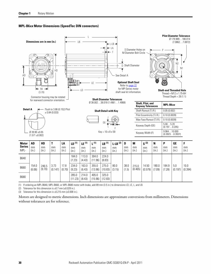
MPL-B6xx Motor Dimensions (SpeedTec DIN connectors)
Motors are designed to metric dimensions. Inch dimensions are approximate conversions from millimeters. Dimensions without tolerances are for reference.
MotorSeriesMPL-
AD mm(in.)
HDmm(in.)
Tmm(in.)
LAmm(in.)
LD (1)
mm (in.)
(1) If ordering an MPL-B640, MPL-B660, or MPL-B680 motor with brake, add 89 mm (3.5 in.) to dimensions LD, LE, L, and LB.
LE (1)
mm (in.)
L (1)
mm(in.)
LB (1)
mm(in.)
L-LB (2)
mm (in.)
(2) Tolerance for this dimension is ±0.7 mm (±0.028 in.).
Dmm(in.)
Mmm(in.)
S (3)
mm(in.)
(3) Tolerance for this dimension is ±0.215 mm (±0.008 in.).
Nmm(in.)
Pmm(in.)
GEmm(in.)
Fmm(in.)
B640
154.0(6.06)
246.5(9.70)
3.73(0.147)
17.8(0.70)
184.0(7.23)
113.0(4.43)
304.0(11.96)
224.0(8.83)
80.0(3.15)
38.0(1.5)
215.0(8.465)
14.50(0.579)
180.0(7.09)
184.9(7.28)
5.0(0.197)
10.0(0.394)
B660234.0(9.23)
163.0(6.43)
355.0(13.96)
275.0(10.83)
B680285.0(11.23)
214.0(8.43)
405.0(15.96)
325.0(12.83)
N1
P
94(3.70)
LA
LB
T
L-LB
AD
HD
D
L
LD
F
GE
LE
N2
Connector housing may be rotatedfor rearward connector orientation.
See Detail A
Pilot Diameter ToleranceØ 179.989…180.014
(7.0862…7.0872)
Ø 39.90 ±0.05 (1.571 ±0.002)
Key = 10 x 8 x 59
Flush to 3.86 (0.152) Pilot± 0.84 (0.033) Shaft Detail with KeyDetail A
Shaft Diameter TolerancesØ 38.002…38.018 (1.4961…1.4968)
S Diameter Holes onM Diameter Bolt Circle
Shaft, Pilot, and Keyway Tolerances MPL-B6xx
Shaft Runout (T.I.R.) 0.05 (0.002)
Pilot Eccentricity (T.I.R.) 0.10 (0.0039)
Max Face Runout (T.I.R.) 0.10 (0.0039)
Keyway Depth (GE) 5.00…5.20(0.197…0.205)
Keyway Width (F) 9.964…10.000(0.3923…0.3937)
Shaft Diameter
Optional Shaft SealRefer to page 22
for MP-Series motorshaft seal kit information.
Dimensions are in mm (in.)
Shaft-end Threaded HoleThread = M12 x 1.75-6HThread Depth = 28 (1.1)
Rockwell Automation Publication GMC-SG001Q-EN-P - April 2011 31
Rotary Motion Chapter 1
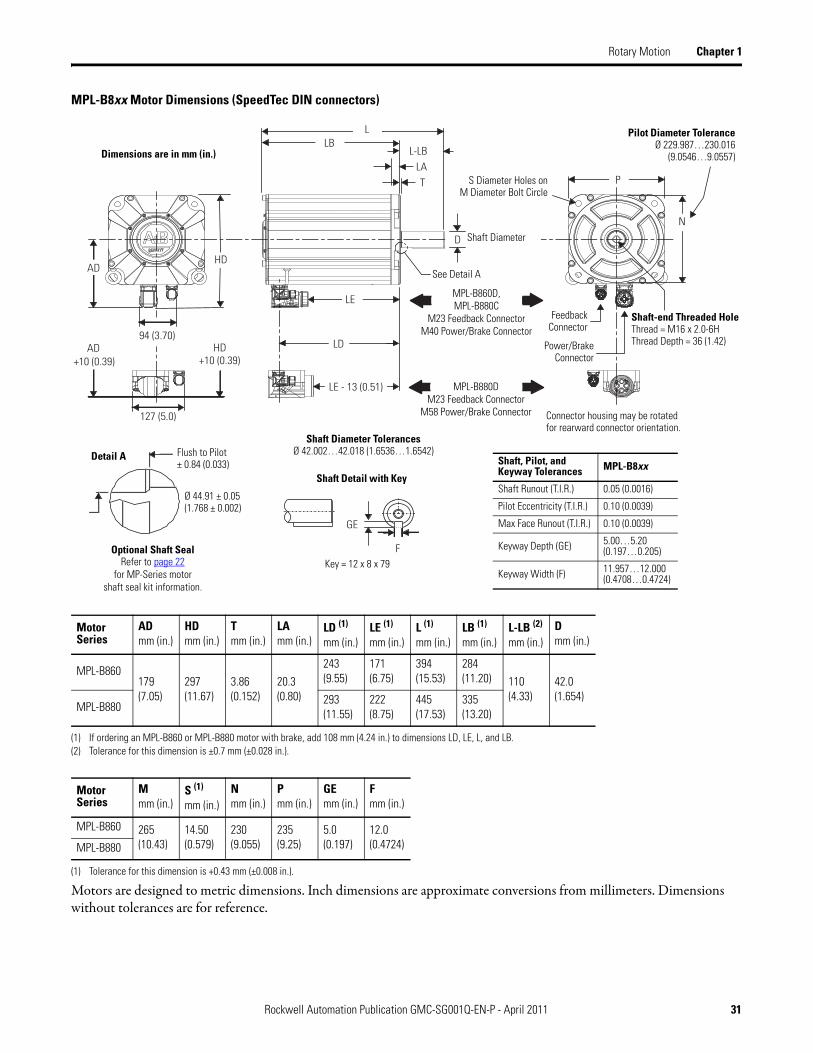
MPL-B8xx Motor Dimensions (SpeedTec DIN connectors)
Motors are designed to metric dimensions. Inch dimensions are approximate conversions from millimeters. Dimensions without tolerances are for reference.
MotorSeries
ADmm (in.)
HDmm (in.)
Tmm (in.)
LAmm (in.)
LD (1)
mm (in.)
(1) If ordering an MPL-B860 or MPL-B880 motor with brake, add 108 mm (4.24 in.) to dimensions LD, LE, L, and LB.
LE (1)
mm (in.)L (1)
mm (in.)LB (1)
mm (in.)L-LB (2)
mm (in.)
(2) Tolerance for this dimension is ±0.7 mm (±0.028 in.).
Dmm (in.)
MPL-B860179(7.05)
297 (11.67)
3.86 (0.152)
20.3 (0.80)
243(9.55)
171(6.75)
394(15.53)
284(11.20) 110
(4.33) 42.0(1.654)
MPL-B880293(11.55)
222(8.75)
445(17.53)
335(13.20)
MotorSeries
Mmm (in.)
S (1)
mm (in.)
(1) Tolerance for this dimension is +0.43 mm (±0.008 in.).
N mm (in.)
Pmm (in.)
GEmm (in.)
Fmm (in.)
MPL-B860 265(10.43)
14.50(0.579)
230(9.055)
235(9.25)
5.0(0.197)
12.0(0.4724) MPL-B880
N
PLA
LB
T
L-LB
ADHD
L
LD
GE
F
94 (3.70)
127 (5.0)
D
LE - 13 (0.51)
LE
AD HD+10 (0.39) +10 (0.39)
Shaft-end Threaded HoleThread = M16 x 2.0-6HThread Depth = 36 (1.42)
S Diameter Holes onM Diameter Bolt Circle
Pilot Diameter ToleranceØ 229.987…230.016
(9.0546…9.0557)
Ø 44.91 ± 0.05 (1.768 ± 0.002)
Flush to Pilot± 0.84 (0.033)
Detail A
See Detail A
Connector housing may be rotatedfor rearward connector orientation.
Shaft Diameter TolerancesØ 42.002…42.018 (1.6536…1.6542)
Key = 12 x 8 x 79
Shaft Detail with Key
Shaft Diameter
Optional Shaft SealRefer to page 22
for MP-Series motorshaft seal kit information.
Shaft, Pilot, and Keyway Tolerances MPL-B8xx
Shaft Runout (T.I.R.) 0.05 (0.0016)
Pilot Eccentricity (T.I.R.) 0.10 (0.0039)
Max Face Runout (T.I.R.) 0.10 (0.0039)
Keyway Depth (GE) 5.00…5.20(0.197…0.205)
Keyway Width (F) 11.957…12.000(0.4708…0.4724)
MPL-B860D,MPL-B880C
M23 Feedback Connector M40 Power/Brake Connector
MPL-B880DM23 Feedback Connector
M58 Power/Brake Connector
FeedbackConnector
Power/BrakeConnector
Dimensions are in mm (in.)
32 Rockwell Automation Publication GMC-SG001Q-EN-P - April 2011
Chapter 1 Rotary Motion
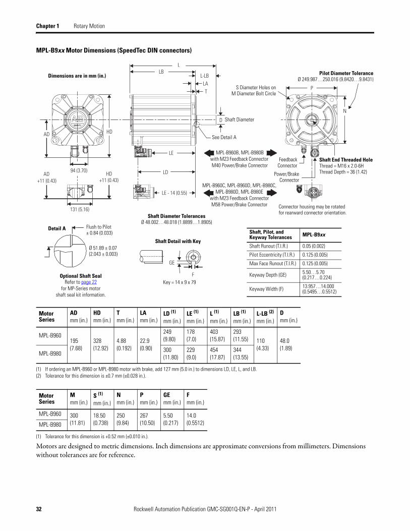
MPL-B9xx Motor Dimensions (SpeedTec DIN connectors)
Motors are designed to metric dimensions. Inch dimensions are approximate conversions from millimeters. Dimensions without tolerances are for reference.
MotorSeries
AD mm (in.)
HDmm (in.)
Tmm (in.)
LAmm (in.)
LD (1)
mm (in.)
(1) If ordering an MPL-B960 or MPL-B980 motor with brake, add 127 mm (5.0 in.) to dimensions LD, LE, L, and LB.
LE (1)
mm (in.)L (1)
mm (in.)LB (1)
mm (in.)L-LB (2)
mm (in.)
(2) Tolerance for this dimension is ±0.7 mm (±0.028 in.).
Dmm (in.)
MPL-B960195(7.68)
328 (12.92)
4.88 (0.192)
22.9 (0.90)
249(9.80)
178(7.0)
403(15.87)
293(11.55) 110
(4.33) 48.0(1.89)
MPL-B980300(11.80)
229(9.0)
454(17.87)
344(13.55)
MotorSeries
Mmm (in.)
S (1)
mm (in.)
(1) Tolerance for this dimension is +0.52 mm (±0.010 in.).
N mm (in.)
Pmm (in.)
GEmm (in.)
Fmm (in.)
MPL-B960 300(11.81)
18.50(0.738)
250(9.84)
267(10.50)
5.50(0.217)
14.0(0.5512) MPL-B980
N
PLA
LB
T
L-LB
AD
L
LD
GE
F
94 (3.70)
131 (5.16)
D
LE - 14 (0.55)
LE
HD
AD HD+11 (0.43) +11 (0.43)
S Diameter Holes onM Diameter Bolt Circle
Pilot Diameter ToleranceØ 249.987…250.016 (9.8420…9.8431)
Detail A
See Detail A
Connector housing may be rotatedfor rearward connector orientation.
Shaft Detail with Key
Shaft Diameter
Optional Shaft SealRefer to page 22
for MP-Series motorshaft seal kit information.
MPL-B960B, MPL-B980B with M23 Feedback Connector M40 Power/Brake Connector
MPL-B960C, MPL-B960D, MPL-B980C, MPL-B980D, MPL-B980E
with M23 Feedback Connector M58 Power/Brake Connector
FeedbackConnector
Power/BrakeConnector
Shaft End Threaded HoleThread = M16 x 2.0-6HThread Depth = 36 (1.42)
Ø 51.89 ± 0.07 (2.043 ± 0.003)
Flush to Pilot± 0.84 (0.033)
Key = 14 x 9 x 79
Shaft, Pilot, and Keyway Tolerances MPL-B9xx
Shaft Runout (T.I.R.) 0.05 (0.002)
Pilot Eccentricity (T.I.R.) 0.125 (0.005)
Max Face Runout (T.I.R.) 0.125 (0.005)
Keyway Depth (GE) 5.50…5.70(0.217…0.224)
Keyway Width (F) 13.957…14.000(0.5495…0.5512)
Shaft Diameter TolerancesØ 48.002…48.018 (1.8899…1.8905)
Dimensions are in mm (in.)
Rockwell Automation Publication GMC-SG001Q-EN-P - April 2011 33
Rotary Motion Chapter 1
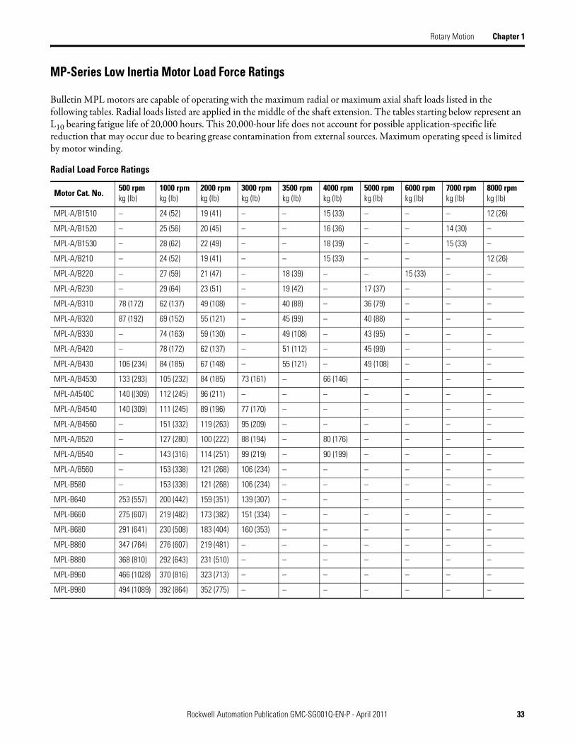
MP-Series Low Inertia Motor Load Force Ratings
Bulletin MPL motors are capable of operating with the maximum radial or maximum axial shaft loads listed in the following tables. Radial loads listed are applied in the middle of the shaft extension. The tables starting below represent an L10 bearing fatigue life of 20,000 hours. This 20,000-hour life does not account for possible application-specific life reduction that may occur due to bearing grease contamination from external sources. Maximum operating speed is limited by motor winding.
Radial Load Force Ratings
Motor Cat. No.500 rpmkg (lb)
1000 rpmkg (lb)
2000 rpmkg (lb)
3000 rpmkg (lb)
3500 rpmkg (lb)
4000 rpmkg (lb)
5000 rpmkg (lb)
6000 rpmkg (lb)
7000 rpmkg (lb)
8000 rpmkg (lb)
MPL-A/B1510 – 24 (52) 19 (41) – – 15 (33) – – – 12 (26)
MPL-A/B1520 – 25 (56) 20 (45) – – 16 (36) – – 14 (30) –
MPL-A/B1530 – 28 (62) 22 (49) – – 18 (39) – – 15 (33) –
MPL-A/B210 – 24 (52) 19 (41) – – 15 (33) – – – 12 (26)
MPL-A/B220 – 27 (59) 21 (47) – 18 (39) – – 15 (33) – –
MPL-A/B230 – 29 (64) 23 (51) – 19 (42) – 17 (37) – – –
MPL-A/B310 78 (172) 62 (137) 49 (108) – 40 (88) – 36 (79) – – –
MPL-A/B320 87 (192) 69 (152) 55 (121) – 45 (99) – 40 (88) – – –
MPL-A/B330 – 74 (163) 59 (130) – 49 (108) – 43 (95) – – –
MPL-A/B420 – 78 (172) 62 (137) – 51 (112) – 45 (99) – – –
MPL-A/B430 106 (234) 84 (185) 67 (148) – 55 (121) – 49 (108) – – –
MPL-A/B4530 133 (293) 105 (232) 84 (185) 73 (161) – 66 (146) – – – –
MPL-A4540C 140 ((309) 112 (245) 96 (211) – – – – – – –
MPL-A/B4540 140 (309) 111 (245) 89 (196) 77 (170) – – – – – –
MPL-A/B4560 – 151 (332) 119 (263) 95 (209) – – – – – –
MPL-A/B520 – 127 (280) 100 (222) 88 (194) – 80 (176) – – – –
MPL-A/B540 – 143 (316) 114 (251) 99 (219) – 90 (199) – – – –
MPL-A/B560 – 153 (338) 121 (268) 106 (234) – – – – – –
MPL-B580 – 153 (338) 121 (268) 106 (234) – – – – – –
MPL-B640 253 (557) 200 (442) 159 (351) 139 (307) – – – – – –
MPL-B660 275 (607) 219 (482) 173 (382) 151 (334) – – – – – –
MPL-B680 291 (641) 230 (508) 183 (404) 160 (353) – – – – – –
MPL-B860 347 (764) 276 (607) 219 (481) – – – – – – –
MPL-B880 368 (810) 292 (643) 231 (510) – – – – – – –
MPL-B960 466 (1028) 370 (816) 323 (713) – – – – – – –
MPL-B980 494 (1089) 392 (864) 352 (775) – – – – – – –
34 Rockwell Automation Publication GMC-SG001Q-EN-P - April 2011
Chapter 1 Rotary Motion
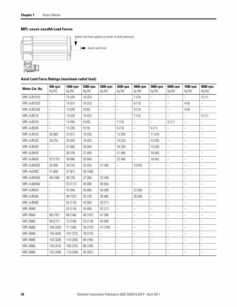
MPL-xxxxx-xxxxAA Load Forces
Axial Load Force Ratings (maximum radial load)
Motor Cat. No.500 rpmkg (lb)
1000 rpmkg (lb)
2000 rpmkg (lb)
3000 rpmkg (lb)
3500 rpmkg (lb)
4000 rpmkg (lb)
5000 rpmkg (lb)
6000 rpmkg (lb)
7000 rpmkg (lb)
8000 rpmkg (lb)
MPL-A/B1510 – 15 (33) 10 (22) – – 7 (15) – – – 5 (11)
MPL-A/B1520 – 14 (31) 10 (22) – – 6 (13) – – 4 (9) –
MPL-A/B1530 – 13 (29) 9 (20) – – 6 (13) – – 4 (8) –
MPL-A/B210 – 15 (33) 10 (22) – – 7 (15) – – – 5 (11)
MPL-A/B220 – 14 (30) 9 (20) – 7 (15) – – 5 (11) – –
MPL-A/B230 – 13 (28) 9 (19) – 6 (13) – 5 (11) – – –
MPL-A/B310 30 (66) 23 (51) 16 (35) – 13 (29) – 11 (24) – – –
MPL-A/B320 34 (75) 25 (55) 19 (42) – 15 (33) – 13 (29) – – –
MPL-A/B330 – 27 (60) 20 (44) – 16 (35) – 13 (29) – – –
MPL-A/B420 – 36 (79) 27 (60) – 21 (46) – 18 (40) – – –
MPL-A/B430 52 (115) 39 (86) 29 (64) – 22 (49) – 19 (42) – – –
MPL-A/B4530 45 (99) 34 (75) 25 (55) 21 (46) – 19 (42) – – – –
MPL-A4540C 31 (68) 37 (81) 49 (108) – – – – – – –
MPL-A/B4540 49 (108) 36 (79) 27 (60) 22 (49) – – – – – –
MPL-A/B4560 – 53 (117) 40 (88) 30 (65) – – – – – –
MPL-A/B520 – 42 (94) 30 (68) 26 (58) – 22 (50) – – – –
MPL-A/B540 – 48 (107) 35 (79) 30 (66) – 26 (58) – – – –
MPL-A/B560 – 52 (115) 43 (95) 32 (71) – – – – – –
MPL-B580 – 52 (115) 43 (95) 32 (71) – – – – – –
MPL-B640 89 (197) 66 (146) 48 (107) 41 (90) – – – – – –
MPL-B660 98 (217) 72 (159) 53 (118) 45 (99) – – – – – –
MPL-B680 104 (230) 77 (169) 34 (125) 47 (104) – – – – – –
MPL-B860 145 (320) 107 (237) 79 (175) – – – – – – –
MPL-B880 153 (338) 113 (250) 84 (185) – – – – – – –
MPL-B960 142 (314) 105 (232) 88 (194) – – – – – – –
MPL-B980 153 (338) 113 (249) 94 (207) – – – – – – –
Radial load force applied at center of shaft extension.
Axial Load Force

Rockwell Automation Publication GMC-SG001Q-EN-P - April 2011 35
Rotary Motion Chapter 1
Axial Load Force Ratings (zero radial load)
Motor Cat. No.500 rpmkg (lb)
1000 rpmkg (lb)
2000 rpmkg (lb)
3000 rpmkg (lb)
3500 rpmkg (lb)
4000 rpmkg (lb)
5000 rpmkg (lb)
6000 rpmkg (lb)
7000 rpmkg (lb)
8000 rpmkg (lb)
MPL-A/B1510 – 24 (53) 17 (37) – – 12 (26) – – – 8 (18)
MPL-A/B1520 – 24 (53) 17 (37) – – 12 (26) – – 9 (19) –
MPL-A/B1530 – 24 (53) 17 (37) – – 12 (26) – – 9 (19) –
MPL-A/B210 – 24 (53) 17 (37) – – 12 (26) – – – 8 (18)
MPL-A/B220 – 24 (53) 17 (37) – 13 (28) – – 10 (22) – –
MPL-A/B230 – 24 (53) 17 (37) – 13 (28) – 10 (22) – – –
MPL-A/B310 49 (108) 36 (79) 27 (60) – 21 (46) – 18 (40) – – –
MPL-A/B320 49 (108) 36 (79) 27 (60) – 21 (46) – 18 (40) – – –
MPL-A/B330 – 36 (79) 27 (60) – 21 (46) – 18 (40) – – –
MPL-A/B420 – 51 (112) 38 (84) – 30 (66) – 25 (55) – – –
MPL-A/B430 69 (152) 51 (112) 38 (84) – 30 (66) – 25 (55) – – –
MPL-A/B4530 69 (152) 51 (112) 38 (84) 31 (68) – 28 (62) – – – –
MPL-A4540C 68 (150) 51 (112) 43 (95) – – – – – – –
MPL-A/B4540 69 (152) 51 (112) 38 (84) 31 (68) – – – – – –
MPL-A/B4560 – 69 (152) 51 (112) 38 (84) – – – – – –
MPL-A/B520 – 67 (149) 49 (109) 41 (92) – 36 (81) – – – –
MPL-A/B540 – 67 (149) 49 (109) 41 (92) – 36 (81) – – – –
MPL-A/B560 – 67 (149) 49 (109) 41 (92) – – – – – –
MPL-B580 – 67 (149) 49 (109) 41 (92) – – – – – –
MPL-B640 136 (300) 99 (219) 74 (163) 62 (137) – – – – – –
MPL-B660 136 (300) 99 (219) 74 (163) 62 (137) – – – – – –
MPL-B680 136 (300) 99 (219) 74 (163) 62 (137) – – – – – –
MPL-B860 201 (443) 147 (323) 110 (242) – – – – – – –
MPL-B880 201 (443) 147 (323) 110 (242) – – – – – – –
MPL-B960 215 (473) 159 (350) 133 (293) – – – – – – –
MPL-B980 215 (473) 159 (350) 133 (293) – – – – – – –
36 Rockwell Automation Publication GMC-SG001Q-EN-P - April 2011
Chapter 1 Rotary Motion
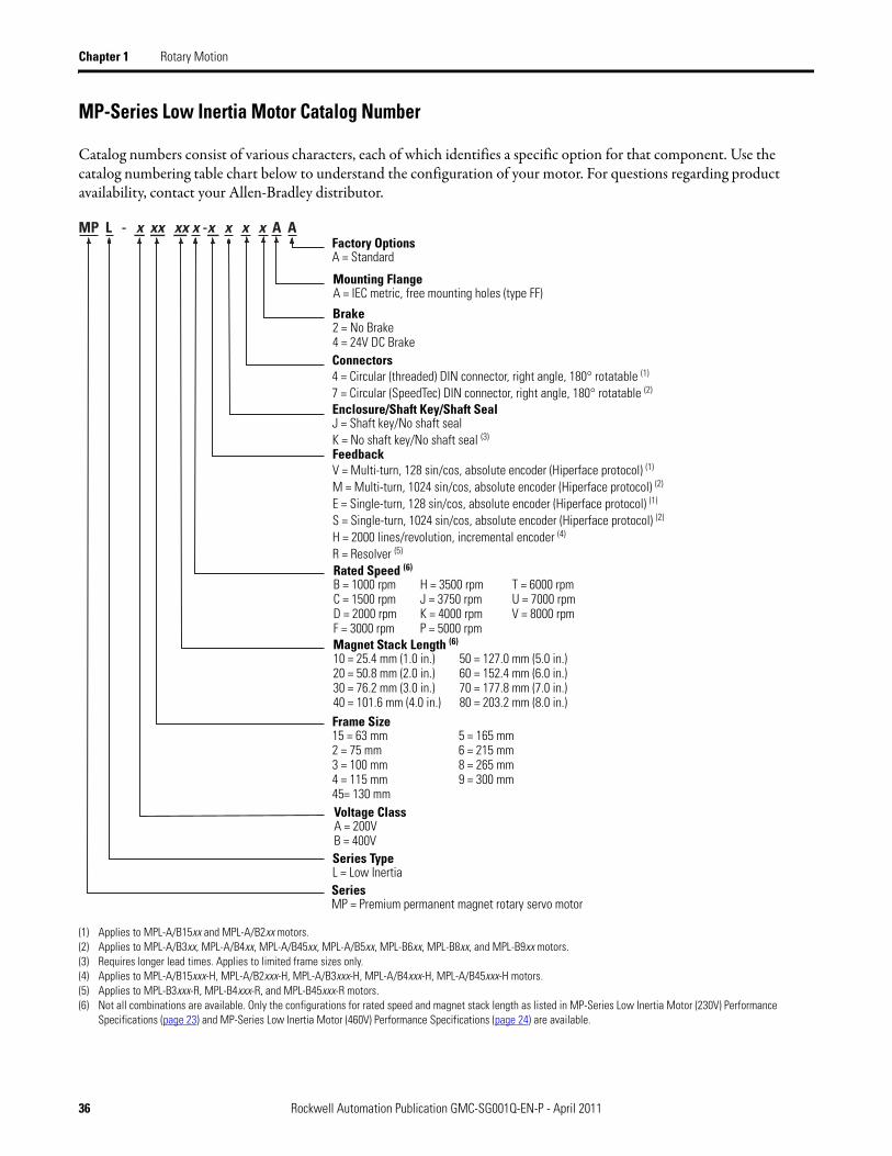
MP-Series Low Inertia Motor Catalog Number
Catalog numbers consist of various characters, each of which identifies a specific option for that component. Use the catalog numbering table chart below to understand the configuration of your motor. For questions regarding product availability, contact your Allen-Bradley distributor.
(1) Applies to MPL-A/B15xx and MPL-A/B2xx motors.(2) Applies to MPL-A/B3xx, MPL-A/B4xx, MPL-A/B45xx, MPL-A/B5xx, MPL-B6xx, MPL-B8xx, and MPL-B9xx motors.(3) Requires longer lead times. Applies to limited frame sizes only.(4) Applies to MPL-A/B15xxx-H, MPL-A/B2xxx-H, MPL-A/B3xxx-H, MPL-A/B4xxx-H, MPL-A/B45xxx-H motors.(5) Applies to MPL-B3xxx-R, MPL-B4xxx-R, and MPL-B45xxx-R motors.(6) Not all combinations are available. Only the configurations for rated speed and magnet stack length as listed in MP-Series Low Inertia Motor (230V) Performance
Specifications (page 23) and MP-Series Low Inertia Motor (460V) Performance Specifications (page 24) are available.
MP L - x xx xx x -x x x x A AFactory OptionsA = Standard
Mounting FlangeA = IEC metric, free mounting holes (type FF)
Brake2 = No Brake4 = 24V DC Brake
Enclosure/Shaft Key/Shaft SealJ = Shaft key/No shaft sealK = No shaft key/No shaft seal (3)
Connectors4 = Circular (threaded) DIN connector, right angle, 180° rotatable (1)
7 = Circular (SpeedTec) DIN connector, right angle, 180° rotatable (2)
FeedbackV = Multi-turn, 128 sin/cos, absolute encoder (Hiperface protocol) (1)
M = Multi-turn, 1024 sin/cos, absolute encoder (Hiperface protocol) (2)
E = Single-turn, 128 sin/cos, absolute encoder (Hiperface protocol) (1)
S = Single-turn, 1024 sin/cos, absolute encoder (Hiperface protocol) (2)
H = 2000 lines/revolution, incremental encoder (4)
R = Resolver (5)
Rated Speed (6)
B = 1000 rpm H = 3500 rpm T = 6000 rpmC = 1500 rpm J = 3750 rpm U = 7000 rpmD = 2000 rpm K = 4000 rpm V = 8000 rpmF = 3000 rpm P = 5000 rpmMagnet Stack Length (6)
10 = 25.4 mm (1.0 in.) 50 = 127.0 mm (5.0 in.)20 = 50.8 mm (2.0 in.) 60 = 152.4 mm (6.0 in.)30 = 76.2 mm (3.0 in.) 70 = 177.8 mm (7.0 in.)40 = 101.6 mm (4.0 in.) 80 = 203.2 mm (8.0 in.)Frame Size15 = 63 mm 5 = 165 mm2 = 75 mm 6 = 215 mm3 = 100 mm 8 = 265 mm4 = 115 mm 9 = 300 mm45= 130 mmVoltage ClassA = 200V B = 400V Series TypeL = Low InertiaSeriesMP = Premium permanent magnet rotary servo motor