Moving an asteroid with electric solar wind · PDF fileMoving an asteroid with electric solar...
8
Astrophys. Space Sci. Trans., 6, 41–48, 2010 www.astrophys-space-sci-trans.net/6/41/2010/ doi:10.5194/astra-6-41-2010 © Author(s) 2010. CC Attribution 3.0 License. Astrophysics and Space Sciences Transactions Moving an asteroid with electric solar wind sail S. Merikallio and P. Janhunen Finnish Meteorological Institute, Po. Box. 503, FIN-00101, Helsinki, Finland Received: 12 March 2010 – Revised: 1 November 2010 – Accepted: 2 November 2010 – Published: 7 December 2010 Abstract. The electric solar wind sail (E-Sail) is a new propulsion method for interplanetary travel which was in- vented in 2006 and is currently under development. The E-Sail uses charged tethers to extract momentum from the solar wind particles to obtain propulsive thrust. According to current estimates, the E-Sail is 2-3 orders of magnitude bet- ter than traditional propulsion methods (chemical rockets and ion engines) in terms of produced lifetime-integrated impulse per propulsion system mass. Here we analyze the problem of using the E-Sail for directly deflecting an Earth-threatening asteroid. The problem then culminates into how to attach the E-Sail device to the asteroid. We assess alternative attach- ment strategies, namely straightforward direct towing with a cable and the gravity tractor method which works for a wider variety of situations. We also consider possible tech- niques to scale up the E-Sail force beyond the baseline one Newton level to deal with more imminent or larger asteroid or cometary threats. As a baseline case we consider an as- teroid of effective diameter of 140 m and mass of 3 million tons, which can be deflected with a baseline 1 N E-Sail within 10 years. With a 5 N E-Sail the deflection could be achieved in 5 years. Once developed, the E-Sail would appear to pro- vide a safe and reasonably low-cost way of deflecting dan- gerous asteroids and other heavenly bodies in cases where the collision threat becomes known several years in advance. 1 Introduction The electric solar wind sail, from here on referred to as E- Sail, is a new method for producing propulsion in space (Janhunen, 2010; Janhunen, 2004; Janhunen and Sandroos, 2007). Contrary to the more traditional solar sail that utilises Correspondence to: S. Merikallio ([email protected]) solar photon pressure, the E-Sail extracts momentum from charged solar wind particles (Janhunen, 2004; Janhunen and Sandroos, 2007). A number of positively charged tethers are radially deployed from a rotating spacecraft and stretched by the centrifugal force. Because the tethers are charged, they deflect charged particles of the streaming solar wind (from here also referrred to as SW), thus producing a Coulomb drag interaction which transfers momentum from the particles to the tethers. Most of the momentum comes from the pro- tons, where the majority of the solar wind momentum flux is. Solar wind electrons will continuously impact the pos- itively charged tethers, making it necessary to maintain the tether charging by actively pumping out electrons from the system. The onboard electron gun, typically of few hundred watts of power, is used to keep the spacecraft and the wires in a high (typically 20 kV) positive potential. Figure 1 illustrates the E-Sail concept. The modest amount of electric power required to operate the electron gun is typ- ically created by solar panels. The sail rotates so that the centrifugal force keeps the wires stretched and prevents them from colliding with each other. By varying the relative charg- ing of the individual tethers, the direction of the total force can be altered and the spacecraft thus steered (Janhunen and Sandroos, 2007). Although this inevitably causes some fluc- tuations within the tethers, the mutual repulsive forces be- tween them and the centrifugal force keep the sail roughly in shape. This ability to adjust both the direction and the amount of the force independently of each other gives the E-Sail superior steering possibilities when compared to the traditional solar sail, for which the force vector direction and magnitude change in unison. Like a conventional solar sail, an E-Sail spacecraft can also work its way towards the Sun by inclining the sail so that the resulting force has a compo- nent which tends to brake the spacecraft in its orbital motion around the Sun and thereby lose angular momentum and de- scend deeper into the solar gravity well. Published by Copernicus Publications on behalf of the Arbeitsgemeinschaft Extraterrestrische Forschung e.V.
Transcript of Moving an asteroid with electric solar wind · PDF fileMoving an asteroid with electric solar...
Astrophys. Space Sci. Trans., 6, 41–48, 2010www.astrophys-space-sci-trans.net/6/41/2010/doi:10.5194/astra-6-41-2010© Author(s) 2010. CC Attribution 3.0 License. Astrophysics andSpace Sciences
Tr ansactions
Moving an asteroid with electric solar wind sail
S. Merikallio and P. Janhunen
Finnish Meteorological Institute, Po. Box. 503, FIN-00101, Helsinki, Finland
Received: 12 March 2010 – Revised: 1 November 2010 – Accepted: 2 November 2010 – Published: 7 December 2010
Abstract. The electric solar wind sail (E-Sail) is a newpropulsion method for interplanetary travel which was in-vented in 2006 and is currently under development. TheE-Sail uses charged tethers to extract momentum from thesolar wind particles to obtain propulsive thrust. According tocurrent estimates, the E-Sail is 2-3 orders of magnitude bet-ter than traditional propulsion methods (chemical rockets andion engines) in terms of produced lifetime-integrated impulseper propulsion system mass. Here we analyze the problem ofusing the E-Sail for directly deflecting an Earth-threateningasteroid. The problem then culminates into how to attach theE-Sail device to the asteroid. We assess alternative attach-ment strategies, namely straightforward direct towing witha cable and the gravity tractor method which works for awider variety of situations. We also consider possible tech-niques to scale up the E-Sail force beyond the baseline oneNewton level to deal with more imminent or larger asteroidor cometary threats. As a baseline case we consider an as-teroid of effective diameter of 140 m and mass of 3 milliontons, which can be deflected with a baseline 1 N E-Sail within10 years. With a 5 N E-Sail the deflection could be achievedin 5 years. Once developed, the E-Sail would appear to pro-vide a safe and reasonably low-cost way of deflecting dan-gerous asteroids and other heavenly bodies in cases wherethe collision threat becomes known several years in advance.
1 Introduction
The electric solar wind sail, from here on referred to as E-Sail, is a new method for producing propulsion in space(Janhunen, 2010; Janhunen, 2004; Janhunen and Sandroos,2007). Contrary to the more traditional solar sail that utilises
Correspondence to:S. Merikallio([email protected])
solar photon pressure, the E-Sail extracts momentum fromcharged solar wind particles (Janhunen, 2004; Janhunen andSandroos, 2007). A number of positively charged tethers areradially deployed from a rotating spacecraft and stretched bythe centrifugal force. Because the tethers are charged, theydeflect charged particles of the streaming solar wind (fromhere also referrred to as SW), thus producing a Coulomb draginteraction which transfers momentum from the particles tothe tethers. Most of the momentum comes from the pro-tons, where the majority of the solar wind momentum fluxis. Solar wind electrons will continuously impact the pos-itively charged tethers, making it necessary to maintain thetether charging by actively pumping out electrons from thesystem. The onboard electron gun, typically of few hundredwatts of power, is used to keep the spacecraft and the wiresin a high (typically 20 kV) positive potential.
Figure 1 illustrates the E-Sail concept. The modest amountof electric power required to operate the electron gun is typ-ically created by solar panels. The sail rotates so that thecentrifugal force keeps the wires stretched and prevents themfrom colliding with each other. By varying the relative charg-ing of the individual tethers, the direction of the total forcecan be altered and the spacecraft thus steered (Janhunen andSandroos, 2007). Although this inevitably causes some fluc-tuations within the tethers, the mutual repulsive forces be-tween them and the centrifugal force keep the sail roughlyin shape. This ability to adjust both the direction and theamount of the force independently of each other gives theE-Sail superior steering possibilities when compared to thetraditional solar sail, for which the force vector direction andmagnitude change in unison. Like a conventional solar sail,an E-Sail spacecraft can also work its way towards the Sunby inclining the sail so that the resulting force has a compo-nent which tends to brake the spacecraft in its orbital motionaround the Sun and thereby lose angular momentum and de-scend deeper into the solar gravity well.
Published by Copernicus Publications on behalf of the Arbeitsgemeinschaft Extraterrestrische Forschung e.V.
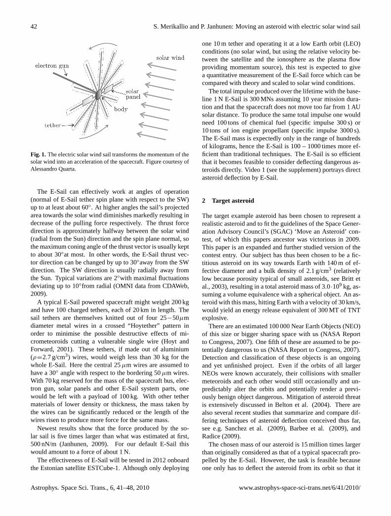
42 S. Merikallio and P. Janhunen: Moving an asteroid with electric solar wind sail
Fig. 1. The electric solar wind sail transforms the momentum of thesolar wind into an acceleration of the spacecraft. Figure courtesy ofAlessandro Quarta.
The E-Sail can effectively work at angles of operation(normal of E-Sail tether spin plane with respect to the SW)up to at least about 60◦. At higher angles the sail’s projectedarea towards the solar wind diminishes markedly resulting indecrease of the pulling force respectively. The thrust forcedirection is approximately halfway between the solar wind(radial from the Sun) direction and the spin plane normal, sothe maximum coning angle of the thrust vector is usually keptto about 30◦at most. In other words, the E-Sail thrust vec-tor direction can be changed by up to 30◦away from the SWdirection. The SW direction is usually radially away fromthe Sun. Typical variations are 2◦with maximal fluctuationsdeviating up to 10◦from radial (OMNI data from CDAWeb,2009).
A typical E-Sail powered spacecraft might weight 200 kgand have 100 charged tethers, each of 20 km in length. Thesail tethers are themselves knitted out of four 25−50µmdiameter metal wires in a crossed “Hoytether” pattern inorder to minimise the possible destructive effects of mi-crometeoroids cutting a vulnerable single wire (Hoyt andForward, 2001). These tethers, if made out of aluminium(ρ=2.7 g/cm3) wires, would weigh less than 30 kg for thewhole E-Sail. Here the central 25µm wires are assumed tohave a 30◦ angle with respect to the bordering 50µm wires.With 70 kg reserved for the mass of the spacecraft bus, elec-tron gun, solar panels and other E-Sail system parts, onewould be left with a payload of 100 kg. With other tethermaterials of lower density or thickness, the mass taken bythe wires can be significantly reduced or the length of thewires risen to produce more force for the same mass.
Newest results show that the force produced by the so-lar sail is five times larger than what was estimated at first,500 nN/m (Janhunen, 2009). For our default E-Sail thiswould amount to a force of about 1 N.
The effectiveness of E-Sail will be tested in 2012 onboardthe Estonian satellite ESTCube-1. Although only deploying
one 10 m tether and operating it at a low Earth orbit (LEO)conditions (no solar wind, but using the relative velocity be-tween the satellite and the ionosphere as the plasma flowproviding momentum source), this test is expected to givea quantitative measurement of the E-Sail force which can becompared with theory and scaled to solar wind conditions.
The total impulse produced over the lifetime with the base-line 1 N E-Sail is 300 MNs assuming 10 year mission dura-tion and that the spacecraft does not move too far from 1 AUsolar distance. To produce the same total impulse one wouldneed 100 tons of chemical fuel (specific impulse 300 s) or10 tons of ion engine propellant (specific impulse 3000 s).The E-Sail mass is expectedly only in the range of hundredsof kilograms, hence the E-Sail is 100 – 1000 times more ef-ficient than traditional techniques. The E-Sail is so efficientthat it becomes feasible to consider deflecting dangerous as-teroids directly. Video 1 (see the supplement) portrays directasteroid deflection by E-Sail.
2 Target asteroid
The target example asteroid has been chosen to represent arealistic asteroid and to fit the guidelines of the Space Gener-ation Advisory Council’s (SGAC) ‘Move an Asteroid’ con-test, of which this papers ancestor was victorious in 2009.This paper is an expanded and further studied version of thecontest entry. Our subject has thus been chosen to be a fic-titious asteroid on its way towards Earth with 140 m of ef-fective diameter and a bulk density of 2.1 g/cm3 (relativelylow because porosity typical of small asteroids, see Britt etal., 2003), resulting in a total asteroid mass of 3.0·109 kg, as-suming a volume equivalence with a spherical object. An as-teroid with this mass, hitting Earth with a velocity of 30 km/s,would yield an energy release equivalent of 300 MT of TNTexplosive.
There are an estimated 100 000 Near Earth Objects (NEO)of this size or bigger sharing space with us (NASA Reportto Congress, 2007). One fifth of these are assumed to be po-tentially dangerous to us (NASA Report to Congress, 2007).Detection and classification of these objects is an ongoingand yet unfinished project. Even if the orbits of all largerNEOs were known accurately, their collisions with smallermeteoroids and each other would still occasionally and un-predictably alter the orbits and potentially render a previ-ously benign object dangerous. Mitigation of asteroid threatis extensively discussed in Belton et al. (2004). There arealso several recent studies that summarize and compare dif-fering techniques of asteroid deflection conceived thus far,see e.g. Sanchez et al. (2009), Barbee et al. (2009), andRadice (2009).
The chosen mass of our asteroid is 15 million times largerthan originally considered as that of a typical spacecraft pro-pelled by the E-Sail. However, the task is feasible becauseone only has to deflect the asteroid from its orbit so that it
Astrophys. Space Sci. Trans., 6, 41–48, 2010 www.astrophys-space-sci-trans.net/6/41/2010/
S. Merikallio and P. Janhunen: Moving an asteroid with electric solar wind sail 43
will not hit the Earth, in contrast to taking a tiny spacecraftall the way around the solar system.
3 Avoiding the Earth
To avoid the impact with the Earth, one has to change theasteroid’s orbit. Let us consider the asteroid that is being ac-celerated or decelerated along its track by aligning the forcevector produced by the E-Sail with the velocity vector of theasteroid. The E-Sail either follows (brakes) or leads (accel-erates) the asteroid on its track. Let us take the maximumusable operational angle to be 60◦with respect to the SW(meaning that towing, e.g., coning angle is 30◦). Pure brak-ing or pure orbit-aligned acceleration is not possible for cir-cular orbits. On a circular orbit the maximum angle betweenthe Sun direction and the towing force can momentarily reach40◦during some 10◦SW-fluctuation. Periods of higher im-pact angles can last several days and by manoeuvring theE-Sail to take advantage of these, a careful E-Sail operatormight gain some extra orbit-aligned acceleration. For sim-plicity, however, we shall ignore this possibility and assumea steady solar wind coming directly from the Sun, thus lim-iting the steering angle to 30◦and below from the radial.
To model the asteroid motion, we have used the so calledleapfrog method, in which the time is divided into discretesteps on which the location and the velocity of the asteroidare calculated in turns on every other step (Hut and Makino,2009). For simplicity, relativistic effects have been neglectedas are all gravitational anomalies. The modeling was per-formed on Matlab with a time step of 100 s. For the targetasteoids orbit we have chosen one with perihelion slightlybelow that of the Earth’s track (1.0 AU) and aphelion of1.23 AU. As the E-Sail is most powerful closer to the Sun,it should be stressed that there is a large population of aster-oids with near Earth orbits for which the E-Sail should workbetter than in our example.
For our models, we have considered the operation anglesθ
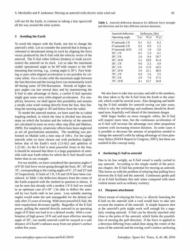
of 0◦(E-Sail force vector going through the Sun), 30◦, 50◦and70◦, corresponding to the coning angles of 0◦, 15◦and 25◦and35◦respectively. E-Sails of 1 N, 5 N and 10 N have been con-sidered. In Table 1 the deflection distance from the center ofthe Earth acquired with the method in question is shown. Itcan be seen that already with a modest 1 N E-Sail we wouldin an optimum case (θ=50◦ ) be able to deflect the aster-oid by two Earth radii in ten years. Less suitable steeringangles would make the task manageable for the default sailonly after 15 years of towing. With more powerful E-Sail, thetime requirement decreases rapidly. Regardles of the E-Sailpower, pulling the asteroid directly outward in an operatingangle of 0◦does not lead in to a desired results. With a com-bination of high power 10 N sail and most effective steeringangle of 50◦, our model asteroid could be swayed at a safedistance of 6 Earth’s radiuses away from our planet’s surfacewithin five years.
Table 1. Asteroid deflection distances for different force strengthand directions and for thee different mission durations.
Asteroid deflection Deflection, [Re]Operating angle 5 yr 10 yr 15 yr
0◦outwards 1 N 0.1 0.2 0.30◦outwards 5 N 0.5 0.9 1.50◦outwards 10 N 1.0 1.8 3.030◦, 1 N 0.5 1.9 4.130◦, 5 N 2.6 9.4 20.730◦, 10 N 5.2 18.9 41.450◦, 1 N 0.6 2.2 4.950◦, 5 N 3.0 11.0 24.550◦, 10 N 5.9 22.1 48.970◦, 1 N 0.4 1.6 3.570◦, 5 N 2.0 7.9 17.570◦, 10 N 4.1 15.7 34.9
We also have to take into account, and add to the numbers,the time taken to fly the E-Sail from the Earth to the aster-oid, which could be several years. Also designing and build-ing the E-Sail suitable for asteroid towing can take years,which is why the technology and readiness should be devel-oped now, hopefully well ahead of the imminent danger.
With larger bodies on more energetic orbits, the E-Sailwill require more time, but the continuous acceleration ofan E-Sail will increase the advantage over other propulsionsystems with increasing mission duration. In some cases itis possible to decrease the amount of propulsion needed tochange the asteroid’s orbit by taking advantage of close plan-etary flybys (NASA Report to Congress, 2007), but these areomitted in this concept study.
4 Anchoring E-Sail to asteroid
Due to its low weight, an E-Sail vessel is easily carried toany asteroid. According to the simple model of the previ-ous chapter, the E-Sail has potential for moving an asteroid.This leaves us with the problem of relaying that pulling forcebetween the E-Sail and the asteroid. Continuous gentle pullof an E-Sail facilitates this task when compared with moreviolent means such as ordinary rocketry.
4.1 Harpoon attachment
Direct means of relaying the force, i.e. directly fastening theE-Sail on the asteroid with a cord would have to take intoaccount the rotation of the asteroid. A simple harpoon shotat the asteroid’s pole might work well enough for a regu-larly rotating asteroid. E-Sail can be directly attached onlyclose to the poles of the asteroid, which limits the possibil-ities of steering the pull direction. If the force is applied ina direction differing from radial (line along the centre of themass of the asteroid and the towing cord’s surface anchoring
www.astrophys-space-sci-trans.net/6/41/2010/ Astrophys. Space Sci. Trans., 6, 41–48, 2010
44 S. Merikallio and P. Janhunen: Moving an asteroid with electric solar wind sail
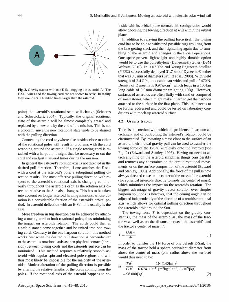
Fig. 2. Gravity tractor with one E-Sail tugging the asteroid ‘A’. TheE-Sail wires and the towing cord are not shown to scale. In realitythey would scale hundred times larger than the asteroid.
point) the asteroid’s rotational state will change (Scheeresand Schweickart, 2004). Typically, the original rotationalstate of the asteroid will be almost completely erased andreplaced by a new one by the end of the mission. This is nota problem, since the new rotational state tends to be alignedwith the pulling direction.
Connecting the cord anywhere else besides close to eitherof the rotational poles will result in problems with the cordwrapping around the asteroid. If a single towing cord is at-tached with a harpoon, it might thus be necessary to cut thecord and readjust it several times during the mission.
In general the asteroid’s rotation axis is not directed in thedesired pull direction. Therefore, if one attaches the E-sailwith a cord at the asteroid’s pole, a suboptimal pulling di-rection results. The most effective pulling direction with re-spect to the asteroid’s rotational axis is changing continu-ously throughout the asteroid’s orbit as the rotation axis di-rection relative to the Sun also changes. This has to be takeninto account on longer asteroid hauling missions, whose du-ration is a considerable fraction of the asteroid’s orbital pe-riod. In asteroid deflection with an E-Sail this usually is thecase.
More freedom in tug direction can be achieved by attach-ing a towing cord to both rotational poles, thus minimizingthe impact on asteroids rotation. The cords could then ata safe distance come together and be united into one tow-ing cord. Contrary to the one harpoon solution, this methodworks best when the desired pull direction is perpendicularto the asteroids rotational axis as then physical contact (abra-sion) between towing cords and the asteroids surface can beminimized. This method requires a relatively smooth as-teroid with regular spin and elevated pole regions and willthus most likely be impossible for the majority of the aster-oids. Modest alteration of the pulling direction is possibleby altering the relative lengths of the cords coming from thepoles. If the rotational axis of the asteroid happens to co-
inside with its orbital plane normal, this configuration wouldallow choosing the towing direction at will within the orbitalplane.
In addition to relaying the pulling force itself, the towingcord has to be able to withstand possible tugs resulting fromthe line getting slack and then tightening again due to tum-bling of the asteroid and changes in the E-Sail operations.One space-proven, lightweight and highly durable optionwould be to use the polyethylene (Dyneema®) tether (DSMWebsite, 2010). In 2007 The 2nd Young Engineers Satellite(YES2) successfully deployed 31.7 km of Dyneema® tetherthat was 0.5 mm of diameter (Kruijff et al., 2008). With yieldstrength of 2.4 GPa, this cable can withstand pull of 470 N.Density of Dyneema is 0.97 g/cm3, which leads in a 100 kmlong cable of 0.5 mm diameter weighting 19 kg. However,surfaces of asteroids are often fluffy with sand or composedof small stones, which might make it hard to get the harpoonattached to the surface in the first place. This issue needs tobe further addressed and could be tested on laboratory con-ditions with mock-up asteroid surface.
4.2 Gravity tractor
There is one method with which the problems of harpoon at-tachment and of controlling the asteroid’s rotation could becircumvented. By levitating a mass close to the surface of anasteroid, their mutual gravity pull can be used to transfer thetowing force of the E-Sail wirelessly onto the asteroid (seeFig. 2) (Edward and Stanley, 1995). Having no need to at-tach anything on the asteroid simplifies things considerablyand removes any constraints on the erratic rotational move-ments, or on the surface composition of the asteroid (Edwardand Stanley, 1995). Additionally, the force of the pull is nowalways directed close to the center of the mass of the asteroid(for spherical asteroids directly towards the center of mass),which minimizes the impact on the asteroids rotation. Thebiggest advantage of gravity tractor solution over simplerharpoon solutions is however, that the coning angle can beadjusted independently of the direction of asteroids rotationalaxis, which allows for optimal pulling direction throughoutthe asteroids orbit around the Sun.
The towing forceT is dependent on the gravity con-stantG, the mass of the asteroidM, the mass of the trac-tor m as well as on the distance between the asteroid’s andthe tractor’s center of mass,d:
T =GMm
d2(1)
In order to transfer the 1 N force of one default E-Sail, themass of the tractor held a sphere equivalent diameter fromabove the center of mass (one radius above the surface)would thus need to be:
m =T d2
GM=
1N (140[m])2
6.674·10−11[m3kg−1s−2] 3·109[kg]
= 98 000[kg] (2)
Astrophys. Space Sci. Trans., 6, 41–48, 2010 www.astrophys-space-sci-trans.net/6/41/2010/
S. Merikallio and P. Janhunen: Moving an asteroid with electric solar wind sail 45
For a nonspherical steadily rotating asteroid it might be pos-sible to take the tractor even closer, but on the other hand anerratic circulation and safety considerations probably forceus to keep a higher distance. For a safe limit of one diameteraway from the surface (210 m from the center of mass), therequired tractor mass would rise up to 220 000 kg, for twodiameters above surface up to 400 000 kg, and so on risingin the square of the distance. For an advanced E-Sail pullingwith 10 N instead of 1 N, these masses would rise tenfoldbut on the other hand for larger asteroids the tractor mass re-quirement would decrease. In order to avoid any risk of theE-Sail tethers getting into unwanted contact with the surfaceof the asteroid, the station would be best to position itself far-ther away from the asteroid, only connected with a lengthytowing cord to the gravity tractor mass.
The mass of the Rosetta spacecraft, currently flying to-wards comet 67P/Churyumov-Gerasimenko, will be about1400 kg when it reaches its target asteroid (ESA Rosettawebsite). Our gravity tractor’s mass demand to tow ourmodel asteroid with one Newton force could thus be satis-fied with seventy Rosetta sized spacecraft. With new heavylaunchers, like Ares V being currently developed by NASA,the tractor mass could be delivered with only a few launches.Ares V will be capable of delivering over 50 tons of mass intoescape track from Earth (Stahl et al. 2009).
Surely, in an hour of need, transporting this mass from theEarth to the asteroid would not be a major resource issue,but there might be a yet cheaper way: If one can land con-trollably to the asteroid, also using the mass of the asteroiditself to fill the tractor’s containers might be plausible. Somepart of the asteroid could be mined by exploding or diggingand then collected into nets or bags that would be connectedto the tow of the electric sail. This would erase the trou-ble of flying the passive tractor mass from Earth to the as-teroid. The overall mission might thus be expedited and thecost lessened. Instead of hauling the whole tractor mass fromthe Earth into the vicinity of the asteroid, we would now onlyneed the rubble bags, some collection method of the rubbleand the towing cord for towing the tractor.
Should the mass of the tractor be slightly smaller or largerthan planned, the situation could easily be rectified by hold-ing the tractor correspondingly closer or farther away fromthe asteroid.
On some asteroids containing enough loose rocks onemight get enough mass simply by carrying these rocks intocontainers (bags or nets). These containers would then belevitated from the surface of the asteroid by small chemicalpropulsion rockets, after which they can be attached to the E-Sail vessel using a similar harpooning procedure as proposedin the previous sub-section. Simple robots could be placed onthe surface to haul loose rocks and rubble in to waiting netsor containers. This method wouldn’t produce as much a riskof loose rubble flying around, but would require developmentof complex robots working with artificial intelligence in ad-dition to taking more time to fulfil their mission. This style of
controlled mass gathering might easily increase the missionduration by an half a year or more. If there wouldn’t existenough loose rubble, minor explosions or drilling machinescould be used to loosen it from the asteroid.
In all of these methods the energy for surface operationsmight come from the Sun. In that case the inevitable raisingof dust from the surface of the asteroid may produce prob-lems in blocking the solar panels and some cleansing systemmight be necessary. Also the rotation of the asteroid wouldperiodically bring the surface robots into shadow, slowingdown their work. Nuclear or fuel cell energy could go aroundthis problem but would require more mass to be transferredfrom the Earth.
Biggest foreseen problem with the gravity tractor methodis the controlling of the system. Two masses pulling eachother with gravitational attraction is an unstable system re-quiring active and continuous tuning. If the distance betweenthe masses is not just right to relay the precise pulling powerof the E-Sail, the masses will either pursue to approach orrecede from each other. Also, a real asteroid has an unevengravitational field which complicates the system even more.This makes it paramount that the distance and E-Sail pullingpower are monitored and adjusted accordingly, so that thebalance is kept. One way of performing this would be to ad-just the E-Sail voltage and thus pulling power as required tokeep the towing configuration intact. Controlling a system ofan asteroid and a gravity tractor with thrusters has recentlybeen found to be plausible (Yeomans et al., 2008) and theissue is also discussed by Olympio (2010) and Wie (2008).The question arises whether the E-Sail force can be adjustedrapidly enough in order to counteract the gravitational insta-bility and the possibly time-varying gravity-field of a rotatingand irregularly shaped asteroid. According to preliminarysimulations this is not a major problem as the big massesof both the asteroid and the tractor make allowance also forslower response times. However, if this proves to be a prob-lem for a specific asteroid, it can be mitigated by adding tothe tractor mass and by placing it farther away from the as-teroid.
Gravity tractor method works even better with larger as-teroids as the required tractor size is inversely proportionalto the mass of the asteroid itself. But for a larger asteroid, aproportionally larger towing force is required in order to pro-duce similar acceleration. For these bigger bulks a systemof multiple E-Sails, discussed in the following chapter, couldbecome necessary in order to scale up the towing force.
5 Scaling E-Sail force
For bigger asteroids and tighter time-constraints, 1 N tuggingforce from a default E-Sail might not be enough and thus weneed to consider options for scaling up the E-Sail force. Thiscould be achieved either by attaching multiple E-Sails onto
www.astrophys-space-sci-trans.net/6/41/2010/ Astrophys. Space Sci. Trans., 6, 41–48, 2010
46 S. Merikallio and P. Janhunen: Moving an asteroid with electric solar wind sail
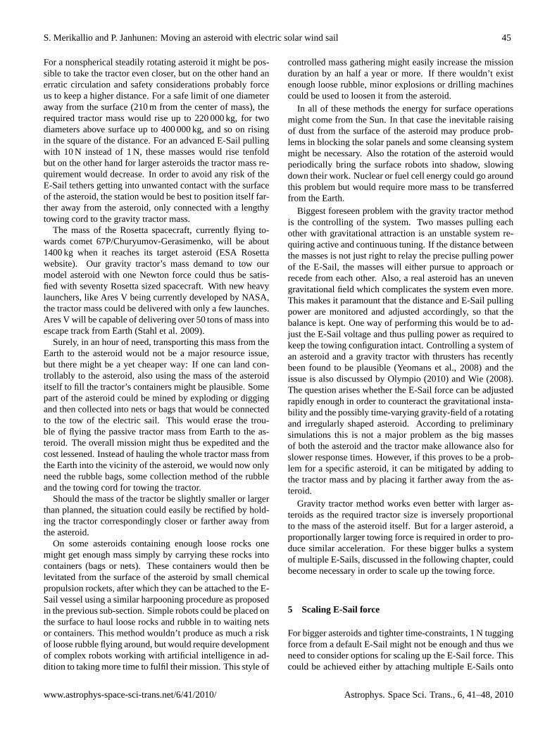
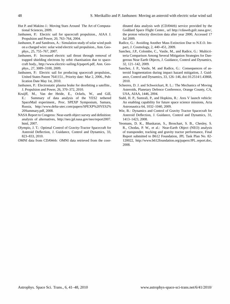
Fig. 3. Connecting E-Sails together in a line is one possibility forscaling up the towing force. Sails do shadow each other, but withlong enough connecting cords losses due to this can be diminished.The towing force (F) is aligned with the towing wire and cuts in halfthe angle between the solar wind (SW) and normal of the sails (n).At maximum this angle can be around 60 degrees for the sail to con-tinue to be effective, giving ample of opportunities for positioningthe sails. Figure is not in scale.
the asteroid and/or by making the E-Sails themselves biggerand more efficient.
In order to attach more E-Sails and thus to scale up theforce, it could be possible to launch several smaller E-Sailstations that would then transfer their pulling power to theasteroid by separate or shared towing cords. This would looklike a cosmic equivalent of towing boats, but would introducetechnical challenges into steering and controls of the E-Sailsto prevent them from clashing with each other. The stabilisa-tion of the rotation of an asteroid might also be an issue. Ifthe rotation is out of control, there is a risk of multiple wiresgetting distorted and knotted. A gravity tractor discussed inthe previous chapter would not have this problem, althoughsome issues might arise with controlling the heavy tractormass itself.
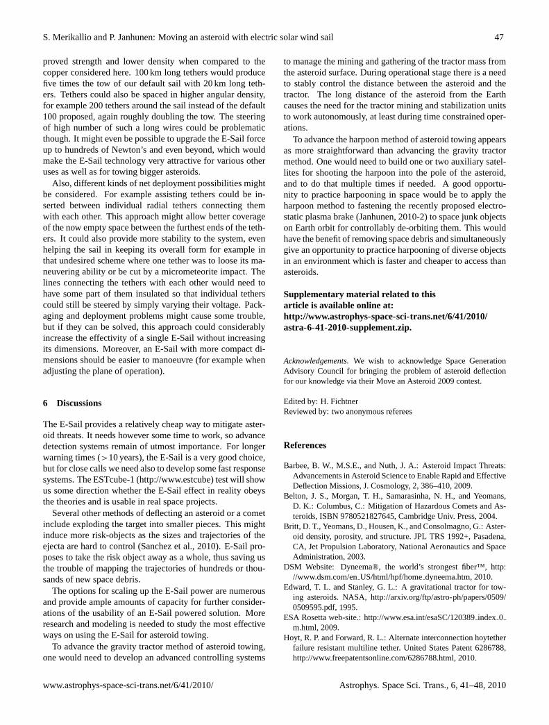
The best option though might be to tie several E-sails ontothe same towing cord (Fig. 3). This would only demand oneattachment point on the asteroid (which could be achievedwith either a gravity tractor or by a harpoon close to the
10 20 30 40 50 600
100
200
300
400
500Minimum connecting cord length between E−Sails for no shadowing
cord
leng
th [k
m]
operating angle (n,SW)
20 km50 km100 km
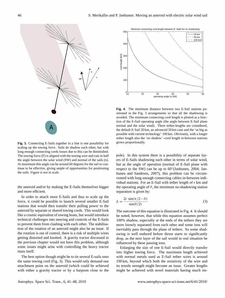
Fig. 4. The minimum distance between two E-Sail stations po-sitioned in the Fig. 3 arrangements so that all the shadowing isavoided. The minimum connecting cord length is plotted as a func-tion of the E-Sail operating angle (the angle between E-Sail planenormal and the solar wind). Three tether-lengths are considered,the default E-Sail 20 km, an advanced 50 km case and the ‘as big aspossible with current technology’ 100 km. Obviously, with a longertether length also the ‘no shadow’ -cord length in-between stationsgrows proportionally.
pole). In this system there is a possibility of separate lay-ers of E-Sails shadowing each other in terms of solar wind,but as the angle of operation (normal of E-Sail plane withrespect to the SW) can be up to 60◦(Janhunen, 2004; Jan-hunen and Sandroos, 2007), this problem can be circum-vented with long enough connecting cables in-between indi-vidual stations. For an E-Sail with tether length ofr km andthe operating angle ofθ , the minimum no-shadowing stationseparation is given by:
L =2r sin(π/2−θ)
sin(θ/2)(3)
The outcome of this equation is illustrated in Fig. 4. It shouldbe noted, however, that while this equation assumes perfect100% shadow, especially at the ends of the tethers they aremore loosely separated from each other and some ions willinevitably pass through the plane of tethers. So some shad-owing is well endured before thrust starts to significantlydrop, as the next layer of the sail would in real situation beinfluenced by these passing ions.
Enlarging the size of one E-Sail would directly transferinto higher towing force. The maximum length achievedwith normal metals used as E-Sail tether wires is around100 km, beyond which both the resistivity of the wire andits tensile strength might become an issue. Greater lengthsmight be achieved with novel materials having much im-
Astrophys. Space Sci. Trans., 6, 41–48, 2010 www.astrophys-space-sci-trans.net/6/41/2010/
S. Merikallio and P. Janhunen: Moving an asteroid with electric solar wind sail 47
proved strength and lower density when compared to thecopper considered here. 100 km long tethers would producefive times the tow of our default sail with 20 km long teth-ers. Tethers could also be spaced in higher angular density,for example 200 tethers around the sail instead of the default100 proposed, again roughly doubling the tow. The steeringof high number of such a long wires could be problematicthough. It might even be possible to upgrade the E-Sail forceup to hundreds of Newton’s and even beyond, which wouldmake the E-Sail technology very attractive for various otheruses as well as for towing bigger asteroids.
Also, different kinds of net deployment possibilities mightbe considered. For example assisting tethers could be in-serted between individual radial tethers connecting themwith each other. This approach might allow better coverageof the now empty space between the furthest ends of the teth-ers. It could also provide more stability to the system, evenhelping the sail in keeping its overall form for example inthat undesired scheme where one tether was to loose its ma-neuvering ability or be cut by a micrometeorite impact. Thelines connecting the tethers with each other would need tohave some part of them insulated so that individual tetherscould still be steered by simply varying their voltage. Pack-aging and deployment problems might cause some trouble,but if they can be solved, this approach could considerablyincrease the effectivity of a single E-Sail without increasingits dimensions. Moreover, an E-Sail with more compact di-mensions should be easier to manoeuvre (for example whenadjusting the plane of operation).
6 Discussions
The E-Sail provides a relatively cheap way to mitigate aster-oid threats. It needs however some time to work, so advancedetection systems remain of utmost importance. For longerwarning times (>10 years), the E-Sail is a very good choice,but for close calls we need also to develop some fast responsesystems. The ESTcube-1 (http://www.estcube) test will showus some direction whether the E-Sail effect in reality obeysthe theories and is usable in real space projects.
Several other methods of deflecting an asteroid or a cometinclude exploding the target into smaller pieces. This mightinduce more risk-objects as the sizes and trajectories of theejecta are hard to control (Sanchez et al., 2010). E-Sail pro-poses to take the risk object away as a whole, thus saving usthe trouble of mapping the trajectories of hundreds or thou-sands of new space debris.
The options for scaling up the E-Sail power are numerousand provide ample amounts of capacity for further consider-ations of the usability of an E-Sail powered solution. Moreresearch and modeling is needed to study the most effectiveways on using the E-Sail for asteroid towing.
To advance the gravity tractor method of asteroid towing,one would need to develop an advanced controlling systems
to manage the mining and gathering of the tractor mass fromthe asteroid surface. During operational stage there is a needto stably control the distance between the asteroid and thetractor. The long distance of the asteroid from the Earthcauses the need for the tractor mining and stabilization unitsto work autonomously, at least during time constrained oper-ations.
To advance the harpoon method of asteroid towing appearsas more straightforward than advancing the gravity tractormethod. One would need to build one or two auxiliary satel-lites for shooting the harpoon into the pole of the asteroid,and to do that multiple times if needed. A good opportu-nity to practice harpooning in space would be to apply theharpoon method to fastening the recently proposed electro-static plasma brake (Janhunen, 2010-2) to space junk objectson Earth orbit for controllably de-orbiting them. This wouldhave the benefit of removing space debris and simultaneouslygive an opportunity to practice harpooning of diverse objectsin an environment which is faster and cheaper to access thanasteroids.
Supplementary material related to thisarticle is available online at:http://www.astrophys-space-sci-trans.net/6/41/2010/astra-6-41-2010-supplement.zip.
Acknowledgements.We wish to acknowledge Space GenerationAdvisory Council for bringing the problem of asteroid deflectionfor our knowledge via their Move an Asteroid 2009 contest.
Edited by: H. FichtnerReviewed by: two anonymous referees
References
Barbee, B. W., M.S.E., and Nuth, J. A.: Asteroid Impact Threats:Advancements in Asteroid Science to Enable Rapid and EffectiveDeflection Missions, J. Cosmology, 2, 386–410, 2009.
Belton, J. S., Morgan, T. H., Samarasinha, N. H., and Yeomans,D. K.: Columbus, C.: Mitigation of Hazardous Comets and As-teroids, ISBN 9780521827645, Cambridge Univ. Press, 2004.
Britt, D. T., Yeomans, D., Housen, K., and Consolmagno, G.: Aster-oid density, porosity, and structure. JPL TRS 1992+, Pasadena,CA, Jet Propulsion Laboratory, National Aeronautics and SpaceAdministration, 2003.
DSM Website: Dyneema®, the world’s strongest fiber™,http://www.dsm.com/enUS/html/hpf/homedyneema.htm, 2010.
Edward, T. L. and Stanley, G. L.: A gravitational tractor for tow-ing asteroids. NASA,http://arxiv.org/ftp/astro-ph/papers/0509/0509595.pdf, 1995.
ESA Rosetta web-site.:http://www.esa.int/esaSC/120389index 0m.html, 2009.
Hoyt, R. P. and Forward, R. L.: Alternate interconnection hoytetherfailure resistant multiline tether. United States Patent 6286788,http://www.freepatentsonline.com/6286788.html, 2010.
www.astrophys-space-sci-trans.net/6/41/2010/ Astrophys. Space Sci. Trans., 6, 41–48, 2010
48 S. Merikallio and P. Janhunen: Moving an asteroid with electric solar wind sail
Hut P. and Makino J.: Moving Stars Around The Art of Computa-tional Sciences, 2009.
Janhunen, P.: Electric sail for spacecraft propulsion., AIAA J.Propulsion and Power, 20, 763–764, 2004.
Janhunen, P. and Sandroos, A.: Simulation study of solar wind pushon a charged wire: solar wind electric sail propulsion., Ann. Geo-phys., 25, 755–767, 2007.
Janhunen, P.: Increased electric sail thrust through removal oftrapped shielding electrons by orbit chaotisation due to space-craft body.,http://www.electric-sailing.fi/paper6.pdf, Ann. Geo-phys., 27, 3089–3100, 2009.
Janhunen, P.: Electric sail for producing spacecraft propulsion.,United States Patent 7641151., Priority date: Mar 2, 2006., Pub-lication Date May 1st, 2010.
Janhunen, P.: Electrostatic plasma brake for deorbiting a satellite.,J. Propulsion and Power, 26, 370–372, 2010.
Kruijff, M., Van der Heide, E., Ockels, W., and Gill,E.: Summary of data analysis of the YES2 tetheredSpaceMail experiment., Proc. SPEXP Symposium, Samara,Russia, http://www.delta-utec.com/papers/SPEXP%20YES2%20Summary.pdf, 2008.
NASA Report to Congress: Near-earth object survey and definition:analysis of alternatives,http://neo.jpl.nasa.gov/neo/report2007.html, 2007.
Olympio, J. T.: Optimal Control of Gravity-Tractor Spacecraft forAsteroid Deflection, J. Guidance, Control and Dynamics, 33,823–833, 2010.
OMNI data from CDAWeb: OMNI data retrieved from the coor-
dinated data analysis web (CDAWeb) service provided by theGoddard Space Flight Center., url http://cdaweb.gsfc.nasa.gov/,the proton velocity direction data after year 2000, Accessed 17Jul 2009.
Radice, G.: Avoiding Another Mass Extinction Due to N.E.O. Im-pact, J. Cosmology, 2, 440–451, 2009.
Sanchez, J.P., Colombo, C., Vasile, M., and Radice, G.: Multicri-teria Comparison Among Several Mitigation Strategies for Dan-gerous Near Earth Objects, J. Guidance, Control and Dynamics,32, 121–142, 2009.
Sanchez, J. P., Vasile, M. and Radice, G.: Consequences of as-teroid fragmentation during impact hazard mitigation, J. Guid-ance, Control and Dynamics, 33, 126–146, doi:10.2514/1.43868,2010.
Scheeres, D. J. and Schweickart, R. L.: The Mechanics of MovingAsteroids, Planetary Defence Conference, Orange County, CA,USA, AIAA, 1446, 2004.
Stahl, H. P., Sumrali, P., and Hopkins, R.: Ares V launch vehicle:An enabling capability for future space science missions, ActaAstronautica 64, 1032–1040, 2009.
Wie, B.: Dynamics and Control of Gravity Tractor Spacecraft forAsteroid Deflection, J. Guidance, Control and Dynamics, 31,1413–1423, 2008.
Yeomans, D. K., Bhaskaran, S., Broschart, S. B., Chesley, S.R., Chodas, P. W., et al.: Near-Earth Object (NEO) analysisof transponder, tracking and gravity tractor performance, FinalReport submitted to B612 Foundation, JPL Task Plan No. 82-120022,http://www.b612foundation.org/papers/JPLreport.doc,2008.
Astrophys. Space Sci. Trans., 6, 41–48, 2010 www.astrophys-space-sci-trans.net/6/41/2010/