MOVIFIT®-FC special design for dual-motor operation ... · M11 = Stainless steel mounting rail...
32
Drive Technology \ Drive Automation \ System Integration \ Services Special Design MOVIFIT ® -FC for Dual-Motor Operation Addendum to the Operating Instructions Edition 03/2009 16784413 / EN
Transcript of MOVIFIT®-FC special design for dual-motor operation ... · M11 = Stainless steel mounting rail...

Drive Technology \ Drive Automation \ System Integration \ Services
Special DesignMOVIFIT®-FC for Dual-Motor Operation
Addendum to the Operating InstructionsEdition 03/200916784413 / EN

SEW-EURODRIVE – Driving the world

Addendum to the Operating Instructions – MOVIFIT®-FC for Dual-Motor Operation 3
Content
Content1 General Information ............................................................................................ 4
1.1 Structure of the safety notes ....................................................................... 41.2 Rights to claim under limited warranty ........................................................ 51.3 Exclusion of liability..................................................................................... 51.4 Other applicable documentation ................................................................. 5
2 Unit Structure ...................................................................................................... 62.1 Special design "MOVIFIT-FC for dual-motor operation" ............................. 62.2 Accessories................................................................................................. 8
3 Electrical Installation .......................................................................................... 93.1 Fieldbus/option-independent terminal assignment ..................................... 93.2 Replacing switching relays........................................................................ 13
4 Startup................................................................................................................ 144.1 Startup procedure for MOVIFIT®-FC ........................................................ 144.2 Preparations.............................................................................................. 154.3 Motor/brake startup with MOVIFIT®-FC.................................................... 184.4 Switchover between drive 1 and drive 2 ................................................... 30

4 Addendum to the Operating Instructions – MOVIFIT®-FC for Dual-Motor Operation
1 Structure of the safety notesGeneral Information
1 General Information1.1 Structure of the safety notes
The safety notes in these operating instructions are designed as follows:
Pictogram SIGNAL WORDType and source of danger.
Possible consequence(s) if the safety notes are disregarded.• Measure(s) to prevent the danger.
Pictogram Signal word Meaning Consequences if disregarded
Example:
General danger
Specific danger,e.g. electric shock
DANGER Imminent danger Severe or fatal injuries
WARNING Possible dangerous situation Severe or fatal injuries
CAUTION Possible dangerous situation Minor injuries
NOTICE Possible damage to property Damage to the drive system or its environ-ment
TIP Useful information or tip.Simplifies the handling of the drive system.

Addendum to the Operating Instructions – MOVIFIT®-FC for Dual-Motor Operation 5
1Rights to claim under limited warrantyGeneral Information
1.2 Rights to claim under limited warrantyA requirement of fault-free operation and fulfillment of any rights to claim under limitedwarranty is that you adhere to the information in the operating instructions. Therefore,read the operating instructions before you start working with the unit
Make sure that the operating instructions are legible and available to persons responsi-ble for the plant and its operation, as well as to persons who work independently on theunit.
1.3 Exclusion of liabilityYou must comply with the information contained in these operating instructions to en-sure safe operation of MOVIFIT®-FC and to achieve the specified product and perfor-mance features. SEW-EURODRIVE assumes no liability for injury to persons or dam-age to equipment or property resulting from non-observance of these operating instruc-tions. In such cases, any liability for defects is excluded.
1.4 Other applicable documentation• This additional information does not replace the detailed operating instructions and
manual.
• Installation and startup only by trained personnel observing the relevant accidentprevention regulations and the following publications:
• "MOVIFIT®-FC" operating instructions
and
• "MOVIFIT® functional safety" manual
and
• "MOVIFIT® Function Level Classic ..." manual
or
• "MOVIFIT® Function Level Technology ..." manual

6 Addendum to the Operating Instructions – MOVIFIT®-FC for Dual-Motor Operation
2 Special design "MOVIFIT-FC for dual-motor operation"Unit Structure
2 Unit Structure2.1 Special design "MOVIFIT-FC for dual-motor operation"
The following figure shows the connection board of the special design "MOVIFIT®-FCfor dual-motor operation":
TIPSThis special design ""MTA...-S..-30." comprises the following changes on the connec-tion box compared to the standard design:• Modified connection assignment of the ABOX.• Only TH bimetallic switch can be connected.• Only SEW-EURODRIVE motors and brakes can be controlled.• Integrated K1/K2/K3 relay for switching between drive 1 and drive 2.
The relays have a service life of 1.000.000 switching cycles. The relays have to be replaced after that.
• The binary output DB00 is not available.• This special design is not allowed for hoist operation.
1737858315
X1 X9 X8X10 X81 X20 X45 X25 X30 X31 X35 X50X29
K1
K3K2
Addendum to the Operating Instructions – MOVIFIT®-FC for Dual-Motor Operation 7
2Special design "MOVIFIT-FC for dual-motor operation"Unit Structure
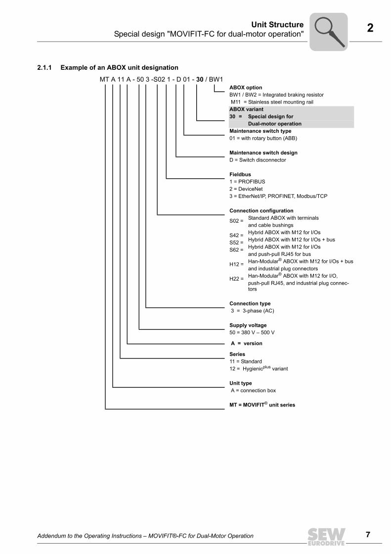
2.1.1 Example of an ABOX unit designation
MT A 11 A - 50 3 -S02 1 - D 01 - 30 / BW1ABOX optionBW1 / BW2 = Integrated braking resistor M11 = Stainless steel mounting railABOX variant 30 = Special design for
Dual-motor operationMaintenance switch type 01 = with rotary button (ABB)
Maintenance switch design D = Switch disconnector
Fieldbus 1 = PROFIBUS2 = DeviceNet3 = EtherNet/IP, PROFINET, Modbus/TCP
Connection configuration
S02 =
S42 =S52 =S62 =
H12 =
H22 =
Standard ABOX with terminalsand cable bushingsHybrid ABOX with M12 for I/OsHybrid ABOX with M12 for I/Os + busHybrid ABOX with M12 for I/Osand push-pull RJ45 for busHan-Modular® ABOX with M12 for I/Os + busand industrial plug connectorsHan-Modular® ABOX with M12 for I/O,push-pull RJ45, and industrial plug connec-tors
Connection type 3 = 3-phase (AC)
Supply voltage 50 = 380 V – 500 V
A = version
Series 11 = Standard12 = Hygienicplus variant
Unit type A = connection box
MT = MOVIFIT® unit series

8 Addendum to the Operating Instructions – MOVIFIT®-FC for Dual-Motor Operation
2 AccessoriesUnit Structure
2.2 AccessoriesThe following accessories are required for replacing faulty relays.
The relays can also be replaced during maintenance to increase system availability.
The accessories are available from SEW-EURODRIVE.
Type Figure Content Part number
Switching relay including support bracket
3 pc 1 821 747 8
30 pc 1 821 748 6
+

Addendum to the Operating Instructions – MOVIFIT®-FC for Dual-Motor Operation 9
3Fieldbus/option-independent terminal assignmentElectrical Installation
3 Electrical Installation
3.1 Fieldbus/option-independent terminal assignment
TIPS• The following section describes the modified connection assignment of the ABOX. • For the terminal assignment of all terminals that are not described here, refer to the
"MOVIFIT®-FC" operating instructions.• Observe the "MOVIFIT®-FC" operating instructions, in particular the safety and
warning notes.
DANGERThe maintenance switch only disconnects the integrated frequency inverter from thesupply system. Voltage is still present on the terminals of the MOVIFIT® unit.
Severe or fatal injuries from electric shock.• Switch off the power to the MOVIFIT® using a suitable external disconnecting
device, and wait at least 1 minute before opening the wiring space.
1739094539
Line terminal (power bus)
No. Name Function
X1 1 PE Line connection PE (IN)
2 L1 Line connection phase L1 (IN)
3 L2 Line connection phase L2 (IN)
4 L3 Line connection phase L3 (IN)
11 PE Line connection PE (OUT)
12 L1 Line connection phase L1 (OUT)
13 L2 Line connection phase L2 (OUT)
14 L3 Line connection phase L3 (OUT)
X8
K1
K2
K3
1 2 3
5 6 7
5 6 7
4
1 2 3 41 2
X9
X8
X9
X10
X20
1
11 12 13 15 16
2 3 5 6
X81X29
X45 X25
X35
1 2 3 4
1 2 3
1 2 3
1 2 3 4 5
11 22 33 44 5 1 2 33 4 5 6 7 8
11 12 13 14 15
21 22 23 24 25
31 32 33 34 35
11 12 13 14 15 16 17 18
21 22 23 24 25 26 27 28
31 32 33 34 35 36 37 38
6 7 8
1 2 3 4 5
11 12 13 14 15
S3
X50
S1
S2
X31
X30
X1
1 2 3 4
11 12 13 14

10 Addendum to the Operating Instructions – MOVIFIT®-FC for Dual-Motor Operation
3 Fieldbus/option-independent terminal assignmentElectrical Installation
1741520651
24 V supply terminal (24 V power bus)
No. Name Function
X20 1 FE Functional earth (IN)
2 +24V_C +24 V continuous voltage supply (IN)
3 0V24_C 0V24 reference potential - continuous voltage (IN)
5 +24V_S +24 V supply – switched (IN)
6 0V24_S 0V24 reference potential – switched (IN)
11 FE Functional earth (OUT)
12 +24V_C +24 V continuous voltage supply (OUT)
13 0V24_C 0V24 reference potential - continuous voltage (OUT)
15 +24V_S +24 V supply – switched (OUT)
16 0V24_S 0V24 reference potential – switched (OUT)
X8
K1
K2
K3
1 2
1 2
3
5 6 7
5 6 7
4
1 2 3 4
X9
X8
X9
X10
X1
1 2 3 4
11 121 131 14
X81X29
X45 X25
X35
1 2 3 4
1 2 3
1 2 3
1 2 3 4 5
11 22 33 44 5 1 2 33 4 5 6 7 8
11 12 13 14 15
21 22 23 24 25
31 32 33 34 35
11 12 13 14 15 16 17 18
21 22 23 24 25 26 27 28
31 32 33 34 35 36 37 38
6 7 8
1 2 3 4 5
11 12 13 14 15
S3
X50
S1
S2
X31
X30
X20
1
11 12 13 15 16
2 3 5 6

Addendum to the Operating Instructions – MOVIFIT®-FC for Dual-Motor Operation 11
3Fieldbus/option-independent terminal assignmentElectrical Installation
1741527563
Motor connection terminal (connection via hybrid cable)
No. Name Function
X8 1 PE Motor 1 PE connection
2 U Output motor 1 phase U
3 V Output motor 1 phase V
4 W Output motor 1 phase W
5 15 Connection for SEW brake motor 1 terminal 15 (blue)
6 14 Connection for SEW brake motor 1 terminal 14 (white)
7 13 Connection for SEW brake motor 1 terminal 13 (red)
X9 1 PE Motor 2 PE connection
2 U Output motor 2 phase U
3 V Output motor 2 phase V
4 W Output motor 2 phase W
5 15 Connection for SEW brake motor 2 terminal 15 (blue)
6 14 Connection for SEW brake motor 2 terminal 14 (white)
7 13 Connection for SEW brake motor 2 terminal 13 (red)
X81 1 TH+ Connection for temperature sensor TH (+) motor 1
2 TH Connection for temperature sensor TH (-) motor 1
3 TH+ Connection for temperature sensor TH (+) motor 2
4 TH Connection for temperature sensor TH (-) motor 2
X10 1 -R Braking resistor connection -R
2 +R Braking resistor connection +R
X20
1
11 12 13 15 16
2 3 5 6
X1
1 2 3 4
11 121 131 14
X29
X45 X25
X35
K1
K2
K3
1 2 3
1 2 3
1 2 3 4 5
11 22 33 44 5 1 2 33 4 5 6 7 8
11 12 13 14 15
21 22 23 24 25
31 32 33 34 35
11 12 13 14 15 16 17 18
21 22 23 24 25 26 27 28
31 32 33 34 35 36 37 38
6 7 8
1 2 3 4 5
11 12 13 14 15
S3
X50
S1
S2
X31
X30X8
1 2 3 4
1 2 3 4
5 6 7
5 6 7
1 2
X10 X9
X8
X9
X81
1 2 3 4
12 Addendum to the Operating Instructions – MOVIFIT®-FC for Dual-Motor Operation
3 Fieldbus/option-independent terminal assignmentElectrical Installation
1741533579
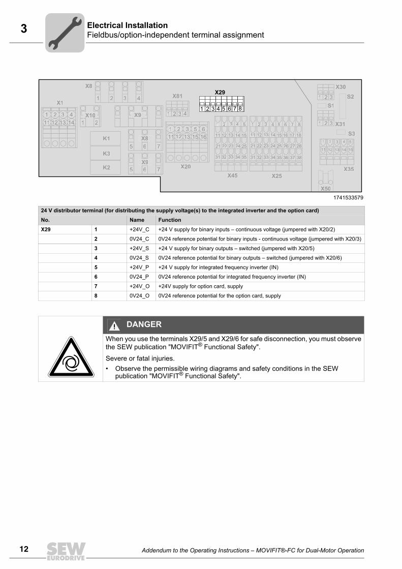
24 V distributor terminal (for distributing the supply voltage(s) to the integrated inverter and the option card)
No. Name Function
X29 1 +24V_C +24 V supply for binary inputs – continuous voltage (jumpered with X20/2)
2 0V24_C 0V24 reference potential for binary inputs - continuous voltage (jumpered with X20/3)
3 +24V_S +24 V supply for binary outputs – switched (jumpered with X20/5)
4 0V24_S 0V24 reference potential for binary outputs – switched (jumpered with X20/6)
5 +24V_P +24 V supply for integrated frequency inverter (IN)
6 0V24_P 0V24 reference potential for integrated frequency inverter (IN)
7 +24V_O +24V supply for option card, supply
8 0V24_O 0V24 reference potential for the option card, supply
X1
1 2 3 4
11 121 131 14
K1
K2
K3
X8
1 2 3 4
5 6 7
5 6 7
X9
X8
1 2
X9
X10
X20
1
11 12 13 15 16
2 3 5 6
X81
X45 X25
X35
1 2 3 4
1 2 3
1 2 311 22 33 44 5 1 2 33 4 5 6 7 8
11 12 13 14 15
21 22 23 24 25
31 32 33 34 35
11 12 13 14 15 16 17 18
21 22 23 24 25 26 27 28
31 32 33 34 35 36 37 38
1 2 3 4 5
11 12 13 14 15
S3
X50
S1
S2
X31
X30
X29
1 2 3 4 5 6 7 8
DANGERWhen you use the terminals X29/5 and X29/6 for safe disconnection, you must observethe SEW publication "MOVIFIT® Functional Safety".
Severe or fatal injuries.• Observe the permissible wiring diagrams and safety conditions in the SEW
publication "MOVIFIT® Functional Safety".

Addendum to the Operating Instructions – MOVIFIT®-FC for Dual-Motor Operation 13
3Replacing switching relaysElectrical Installation
3.2 Replacing switching relaysYou can replace the K1, K2 or K3 switching relays as follows:
1. Remove the support brackets of the relay.
2. Carefully remove the relay in upward direction.
Important: Make sure you do not tilt the relay to prevent the socket and its pinsfrom being damaged.
3. Replace the faulty relay by the new one and install the parts in reverse order.
Make sure you do not damage the new relay when inserting it.
-
DANGERDisconnect the units from power before installing/removing the relay. Dangerous volt-ages may still be present for up to one minute after disconnection from the power sup-ply.
Severe or fatal injuries from electric shock.• Disconnect the MOVIFIT® from the mains using an appropriate external discon-
necting device and secure it against unintentional reconnection to the voltage sup-ply.
• Then wait at least for 1 minute.
1741934859
90°
1. 2. 3.
TIPSEW-EURODRIVE recommends to replace all 3 relays to increase system availability.

14 Addendum to the Operating Instructions – MOVIFIT®-FC for Dual-Motor Operation
4Startup procedure for MOVIFIT®-FCStartup
4 Startup4.1 Startup procedure for MOVIFIT®-FC
The following sections describe how to startup the special design MOVIFIT®-FC motor.Observe the additional documents listed in the following table:
792881803
Function level
1.StartupMotor
2.Startup
MOVIFIT®-FC
3.Parameterization1)
Programming
1) You only have to set parameters when the "Expert" mode is activated.
4.Fieldbus
configuration
Classic Observe:• -"DR/DV/DT/DTE/
DVE AC Motors, CT/CV Asynchro-nous Servomotors" operating instruc-tions
• or "AC Motors DRS/DRE/DRP" operat-ing instructions
Observe the "MOVIFIT®-FC" operating instruc-tions
Manual -"MOVIFIT® function level Classic..."2)
2) The "MOVIFIT® Function Level Classic" and "MOVIFIT® Function Level Technology" manuals are avail-able in several fieldbus-specific variants.
Technology Manual"MOVIFIT® function levelTechnology .."2)
"MOVI-PLC® Pro-gramming in the PLC Editor" manualManual "Libraries MPLCMotion_MC07 andMPLCMotion_MM for MOVI-PLC®"
System Manual"Configuration and Diagnostic ToolMOVIVISION®"
Manual-"MOVIFIT® Function Level System"
Motor
1. 2. 4.
MOVIFIT®-SC/-FC Parameterization
Programming
3.
Fieldbus configuration
DANGERIf you are using applications with safe disconnection, you must additionally observe theSEW publication "MOVIFIT® Functional Safety".
Severe or fatal injuries.• Observe the additional startup notes and safety conditions in the SEW publication
"MOVIFIT® Functional Safety".
00
I

Addendum to the Operating Instructions – MOVIFIT®-FC for Dual-Motor Operation 15
4PreparationsStartup
4.2 Preparations4.2.1 MOVITOOLS® MotionStudio
The "MOVITOOLS® MotionStudio" software package is the SEW engineering tool thatyou can use to access all SEW drive units. With simple applications, you can useMOVITOOLS® MotionStudio to perform diagnostics for the MOVIFIT® unit series. Formore demanding applications, you can use the wizards available in MOVITOOLS® Mo-tionStudio to startup, configure and program MOVIFIT® units.
MOVITOOLS® MotionStudio can communicate with the drive units using different com-munication links and fieldbus systems.
The most simple application for connecting a PC/laptop and a MOVIFIT® unit via the di-agnostics interface (serial RS485) (point-to-point connection) is described in the follow-ing section:
Preparations on MOVIFIT®
1. Always follow the safety and warning instructions in the relevant operating in-structions when working on MOVIFIT® units.
2. Install the latest software version of MOVITOOLS® MotionStudio on your PC/laptop.
3. Set DIP switch S10/1 to "ON" (activating "Expert mode")
837925643
1 65432
S10 ON
00
I
16 Addendum to the Operating Instructions – MOVIFIT®-FC for Dual-Motor Operation
4 PreparationsStartup
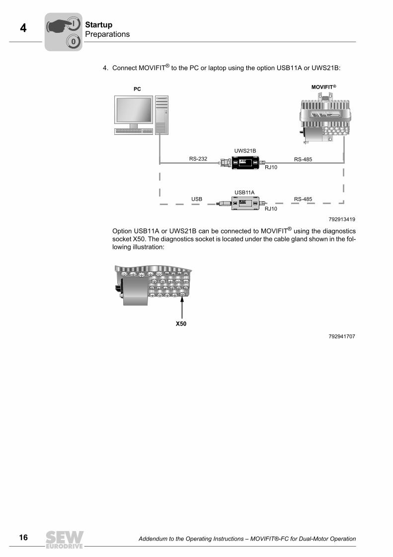
4. Connect MOVIFIT® to the PC or laptop using the option USB11A or UWS21B:
Option USB11A or UWS21B can be connected to MOVIFIT® using the diagnosticssocket X50. The diagnostics socket is located under the cable gland shown in the fol-lowing illustration:
792913419
792941707
DI01
DI00
DI02
DI03
DI04
DI05
DI06/D
O00
DI07/D
O01
SYS-F
BU
S-F
24V-C
24V-S
RU
N
RU
N-P
S
MOVIFIT®PC
UWS21B
RS-232
USB
USB11A
RJ10
RS-485
RS-485
RJ10
X50
00
I

Addendum to the Operating Instructions – MOVIFIT®-FC for Dual-Motor Operation 17
4PreparationsStartup
Including MOVIFIT® in MOVITOOLS® MotionStudioStarting the soft-ware and creating a project
Proceed as follows to start MOVITOOLS® MotionStudio and create a project:
1. Start the MOVITOOLS® MotionStudio from the Windows start menu via:
[Start]/[Programs]/[SEW]/[MOVITOOLS-MotionStudio]/[MOVITOOLS-MotionStudio]
2. Create a project with name and storage location.
Establishing com-munication and scanning the net-work
Proceed as follows to establish a communication with MOVITOOLS® MotionStudio andscan your network:
1. Set up a communication channel to communicate with your units.
For detailed information on how to configure a communication channel, see the sec-tion regarding the relevant communication type.
2. Scan your network (unit scan). Press the [Start network scan] button [1] in the tool-bar.
3. Select the unit you want to configure.
4. Right-click to open the context menu.
As a result you will see a number of unit-specific tools to execute various functionswith the units. These are, for example:
– Bus monitor
– Startup
– Parameterization
00
I

18 Addendum to the Operating Instructions – MOVIFIT®-FC for Dual-Motor Operation
4Motor/brake startup with MOVIFIT®-FCStartup
4.3 Motor/brake startup with MOVIFIT®-FC
4.3.1 Starting up drive 1 1. Choose the startup tool in MOVITOOLS® MotionStudio (see section "Including
MOVIFIT® in MOVITOOLS® MotionStudio"). The window for selecting the parameterset opens.
2. Parameter set 1 must be selected for drive 1.
TIP"Expert mode" (S10/1 = "ON") must be active for the following motor/brake startup pro-cedure.
792943371
00
I

Addendum to the Operating Instructions – MOVIFIT®-FC for Dual-Motor Operation 19
4Motor/brake startup with MOVIFIT®-FC
Startup
3. After you have selected the parameter set, an overview displaying the current unitinformation is displayed (display values only):
4. Select the configuration for the motor output:
• Activate the "Switchable" checkbox.
792945035
1771084939
00
I

20 Addendum to the Operating Instructions – MOVIFIT®-FC for Dual-Motor Operation
4Motor/brake startup with MOVIFIT®-FCStartup
5. Select the system configuration:
• With "one motor", MOVIFIT®-FC controls a single motor.
• With "rigid coupling", MOVIFIT®-FC controls several motors that are rigidlycoupled via the axes.
• With "no/loose coupling", MOVIFIT®-FC controls several motors that are not oreloosely coupled via the axes.
With "rigid coupling" or "no/loose coupling", you will have to select the alternativebrake control "Via constant voltage" in the "Brake" menu.
"Different" is not possible for MOVIFIT® units.
792948363
00
I
Addendum to the Operating Instructions – MOVIFIT®-FC for Dual-Motor Operation 21
4Motor/brake startup with MOVIFIT®-FC
Startup
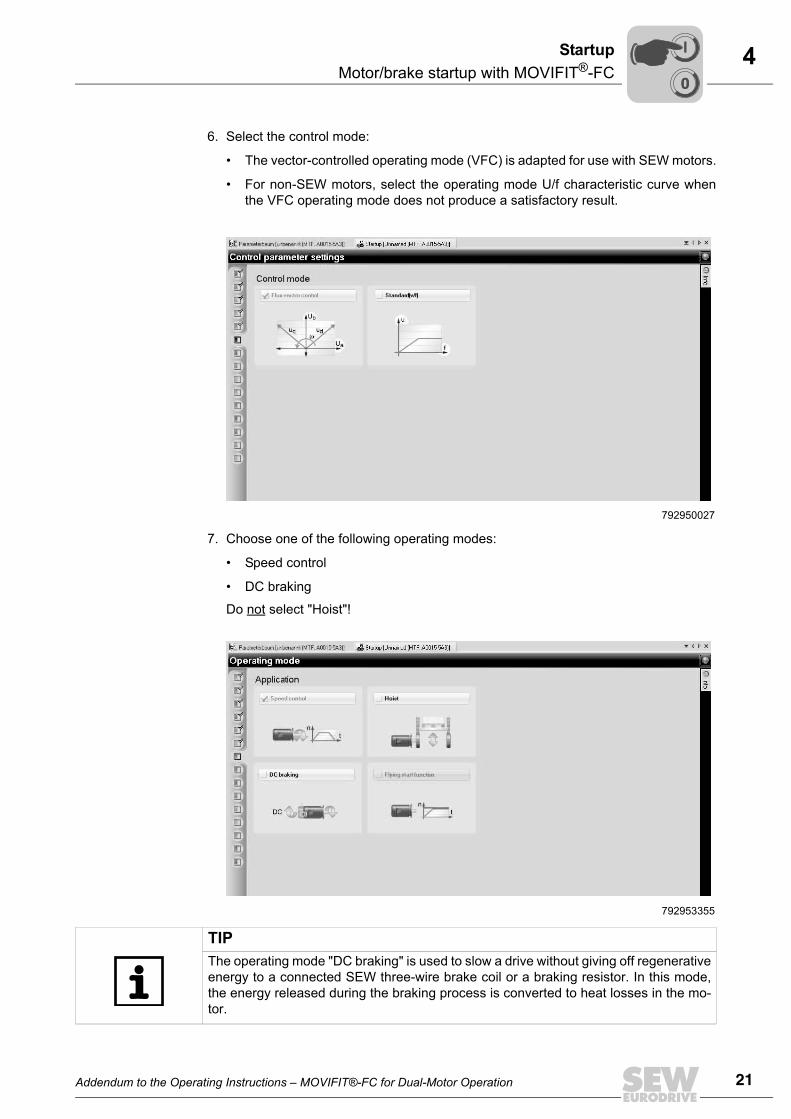
6. Select the control mode:
• The vector-controlled operating mode (VFC) is adapted for use with SEW motors.
• For non-SEW motors, select the operating mode U/f characteristic curve whenthe VFC operating mode does not produce a satisfactory result.
7. Choose one of the following operating modes:
• Speed control
• DC braking
Do not select "Hoist"!
792950027
792953355
TIPThe operating mode "DC braking" is used to slow a drive without giving off regenerativeenergy to a connected SEW three-wire brake coil or a braking resistor. In this mode,the energy released during the braking process is converted to heat losses in the mo-tor.
00
I

22 Addendum to the Operating Instructions – MOVIFIT®-FC for Dual-Motor Operation
4Motor/brake startup with MOVIFIT®-FCStartup
8. Choose the connected motor.
Standard motors:When selecting an SEW standard motor, select:
• the motor type
• the rated motor voltage (corresponding to the respective type of connection,"Star" or "Delta")
• and the rated motor frequency
Refer to the motor nameplate of the motor.
Non-SEW motors:This special design can control SEW-EURODRIVE motors only. This is why "Non-SEW motor" must not be selected.
792951691
792955019
00
I
Addendum to the Operating Instructions – MOVIFIT®-FC for Dual-Motor Operation 23
4Motor/brake startup with MOVIFIT®-FC
Startup
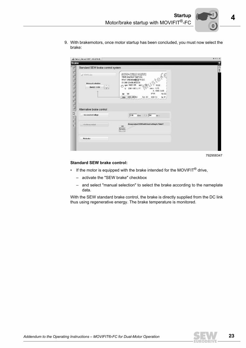
9. With brakemotors, once motor startup has been concluded, you must now select thebrake:
Standard SEW brake control:
• If the motor is equipped with the brake intended for the MOVIFIT® drive,
– activate the "SEW brake" checkbox
– and select "manual selection" to select the brake according to the nameplatedata.
With the SEW standard brake control, the brake is directly supplied from the DC linkthus using regenerative energy. The brake temperature is monitored.
792958347
00
I

24 Addendum to the Operating Instructions – MOVIFIT®-FC for Dual-Motor Operation
4Motor/brake startup with MOVIFIT®-FCStartup
Alternative brake control
The alternative brake control is intended for the case
• that the motor is equipped with a brake different from the one intended for theMOVIFIT® drive (see table on the next page)
• or that several motors/brakes are operated with one MOVIFIT® in parallel. I.e. youhave selected "no/loose coupling" in the "System configuration" window (step 4).In this case, the brakes must have the same rated voltage.
Only the following control method is available:
• Brake control via constant voltage
– Activate the "via constant voltage" checkbox
– Enter the brake supply voltage either as AC or DC voltage
If the motor is not equipped with a brake, activate the "no brake" checkbox.
CAUTIONWhen selecting an alternative brake control, the drive must already be equipped withan internal or external braking resistor. During the brake process, the braking resistordissipates regenerative power.
00
I

Addendum to the Operating Instructions – MOVIFIT®-FC for Dual-Motor Operation 25
4Motor/brake startup with MOVIFIT®-FC
Startup
For DT/DV motors, the brake type is not stated explicitly. You can determine the typeof the installed brake on the basis of the motor size and the specified braking torque(see motor nameplate).
The following table shows the assignment of brake types and braking torques to themotor sizes. The table also lists the reduced braking torques of the brakes.
TIPFor the assignment of MOVIFIT® motors to Standard brakes, refer to the "MOVIFIT®-FC" operating instructions,
chapter "Startup"/"Startup of MOVIFIT® frequency inverters"/"Startup in Easy mode"/"DIP switch10/5".
Braketype
For motorsize
MB max[Nm]
Reduced braking torques MB red[Nm]
BMG02 DT56 1.2 0.8BR03 DR63 3.2 2.4 1.6 0.8BMG05 DT71 / DT80 5.0 4 2.5 1.6 1.2BMG1 DT80 10 7.5 6BMG2 DT90/DV100 20 16 10 6.6 5BMG4 DV100 40 30 24
Example 1:
Designation on the motor nameplate:
Brake V 230VAC 20 Nm for DT90L4
Interpretation using the table:
Motor: DT90
Brake: BMG2 with braking torque MB max = 20 Nm
Example 2:
Designation on the motor nameplate:
Brake V 230VAC 10 Nm for DV100L4
Interpretation using the table:
Motor: DV100
Brake: BMG2 with reduced braking torque MB red = 10 Nm
The BMG4 brake cannot be installed in this example,as the respective braking torque is not listed in theabove table.
00
I

26 Addendum to the Operating Instructions – MOVIFIT®-FC for Dual-Motor Operation
4Motor/brake startup with MOVIFIT®-FCStartup
10.The next step "Application parameters" is used to activate the "Speed monitoring"function and to set the current limit.
When speed monitoring is active, a fault is triggered after the specified decelerationtime when the output current reaches the set current limit continuously.
The percentage current level is based on the rated unit current. The output frequencyis reduced to protect the motor from stalling when the current limit is reached. To en-sure stall protection, accept the default value for the current limit.
Click the black arrow to accept the default values. Click the right mouse button in theinput field to display additional input options.
You can accept each default value individually, or you can accept all default valuesby choosing the "Accept" button.
888384651
00
I

Addendum to the Operating Instructions – MOVIFIT®-FC for Dual-Motor Operation 27
4Motor/brake startup with MOVIFIT®-FC
Startup
11.In the next step parameters are set for the speed limits and ramp times.
The ramp times are always based on a change in the output speed of 1500 rpm. Theramp times apply when a ramp time has not been specified via the process data andan enable/revoke enable occurs. The stop ramp is active when a "Rapid stop" is re-quested or when specific errors occur.
Click the black arrow to accept the default values. Click the right mouse button in theinput field to display additional input options.
You can accept each default value individually, or you can accept all default valuesby choosing the "Accept" button.
903482379
00
I

28 Addendum to the Operating Instructions – MOVIFIT®-FC for Dual-Motor Operation
4Motor/brake startup with MOVIFIT®-FCStartup
12.Click the "Download" or "Finish" button to download the parameters to the unit. Be-fore you download the parameters, you can switch to any of the previous pages. Thesettings are not lost.
906417803
TIPStartup of a hoist drive is not permitted with this special design.
00
I
Addendum to the Operating Instructions – MOVIFIT®-FC for Dual-Motor Operation 29
4Motor/brake startup with MOVIFIT®-FC
Startup
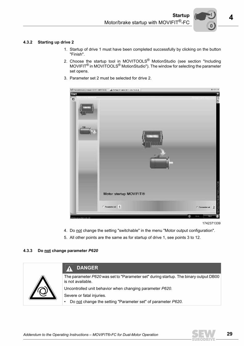
4.3.2 Starting up drive 2
1. Startup of drive 1 must have been completed successfully by clicking on the button"Finish".
2. Choose the startup tool in MOVITOOLS® MotionStudio (see section "IncludingMOVIFIT® in MOVITOOLS® MotionStudio"). The window for selecting the parameterset opens.
3. Parameter set 2 must be selected for drive 2.
4. Do not change the setting "switchable" in the menu "Motor output configuration".
5. All other points are the same as for startup of drive 1, see points 3 to 12.
4.3.3 Do not change parameter P620
1742371339
DANGERThe parameter P620 was set to "Parameter set" during startup. The binary output DB00is not available.
Uncontrolled unit behavior when changing parameter P620.
Severe or fatal injuries.• Do not change the setting "Parameter set" of parameter P620.
00
I

30 Addendum to the Operating Instructions – MOVIFIT®-FC for Dual-Motor Operation
4 Switchover between drive 1 and drive 2Startup
4.4 Switchover between drive 1 and drive 24.4.1 Switching via MOVIFIT®-FC control word-
Bit 5 "Parameter set switchover" in the MOVIFIT®-FC control word is used for switchingbetween drive 1 and drive 2.
The following table shows the functions of the control word for MOVIFIT®-FC.
TIPA switchover is only possible when the output stage is inhibited (evaluation via statusword 1, bit 0, (see page 31)).
The relays have a service life of 1,000,000 switching cycles. The relays have to be re-placed after that.
1742961547
Bit Meaning Explanation
0 Controller inhibit/enable 0: Enable1: Inhibit controller, activate brake
1 Enable/rapid stop 0: Rapid stop1: Enable
2 Enable/stop 0: Stop at normal ramp1: Enable
3 Reserved For reserved bits, the value 0 must be transferred for later use
4 Reserved For reserved bits, the value 0 must be transferred for later use
5 Parameter set switch-over= Switchover between drive 1 and drive 2
0: Parameter set 1 = drive 11: Parameter set 2 = drive 2
6 Fault reset If there is an error in the inverter power section, an error reset is requested by changing this bit from 0 to 1.
7 Reserved For reserved bits, the value 0 must be transferred for later use
8 Brake release without drive enable
This function is not active in Easy mode. The functionality is acti-vated by setting an additional parameter.
1: Release brake without drive enable0: Do not release brake
9–15 Reserved For reserved bits, the value 0 must be transferred for later use
15 14 13 12 11 10 9 8 7 6 5 4 3 2 1 0
Byte n+1 Byte n
8: Brake release without drive enable
9 – 15: Reserved = 0
0: Controller inhibit/enable
1: Enable/rapid stop
2: Enable/stop
3..4: Reserved = 0
5: Parameter set change
6: Reset
7: Reserved = 0
00
I

Addendum to the Operating Instructions – MOVIFIT®-FC for Dual-Motor Operation 31
4Switchover between drive 1 and drive 2Startup
4.4.2 Evaluation via status word 1 for MOVIFIT®-FC
Bit 4 "Current parameter set" in the MOVIFIT®-FC status word 1 is used for determiningwhich drive has been activated via the control word:
The following table shows the assignment of status word 1 for MOVIFIT®-FC:
1742971915
Bit Meaning Explanation
0 Output stage enabled 1: MOVIFIT® inverter output stage is enabled0: MOVIFIT® inverter output stage is not enabled
1 Inverter ready 1: Inverter power section is ready for operation0: Inverter power section is not ready for operation
2 PO data enabled 1: Process data is enabled; Drive can be controlled via fieldbus0: Process data is inhibited; Drive cannot be controlled via fieldbus
3 Reserved For reserved bits, the value 0 is transferred for later use
4 Current parameter set = activated drive
0: Parameter set 1 = drive 11: Parameter set 2 = drive 2
5 Fault/warning 1: Fault/warning present0: OK
6 Reserved For reserved bits, the value 0 is transferred for later use
7 Reserved For reserved bits, the value 0 is transferred for later use
8–15 Bit 5 = 0: Unit status0: 24 V operation1: Controller inhibit2: No enable3: Standstill current4: EnableBit 5 = 1: Error number
If there is no fault/warning (bit 5 = 0), the operating/enable status of the inverter power section is displayed in this byte.If there is a fault/warning (bit 5 = 1), the fault number is displayed in this byte.
15 14 13 12 11 10 9 8 7 6 5 4 3 2 1 0
Byte n+1
0: Output stage enabled
1: Inverter ready for operation
2: PO data enabled
5: Fault/warning
3: Reserved = 0
Error number01: ......02: ......
Unit status00:....01:....
Fault/warning ?Bit 5=1?YES NO
Byte n
7: Reserved = 0
4: Current parameter set
6: Reserved = 0
00
I

How we’re driving the world
With people whothink fast anddevelop thefuture with you.
With a worldwide service network that isalways close at hand.
With drives and controlsthat automaticallyimprove your productivity.
With comprehensiveknowledge in virtuallyevery branch ofindustry today.
With uncompromisingquality that reduces thecost and complexity ofdaily operations.
With a global presencethat offers responsive and reliable solutions. Anywhere.
With innovativetechnology that solvestomorrow’s problemstoday.
With online informationand software updates,via the Internet, availablearound the clock.
Drive Technology \ Drive Automation \ System Integration \ Services
SEW-EURODRIVEDriving the world
www.sew-eurodrive.com
SEW-EURODRIVE GmbH & Co KGP.O. Box 3023 · D-76642 Bruchsal / GermanyPhone +49 7251 75-0 · Fax +49 7251 [email protected]