Movie Types As a class, brainstorm your favourite kind of movie.
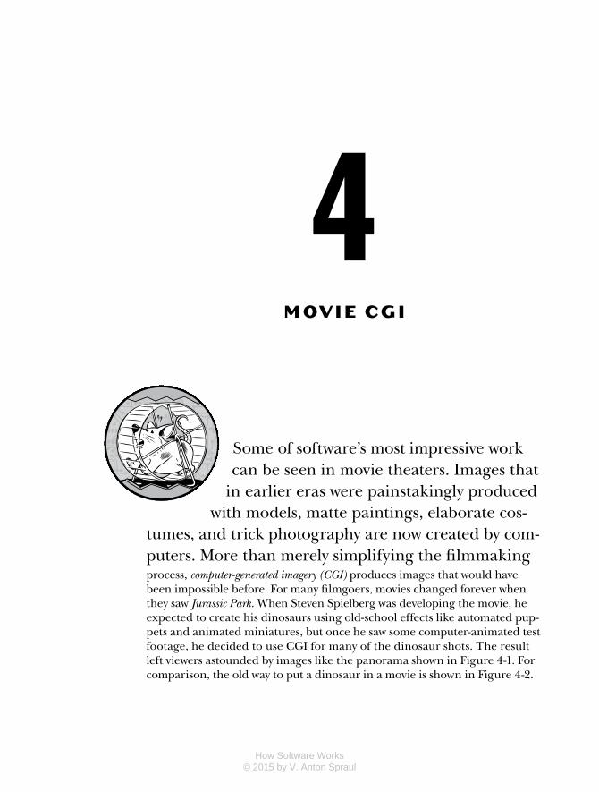
4M O V I E C G I
Some of software’s most impressive work can be seen in movie theaters. Images that
in earlier eras were painstakingly produced with models, matte paintings, elaborate cos-
tumes, and trick photography are now created by com-puters. More than merely simplifying the filmmakingprocess, computer-generated imagery (CGI) produces images that would have been impossible before. For many filmgoers, movies changed forever when they saw Jurassic Park. When Steven Spielberg was developing the movie, he expected to create his dinosaurs using old-school effects like automated pup-pets and animated miniatures, but once he saw some computer-animated test footage, he decided to use CGI for many of the dinosaur shots. The result left viewers astounded by images like the panorama shown in Figure 4-1. For comparison, the old way to put a dinosaur in a movie is shown in Figure 4-2.
How Software Works © 2015 by V. Anton Spraul

58 Chapter 4
Figure 4-1: CGI dinosaurs visit the watering hole in Jurassic Park (Universal Pictures/Amblin Entertainment, 1993).
Figure 4-2: The Beast from 20,000 Fathoms (Jack Dietz Productions, 1953) munches on Coney Island.
Amazing as they were, films like Jurassic Park were just the beginning of the CGI revolution. Now movies like Avatar create whole worlds using CGI, so that viewers are never sure what parts of a shot are physically real, if any. With enough time and money, it seems like filmmakers can produce any-thing imaginable.
How Software Works © 2015 by V. Anton Spraul

Movie CGI 59
Before computers blew our minds with dinosaurs and lush alien planets, though, they were transforming the world of traditionally animated movies. Using computers not only radically altered the process of traditional anima-tion, but as you’ll discover, the concepts and techniques employed are the foundation for almost everything in computer graphics. This is where the story of CGI begins.
Software for Traditional AnimationA movie is a series of still images, or frames, presented to the eye in rapid succession, like a high-speed slideshow. Each frame lingers on the retina for a moment after it disappears from the screen, effectively blending with the next frame to provide the illusion of continuous motion—a phenomenon known as persistence of vision. Traditionally, movies are shown at a rate of 24 frames per second (fps). Making a movie means producing 24 images for every second of the film.
A live-action movie uses a camera to collect images in real time. A tra-ditionally animated film like Lady and the Tramp, though, is created a bit differently: each frame of the movie is an individually photographed, hand-crafted work of art.
Traditional animation is a huge undertaking requiring a large team of artists. Typically, each character in an animated film is assigned a lead animator, but the lead animator does not draw the character on every frame in which he or she appears, because that’s too much work for one person. Instead, the lead animator draws only as many keyframes as are needed to suggest the action—perhaps one out of every few dozen frames of a finished animation sequence. Other animators draw the in-between frames to com-plete the sequence, a process known as tweening. At this stage, the animation is still just a series of pencil drawings on paper. The drawings must be trans-ferred to transparent cellulose sheets, which is why this style of animation is also known as cel animation. Then comes what animators call “ink and paint”: the faint pencil lines are traced over with black ink, and the cel is colored. Then the sheets are placed in front of a separately painted back-ground and photographed.
As you might expect, tweening, inking, and painting are tedious, time-intensive jobs. Beginning around 1990, computer imagery has been used to mimic the cel animation style with far less manual labor.
How Digital Images WorkIn a traditional animated film, each frame is a photograph of physical art, but computer animation works with digital images—pictures defined by numerical data.
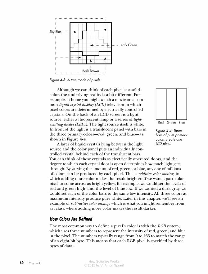
When you look at a video display such as a television, a smartphone screen, or a digitally projected theater screen, the image that reaches your eyes is made up of dots of varying colors, known as pixels. Figure 4-3 depicts a tree against a blue sky as a grid of pixels. Each of the 100 pixels in this 10×10 grid is assigned a color, here specified by name.
How Software Works © 2015 by V. Anton Spraul
60 Chapter 4
Leafy Green
Sky Blue
Bark Brown
Figure 4-3: A tree made of pixels
Although we can think of each pixel as a solid color, the underlying reality is a bit different. For example, at home you might watch a movie on a com-mon liquid crystal display (LCD) television in which pixel colors are determined by electrically controlled crystals. On the back of an LCD screen is a light source, either a fluorescent lamp or a series of light-emitting diodes (LEDs). The light source itself is white. In front of the light is a translucent panel with bars in the three primary colors—red, green, and blue—as shown in Figure 4-4.
A layer of liquid crystals lying between the light source and the color panel puts an individually con-trolled crystal behind each of the translucent bars. You can think of these crystals as electrically operated doors, and the degree to which each crystal door is open determines how much light gets through. By varying the amount of red, green, or blue, any one of millions of colors can be produced by each pixel. This is additive color mixing, in which adding more color makes the result brighter. If we want a particular pixel to come across as bright yellow, for example, we would set the levels of red and green high, and the level of blue low. If we wanted a dark gray, we would set each of the color bars to the same low intensity. All three colors at maximum intensity produce pure white. Later in this chapter, we’ll see an example of subtractive color mixing, which is what you might remember from art class, where adding more color makes the result darker.
How Colors Are DefinedThe most common way to define a pixel’s color is with the RGB system, which uses three numbers to represent the intensity of red, green, and blue in the pixel. The numbers typically range from 0 to 255 to match the range of an eight-bit byte. This means that each RGB pixel is specified by three bytes of data.
Red Green Blue
Figure 4-4: Three bars of pure primary colors create one LCD pixel.
How Software Works © 2015 by V. Anton Spraul
Movie CGI 61
As far as software is concerned, a digital image such as that shown in Figure 4-3 is just a list of bytes of color data, three bytes for each pixel. This block of bytes is known as the image’s bitmap. The first three bytes in the bitmap are the red, green, and blue levels of the pixel in the upper-left cor-ner of the image, and so on. The width and height of an image or bitmap in pixels is known as its resolution; for instance, Figure 4-3’s resolution is 10×10. A bitmap called a display buffer stores the colors of each pixel of a digital display like an LCD television; ultimately, computer graphics methods are about setting the numbers in a display buffer.
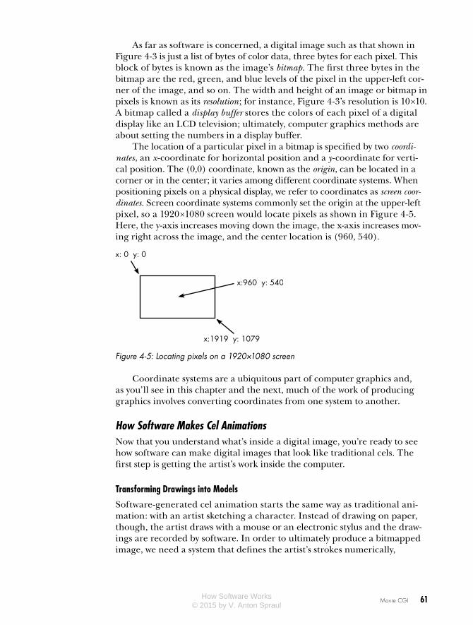
The location of a particular pixel in a bitmap is specified by two coordi-nates, an x-coordinate for horizontal position and a y -coordinate for verti-cal position. The (0,0) coordinate, known as the origin, can be located in a corner or in the center; it varies among different coordinate systems. When positioning pixels on a physical display, we refer to coordinates as screen coor-dinates. Screen coordinate systems commonly set the origin at the upper-left pixel, so a 1920×1080 screen would locate pixels as shown in Figure 4-5. Here, the y-axis increases moving down the image, the x-axis increases mov-ing right across the image, and the center location is (960, 540).
x: 0 y: 0
x:1919 y: 1079
x:960 y: 540
Figure 4-5: Locating pixels on a 1920×1080 screen
Coordinate systems are a ubiquitous part of computer graphics and, as you’ll see in this chapter and the next, much of the work of producing graphics involves converting coordinates from one system to another.
How Software Makes Cel AnimationsNow that you understand what’s inside a digital image, you’re ready to see how software can make digital images that look like traditional cels. The first step is getting the artist’s work inside the computer.
Transforming Drawings into Models
Software-generated cel animation starts the same way as traditional ani-mation: with an artist sketching a character. Instead of drawing on paper, though, the artist draws with a mouse or an electronic stylus and the draw-ings are recorded by software. In order to ultimately produce a bitmapped image, we need a system that defines the artist’s strokes numerically,
How Software Works © 2015 by V. Anton Spraul
62 Chapter 4
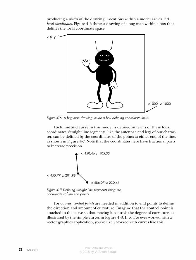
producing a model of the drawing. Locations within a model are called local coordinates. Figure 4-6 shows a drawing of a bug-man within a box that defines the local coordinate space.
x: 0 y: 0
x:1000 y: 1000
Figure 4-6: A bug-man drawing inside a box defining coordinate limits
Each line and curve in this model is defined in terms of these local coordinates. Straight line segments, like the antennae and legs of our charac-ter, can be defined by the coordinates of the points at either end of the line, as shown in Figure 4-7. Note that the coordinates here have fractional parts to increase precision.
x: 450.46 y: 105.33
x: 455.77 y: 201.98
x: 486.07 y: 230.46
Figure 4-7: Defining straight line segments using the coordinates of the end points
For curves, control points are needed in addition to end points to define the direction and amount of curvature. Imagine that the control point is attached to the curve so that moving it controls the degree of curvature, as illustrated by the simple curves in Figure 4-8. If you’ve ever worked with a vector graphics application, you’ve likely worked with curves like this.
How Software Works © 2015 by V. Anton Spraul

Movie CGI 63
Figure 4-8: Curves defined by two end points and one control point
Simple curves can be represented by just two end points and one control point, but longer, more complicated curves are made up of sequences of simple curves, as shown with the bug-man’s shoe in Figure 4-9.
The lines and curves define just the outline of a character or other drawing; the colors inside the outline are defined using a system such as RGB. The character model, then, is a numerical representation of all the lines, curves, and color data.
Automatic Tweening
Numerically defining drawings allows for automatic tweening. The animator draws one frame of a character’s animation sequence, then creates succeed-ing keyframes by moving the control points of the curves in the previous frames. The animation software can then generate the other frames through interpolation. The concept is demonstrated in Figure 4-10. Here, the coor-dinates of the middle point are calculated as the average of the coordinates of the other points. The x-coordinate of the interpolated point, 20, is halfway between 10 and 30; the y-coordinate, 120, is halfway between 100 and 140. In this example, all the points lie on a line, but the interpolation path can be a curve as well.
Keyframe 1 Point (10,100)
Keyframe 2 Point (30,140)
Interpolated Point (20,120)
Figure 4-10: Computing a middle point between two keyframe points via interpolation
Figure 4-9: A complicated curve made of simple curves
How Software Works © 2015 by V. Anton Spraul

64 Chapter 4
Figure 4-11 shows how interpolation creates new frames of animation. The leftmost face is the original model; the second face shows some of the control points; and the third has a wide mouth created by repositioning two of the control points downward. The rightmost face was created through linear interpolation, placing each control point halfway between the two keyframe positions. Animation software can create as many in-between positions as necessary to fill the gap between keyframes.
Figure 4-11: From left: a model, the model with selected control points, the model with two of the control points moved, and a tweened model created by interpolation between the positions of the previous two models
Although basic interpolation tweening can be a huge time-saver, adjust-ing the positions of lots of little points remains tedious. More advanced animation software can treat a character drawing as a complete, intercon-nected body, in which rigid connections and joints are specified. This means that an animator need only position the feet for each keyframe to make our bug-man walk, and the software positions the rest of the legs accordingly. The software might even handle real-world physics, so that a sequence of images of our bug-man falling over a log could be animated entirely by the software.
Positioning and Scaling
Numerical modeling also allows the drawings to be placed anywhere in a frame at any size. Changing the size of a model is called scaling, and is accomplished by multiplying or dividing the coordinates for each of the points. Figure 4-12 shows the bug-man model of Figure 4-6 scaled down to a quarter of its original area by dividing each of the coordinates in half. One point on his antenna is highlighted to show the idea.
Placing a model in a particular location on the screen is called transla-tion, and is accomplished by increasing or decreasing coordinates by fixed amounts. In Figure 4-13, the shrunken bug-man from Figure 4-12 is trans-lated to the middle of the screen by adding 700 to each x-coordinate and 200 to each y-coordinate.
How Software Works © 2015 by V. Anton Spraul

Movie CGI 65
Local 0,0
Local 1000,1000
Local 580,210
Local 0,0
Local 500,500
Local 290,105
Original Model Scaled-Down Model
Figure 4-12: Scaling a model means multiplying or dividing each of the coordinates.
Screen 0,0
Screen 1919,1079
Local 0,0Screen 700,200
Local 500,500Screen 1200,700
Local 290,105Screen 990,305
Figure 4-13: Translating a model means adding to or subtracting from coordinates.
“Ink and Paint” for Digital Images
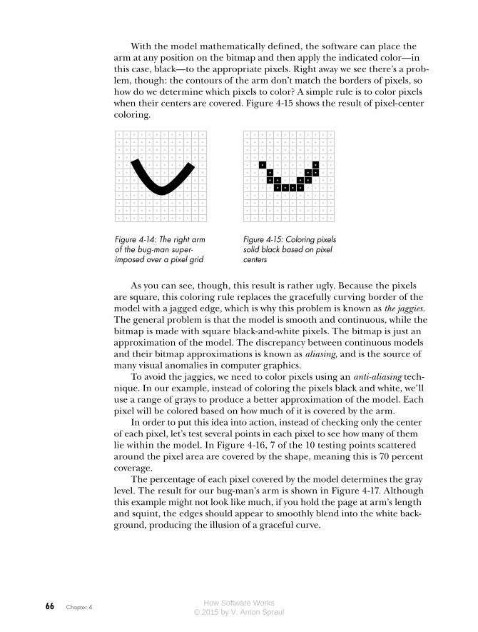
Now that the points on the models are mapped to screen coordinates, it’s time to transform each frame into a bitmap. This is the software version of cel animation’s “ink and paint.” To keep things simple, let’s look at how just the right arm of our bug-man model would be converted to a bitmap, or rasterized, when displayed over a solid white background. Figure 4-14 shows the arm over a pixel grid, with circles marking the pixel centers.
How Software Works © 2015 by V. Anton Spraul
66 Chapter 4
With the model mathematically defined, the software can place the arm at any position on the bitmap and then apply the indicated color—in this case, black—to the appropriate pixels. Right away we see there’s a prob-lem, though: the contours of the arm don’t match the borders of pixels, so how do we determine which pixels to color? A simple rule is to color pixels when their centers are covered. Figure 4-15 shows the result of pixel-center coloring.
As you can see, though, this result is rather ugly. Because the pixels are square, this coloring rule replaces the gracefully curving border of the model with a jagged edge, which is why this problem is known as the jaggies. The general problem is that the model is smooth and continuous, while the bitmap is made with square black-and-white pixels. The bitmap is just an approximation of the model. The discrepancy between continuous models and their bitmap approximations is known as aliasing, and is the source of many visual anomalies in computer graphics.
To avoid the jaggies, we need to color pixels using an anti-aliasing tech-nique. In our example, instead of coloring the pixels black and white, we’ll use a range of grays to produce a better approximation of the model. Each pixel will be colored based on how much of it is covered by the arm.
In order to put this idea into action, instead of checking only the center of each pixel, let’s test several points in each pixel to see how many of them lie within the model. In Figure 4-16, 7 of the 10 testing points scattered around the pixel area are covered by the shape, meaning this is 70 percent coverage.
The percentage of each pixel covered by the model determines the gray level. The result for our bug-man’s arm is shown in Figure 4-17. Although this example might not look like much, if you hold the page at arm’s length and squint, the edges should appear to smoothly blend into the white back-ground, producing the illusion of a graceful curve.
Figure 4-15: Coloring pixels solid black based on pixel centers
Figure 4-14: The right arm of the bug-man super-imposed over a pixel grid
How Software Works © 2015 by V. Anton Spraul

Movie CGI 67
Blending into Any Background
We need to generalize the technique just described in order for it to work with a background other than solid white. Consider Figure 4-18. On the left is the bug-man model, and in the middle is the background for the shot in which he’ll appear: a close-up of a setting sun over a rocky terrain. On the right is the complete image with the model superimposed over the background.
Model Background Model over Background
Figure 4-18: The bug-man model, a background, and the model superimposed over the background
This book is printed in black and white, but in this image the sun would be shades of reddish-orange and the ground would be shades of brown. As before, pixels along the model’s edge will appear jagged unless we use an anti-aliasing technique. But using the previous technique to color pixels in gray tones won’t help the black edge blend into a background of red-orange and brown pixels.
A more general anti-aliasing technique calculates an alpha level for each pixel based on the percentage of the pixel that’s covered by the model. You can think of an alpha level as a measure of opacity. Like the color levels, an alpha level is typically defined in the range of 0–255. In Figure 4-19, a black
With the model mathematically defined, the software can place the arm at any position on the bitmap and then apply the indicated color—in this case, black—to the appropriate pixels. Right away we see there’s a prob-lem, though: the contours of the arm don’t match the borders of pixels, so how do we determine which pixels to color? A simple rule is to color pixels when their centers are covered. Figure 4-15 shows the result of pixel-center coloring.
As you can see, though, this result is rather ugly. Because the pixels are square, this coloring rule replaces the gracefully curving border of the model with a jagged edge, which is why this problem is known as the jaggies. The general problem is that the model is smooth and continuous, while the bitmap is made with square black-and-white pixels. The bitmap is just an approximation of the model. The discrepancy between continuous models and their bitmap approximations is known as aliasing, and is the source of many visual anomalies in computer graphics.
To avoid the jaggies, we need to color pixels using an anti-aliasing tech-nique. In our example, instead of coloring the pixels black and white, we’ll use a range of grays to produce a better approximation of the model. Each pixel will be colored based on how much of it is covered by the arm.
In order to put this idea into action, instead of checking only the center of each pixel, let’s test several points in each pixel to see how many of them lie within the model. In Figure 4-16, 7 of the 10 testing points scattered around the pixel area are covered by the shape, meaning this is 70 percent coverage.
The percentage of each pixel covered by the model determines the gray level. The result for our bug-man’s arm is shown in Figure 4-17. Although this example might not look like much, if you hold the page at arm’s length and squint, the edges should appear to smoothly blend into the white back-ground, producing the illusion of a graceful curve.
Figure 4-16: A close-up of one pixel at the end of the bug-man’s arm, with a scattering of 10 points to estimate the area cov-ered by the model
Figure 4-17: Using grayscale to anti-alias, shown with and without the pixel grid.
How Software Works © 2015 by V. Anton Spraul

68 Chapter 4
bar is superimposed over a tree at different alpha levels. At an alpha level of 255, the bar is entirely opaque, while at 25 the bar is barely visible. An alpha level of 0 would make the bar completely invisible.
The alpha levels of all the pixels in a bitmap are collectively referred to as its alpha channel. The process of making an alpha channel for a model is similar to how we anti-aliased the black arm against the white background, only rather than assigning a shade of gray based on the pixel’s coverage percentage, we assign an alpha value for the pixel instead. Each model is thus conceptually transformed into both a bitmap, showing the color of each pixel covered by the model, and an alpha channel, showing the opacity of each pixel. Figure 4-20 shows the color bitmap (here, just black pixels) and the alpha channel of the bug-man arm separately.
Model Color Bitmap Alpha Channel
Figure 4-20: The arm of the bug-man model with its corresponding color bitmap and alpha channel
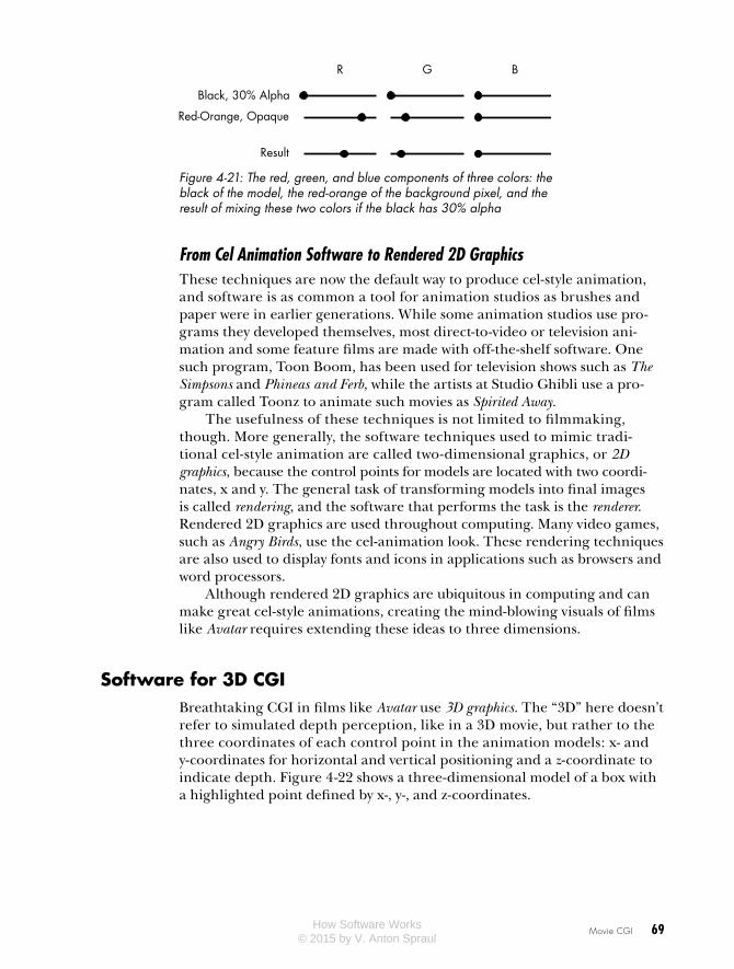
Now the model can be applied to any background. The final color of each pixel is a blend of the color in the background and the model’s color bitmap, with the alpha level determining how much of each color goes into the mix. In the bug-man scene of Figure 4-18, if a black bug-man pixel with 30 percent alpha were placed on top of a red-orange sunset background pixel, the result would be a darker red-orange, as shown in Figure 4-21. The resulting amount of each color component lies somewhere between the two mixed colors, but because the black pixel is only 30 percent alpha, the red-orange background color dominates. For pixels completely covered by the model, the alpha level is 100 percent and the color in the final image is the same as in the model’s color bitmap. In this way, a bitmap with an alpha channel can be smoothly blended into any background.
57 55200252125
Figure 4-19: A tree covered by five black bars of varying alpha level
How Software Works © 2015 by V. Anton Spraul
Movie CGI 69
R G B
Black, 30% Alpha
Red-Orange, Opaque
Result
Figure 4-21: The red, green, and blue components of three colors: the black of the model, the red-orange of the background pixel, and the result of mixing these two colors if the black has 30% alpha
From Cel Animation Software to Rendered 2D Graphics These techniques are now the default way to produce cel-style animation, and software is as common a tool for animation studios as brushes and paper were in earlier generations. While some animation studios use pro-grams they developed themselves, most direct-to-video or television ani-mation and some feature films are made with off-the-shelf software. One such program, Toon Boom, has been used for television shows such as The Simpsons and Phineas and Ferb, while the artists at Studio Ghibli use a pro-gram called Toonz to animate such movies as Spirited Away.
The usefulness of these techniques is not limited to filmmaking, though. More generally, the software techniques used to mimic tradi-tional cel-style animation are called two-dimensional graphics, or 2D graphics, because the control points for models are located with two coordi-nates, x and y. The general task of transforming models into final images is called rendering, and the software that performs the task is the renderer. Rendered 2D graphics are used throughout computing. Many video games, such as Angry Birds, use the cel-animation look. These rendering techniques are also used to display fonts and icons in applications such as browsers and word processors.
Although rendered 2D graphics are ubiquitous in computing and can make great cel-style animations, creating the mind-blowing visuals of films like Avatar requires extending these ideas to three dimensions.
Software for 3D CGIBreathtaking CGI in films like Avatar use 3D graphics. The “3D” here doesn’t refer to simulated depth perception, like in a 3D movie, but rather to the three coordinates of each control point in the animation models: x- and y-coordinates for horizontal and vertical positioning and a z-coordinate to indicate depth. Figure 4-22 shows a three-dimensional model of a box with a highlighted point defined by x-, y-, and z-coordinates.
How Software Works © 2015 by V. Anton Spraul

70 Chapter 4
–z
–x
–y
x: 100y: 0z: –100
+x
+y
+z
Figure 4-22: A box in three-dimensional space
As with 2D graphics, 3D graphics are all about rendering models into bitmaps. The rendering methods that produce the most realistic results require the most processing time. Movie CGI is impressive largely because the renderer can process each frame for a very long time, resulting in the high-quality result that I’ll call movie-quality rendering. We’ll discuss the keys to movie-quality rendering in this chapter. Then, in Chapter 5, we’ll talk about graphics for video games, and see how many of the techniques shown here have to be modified, faked, or scrapped altogether when images must be produced in real time in response to user interaction.
How 3D Scenes Are Described3D models are built out of lines and curves just like 2D models, but these lines and curves stretch across three dimensions instead of two. The box in Figure 4-22 is a very simple model defined by eight points; the models used in movie CGI tend to be complex, defined by hundreds, thousands, or even tens of thousands of points. As with 2D rendering, models in 3D rendering are defined by local coordinates. The points at the corners of the box in Figure 4-22, for example, are defined relative to the local origin at the bot-tom of the box.
While 2D rendering can directly map from local coordinates to screen coordinates, 3D models are first placed into scenes in a virtual world that has its own coordinate space called world coordinates. Designing a 3D scene is the CGI equivalent of building a movie set. We can place as many models as we want in the virtual world, of any size and at any location, and the renderer can figure out the world coordinates for all the locations on the models.
Introducing another coordinate system might seem like an unnecessary complication, but world coordinates actually make 3D graphics much easier in the long run. For example, an artist can model a dining room chair inde-pendently of the other models for the scene in which it will be used. Then the artist can copy the single chair model to make as many seats as needed
How Software Works © 2015 by V. Anton Spraul

Movie CGI 71
for the dining room scene. Also, a scene, like a movie set, isn’t built to pro-duce a single image but to create a space that will be shown in many images from many different angles, as we’ll see in the next section.
The Virtual CameraWith the scenery in place, a viewpoint is needed. On a movie set, a cine-ma tographer determines what image is captured by placing the camera and choosing a lens. For CGI, the viewpoint determines how the three-dimensional scene is transformed into a two-dimensional rendered image.
Transformation from three dimensions to two is known as projection. To better understand projection, consider Figure 4-23, in which an imaginary pyramid originates from the eye of a viewer looking at a table. A translu-cent grid lies in the pyramid between the viewer and the scene. Looking through the grid, the viewer can map each visible location on the three-dimensional table to a particular square on the two-dimensional grid. That’s projection, but instead of a grid of squares, it’s a grid of pixels in a bitmap.
Figure 4-23: Projecting a three-dimensional scene onto a flat display is like viewing a real-world scene through a translucent grid.
Direct LightingThere are many different methods of projection, but projection methods in movie-quality rendering are part of the larger issue of lighting. Although we don’t often realize it, our perception of an object’s color is determined
How Software Works © 2015 by V. Anton Spraul
72 Chapter 4
not only by the object itself but also by the lighting under which we view the object. Knowing this, filmmakers carefully light their scenes for dramatic effect, but the problem of lighting in CGI is more fundamental. Without an accurate model of scene lighting, the resulting images won’t look realistic at all.
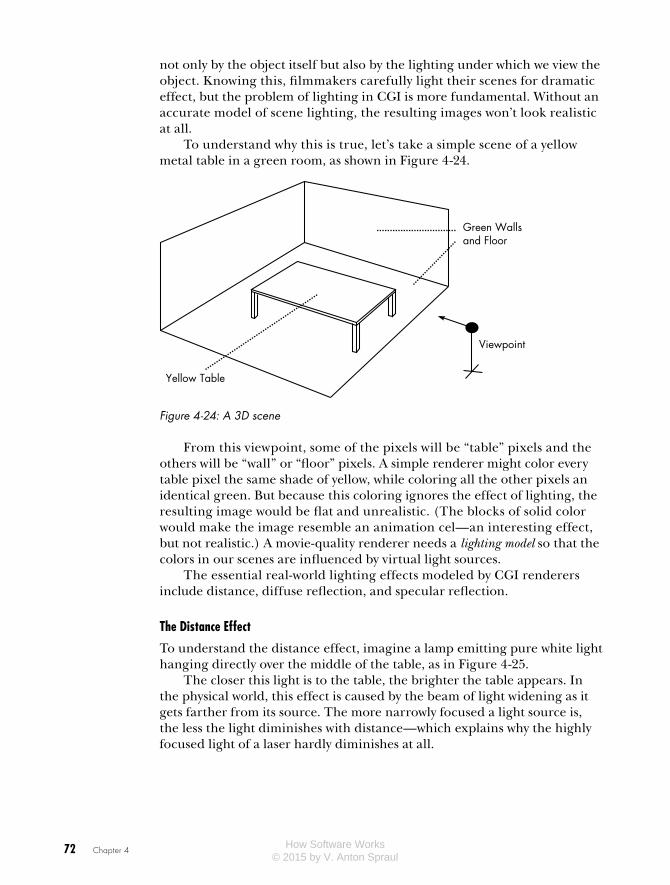
To understand why this is true, let’s take a simple scene of a yellow metal table in a green room, as shown in Figure 4-24.
Yellow Table
Green Wallsand Floor
Viewpoint
Figure 4-24: A 3D scene
From this viewpoint, some of the pixels will be “table” pixels and the others will be “wall” or “floor” pixels. A simple renderer might color every table pixel the same shade of yellow, while coloring all the other pixels an identical green. But because this coloring ignores the effect of lighting, the resulting image would be flat and unrealistic. (The blocks of solid color would make the image resemble an animation cel—an interesting effect, but not realistic.) A movie-quality renderer needs a lighting model so that the colors in our scenes are influenced by virtual light sources.
The essential real-world lighting effects modeled by CGI renderers include distance, diffuse reflection, and specular reflection.
The Distance Effect
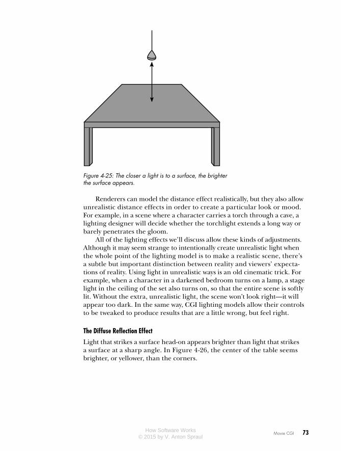
To understand the distance effect, imagine a lamp emitting pure white light hanging directly over the middle of the table, as in Figure 4-25.
The closer this light is to the table, the brighter the table appears. In the physical world, this effect is caused by the beam of light widening as it gets farther from its source. The more narrowly focused a light source is, the less the light diminishes with distance—which explains why the highly focused light of a laser hardly diminishes at all.
How Software Works © 2015 by V. Anton Spraul
Movie CGI 73
Figure 4-25: The closer a light is to a surface, the brighter the surface appears.
Renderers can model the distance effect realistically, but they also allow unrealistic distance effects in order to create a particular look or mood. For example, in a scene where a character carries a torch through a cave, a lighting designer will decide whether the torchlight extends a long way or barely penetrates the gloom.
All of the lighting effects we’ll discuss allow these kinds of adjustments. Although it may seem strange to intentionally create unrealistic light when the whole point of the lighting model is to make a realistic scene, there’s a subtle but important distinction between reality and viewers’ expecta-tions of reality. Using light in unrealistic ways is an old cinematic trick. For example, when a character in a darkened bedroom turns on a lamp, a stage light in the ceiling of the set also turns on, so that the entire scene is softly lit. Without the extra, unrealistic light, the scene won’t look right—it will appear too dark. In the same way, CGI lighting models allow their controls to be tweaked to produce results that are a little wrong, but feel right.
The Diffuse Reflection Effect
Light that strikes a surface head-on appears brighter than light that strikes a surface at a sharp angle. In Figure 4-26, the center of the table seems brighter, or yellower, than the corners.
How Software Works © 2015 by V. Anton Spraul

74 Chapter 4
Figure 4-26: Diffuse lighting depends on the angle at which light strikes a surface.
This is due in part to the distance effect—the center is closer to the lamp than the corners—but is mostly due to the diffuse reflection effect, a change in brightness caused by variation in the light’s angle of incidence. In Figure 4-27, the solid lines show the incident light rays, while the dashed lines are reflections. As you can see, the light strikes point B at a much larger angle than at point A, and therefore point B appears brighter than point A. But note that the viewing angle, or angle of ref lectance, makes no difference in the diffuse reflection effect. Therefore, point A will look the same to both viewers, and so will point B.
A B
Angles of Incidence
Figure 4-27: Diffuse lighting varies based on the angle at which the light strikes the surface, but is the same for all viewpoints.
How Software Works © 2015 by V. Anton Spraul

Movie CGI 75
The Specular Reflection Effect
Because the metal tabletop is highly reflective, it partially acts as a mir-ror. As with any mirror, what you see in it depends on what lies on the opposite angle to your point of view. Figure 4-28 shows a shiny spot on the table where the hanging light is at the opposite angle from our viewpoint, approximately midway between the center of the table and the closest edge. Because this spot is a mirror-like reflection of the white light bulb, the spot will be white.
Figure 4-28: Specular lighting depends on both the angle at which the light strikes the surface and the view angle.
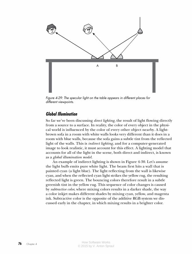
These shiny spots are known as specular reflections, and appear where the light’s angle of incidence matches the angle of reflectance. Figure 4-29 shows the location of specular reflections for two different viewpoints; notice that each ray rebounds at the same angle that it struck the table. Both viewers see a shiny spot on the table, but they see the spot in different places.
In the real world, some materials reflect differently than others. A shiny material like plastic has a high level of specular reflection, while a dull material like cotton cloth has more diffuse reflection. CGI lighting models allow artists to set different reflection properties for each surface on a model to match the appearance of real-world materials.
How Software Works © 2015 by V. Anton Spraul
76 Chapter 4
A B
Figure 4-29: The specular light on the table appears in different places for different viewpoints.
Global IlluminationSo far we’ve been discussing direct lighting, the result of light flowing directly from a source to a surface. In reality, the color of every object in the physi-cal world is influenced by the color of every other object nearby. A light-brown sofa in a room with white walls looks very different than it does in a room with blue walls, because the sofa gains a subtle tint from the reflected light of the walls. This is indirect lighting, and for a computer-generated image to look realistic, it must account for this effect. A lighting model that accounts for all of the light in the scene, both direct and indirect, is known as a global illumination model.
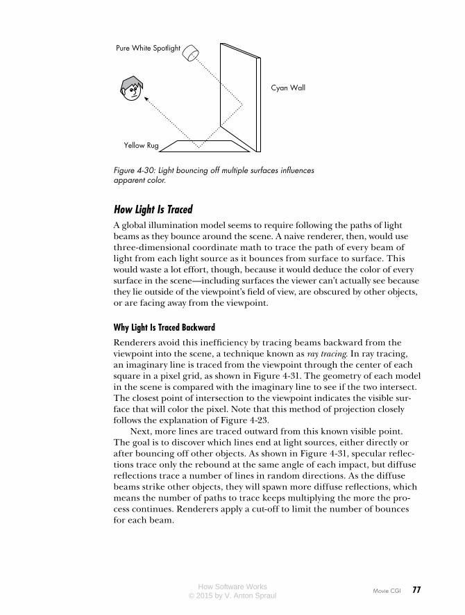
An example of indirect lighting is shown in Figure 4-30. Let’s assume the light bulb emits pure white light. The beam first hits a wall that is painted cyan (a light blue). The light reflecting from the wall is likewise cyan, and when the reflected cyan light strikes the yellow rug, the resulting reflected light is green. The bouncing colors therefore result in a subtle greenish tint in the yellow rug. This sequence of color changes is caused by subtractive color, where mixing colors results in a darker shade, the way a color inkjet makes different shades by mixing cyan, yellow, and magenta ink. Subtractive color is the opposite of the additive RGB system we dis-cussed early in the chapter, in which mixing results in a brighter color.
How Software Works © 2015 by V. Anton Spraul
Movie CGI 77
Cyan Wall
Yellow Rug
Pure White Spotlight
Figure 4-30: Light bouncing off multiple surfaces influences apparent color.
How Light Is TracedA global illumination model seems to require following the paths of light beams as they bounce around the scene. A naive renderer, then, would use three-dimensional coordinate math to trace the path of every beam of light from each light source as it bounces from surface to surface. This would waste a lot effort, though, because it would deduce the color of every surface in the scene—including surfaces the viewer can’t actually see because they lie outside of the viewpoint’s field of view, are obscured by other objects, or are facing away from the viewpoint.
Why Light Is Traced Backward
Renderers avoid this inefficiency by tracing beams backward from the viewpoint into the scene, a technique known as ray tracing. In ray tracing, an imaginary line is traced from the viewpoint through the center of each square in a pixel grid, as shown in Figure 4-31. The geometry of each model in the scene is compared with the imaginary line to see if the two intersect. The closest point of intersection to the viewpoint indicates the visible sur-face that will color the pixel. Note that this method of projection closely follows the explanation of Figure 4-23.
Next, more lines are traced outward from this known visible point. The goal is to discover which lines end at light sources, either directly or after bouncing off other objects. As shown in Figure 4-31, specular reflec-tions trace only the rebound at the same angle of each impact, but diffuse reflections trace a number of lines in random directions. As the diffuse beams strike other objects, they will spawn more diffuse reflections, which means the number of paths to trace keeps multiplying the more the pro-cess continues. Renderers apply a cut-off to limit the number of bounces for each beam.
How Software Works © 2015 by V. Anton Spraul

78 Chapter 4
Specular
Diffuse
Figure 4-31: Tracing a beam of light from a viewpoint, through the center of the shaded pixel, until it reaches a model in the scene. To determine specular lighting, the tracing rebounds at the same angle as impact; for diffuse lighting, it rebounds at several random angles.
How Ray Tracing Models Real-World Effects
Although ray tracing is a lot of work for even a network of computers, the method can accurately model many real-world visual effects.
One such effect is translucency. Although a bitmap can be made trans-lucent by assigning low alpha values to pixels, that’s not the whole story for transparent materials like glass. A glass tumbler, for example, doesn’t merely allow light to pass through it, but also distorts whatever is behind it, as shown in Figure 4-32.
Figure 4-32: The distortion of curved glass
How Software Works © 2015 by V. Anton Spraul
Movie CGI 79
A ray tracing renderer can refract light beams according to the laws of optics as they pass through translucent materials. This will not only allow the renderer to model glass in CGI, but will also help to reproduce the dis-torting effects of transparent materials and liquids like water.
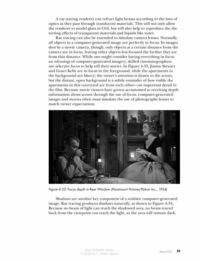
Ray tracing can also be extended to simulate camera lenses. Normally, all objects in a computer-generated image are perfectly in focus. In images shot by a movie camera, though, only objects at a certain distance from the camera are in focus, leaving other objects less focused the farther they are from that distance. While one might consider having everything in focus an advantage of computer-generated imagery, skilled cinematographers use selective focus to help tell their stories. In Figure 4-33, Jimmy Stewart and Grace Kelly are in focus in the foreground, while the apartments in the background are blurry; the viewer’s attention is drawn to the actors, but the distant, open background is a subtle reminder of how visible the apartments in this courtyard are from each other—an important detail in the film. Because movie viewers have grown accustomed to receiving depth information about scenes through the use of focus, computer-generated images and movies often must simulate the use of photography lenses to match viewer expectations.
Figure 4-33: Focus depth in Rear Window (Paramount Pictures/Patron Inc., 1954)
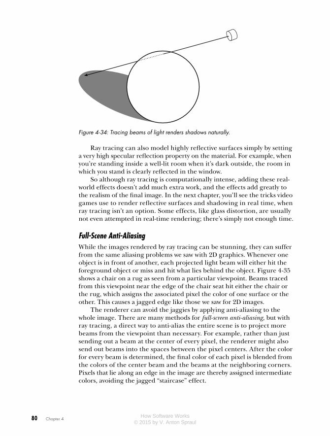
Shadows are another key component of a realistic computer-generated image. Ray tracing produces shadows naturally, as shown in Figure 4-34. Because no beam of light can reach the shadowed area, no beam traced back from the viewpoint can reach the light, so the area will remain dark.
How Software Works © 2015 by V. Anton Spraul
80 Chapter 4
Figure 4-34: Tracing beams of light renders shadows naturally.
Ray tracing can also model highly reflective surfaces simply by setting a very high specular reflection property on the material. For example, when you’re standing inside a well-lit room when it’s dark outside, the room in which you stand is clearly reflected in the window.
So although ray tracing is computationally intense, adding these real-world effects doesn’t add much extra work, and the effects add greatly to the realism of the final image. In the next chapter, you’ll see the tricks video games use to render reflective surfaces and shadowing in real time, when ray tracing isn’t an option. Some effects, like glass distortion, are usually not even attempted in real-time rendering; there’s simply not enough time.
Full-Scene Anti-AliasingWhile the images rendered by ray tracing can be stunning, they can suffer from the same aliasing problems we saw with 2D graphics. Whenever one object is in front of another, each projected light beam will either hit the foreground object or miss and hit what lies behind the object. Figure 4-35 shows a chair on a rug as seen from a particular viewpoint. Beams traced from this viewpoint near the edge of the chair seat hit either the chair or the rug, which assigns the associated pixel the color of one surface or the other. This causes a jagged edge like those we saw for 2D images.
The renderer can avoid the jaggies by applying anti-aliasing to the whole image. There are many methods for full-screen anti-aliasing, but with ray tracing, a direct way to anti-alias the entire scene is to project more beams from the viewpoint than necessary. For example, rather than just sending out a beam at the center of every pixel, the renderer might also send out beams into the spaces between the pixel centers. After the color for every beam is determined, the final color of each pixel is blended from the colors of the center beam and the beams at the neighboring corners. Pixels that lie along an edge in the image are thereby assigned intermediate colors, avoiding the jagged “staircase” effect.
How Software Works © 2015 by V. Anton Spraul

Movie CGI 81
Figure 4-35: In the highlighted area, each light beam trace ends on the chair or the rug, resulting in jaggies.
Figure 4-36 demonstrates this idea. Each circle represents a beam pro-jected into a scene. The pixels are colored based on the average of colors in the center and corners of each pixel, which results in the anti-aliased edge shown on the right. More beams can be traced for even better results, at the expense of more processing time.
Figure 4-36: Each pixel’s final color is a blend of five beams traced into the scene, one at the center of the pixel, and four at the corners.
Combining the Real and the FakeIn a completely computer-animated film, rendering is the final step in pro-ducing each frame, but when CGI is integrated into live-action films, there’s more work to be done. Imagine, for example, a scene in which a computer-generated Tyrannosaurus rex stalks through a real field of grass.
How Software Works © 2015 by V. Anton Spraul
82 Chapter 4
To make this happen, we first need two sequences of digital images. One sequence shows the grass field, and has either been shot on a digital camera or on a traditional film camera and then subsequently scanned. Either way, the movements of the camera are computer controlled, which allows the camera movement to match up precisely with the movement of the virtual camera in the other sequence, the computer-generated anima-tion of the dinosaur.
Next, the two sequences are combined, frame-by-frame, in a process called digital composition. Although the dinosaur sequence was produced from 3D models, at this point both sequences are simply two-dimensional bitmaps and are combined using the same method used to place our bug-man on top of the sunset back in Figure 4-18. Through the use of alpha blending, the edges of the dinosaur in each frame are smoothly blended with the field-of-grass background. Without this blending, the dinosaur will have a shimmering edge like that of a weatherman standing in front of the five-day forecast.
Digital composition is used throughout modern moviemaking, even when no computer-generated imagery is involved, such as for dissolves (a transition where one scene smoothly fades into the next). Formerly, dis-solves were produced by a device known as an optical printer, which pointed a camera at a screen onto which several projectors were aimed. The camera would make a new film that combined the images of the projected films. A dissolve was accomplished by turning down the light in one projector while turning up the light on another. The results were acceptable, but you could always spot an optical printer sequence in a movie because the second-generation images would be blurry compared to the rest of the film. Now, dissolves, superimposed titles, and all sorts of other movie effects that you might not really think of as “effects” are performed with digital composition.
The Ideal of Movie-Quality RenderingWhen all the advanced rendering techniques described in this chapter come together, the results can be stunningly realistic, highly stylized, or anything in between. The only real limitation on CGI is time, but that’s a big limitation. The truth is, what I’ve been calling movie-quality rendering can be an unattainable ideal even for Hollywood. Although films can be in production for several years, there’s only so much time that can be allot-ted for each frame. Consider the computer-animated Pixar film WALL-E. With a running time of 98 minutes, the film required the rendering of over 140,000 high-resolution computer images. If Pixar wanted to produce all of the images for WALL-E in two years, it would have to render images, on average, every eight minutes.
How Software Works © 2015 by V. Anton Spraul
Movie CGI 83
Even on a networked “render farm,” eight minutes is not sufficient to use ray tracing, global illumination, glass refraction, and all the other high-end techniques for every single image. Faced with these practical constraints, filmmakers pick and choose which techniques to use on each sequence to maximize visual impact. When ideal rendering is required, the time is spent, but when the best effects won’t be missed or the budget won’t allow it, they aren’t used. The renderer used at Pixar—a program called RenderMan that was originally developed at Lucasfilm—can forgo ray trac-ing and its massive associated computational effort, but that means many of the realism-enhancing effects have to be produced some other way.
But how is that done? What kinds of tricks are needed to render images without ray tracing—images that may not be perfectly realistic but are still amazing? To answer this question, we’ll turn from Hollywood to the world of video games, where rendering is under an extreme time limitation. How extreme? If eight minutes isn’t enough time to produce an ideal render, imagine trying to render an image in under 20 milliseconds. In the next chapter, we’ll see how video games produce great graphics in a hurry.
How Software Works © 2015 by V. Anton Spraul