Mounting systems for solar technology · Mounting systems for solar technology ASSEMBLY...
14
www.k2-systems.com Mounting systems for solar technology ASSEMBLY INSTRUCTIONS S-Dome small System
Transcript of Mounting systems for solar technology · Mounting systems for solar technology ASSEMBLY...

www.k2-systems.com
Mounting systems for solar technology
ASSEMBLY INSTRUCTIONS
S-Dome small System

2
QUALITY TESTED – SEVERAL CERTIFICATIONSK2 Systems stands for secure connections, highest quality andprecision. Our customers and business partners have known thatfor a long time. Independent institutes have tested, confi rmed andcertifi ed our capabilities and components.
Please fi nd our quality and product certifi cates under:www.k2-systems.com/en/technical-information
T Tools overview 3
T General safety informationTools overview 4
T The following guidelines apply 5
T Required Materials 6
T Assembly 8
T Notes 12
Content

3
Tools overview
6 mm6 - 30 Nm (4,5 - 22,2 lb-ft)
≥ 3,0 m ≥ 6,0 m
8 mm

4
General safety informationPlease note that our general mounting instructions must be followed at all times and can be viewedonline at www.k2-systems.com/en/technical-information.
T The equipment may only be installed and operated by qualified and adequately trained installers.
T Prior to installation, ensure that the product complies with on-site static loading requirements. For roof-mounted systems, the roof load-bearing capacity must always be checked.
T National and local building regulations and environmental requirements must be adhered to.
T Compliance with health and safety regulations, accident prevention guidelines and applicable standards is required. · Protective equipment such as safety helmet, boots and gloves must be worn. · Roofing works must be in accordance with roofing regulations utilising fall protection safeguards when eaves height exceeds 3 m.
· At least two people must be present for the duration of the installation work in order to provide rapid assistance in the event of an emergency.
T K2 mounting systems are continuously developed and improved and the installation process may thereby change at any time. Prior to installation consult our website at www.k2-systems.com/en/technical-information for up-to-date instructions. We can send you the latest version on request.
T The assembly instructions of the module manufacturer must be adhered to.
T Equipotential bonding/grounding/earthing between individual parts is to be performed according to country specific standards, as well as national laws and regulations.
T At least one copy of the assembly instructions should be available on site throughout the duration of the installation.
T Failure to adhere to our general safety and assembly instructions and not using all system components, K2 is not liable for any resulting defects or damages. We do not accept liability for any damage resulting in the use of competitor’s parts. Warranty is excluded in such cases.
T German law shall apply excluding the UN Convention on CISG. Place of venue is Stuttgart. Our General Terms of Business apply.
T If all safety instructions are adhered to and the system is correctly installed, there is a product warranty entitlement of 12 years! We strongly recommend reviewing our terms of guarantee, which can be viewed at www.k2-systems.com/en/technical-information We will also send this information on request.
T Dismantling of the system is performed in reverse order to the assembly.
T K2 stainless steel components are available in different corrosion resistance classes. Each structure or component must be carefully checked for possible corrosion exposure.

5
The following guidelines applyThe S-Dome small system can be used without further testing by K2 systems in the following stan-dard conditions. To calculate maximum distances between supports we recommend using our calcu-lation tool K2Base. The system is also suitable for higher requirements. However, if a value exceeds the standard conditions, please contact K2 Systems.
ROOF REQUIREMENTS
T Minimum trapezoidal sheet thickness of 0.5 mm (for steel S235 according to DIN EN 10025-1 and aluminium with a tensile strength of 195 N/mm²)
T Roof pitch of 0 - 15°
STATIC REQUIREMENTS
T The sufficient holding force of the roof covering at the support or substructure must be ensured on site.
T For framed modules with a frame height of 34 - 50 mm
IMPORTANT MOUNTING INSTRUCTIONS
T On-site general standards and regulations for lightning protection must be observed and consul-tation with a specialist to create a lightning protection concept is recommended (use lightning protection clamp if necessary).
T Ensure sufficient gap is left between the modules as specified by the module manufacturer, other-wise we recommend a 5 mm distance between modules.
T If the trapezoidal sheet is fastened with storm washers, please do not fasten the MultiRails on the storm washers! Spacing must be measured beforehand.
T The inclination of the Dome system is 10°.
T A minimum distance to the roof edge of 600 mm must be observed.
T The K2 Systems planning instructions in this document define the spacing you must leave between the module rows. Please adhere to this.
T Modules with a surface area of up to 2m2 and width ranging from and a width of 950 to 1050 mm can be used.
T Tightening torque for all module clamps 14 Nm
T For manufacturer information regarding clamps see the manufacturing module data sheet.

6
Essential: The materials requiredAll system components listed in the following are essential for assembling the K2 Systems S-Dome small system. The piece quantities are calculated on the basis of the respective requirements. The listed item numbers facilitate the comparison of items.
K2 Dome S1000 small
Width: 40 mmMaterial: Aluminium EN AW-6063 T66
Mounting Rail K2 MultiRail 25/4
Length: 250 mmMaterial: Aluminium EN AW-6063 T66, EPDM
| 2002793
K2 Dome SD small
Width: 40 mmMaterial: Aluminium EN AW-6063 T66
| 2000774
| 2000775
K2 FlexClamp small
Material: Aluminium, Stainless steel
| 2000773
K2 thread-forming tapping screw with mounted EPDM supported washerMaterial: Stainless steel A2, EPDM
| 1005207

7
MK2 Slot nut with clip Material: Stainless Steel, PA
| 1001643
K2 Allen bolt with serrated under head M8x20 according to DIN 912/ EN ISO 4762Material: stainless steel A2, WS 6 mm
| 2001729
8
Assembly
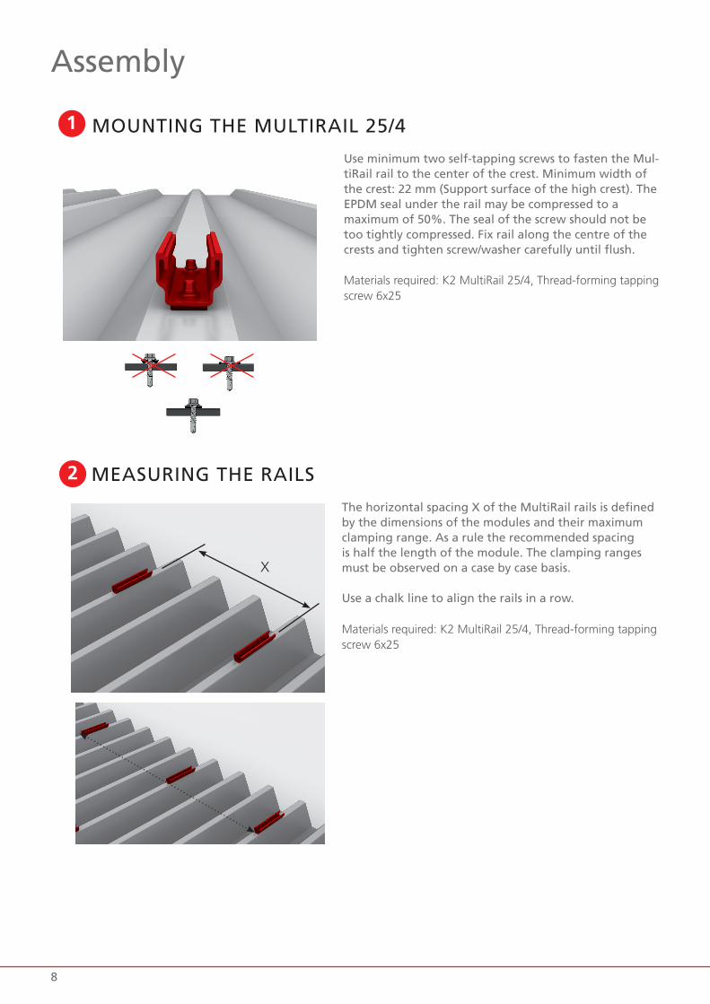
1 MOUNTING THE MULTIRAIL 25/4
Use minimum two self-tapping screws to fasten the Mul-tiRail rail to the center of the crest. Minimum width of the crest: 22 mm (Support surface of the high crest). The EPDM seal under the rail may be compressed to amaximum of 50%. The seal of the screw should not be too tightly compressed. Fix rail along the centre of the crests and tighten screw/washer carefully until flush.
Materials required: K2 MultiRail 25/4, Thread-forming tapping screw 6x25
2
The horizontal spacing X of the MultiRail rails is defined by the dimensions of the modules and their maximum clamping range. As a rule the recommended spacing is half the length of the module. The clamping ranges must be observed on a case by case basis.
Use a chalk line to align the rails in a row.
Materials required: K2 MultiRail 25/4, Thread-forming tapping screw 6x25
MEASURING THE RAILS
X

9
3 MEASURING AND FASTENING THE OTHER RAILS
The vertical distance Y between the MultiRails is 1.27 m.
Repeat steps 1 and 2 to assemble the other rows.
Materials required: K2 MultiRail 25/4, Thread-forming tapping screw 6x25
Y

10
Insert two M K2 slot nuts in the rail and turn 90° clock-wise until they lock. Then position the Dome S1000 small on the rail and fasten with two M8x20 Bolts with serrated under head.
Torque: 16 Nm
Materials required: Dome S1000 small, M K2 slot nut, M8x20 Bolts with serrated under head
4 ASSEMBLY DOME S1000 SMALL
Insert one M K2 slot nut in the rail and turn 90° clockwi-se until locked. Then position the Dome SD small on to the rail and secure hand tight with an M8x20 Bolts with serrated under head.
Materials required: Dome S1000 small, M K2 slot nut, M8x20 Bolts with serrated under head
5 ASSEMBLY DOME SD SMALL
Insert the pre-assembled middle piece of the FlexClamp set into the channels of the domes and secure by tigh-tening the bolt.
Torque: 14 Nm
Tip: For module mounting, it is helpful if only the FlexClamp small sets are completely pre-mounted on the Dome SD small.
Materials required: FlexClamp small Set
6 ASSEMBLY FLEXCLAMP SMALL

11
7 POSITIONING MODULES AND FASTENING DOME SD
First insert the module in horizontal position into the lower FlexClamp small of the Dome SD small as far as it will go. Then place the module on the upper FlexClamp small of the dome S1000 small and screw the upper part of the FlexClamp set onto the FlexClamp middle part and fix the module to the stop.
Torque: 14 Nm
Torque of the K2 Dome SD small on MultiRail: 16 Nm

12
Notes

13

Mounting systems for solar technology
K2 Systems GmbH
Industriestraße 18 71272 Renningen Germany
Tel. +49 (0) 7159 - 42059 - 0 Fax +49 (0) 7159 - 42059 - 177
[email protected] www.k2-systems.com
THANK YOU FOR CHOOSING A K2 MOUNTING SYSTEM. Systems from K2 Systems are quick and easy to install. We hope these instructions have helped. Please contact us with any ques-tions or suggestions for improvement. Our contact data:
T www.k2-systems.com/en/contact
T Service Hotline: +49 (0)7159 42059-0
German law shall apply excluding the UN Convention on CISG. Place of venue is Stuttgart.
Our General Terms of Business apply. Please refer: www.k2-systems.com
S-Dome small Assembly GB V7 | 0318 · Subject to change · Product illustrations are exemplary and may differ from the original.