MOUNTING - Scene7
44
MOUNTING APPLICATION AND INSTALLATION GUIDE
Transcript of MOUNTING - Scene7

MOUNTING
A P P L I C A T I O N A N D I N S T A L L A T I O N G U I D E


Contents Mounting..............................................................................1
General Considerations...................................................... 2
Thermal Growth ........................................................... 2
Mounting Bolt Location.............................................. 3
Mounting Engines with Poured Resin Chocks................ 3
Collision Blocks ........................................................ 4
Linear Vibration ............................................................ 5
Out-Of-Balance Driven Equipment ................................... 5
Misalignment................................................................ 5
Specific Equipment Considerations...................................... 6
Engines and Driven Equipment with Mounting Feet ........... 6
Engines and Packaged Units with Mounting Rails.............. 7
Three Point Mounting ................................................ 7
Four Point Mounting.................................................. 7
Mobile and Service Rigs................................................. 9
Engine-Transmission Mounting ................................... 9
Overhung Power Transmission Equipment...................12
Clutches, Belt and Chain Drives .................................13
Substructure Suitability ............................................14
Isolation .........................................................................15
Isolation Location.........................................................15
Installation of Flexible Mounts .......................................17
Isolation Methods ........................................................17
Spring Isolators........................................................18

Rubber Isolators.......................................................20
Gravel or Sand (Bulk Isolation)...................................21
Other Isolation Methods ...............................................21
External Piping.........................................................22
Mobile Equipment ....................................................22
Seismic...................................................................23
Foundations ....................................................................24
Responsibility ..............................................................24
Ground Loading ...........................................................24
Concrete.....................................................................25
Bases .............................................................................28
Purpose and Function ...................................................28
Caterpillar Base Design .................................................28
Single Bearing Loads ................................................29
Two Bearing Loads ..................................................29
Bases for Engines with Close-Coupled Loads ...............29
Bases for Engines with Remote-Mounted Loads ...........32
Cat® Special Duty Bases ...........................................32
Reference Material ...........................................................36

Foreword This section of the Application and Installation Guide generally describes
wide-ranging requirements and options for the Mounting Systems on the Cat® engines listed on the cover of this section. Additional engine components, systems and dynamics are addressed in other sections of this Application and Installation Guide.
Engine-specific information and data are available from a variety of sources. Refer to the Introduction section of this guide for additional references.
Systems and components described in this guide may not be available or applicable for every engine.
Information contained in this publication may be considered confidential. Discretion is recommended when distributing. Materials and specifications are subject to change without notice.
CAT, CATERPILLAR, their respective logos, “Caterpillar Yellow,” the “Power Edge” trade dress as well as corporate and product identity used herein, are trademarks of Caterpillar and may not be used without permission.


Mounting Application and Installation Guide
© 2012 Caterpillar All rights reserved. Page 1
Mounting Correct mounting and coupling to driven equipment are essential to the
success of any engine installation.
Cat engine installations may incorporate many types of mounting methods. Consequently, no single system will be universally successful. It is just as possible to encounter problems from a rigid constrained mounting system if improperly applied as it is with a flexible mounting if improperly applied.
Cat marine propulsion engine mounting is covered in a separate Application and Installation Guide.
SECTION CONTENTS
General Considerations ......... 2 • Thermal Growth
• Linear Vibration
• Out-of-Balance Driven Equipment
• Misalignment
• Torsional Vibration
• Engine Construction
Specific Equipment Considerations..................... 6 • Engines and Driven
Equipment with Mounting Feet
• Engines and Packaged Units with Mounting Rails
• Mobile and Service Rigs
Isolation ............................15 • Isolation Location
• Installation of Flexible Mounts
• Isolation Methods
• Other Isolation Methods
Torsional Vibration..............24 • Torsional Vibration Analysis
• Cat Torsional Vibration Analysis Request Form
Foundations .......................29 • Responsibility
• Ground Loading
• Concrete
Bases ................................33 • Purpose and Function
• Caterpillar Base Design

Application and Installation Guide Mounting
© 2012 Caterpillar Page 2 All rights reserved.
General Considerations Cat engines are rigid, self-
contained structures that will operate and maintain inherent alignment unless subjected to extreme external stresses.
Due to the diversity of installation types, no one mounting system or method is universally acceptable. The engine must be mounted in a manner suited to the specific application, taking into account the characteristics of the engine, the driven loads, and the operating cycle of the machine. One or more of the following results will occur if the mounting method is inadequate.
Thermal Growth The change in distance between
mounting holes due to thermal growth of the engine must be considered when designing the mounting system.
Thermal growth is calculated by:
TG = ∆T x L x C
TG = Thermal Growth
∆T = Change in the material’s temperature
L = Length of the material
C = Material’s coefficient of linear expansion
C for Steel
6.5 x 10⁻⁶/oF
11.7 x 10⁻⁶/oC
C for Cast Iron
6.7 x 10⁻⁶/oF
12.1 x 10⁻⁶/oC
Example 1:
Find the thermal growth of the engine block (cast iron) 250 cm in length, with the starting temperature being 10 oC and increasing to 100 oC.
TG = (100 oC-10 oC) x (250 cm) x (12.1 x 10⁻⁶/ oC)
TG = 0.27225 cm
Example 2:
Find the thermal growth of a steel plate 100 inches in length, with the starting temperature being 50 oF and increasing to 200 oF.
TG = (200 oF-50 oF) x (100 inches) x (6.5 x 10⁻⁶/oF)
TG = 0.0975 inches
The small difference in growth between the block and the lubricating oil pan is compensated for in the design of the engine by making the holes in the flange of the attached component (rails) larger than the attaching bolts.
Due to the growth resulting from thermal expansion, the engine must not be fixed in more than one location. This causes unnecessary stresses in the engine and base as the engine expands due to temperature changes. It is recommended that a ground body bolt be used on one engine mounting

Mounting Application and Installation Guide
© 2012 Caterpillar All rights reserved. Page 3
rail located at the end with the driven equipment. This will force all thermal growth away from the engine coupling. Clearance between
the mounting bolts and the mounting brackets on the base will allow slip to compensate for thermal growth. Refer to Figure 1.
Mounting Bolt Location Each anchor bolt between the
mounting rail and the base must be bolted into or through a mounting block. Distortion of the mounting rails will result if these bolts are fastened from the rails into the base; see Figure 2.
Mounting Bolt Location
Mounting Engines with Poured Resin Chocks
After the engine and driven equipment have been aligned, poured resin chocks can be used between the mounting pads of the
engine mounting rails and the engine bed. Refer to Figure 3.
When using poured resin chocks, always follow the manufacturer's installation recommendations and these guidelines:
• Use foam rubber strips of the appropriate thickness to form the dams for pouring the resin chocks.
• Do not pour resin chocks inboard of the machined pad on the bottom of the mounting rail.
Resin chocks can be poured the full length of the mounting rail (a continuous pour) or it can be poured only at the mounting pad locations (an interrupted pour). If an interrupted pour is used, the minimum area of resin chock material must be 29,000 mm2 (45 in2) per mounting bolt. If the mounting rails have mounting pads only at the bolt hole locations, foam rubber strips must be installed on both sides of each pad
Figure 1
Figure 2

Application and Installation Guide Mounting
© 2012 Caterpillar Page 4 All rights reserved.
on all pads forward of the flywheel housing to provide for expansion. These expansion strips permit thermal expansion of the mounting rails at operating temperature. No expansion strips are necessary on engines whose mounting rails have full length mounting pads.
Note: When realigning an existing installation, full-length foam rubber strips for a continuous pour can often be difficult because of limited access. It is recommended that a full-length continuous pour be used only for new installations where
the engine can be raised to install the foam rubber strips.
Do not pour the resin chocks thicker or thinner than the manufacturer's recommendation. Use steel spacers if the clearance between the bottom of the mounting pad and the top of the engine bed is more than the maximum allowable thickness of the resin chock. The spacers must be a minimum of 29,000 mm2 (45 in2) in area per mounting bolt.
Before pouring the resin chocks, install all anchor bolts finger tight.
Put sealing material around the bolt at the bottom of the mounting pad to prevent the resin chock from filling the bolt holes in the mounting rails. If resin chock material is allowed to enter the bolt holes in the mounting rails, thermal expansion of the rails will be prevented.
After the resin chocks have sufficiently hardened according to the manufacturer's specification, the anchor bolts can be tightened to the resin manufacturer’s
mounting bolt torque specification. Use two nuts on each bolt.
Collision Blocks All spring-mounted and rubber
isolator mounted equipment should have stops to restrict vertical and side movement within reasonable limits. Collision blocks may be provided for all auxiliary engine installations if they do not restrict thermal growth.
Figure 3

Mounting Application and Installation Guide
© 2012 Caterpillar All rights reserved. Page 5
Linear Vibration Transmission of undesirable
vibration to driven equipment or the support structure may occur. In certain types of plunger installations such as pumps, the engine vibration is insignificant compared to the driven equipment vibration. In this case, the machine vibration could be detrimental to the engine and its mounting, and could possibly result in cracking or fatigue of a structural member.
The same amplitude and frequency of vibration generated by the engine could result in structural damage if a fixed installation were housed in a building, or close to sensitive instruments or equipment, such as computers.
Additional information is contained in the Vibration Application and Installation Guide.
Out-Of-Balance Driven Equipment
Engines are designed and built to run very smoothly. Objectionable vibration generally arises from either a poor driveline component match to the engine or unbalanced driven equipment. Reciprocating equipment with large imbalances, for example, can cause premature failure of the mounting structure or undesirable vibration even though the unit is properly mounted and isolated from the engine.
Even if the engine and driven load are in balance, it is possible to encounter undesirable and damaging vibration as a result of misaligned or unbalanced driving or connecting equipment. Long shafts, drives, gear assemblies, clutches, or any coupling where misalignment, out-of-balance, or mass shifting may occur are probable sources of vibration.
Misalignment An unsatisfactory engine mounting
nearly always results in alignment problems between the engine and the driven machinery. If the failure of the driven equipment does not occur first, the forces or loads transmitted to the engine in the form of pounding, twisting, flexing, or thrust could result in engine crankshaft and bearing failure. Costly failures of this nature can be avoided if, at the design and installation stage, the importance of proper alignment between the engine and driven load and adequate mounting to maintain alignment is considered.
If this is impossible, a suitable flexible coupling must be incorporated into the drive train to compensate for misalignment.
Additional information is available in the Alignment section of the Application and Installation Guide.

Application and Installation Guide Mounting
© 2012 Caterpillar Page 6 All rights reserved.
Specific Equipment Considerations The proper engine and driven
equipment mounting system will ensure dependable performance and long life if the equipment is properly aligned.
The engine and driven equipment should be mounted on a pair of longitudinal beams, the tops of which are in the same plane. Bolting the engines to an uneven surface can cause harmful distortions in the engine block, springing of the mounting beams, and high stress in welds or base metal.
If the engine or driven equipment is subjected to external forces, or restrained from its natural thermal growth, tolerances are greatly affected and could easily result in bearing or crankshaft damage. This is of primary concern for mobile and service rig applications in the petroleum and industrial markets.
These applications must use mounting arrangements and techniques that permit their transportation and installation at sites with varying degrees of site preparation and conditions.
Engines and Driven Equipment with Mounting Feet
Cat engines and driven equipment with mounting feet can either be mounted on a base or mounted directly on a pair of beams without a base, as shown in Figure 4 and Figure 5. The mounting feet must be bolted in place. Do not weld the feet to the base or beams. If support beams are used, the beams must be
flat and lie in the same plane. Shims, which are discussed in more detail in the alignment section of this guide, are used as necessary between feet and base or support beams so all mounting feet are in solid contact at all locations. If the mounting feet are not in equal contact with the base or beams before the anchor bolts are installed, the engine and/or generator can be stressed when the anchor bolts are tightened. Radiator packages mounted to the front engine support must also be supported, and not left cantilevered.
Figure 4
Figure 5

Mounting Application and Installation Guide
© 2012 Caterpillar All rights reserved. Page 7
If the mounting beams will be subjected to external bending forces, such as frame flexing of the chassis in mobile applications, the engine and driven equipment must be mounted to the beams using a three point mounting system. This type of mounting system, similar to Figure 6, supports the engine at a single point at the front and at two points, one on each side at the rear of the engine or driven unit. This mounting system is capable of efficiently allowing large amounts of frame deflection without imparting stresses to the mounting or engine and driven unit.
Engines and Packaged Units with Mounting Rails
Mounting rails may be required for some engine models and packages. Two types of mounting rails system are described here.
Three Point Mounting Three-point mounting rails are used
if the rails are to be secured to a base or foundation that may subject the mounting rails to distorting forces, such as in mobile applications.
Suspending the power unit on three points isolates the unit from deflection of the substructure, thus maintaining proper relationship and alignment of all equipment and preventing distortion of the engine block.
More than three mounting points can cause base distortion as shown in Figure 6. The three point mounting rails can only be used for close-coupled driven units where the
rails are extended for the mounting of these units.
Objectionable vibration can occur if the power unit is not mounted on well-supported structures or is not anchored securely. In addition to the three-point mounting, vibration isolators may be required to isolate objectionable vibrations.
Four Point Mounting Four-point mounting rails are used
if the rails are to be secured to a base or foundation that will not subject the rails to distorting forces. Refer to Figure 7. These rails can be used for either remote-mounted or close-coupled driven units. For close-coupled driven units, extended mounting rails can be used so the driven equipment can be fastened directly to the rails.
Figure 6

Application and Installation Guide Mounting
© 2012 Caterpillar Page 8 All rights reserved.
Mounting of Four Point Mounting Rails to the Base
Mounting of Close-Coupled and Remote Mounted Driven Equipment to Mounting Rails
Mounting rails which are extended to mount close-coupled driven units must not be notched nor should the cross braces be removed to provide clearance for the driven unit. Shims are used as necessary between the mounting feet of the driven unit and the mounting rails to align correctly with the engine. Bolts must be used to fasten the driven unit to the engine mounting rails.
Four drilled and tapped mounting blocks with shims, or shims alone, can be used between the engine rails and the base at the four corner locations as shown in Figure 7. If mounting blocks are used, they must be welded to the base. Fasten the blocks to the bottom of the rails at the four corners and remove bolt clearance with the rails by driving the blocks toward the end of each rail. This will provide clearance for thermal growth at operating temperature. Put the engine in position on the base and tack-weld
the blocks to the base. If necessary, remove the engine to complete the welding. Refer to Figure 8.
Use shims as necessary to make sure the mounting rails are in solid contact with the mounting blocks or base at all four mounting locations. If the mounting rails are not in solid contact, distortions of the mounting rails will result when the anchor bolts are tightened.
If the driven equipment is close-coupled to the engine, use clearance type bolts at all locations to fasten the mounting rails to the mounting blocks or base. These bolts must have a diameter 1.5 mm (0.06 in) less than the diameter of the holes in the mounting rails.
If the driven equipment is remote-mounted and thermal growth in the horizontal direction must be controlled, then a ground body bolt or spot weld should be used at one location on the right mounting rail. If a ground body bolt is to be used, install this bolt in the right rail at the end of the rail next to the coupling, or at the rear of the rail if remote mounted equipment is driven from both ends of the engine. If a spot weld is to be used, spot-weld the right rail to the
Figure 7
Figure 8

Mounting Application and Installation Guide
© 2012 Caterpillar All rights reserved. Page 9
mounting block and/or shims on the side of the rail next to the coupling.
Install clearance type bolts at all other mounting locations in both the right and left mounting rails. All clearance type bolts must have a diameter 1.5 mm (0.06 in) less than the diameter of the mounting rail holes.
For engines driving remote-mounted equipment, the mounting rails must be cradled between guide strips that keep the expansion of the rails always parallel to the output shaft centerline. The guide strips are welded to the top of the mounting blocks at the opposite end of the rails from the ground body bolt or spot-weld. Refer to Figure 9.
Because horizontal thermal growth of the engine and mounting rails will always be away from the ground body bolt or spot weld, never weld stops or chocks against the opposite end of the mounting rails from the ground body bolt or spot weld. If chocks or stops are to be used, there must be a sufficient clearance between them and the ends of the rails to allow for thermal growth.
Mobile and Service Rigs Engine-Transmission Mounting
The chassis of mobile rigs have two long stringers. Frame flexing can occur due to off-highway usage. Additionally, well site preparations may not result in a flat operating surface. Service units can also have extreme frame flexing due to feedback from the plunger pump.
These considerations require that some type of three-point mounting of the engine-transmission package be used. It supports the engine with a minimal torsional restraint at a single point at the front and at two points, one on each side, on the flywheel housing. This system allows large amounts of rig frame deflection without undue stresses to the mounting pieces or engine.
Front Support Most mobile rig engines use the
mobile equipment engine configurations with a trunnion-type support as shown in Figure 10. This is not a true trunnion support in that it cannot rotate. For this reason, the
Figure 9
Figure 10

Application and Installation Guide Mounting
© 2012 Caterpillar Page 10 All rights reserved.
frame connection to the trunnion must allow an engine rocking motion to occur (minimal torsional restraint). The radiator must be mounted separately on the rig chassis.
Some engine installations require the wide front support of the standard industrial engines as shown in Figure 11. A single mounting point is not permissible, as a cantilevered radiator could lead to block distortions, or excessive vibration of the radiator. The wide front support is used where it is inconvenient to separately mount the radiator, or where the engine and radiator weight is restricted.
Rear Engine Mounts Rear mounts support the rear
of the engine and most of the transmission weight. Rear mounts also supply resistance to longitudinal and torsional forces.
The transmission must also be supported so that it causes no appreciable bending moment at the flywheel housing rear face. Refer to the following section, Overhung
Power Transmission Equipment, and Figure 15 for the method to calculate bending moment.
Some transmissions provide mounting pads to support the rear of the engine and cause no appreciable bending moment at the flywheel housing rear face. Using this mount, instead of the engine rear mounts and transmission mounts, eliminates the transmission bending force on the flywheel housing. It also eliminates the need for the bases discussed later in this section (assuming trunnion front support). Approval from the transmission supplier should be received before this mounting is used.
Figures 12 through Figure 14 illustrate various mounting concepts. They are all equally suitable, subject to the limitations discussed below.
Figure 12 illustrates the use of a base to support the engine, trans-mission, and radiator. This base is mounted to the chassis at three points.
Three-Point Mounting Engine, Transmission, Radiator on a Base
Figure 11
Figure 12

Mounting Application and Installation Guide
© 2012 Caterpillar All rights reserved. Page 11
Figure 13 illustrates tying together the transmission and rear engine supports with a short base. This base has two mounting points to the chassis. The front of the engine has a trunnion mount plus the radiator is not engine-mounted.
Three-Point Mounting Transmission and Rear Engine Mount Common, Trunnion Front Support
Figure 14 illustrates the overhang-ing weight of the transmission being supported on springs. Calculations are required to determine spring sizing. The use of springs is limited to trailer rigs or service rigs. The trailer fifth wheel gives, essentially, a three-point mount during transit to minimize deflection forces on the flywheel housing.
Three-Point Mounting Transmission Supported on Springs
Forces and deflections of all components of the mounting system must be resolved. If the third mount is a spring, with a vertical rate considerably lower than the vertical rate of the rear engine support, the effect of the mount is in a proper direction to reduce the bending forces on the flywheel housing due to downward gravity forces. However, the overall effect may be minor at high gravity force levels.
Supports with a vertical rate higher than the engine rear mount are not recommended since frame deflections can subject the engine power transmission equipment structure to high forces.
Another precaution is to design the support so it provides as little resistance as possible to engine roll. This also helps to isolate the engine/transmission structure from mounting frame or base deflection.
Figure 13
Figure 14

Application and Installation Guide Mounting
© 2012 Caterpillar Page 12 All rights reserved.
Overhung Power Transmission Equipment
Power transmission equipment, which is directly mounted to the engine flywheel housing, must be evaluated to ensure the overhung weight is within tolerable limits of the engine. If not, adequate additional support must be provided to avoid damage.
CAUTION: Mobile applications require consideration of dynamic bending movement imposed during normal machine movement or abrupt starting and stopping.
The dynamic load limits and the maximum bending moment that can be tolerated by the flywheel housing can be obtained from Caterpillar Technical Marketing Information (TMI).
For determination of the bending moment of overhung power transmission equipment installations, refer to Figure 15.
To compensate for power transmission systems that create a high bending moment due to overhung load, a mount, as shown in Figures 12, Figure 13, or Figure 14, is required.
Identification of Static Bending Moment
Figure 15

Mounting Application and Installation Guide
© 2012 Caterpillar All rights reserved. Page 13
Clutches, Belt and Chain Drives
Clutches Both plate-type clutches and air
clutches are used on mobile and service rig applications. Plate-type clutches are primarily used to drive small pumps and compressors. Engines driving mud pumps, draw works, or rotary tables normally use air clutches.
Plate-type clutches can operate with a limited amount of side load, but clutch supports or pillow block bearings allow greater side load capability. Such supports or bearings must be mounted on the same skid as the engine. Refer to Figure 18.
Air clutches use an expanding air bladder for the clutch element, as shown in Figure 17. However, the output shaft must be supported by
two support bearings. As with plate-type clutches, these bearings and supports must be mounted on the same skid as the engine.
Air pressure to operate the clutch is supplied by an air connection through the drilled passage in the output shaft. Clutch alignment tolerances are reduced as air pressure to the clutch increases.
Belt and Chain Drives Belt and chain drives may cause
an engine or driven machine to shift under heavy load due to torque reaction plus belt and chain preload tension. Belts or chains may also cause the Power Take-Off (PTO) shaft or crankshaft to deflect causing bearing and shaft bending failures. The driven sprocket or pulley should always be mounted as close to the supporting bearing as possible.
Side load limits shown in the Caterpillar Technical Marketing Information (TMI) must not be exceeded. Sometimes, due to the heavy side load, it is necessary to provide additional support for the driving pulley or sprocket. This can be done by providing a separate shaft supported by a pillow block bearing on each side of the pulley or sprocket as shown in Figure 17. This shaft can then be driven by the engine or clutch through an appropriate coupling.
Figure 16

Application and Installation Guide Mounting
© 2012 Caterpillar Page 14 All rights reserved.
Substructure Suitability Substructures must have sufficient
strength and rigidity to support the weight of engines and compounds and to withstand imposed vibrations and torque from mud pumps and engines.
Lateral bracing provides resistance to sway as illustrated in Figure 18.
The pin joints should be tight. On older rigs, it is sometimes necessary to repair worn pin joints.
Figure 18 illustrates that there should be no appreciable unsupported span of the compound skid. Unsupported spans tend to allow the skid to sag, causing harmful vibrations.
Mat or Concrete Operating Surface
Figure 17
Figure 18

Mounting Application and Installation Guide
© 2012 Caterpillar All rights reserved. Page 15
Isolation Cat engines and packaged units
are capable of withstanding all self-induced vibrations and no isolation is required merely to prolong their service life. However, isolation is required if engine or packaged unit vibration must be separated from building or vessel structures, or if vibrations from nearby equipment are transmitted to inoperative engines or packages. Cat generator sets with isolation mounts between the generator set and base already satisfy these requirements.
Exterior vibrations rarely affect units that are running. Methods of isolation are the same for external or self-generated vibrations. Caterpillar recommends the use of flexible mounts on all auxiliary engine installations.
Some new Caterpillar packages have factory installed vibration isolators. Refer to the Price List to determine if they are standard or optional.
Isolation Location Several types of commercial
isolators provide various degrees of isolation. In general, the lower the natural frequency of the isolator, the greater the deflection (soft) and more effective the isolation.
Weight of generator sets can be unequally balanced within the limits of the isolators. However, overloading eliminates isolator benefits. Isolators are most effective when located under driven equipment mounting and engine
front support. If additional support is desired, place an isolator midway between front and rear mounts and under the radiator.
References for Distances
To apply isolators, the wet weight and center of gravity of the assembled unit must be established. Assuming the engine and generator are assembled to a base, the wet weight (WT) and assembled center of gravity can be calculated.
To begin, a common reference is needed. Refer to Figure 19. In this case, use the rear face of the flywheel housing for reference. Because measurements are to both sides of the reference, one direction can be considered negative.
Figure 19

Application and Installation Guide Mounting
© 2012 Caterpillar Page 16 All rights reserved.
WT (D) = WE (D2) - WG (D1) + WR (D3)
WE (D2) - WG (D1) + WR (D3) D =
WT
Where:
WT = wet weight
WE = engine weight
WG = generator weight
WR = radiator weight
D1,2,3 = distances
If additional equipment is added, the process is repeated to determine a new center of gravity.
Having established the center of gravity for the total unit, refer to Figure 20, the loading on each pair of isolators can be determined by using the following formulas:
S1 = WT(B ÷ C) S2 = WT(A ÷ C)
Determination of Isolator Location
Isolators are sized to have natural frequencies far removed from engine exciting frequencies. If these frequencies were similar, the entire unit would resonate. The trans-missibility chart in Figure 21 depicts this condition. It also shows the significant improvement caused by decreasing the mounting natural frequency to allow a ratio increase above √2, or 1.414.
Figure 20
Figure 21
Mounting Application and Installation Guide
© 2012 Caterpillar All rights reserved. Page 17
Installation of Flexible Mounts Flexible mounts must be placed
between the structural base of the auxiliary unit and the foundation structure. It is important that the base be of substantial design. When the foundation structure is not sufficiently rigid, reinforcing supports should be added. When placing flexible mounts, the directions of the supplier should be followed.
The location of isolation mounts is important. On larger engines which require three pairs of mounts, install one pair of isolators under the center of gravity and the other two sets equidistant from them at each end of structural base. Refer to Figure 22.
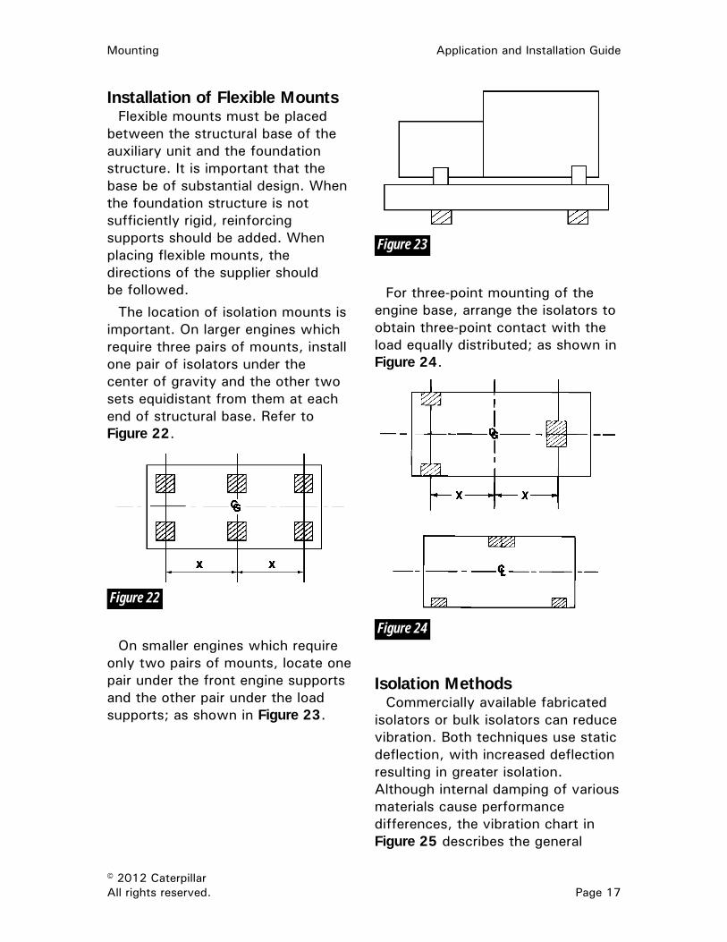
On smaller engines which require only two pairs of mounts, locate one pair under the front engine supports and the other pair under the load supports; as shown in Figure 23.
For three-point mounting of the engine base, arrange the isolators to obtain three-point contact with the load equally distributed; as shown in Figure 24.
Isolation Methods Commercially available fabricated
isolators or bulk isolators can reduce vibration. Both techniques use static deflection, with increased deflection resulting in greater isolation. Although internal damping of various materials cause performance differences, the vibration chart in Figure 25 describes the general
Figure 22
Figure 23
Figure 24

Application and Installation Guide Mounting
© 2012 Caterpillar Page 18 All rights reserved.
effect deflection has on isolation. By using engine rpm as the nominal vibration frequency, magnitude of compression on isolating materials can be estimated.
Several commercial isolators are available which provide varying degrees of isolation. Care must be taken to select the best isolator for the application. In general, the lower the natural frequency of the isolator (softer), the greater the deflection and the more effective the isolation. However, the loading limit of the isolator must not be exceeded.
The unit can be separated from supporting surfaces by these soft
commercial devices, i.e., those that deflect under the static weight.
Mounting rails or fabricated bases withstand torque reactions without uniform support from the isolators.
Basic Vibration Chart
Spring Isolators The most effective isolators of
low frequency vibration are of steel spring design. They can isolate over 96 percent of all vibrations and noise transmitted from rotating machinery to the foundation or mounting surface. Conversely, isolators can absorb disturbances generated by adjacent machinery and prevent damage from being transmitted to idle equipment.
Spring-type linear vibration isolators are available as attachments (not installed) for all generator sets to be used in stationary applications. These isolators permit mounting the generator set on a surface capable of supporting only the static load.
In Figure 26, a detail of a spring-type isolator shows the addition of thrust blocks to restrict lateral movement without interfering with the spring function.
Spring Type Isolator
No allowance for torque or vibratory loads is required. As with
Figure 25
Figure 26

Mounting Application and Installation Guide
© 2012 Caterpillar All rights reserved. Page 19
direct mountings, no anchor bolting is usually required. However, when operating in parallel, vertical restraints are recommended and the isolator must be firmly fastened to the foundation. Spring isolators are available with snubber for use with side-loaded engines or engines located on moving surfaces.
Anchor bolting is not always required, but if the mounts are to be bolted to the foundation, the typical method is to pre-cast multiple anchor bolts into the concrete foundation, necessitating close control of bolt placement location. A preferred method is to drill anchor bolt holes after the generator set is on site, using the isolators for drilling templates. The anchor bolts are then installed and secured with epoxy resin. If necessary, the foundation must be shimmed or grouted (for full surface area of isolator foot) at the isolator locations to provide a surface flat and level within 6.34 mm (0.25 in) for all three isolator contact areas. Elevation differences between isolators should be minimized for the isolators to share the weight evenly when the generator set is horizontal to the foundation.
Steel spring-type isolators are effective in the vibration frequency range from 5 to 1000 Hz.
Marine-type spring isolators should be used for auxiliary engine
mounting. This type of isolator, as shown in Figure 27, is equipped with all directional limit stops designed to restrict excessive movement of the engine and to withstand forces due to roll, pitch and slamming of sea-going vessels.
Many spring type isolators are equipped with horizontal limit stops (snubbers) but do not include built in vertical limit stops. If this type of isolator is used, external vertical limit stops should be added between the engine rail, or support, and the engine bed of the ship. Refer to Figure 28.
Isolator snubbers and limit stops should be adjusted to permit only the amount of motion necessary for isolation purposes.
No matter what type of isolation is used, it should be sized to have a natural frequency as far removed from the exciting frequencies of the engine as possible. If these two frequencies are similar, the entire unit would be in resonance.
When anchor bolting is necessary, they should be installed according to the appropriate isolator installation guidelines. The installation and adjustment of the vibration isolators supplied by Caterpillar are covered in the Special Instructions listed under Reference Material at the end of this section.

Application and Installation Guide Mounting
© 2012 Caterpillar Page 20 All rights reserved.
Marine-Type Isolator
Spring Isolator with External Limit Stop
Rubber Isolators Rubber isolators are adequate for
applications where vibration control is not severe. By careful selection, isolation of 90 percent is possible. They isolate noise created by transmission of vibratory forces. Care must be exercised to avoid using rubber isolators that have the same natural frequency as the
engine exciting frequencies in both vertical and horizontal planes.
By the addition of a rubber pad beneath the spring isolator, the high frequency vibrations, which are transmitted through the spring, are also blocked. These high frequency vibrations are not harmful but result in annoying noise. Refer to Figure 27 and Figure 28.
Figure 27
Figure 28

Mounting Application and Installation Guide
© 2012 Caterpillar All rights reserved. Page 21
Gravel or Sand (Bulk Isolation) Bulk isolating materials are
sometimes used between the foundation and supporting surface, but are not as effective or predictable as spring or rubber types.
Isolation of block foundations may be accomplished by 200 to 250 mm (8 to 10 in) of wet gravel or sand in the bed of the foundation pit. Refer to Figure 29. Wet sand and gravel can reduce engine vibration one-third to one-half. The isolating value of gravel is somewhat greater than sand. To minimize settling of the foundation, gravel or sand must be thoroughly tamped before pouring the concrete block. Make the foundation pit slightly longer and wider than the foundation block base. A wooden form the size and shape of the foundation is placed on the gravel or sand bed for pouring the concrete. After the form is removed, the isolating material is placed around the foundation sides, completely isolating the foundation from the surrounding earth.
Where construction practices allow, the floor, if at the unit's foundation level, should be isolated completely with a soft expansion joint sealing material. Rubber, asphalt impregnated felt, fiberglass, and cork are typical isolating materials, but they may not provide the maximum low frequency isolation. Cork is seldom used under the foundation of modern generator sets because it will rot if not kept dry.
Bulk Isolation
Other Isolation Methods Fiberglass, felt, composition, and
flat rubber of a waffle design do little to isolate major vibration forces, but do isolate much of the high frequency noise. The fabric materials tend to compress with age and become ineffective. Because deflection of these types of isolators is small, their natural frequency is relatively high compared to the engines. Attempting to stack these isolators or apply them indiscriminately could force the total system into resonance. Pad type isolators can be effective for frequencies above 2000 Hz.
Cork is not effective with disturbing frequencies below 1800 cps and, if not kept dry, will rot. It is seldom used with modern generator sets, but is used to separate engine foundations and surrounding floor because of resistance to oil, acid, or temperature changes between -18° and 93°C (0° and 200°F).
Figure 29

Application and Installation Guide Mounting
© 2012 Caterpillar Page 22 All rights reserved.
Stationary equipment isolators are used when the package will not be transported, (with isolators attached), or will not experience seismic shock. The isolators contain thrust blocks to control lateral movement.
External Piping Piping connected to engines or
packaged units requires isolation, particularly when resilient mounts are used. Fuel and water lines, exhaust pipes, and electrical conduit can otherwise transmit vibrations long distances.
If isolator pipe hangers are used, they should have springs to attenuate low frequencies, and rubber or cork to minimize high frequency transmissions. To prevent buildup of resonant vibrations, long runs of piping should be supported at unequal intervals as shown in Figure 30.
External Pipe Supports
Mobile Equipment Isolation from a movable platform
is desirable to:
• Reduce vibration
• Reduce noise
• Prevent torque loading on generator sets caused by platforms or trailer beds.
Isolator for Mobile Equipment
Mobile equipment isolators have the same features as the stationary equipment isolators. They also have built in restraints capable of withstanding a +2 G vertical load and +3 G horizontal load under low cyclic conditions An example is shown in Figure 31. They are suitable for use with mobile platforms, but are not generally intended to handle seismic shock.
Vibration carried throughout an enclosure causes early failure of auxiliary equipment. Relays, switches, gauges, and piping are adversely affected.
Noise, while normally only annoying, can attain levels objection-able to owners and operators. If operating near property lines, noise could exceed local ordinances.
Figure 30
Figure 31

Mounting Application and Installation Guide
© 2012 Caterpillar All rights reserved. Page 23
Perhaps the most important reason to isolate mobile equipment is to avoid bending of the generator set by movement of the sub base. Unless the platform or trailer bed is extremely rigid, the generator set must not be bolted to it. Deflection of the bed would be transmitted to the engine, causing block bending and possible crankshaft and bearing failures.
Lateral movement of the generator set must be minimized as the trailer is transported. This can be achieved simply by blocking the unit off the isolators during the move. If not practical, snubbers can confine vertical and horizontal movement. A spring-type isolator with the addition of thrust blocks restricts
lateral movement without interfering with spring function.
Seismic Seismic shocks are insufficient to
harm generator sets resting on the floor. However, isolation devices, particularly spring isolators, amplify small movement generated by earthquakes to levels that can damage equipment. Special isolators incorporating seismic restraining or damping devices are available, but the isolator supplier must review the exact requirements. Isolators anticipating seismic shock are bolted to the equipment base and the floor. Positive stops are added to limit motion in all directions. Attached piping and auxiliary equipment supports must also tolerate relative movement.

Application and Installation Guide Mounting
© 2012 Caterpillar Page 24 All rights reserved.
Foundations The major functions of a
foundation are to:
• Support total weight of equipment, accessory equipment and fluids (coolant, oil and fuel)
• Maintain alignment between engine, driven equipment, and accessory equipment
• Isolate equipment vibration from surrounding structures.
Responsibility The equipment foundation and the
driven equipment attachment to the foundation are not the responsibility of Caterpillar. The customer or customer's agent, familiar with local site conditions and application requirements, bears foundation design responsibility. Foundation comments published herein are intended only as general guidelines for consideration. Further engine foundation general guidelines can be found in the appropriate Engine Data Sheet.
Ground Loading Initial considerations include
equipment weight and material supporting this weight. The wet weight of the total package must be calculated. This includes accessory equipment and weight of all liquids (coolant, oil, and fuel) supported by the foundation. Dry weights of engine and attachments can be found in the price list. Liquid densities are given in the following table.
Liquid kg/m3 lb/U.S. gal lb/ft3
Specific
Gravity
Water, Fresh
994.6 8.31 62.1 1.001
Water, Sea 1018.3 8.51 63.6 1.021
Water/ Glycol 1024.4 8.55 64.0 1.031
Diesel Fuel 850.7 7.11 53.1 0.855
Lube Oil 909.7 7.61 56.8 0.916
Kerosene 802.7 6.71 50.1 0.807
Material supporting the foundation must carry the total weight. The table below shows the bearing load capabilities of common materials.
Material Safe Bearing
Load
kPa (psi)
Rock, Hardpan 482.6 (70)
Hard Clay, Gravel and Coarse Sand 386 (56)
Loose Medium Sand and Medium Clay 193 (28)
Loose Fine Sand 96.5 (14)
Soft Clay 0-96.5 (0-14)
Firm level soil, gravel, or rock provides satisfactory support for single-bearing generator sets used in stationary or portable service. This support can be used where the weight-bearing capacity of the supporting material exceeds pressure exerted by the equipment package, and where alignment with external machinery is unimportant.

Mounting Application and Installation Guide
© 2012 Caterpillar All rights reserved. Page 25
Soil, such as fine clay, loose sand, or sand near the ground water level, is particularly unstable under dynamic loads and requires substantially larger foundations. Information concerning bearing capacity of soils at the site may be available from local sources and must comply with local building codes.
The area of load-bearing support is adjusted to accommodate surface material. To determine pressure (P) exerted by the generator set, divide total weight (W) by total surface area (A) of the rails, pads, or vibration mounts. Refer to Figure 34.
P = W ÷ A
Where:
P = pressure in (psi)
W= weight in (lb)
A= area in (in2)
Pressure imposed by the weight of the equipment must be less than the load-carrying capacity of supporting material.
Where support rails or mounting feet have insufficient bearing area, flotation pads can distribute the weight. The underside area and stiffness of the pad must be sufficient to support the equipment.
Seasonal and weather changes adversely affect mounting surfaces. Soil changes considerably while freezing and thawing. To avoid movement from seasonal change, extend foundations below the frost line.
Concrete Several basic foundations are
applicable for Cat equipment. The foundation chosen will depend on factors previously outlined as well as limitations imposed by the specific location and application.
Massive concrete foundations are normally unnecessary for modern multi-cylinder medium speed engines and packaged units. Avoid excessively thick, heavy bases to minimize sub floor or soil loading. Bases should be only thick enough to prevent deflection and torque reaction, while retaining sufficient surface area for support. Non-parallel units require no foundation anchoring.
Figure 34

Application and Installation Guide Mounting
© 2012 Caterpillar Page 26 All rights reserved.
If a concrete foundation is required, minimum design guidelines include:
• Strength must support wet weight of units plus dynamic loads. The dynamic load can be calculated using the allowable centerline vibration limits and the equipment mass.
• Depth sufficient to attain a minimum weight equal to equipment wet weight (only if large mass, i.e. inertia block, is specified for vibration control).
• The mass of the foundation should be no less than the mass of the equipment.
• Outside dimensions exceed that of the equipment, a minimum of 305 mm (12 in) on all sides.
• When effective vibration isolation equipment is used, figure depth of floor concrete needed for structural support of the static load. If isolators are not used, dynamic loads transmit to the facility floor and require the floor to support 125 percent of the generator set weight.
• If generator sets are paralleled, possible out-of-phase paralleling and resulting torque reactions demand stronger foundations. The
foundation must withstand twice the wet weight of the generator set. Bolting the set to the foundation is recommended.
Estimate foundation depth that will accommodate equipment weight using the formula:
FD = W ÷ (D x B x L)
Where:
FD = Foundation depth in m (ft)
W = Total wet weight of equipment in kg (lb)
D = Density of concrete in kg/m2 (lb/ft2)
Note: Use 2402.8 for metric units and 150 for English units.
B = Foundation width in m (ft)
L = Foundation length in m (ft)
Suggested concrete mixture by volume is 1:2:3 of cement, sand, aggregate, with maximum 102 mm (4 in) slump and 28-day compressive strength of 21 mPa (3000 psi).
Reinforce concrete with No. 8 gauge steel wire mesh, or equivalent, horizontally placed on 152 mm (6 in) centers. An alternative method places No. 6 reinforcing bars on 305 mm (12 in) centers horizontally. Bars must clear foundation surfaces 76 mm (3 in) minimum. Refer to Figure 35.

Mounting Application and Installation Guide
© 2012 Caterpillar All rights reserved. Page 27
Concrete Foundation Example
Figure 35

Application and Installation Guide Mounting
© 2012 Caterpillar Page 28 All rights reserved.
Bases
Purpose and Function The most important function of
an engine base is rigidity. It must maintain alignment between the engine and its driven equipment. The major cause of misalignment is flexing of the base due to lack of torsional rigidity. Other causes are poor installation methods and incorrect alignment procedures.
The base must offer rigidity adequate to oppose the twist due to torque reaction on drives where the driven equipment is mounted on the base assembly, but not bolted directly to the engine flywheel housing.
In general, Cat engine bases will:
• Protect the engine block, drive train couplings, and driven equipment (generator gear reducer, or pump) from bending forces during ship-ment. The entire package must be able to withstand normal handling during transportation without permanently distorting the base or causing misalignment of the driven equipment.
• Limit torsional and bending moment forces caused by torque reaction and flexing of the foundation or substructure under the base.
• Be free of torsional or linear vibration in the operating speed range of the engine, and have a natural frequency
such that resonance does not occur during the machinery's normal work.
• Make proper alignment easy, and maintain this alignment under all operational and environmental conditions, thus eliminating the need for frequent, periodic realignment of the engine and driven equipment. Allow sufficient space for shimming in the alignment process.
• Provide proper mounting holes for the engine and all other base mounted components.
Note: Bases designed and fabricated by dealers, or others, must meet the design requirements of Caterpillar supplied bases to assure strength and vibration resistance.
Caterpillar Base Design Ease of initial installation, vibration
isolation, and need for isolation from flexing mounting surfaces are major reasons for using fabricated bases. No base of any type should be rigidly connected to a flexing mounting surface.
The type of load will also determine specific design features required in an engine base. Caterpillar offers different bases for close-coupled units (such as single bearing generators) and for remote mounted units (such as two bearing generators).

Mounting Application and Installation Guide
© 2012 Caterpillar All rights reserved. Page 29
Single Bearing Loads When single-bearing generators or
close-coupled loads are used, the base does not have to withstand torque reaction. Bolting the generator housing to the flywheel housing eliminates the need for the base to absorb the driving torque of the engine. Refer to Figure 36.
Single Bearing Loads
Two Bearing Loads With the load remote-mounted,
a more rigid structural base is required. The full load torque between the engine and load has to be absorbed by the base without causing excessive deflection in the coupling.
The stationary frame of the remote-mounted driven equipment torques in the same direction as the engine crankshaft. Refer to
Figure 37. If the base were not rigid enough, engine torque would cause the base to flex excessively. The result is misalignment, proportional to the amount of load, which will not show up during a conventional static alignment check.
Severe cases of this problem result in bearing and coupling failures.
Two Bearing Loads
Bases for Engines with Close-Coupled Loads
Caterpillar does not recommend a specific section modulus for the longitudinal girders or cross members. Usually I-beams or channel section steel beams in a ladder-type arrangement are acceptable.
Figure 36
Figure 37

Application and Installation Guide Mounting
© 2012 Caterpillar Page 30 All rights reserved.
Base for Foot Mounted Engine with Close Coupled Load
Foot-Mounted Engines Bases for foot-mounted engines
should have cross members as substantial as the longitudinal beams. Place these cross members beneath each engine and driven unit support location.
Do not fasten the engine and driven unit mounting feet to the base by welding.
Use drilled and tapped steel mounting blocks between the engine/driven equipment and the base. Refer to Figure 38. Bolt these blocks to the engine/driven
equipment first and then weld to the base providing a flat surface for shimming and mounting. Mounting holes drilled into the structural members of the base are not recommended.
There should be sufficient space for shimming between the mounting blocks and the engine/driven equipment mounting surfaces.
Flexible mounts are not allowed between the mounting blocks and the engine/load mounting foot surfaces.
Figure 38

Mounting Application and Installation Guide
© 2012 Caterpillar All rights reserved. Page 31
Base for Rail Mounted Engine with Close Coupled Load
Rail-Mounted Engines Refer to Figure 39. In addition to
the requirements for foot-mounted engines, the following applies for rail-mounted engines:
• The standard engine-mounted support rails (engine length) must be used between the engine and the structural base.
• Locate cross members directly beneath the front and rear engine-to-rail mounting locations.
• Place drilled and tapped mounting blocks at the front and rear of the engine-mounted rails with space
available for shimming. Bolt these blocks to the engine/driven equipment first and then weld to the base to provide a flat surface for shimming and mounting.
• Do not weld the engine-mounted rail to the structural base.
• Bolt the engine-mounted rails to the threaded mounting blocks through clearance holes to allow for thermal growth.
Figure 39

Application and Installation Guide Mounting
© 2012 Caterpillar Page 32 All rights reserved.
Base for Engines with Remote Mounted Driven Equipment
Bases for Engines with Remote-Mounted Loads
The design requirements for bases used on engines with close-coupled units also apply to bases used for engines with remote-mounted units. Bases for use with remote-mounted units must be more rigid. The base must absorb the full-load torque between the engine and driven unit without causing excessive deflection in the coupling.
The base shown in Figure 40 is a boxed beam design that provides a torsionally rigid base.
Boxing consists of welding steel plates on top and bottom surfaces of machinery base girders. Skip-weld the plates to prevent excessive base
distortion during welding. Boxing is done to make the base structure stiffer.
The additional stiffness is necessary to resist torque loads between the engine and remote-mounted driven equipment and to resist possible vibration loads. Vibration-induced base loads are difficult to predict.
Experience has shown boxing is effective in preventing base cracking and misalignment.
Cat Special Duty Bases
Offshore Power Modules The Cat petroleum offshore base
consists of a base-within-a-base. The inner base is three-point mounted, with integral spring
Figure 40

Mounting Application and Installation Guide
© 2012 Caterpillar All rights reserved. Page 33
isolators and limit stops, to the outer base. The outer base can be welded to the rig support structure. The inner base structure is not the same as engine rails used in other applications. Refer to Figure 41.
The outer base must be supported by large girders, and can either be welded or bolted to the rig structure. Inadequate support may result in power module vibrations.
Offshore Power Module
Land Rig Power Modules The Cat petroleum land rig base
uses 460 mm (18 in) wide flange beams, available in lengths of 7.85 m, 9.37 m and 12.42 m (25 ft 9 in, 30 ft 9 in and 40 ft 9 in), to allow matching base length to equipment needs. As with the offshore power modules, alignment integrity is provided by using a base-within-a-
base design as shown in Figure 42 and Figure 43.
The 12.42 m (40 ft 9 in) base has no decking provided from the rear of the generator to the rear of the base. Customer-supplied auxiliary equipment is to be mounted here, necessitating customer-supplied decking and reinforcement.
Site preparation is generally required for land rig power modules in order to provide level, firm soil. In some cases, planking or concrete surfacing may be necessary. Certain types of soil, such as fine clay, loose sand, sand near the ground water level, or soil that is freezing or thawing, are particularly unstable under dynamic loads. Loose planking under the power modules may also cause power module vibration.
Because ground conditions may vary from well location to well location, vibrations may result which are not due to misalignment or unbalanced parts. Unstable ground, as previously mentioned, may be reacting to normal forces within the engine/generator combination, whereas at another well location no such reaction may occur.
In addition, rough handling may occur during rig moves, so alignment should be checked after every move.
Figure 41

Application and Installation Guide Mounting
© 2012 Caterpillar Page 34 All rights reserved.
Land Rig Power Module
Land Rig Power Module
Figure 42
Figure 43

Mounting Application and Installation Guide
© 2012 Caterpillar All rights reserved. Page 35
Roof and Walkway The customer can add roofs and
walkway wings for servicing and weather protection, as shown in Figure 44. The width of the wings should suit the customer, but should be at least as wide as the radiator. All connections of the bracing to the base should avoid stressing or flexing the I-beam's flange or vertical member. Guard rails, cable runs, lighting, exhaust piping, etc., can be added according to customer preference.
Figure 44

Application and Installation Guide Mounting
© 2012 Caterpillar Page 36 All rights reserved.
Reference MaterialThe following information is
provided as an additional reference to subjects discussed in this guide.
SEHS8700 Special Instruction - Installation of Flexible Mounting Groups
SEHS9162 Special Instruction - Spring Isolator Group Installation and Adjustment Procedure


© 2008 Caterpillar® Page 38 All rights reserved.
LEBW4974-05 ©2012 Caterpillar Printed in U.S.A. All rights reserved.