
Mounting instructions SP Positioner TemplatePositioner SPLC
153
L Global Drive Software package - Positioner Template Positioner 9300 Servo PLC Manual
Transcript of Mounting instructions SP Positioner TemplatePositioner SPLC

L
Global Drive
Software package - PositionerTemplate Positioner
9300 Servo PLC
Manual

This documentation applies to Template Positioner as of version 5.0.
Template Positioner can be used for the following Lenze PLCs:
Type as of hardware version as of software version
9300 Servo PLC EVS93XX−xT 6A 6.0
Software system requirements:
Drive PLC Developer Studio Professional as of version 2.2
Important note:
The software is supplied to the user as described in this document. Any risks resulting from its quality or use remain the responsibilityof the user. The user must provide all safety measures protecting against possible maloperation.
We do not take any liability for direct or indirect damage, e.g. profit loss, order loss or any loss regarding business.
� 2008 Lenze Drive Systems GmbH
No part of this documentation may be copied or made available to third parties without the explicit written approval of Lenze DriveSystems GmbH.
All information given in this documentation has been carefully selected and tested for compliance with the hardware and softwaredescribed. Nevertheless, discrepancies cannot be ruled out. We do not accept any responsibility or liability for any damage that mayoccur. Required corrections will be included in updates of this documentation.
All product names mentioned in this documentation are trademarks of the corresponding owners.
Version 4.0 04/2008

Template PositionerContents
il TP Positioner Servo PLC 5.0 EN
1 Preface and general information 1−1 . . . . . . . . . . . . . . . . . . . . . . . . . . . . . . . . . . . . . . . . . . .
1.1 About this Manual 1−1 . . . . . . . . . . . . . . . . . . . . . . . . . . . . . . . . . . . . . . . . . . . . . . . . . . . . . . . . . . . . . . . .
1.1.1 Conventions used in this Manual 1−1 . . . . . . . . . . . . . . . . . . . . . . . . . . . . . . . . . . . . . . . . . . . . . .
1.1.2 Pictographs used in this Manual 1−1 . . . . . . . . . . . . . . . . . . . . . . . . . . . . . . . . . . . . . . . . . . . . . . .
1.1.3 Terminology used 1−2 . . . . . . . . . . . . . . . . . . . . . . . . . . . . . . . . . . . . . . . . . . . . . . . . . . . . . . . . .
1.2 Information about the template version 1−2 . . . . . . . . . . . . . . . . . . . . . . . . . . . . . . . . . . . . . . . . . . . . . . . . .
1.3 Supported functions 1−3 . . . . . . . . . . . . . . . . . . . . . . . . . . . . . . . . . . . . . . . . . . . . . . . . . . . . . . . . . . . . . . .
2 Positioning basics 2−1 . . . . . . . . . . . . . . . . . . . . . . . . . . . . . . . . . . . . . . . . . . . . . . . . . . . . . .
2.1 What does positioning mean? 2−1 . . . . . . . . . . . . . . . . . . . . . . . . . . . . . . . . . . . . . . . . . . . . . . . . . . . . . . . .
2.2 Terminology used 2−1 . . . . . . . . . . . . . . . . . . . . . . . . . . . . . . . . . . . . . . . . . . . . . . . . . . . . . . . . . . . . . . . . .
2.2.1 Profile 2−1 . . . . . . . . . . . . . . . . . . . . . . . . . . . . . . . . . . . . . . . . . . . . . . . . . . . . . . . . . . . . . . . . . .
2.2.2 Position 2−2 . . . . . . . . . . . . . . . . . . . . . . . . . . . . . . . . . . . . . . . . . . . . . . . . . . . . . . . . . . . . . . . . .
2.2.3 Speed 2−2 . . . . . . . . . . . . . . . . . . . . . . . . . . . . . . . . . . . . . . . . . . . . . . . . . . . . . . . . . . . . . . . . . .
2.2.4 Acceleration/deceleration 2−3 . . . . . . . . . . . . . . . . . . . . . . . . . . . . . . . . . . . . . . . . . . . . . . . . . . .
2.2.5 Jerk reduction by means of S−profiles 2−3 . . . . . . . . . . . . . . . . . . . . . . . . . . . . . . . . . . . . . . . . . .
2.2.6 Homing 2−4 . . . . . . . . . . . . . . . . . . . . . . . . . . . . . . . . . . . . . . . . . . . . . . . . . . . . . . . . . . . . . . . . .
2.2.7 Manual homing 2−4 . . . . . . . . . . . . . . . . . . . . . . . . . . . . . . . . . . . . . . . . . . . . . . . . . . . . . . . . . . .
2.2.8 Remaining path positioning (touch probe) 2−5 . . . . . . . . . . . . . . . . . . . . . . . . . . . . . . . . . . . . . . . .
2.2.9 Profile change during positioning (override) 2−5 . . . . . . . . . . . . . . . . . . . . . . . . . . . . . . . . . . . . . . .
2.2.10 Overchange 2−6 . . . . . . . . . . . . . . . . . . . . . . . . . . . . . . . . . . . . . . . . . . . . . . . . . . . . . . . . . . . . . .
2.2.11 Limit positions 2−6 . . . . . . . . . . . . . . . . . . . . . . . . . . . . . . . . . . . . . . . . . . . . . . . . . . . . . . . . . . . .
2.3 Machine parameters 2−7 . . . . . . . . . . . . . . . . . . . . . . . . . . . . . . . . . . . . . . . . . . . . . . . . . . . . . . . . . . . . . .
3 Introduction 3−1 . . . . . . . . . . . . . . . . . . . . . . . . . . . . . . . . . . . . . . . . . . . . . . . . . . . . . . . . . . .
3.1 What is a template? 3−1 . . . . . . . . . . . . . . . . . . . . . . . . . . . . . . . . . . . . . . . . . . . . . . . . . . . . . . . . . . . . . . .
3.1.1 Applications for a template 3−1 . . . . . . . . . . . . . . . . . . . . . . . . . . . . . . . . . . . . . . . . . . . . . . . . . .
3.2 Software architecture 3−2 . . . . . . . . . . . . . . . . . . . . . . . . . . . . . . . . . . . . . . . . . . . . . . . . . . . . . . . . . . . . . .
3.2.1 Basic concept 3−3 . . . . . . . . . . . . . . . . . . . . . . . . . . . . . . . . . . . . . . . . . . . . . . . . . . . . . . . . . . . .
3.2.2 Application layer 3−3 . . . . . . . . . . . . . . . . . . . . . . . . . . . . . . . . . . . . . . . . . . . . . . . . . . . . . . . . . .
3.2.3 Template interface 3−4 . . . . . . . . . . . . . . . . . . . . . . . . . . . . . . . . . . . . . . . . . . . . . . . . . . . . . . . . .
3.2.4 Target interface 3−4 . . . . . . . . . . . . . . . . . . . . . . . . . . . . . . . . . . . . . . . . . . . . . . . . . . . . . . . . . . .
3.2.5 Template 3−4 . . . . . . . . . . . . . . . . . . . . . . . . . . . . . . . . . . . . . . . . . . . . . . . . . . . . . . . . . . . . . . . .
4 Template commissioning 4−1 . . . . . . . . . . . . . . . . . . . . . . . . . . . . . . . . . . . . . . . . . . . . . . . . .
4.1 Preconditions 4−1 . . . . . . . . . . . . . . . . . . . . . . . . . . . . . . . . . . . . . . . . . . . . . . . . . . . . . . . . . . . . . . . . . . . .
4.2 General information about the sequential function chart 4−2 . . . . . . . . . . . . . . . . . . . . . . . . . . . . . . . . . . . . .
4.3 Sequential function chart for commissioning the template 4−3 . . . . . . . . . . . . . . . . . . . . . . . . . . . . . . . . . . .
5 The "Positioning" status machine 5−1 . . . . . . . . . . . . . . . . . . . . . . . . . . . . . . . . . . . . . . . . . .
5.1 Short status description 5−2 . . . . . . . . . . . . . . . . . . . . . . . . . . . . . . . . . . . . . . . . . . . . . . . . . . . . . . . . . . . .
5.2 Conditions for status changes (transitions) 5−4 . . . . . . . . . . . . . . . . . . . . . . . . . . . . . . . . . . . . . . . . . . . . . .
5.3 Status "StandBy" 5−6 . . . . . . . . . . . . . . . . . . . . . . . . . . . . . . . . . . . . . . . . . . . . . . . . . . . . . . . . . . . . . . . . .
5.3.1 Function "ExternalSetValuePositioning" 5−7 . . . . . . . . . . . . . . . . . . . . . . . . . . . . . . . . . . . . . . . . .
5.3.2 Function "PositionTeach" 5−9 . . . . . . . . . . . . . . . . . . . . . . . . . . . . . . . . . . . . . . . . . . . . . . . . . . . .
5.3.3 Function "StaticHomePositionSet" 5−10 . . . . . . . . . . . . . . . . . . . . . . . . . . . . . . . . . . . . . . . . . . . . .

Template PositionerContents
ii lTP Positioner Servo PLC 5.0 EN
5.4 Status "Homing" 5−13 . . . . . . . . . . . . . . . . . . . . . . . . . . . . . . . . . . . . . . . . . . . . . . . . . . . . . . . . . . . . . . . . .
5.4.1 Function "Homing" 5−14 . . . . . . . . . . . . . . . . . . . . . . . . . . . . . . . . . . . . . . . . . . . . . . . . . . . . . . . .
5.5 Status "ManualJog" 5−21 . . . . . . . . . . . . . . . . . . . . . . . . . . . . . . . . . . . . . . . . . . . . . . . . . . . . . . . . . . . . . . .
5.5.1 Function "ManualJog" 5−22 . . . . . . . . . . . . . . . . . . . . . . . . . . . . . . . . . . . . . . . . . . . . . . . . . . . . . .
5.6 Status "Positioning" 5−27 . . . . . . . . . . . . . . . . . . . . . . . . . . . . . . . . . . . . . . . . . . . . . . . . . . . . . . . . . . . . . . .
5.6.1 General information 5−28 . . . . . . . . . . . . . . . . . . . . . . . . . . . . . . . . . . . . . . . . . . . . . . . . . . . . . . . .
5.6.2 Function "StandardPositioning" 5−35 . . . . . . . . . . . . . . . . . . . . . . . . . . . . . . . . . . . . . . . . . . . . . . .
5.6.3 Function "TouchProbePositioning" 5−44 . . . . . . . . . . . . . . . . . . . . . . . . . . . . . . . . . . . . . . . . . . . . .
5.6.4 Function "OverchangePositioning" 5−53 . . . . . . . . . . . . . . . . . . . . . . . . . . . . . . . . . . . . . . . . . . . . .
5.6.5 Function "OverridePositioning" 5−61 . . . . . . . . . . . . . . . . . . . . . . . . . . . . . . . . . . . . . . . . . . . . . . . .
5.6.6 Function "ChangeProfileInterface" 5−71 . . . . . . . . . . . . . . . . . . . . . . . . . . . . . . . . . . . . . . . . . . . . .
5.6.7 Function "PositionCorrection" 5−73 . . . . . . . . . . . . . . . . . . . . . . . . . . . . . . . . . . . . . . . . . . . . . . . .
5.7 Parallel processes "PosFunctions" 5−77 . . . . . . . . . . . . . . . . . . . . . . . . . . . . . . . . . . . . . . . . . . . . . . . . . . . .
5.7.1 Function "TemplateControl" 5−78 . . . . . . . . . . . . . . . . . . . . . . . . . . . . . . . . . . . . . . . . . . . . . . . . . .
6 Program Organisation Units (POUs) 6−1 . . . . . . . . . . . . . . . . . . . . . . . . . . . . . . . . . . . . . . . . .
6.1 Troubleshooting − POU "UserErrors" 6−1 . . . . . . . . . . . . . . . . . . . . . . . . . . . . . . . . . . . . . . . . . . . . . . . . . . .
6.2 Positioning sequencer − POU "UserInterface" 6−3 . . . . . . . . . . . . . . . . . . . . . . . . . . . . . . . . . . . . . . . . . . . . .
6.2.1 POU to call up individual programs 6−3 . . . . . . . . . . . . . . . . . . . . . . . . . . . . . . . . . . . . . . . . . . . . .
6.2.2 Use of the positioning sequencer 6−4 . . . . . . . . . . . . . . . . . . . . . . . . . . . . . . . . . . . . . . . . . . . . . .
7 Appendix 7−1 . . . . . . . . . . . . . . . . . . . . . . . . . . . . . . . . . . . . . . . . . . . . . . . . . . . . . . . . . . . . .
7.1 Technical data 7−1 . . . . . . . . . . . . . . . . . . . . . . . . . . . . . . . . . . . . . . . . . . . . . . . . . . . . . . . . . . . . . . . . . . .
7.2 Global variables 7−2 . . . . . . . . . . . . . . . . . . . . . . . . . . . . . . . . . . . . . . . . . . . . . . . . . . . . . . . . . . . . . . . . . .
7.2.1 VarChangeProfileInterface 7−2 . . . . . . . . . . . . . . . . . . . . . . . . . . . . . . . . . . . . . . . . . . . . . . . . . . .
7.2.2 VarExternalSetValues 7−3 . . . . . . . . . . . . . . . . . . . . . . . . . . . . . . . . . . . . . . . . . . . . . . . . . . . . . . .
7.2.3 VarHardwareSignals 7−3 . . . . . . . . . . . . . . . . . . . . . . . . . . . . . . . . . . . . . . . . . . . . . . . . . . . . . . . .
7.2.4 VarHoming 7−3 . . . . . . . . . . . . . . . . . . . . . . . . . . . . . . . . . . . . . . . . . . . . . . . . . . . . . . . . . . . . . .
7.2.5 VarManualJog 7−4 . . . . . . . . . . . . . . . . . . . . . . . . . . . . . . . . . . . . . . . . . . . . . . . . . . . . . . . . . . . .
7.2.6 VarOverchange 7−4 . . . . . . . . . . . . . . . . . . . . . . . . . . . . . . . . . . . . . . . . . . . . . . . . . . . . . . . . . . .
7.2.7 VarOverride 7−5 . . . . . . . . . . . . . . . . . . . . . . . . . . . . . . . . . . . . . . . . . . . . . . . . . . . . . . . . . . . . . .
7.2.8 VarPositionCorrection 7−5 . . . . . . . . . . . . . . . . . . . . . . . . . . . . . . . . . . . . . . . . . . . . . . . . . . . . . . .
7.2.9 VarPositioning 7−6 . . . . . . . . . . . . . . . . . . . . . . . . . . . . . . . . . . . . . . . . . . . . . . . . . . . . . . . . . . . .
7.2.10 VarPositionTeach 7−8 . . . . . . . . . . . . . . . . . . . . . . . . . . . . . . . . . . . . . . . . . . . . . . . . . . . . . . . . . .
7.2.11 VarTemplateControl 7−8 . . . . . . . . . . . . . . . . . . . . . . . . . . . . . . . . . . . . . . . . . . . . . . . . . . . . . . . .
7.2.12 VarTemplateSettings (constant) 7−9 . . . . . . . . . . . . . . . . . . . . . . . . . . . . . . . . . . . . . . . . . . . . . . .
7.2.13 VarTouchProbe 7−10 . . . . . . . . . . . . . . . . . . . . . . . . . . . . . . . . . . . . . . . . . . . . . . . . . . . . . . . . . . .
7.3 Reserved input variables of the target interface 7−11 . . . . . . . . . . . . . . . . . . . . . . . . . . . . . . . . . . . . . . . . . . .
7.4 Settings 7−12 . . . . . . . . . . . . . . . . . . . . . . . . . . . . . . . . . . . . . . . . . . . . . . . . . . . . . . . . . . . . . . . . . . . . . . . .
7.4.1 Number of positioning profiles 7−12 . . . . . . . . . . . . . . . . . . . . . . . . . . . . . . . . . . . . . . . . . . . . . . . .
7.4.2 Number of measuring points for feed correction 7−12 . . . . . . . . . . . . . . . . . . . . . . . . . . . . . . . . . . .
7.4.3 Profile names − data type "ProfileNames (ENUM)" 7−12 . . . . . . . . . . . . . . . . . . . . . . . . . . . . . . . . . .
7.4.4 Error messages − data type "ErrorCode (ENUM)" 7−13 . . . . . . . . . . . . . . . . . . . . . . . . . . . . . . . . . . .
7.5 Code list 7−15 . . . . . . . . . . . . . . . . . . . . . . . . . . . . . . . . . . . . . . . . . . . . . . . . . . . . . . . . . . . . . . . . . . . . . . .
7.6 Visualisation 7−27 . . . . . . . . . . . . . . . . . . . . . . . . . . . . . . . . . . . . . . . . . . . . . . . . . . . . . . . . . . . . . . . . . . . .
8 Index 8−1 . . . . . . . . . . . . . . . . . . . . . . . . . . . . . . . . . . . . . . . . . . . . . . . . . . . . . . . . . . . . . . . .

Template Positioner1 Preface and general information
1−1L TP Positioner Servo PLC 5.0 EN
1 Preface and general information
1.1 About this Manual
This Manual contains information about the Template Positioner for the Drive PLC DeveloperStudio.
� Template Positioner can be used to implement positioning functions in a PLC.
� In addition to the positioning functionality, the Template Positioner includes manypre−designed solutions which can help to save precious time.
� The template is part of the Software Package − Positioner.
1.1.1 Conventions used in this Manual
This Manual uses the following conventions to distinguish between different types of information:
Variable identifiers
are written in italics in the explanation:
� "Use bReset_b..."
Tip!
Information about the conventions used for the variables of Lenze system blocks, functions blocksand functions can be found in the appendix of the DDS online documentation "Introduction intoIEC 61131−3 programming".The conventions ensure universal labelling.
Lenze functions/function blocks
can be recognised by their names. They always begin with an "L_":
� "The FB L_MCProfileGenerator..."
Program listings
are written in "Courier", keywords are printed in bold:
� "IF (ReturnValue < 0) THEN..."
1.1.2 Pictographs used in this Manual
Use ofpictographs
Signal words
Warning ofmaterial damage
STOP! Warns of potential damage to material.
Possible consequences if disregarded:
Damage to the controller/drive system or its environment.
Other notes Tip!
Note!
Indicates a tip or note.

1 Preface and general information
Template Positioner
1−2 LTP Positioner Servo PLC 5.0 EN
1.1.3 Terminology used
Term In the following text used for
Cxxxx/y Subcode y of code Cxxxx (e.g. C0470/3 = subcode 3 of code C0470)
DDS Drive PLC Developer Studio
FB Function block
GDC Global Drive Control (parameterisation program from Lenze)
Parameter Code used to set the functionality of a function block or template function
PLC 9300 Servo PLC
QSP Quick stop
SB System block
System bus (CAN) Lenze standard bus system similar to CANopen for
� communication with a host system or other controllers
� parameter setting and diagnostics
[unit] Wildcard for the physical unit of the external measuring system (e.g. "�m", "mm", "cm")
1.2 Information about the template version
As of template version 3.04 you can find information about the version of Template Positioner underthe following global constants:
Constant MeaningExample
value
C_w[TemplateName]VersionER External release 03
C_w[TemplateName]VersionEL External level 04
C_w[TemplateName]VersionIR Internal release 00
C_w[TemplateName]VersionBN Build number 00
Version: 03 04 00 00
� In the example, the value "03040000" stands for version "3.04.00.00".
� Code C3999 indicates the version in form of the value "3040000".

Template Positioner1 Preface and general information
1−3L TP Positioner Servo PLC 5.0 EN
1.3 Supported functions
The Template Positioner supports the following functions:
� Positioning in different modes:
– Absolute positioning
– Modulo positioning (no integrator overflow, e.g. for round tables)
– Constant traversing
– Relative positioning (integrator overflow possible)
– Remaining path positioning (touch probe)
� Profile change during positioning (override)
� Overchange
� Manual positioning
� Homing (16 different modes)
� Jerk limitation/S−ramps for acceleration/deceleration
� "Teach−in" function for easy selection of target positions
� Easy implementation of sequences in different IEC 61131 programming languages
� Profile selection via codes
� Profile selection via program parameters, variables or fieldbus process data with the help ofthe template function "ChangeProfileInterface"
� Profiles get symbolic names
� Creation of individual error routines and error messages
� Immediate new positioning during an active positioning process
� Operation and diagnostics of template functions via a visualisation
� Visualisation of calculated profiles (profile analysis), template states and signal flows

1 Preface and general information
Template Positioner
1−4 LTP Positioner Servo PLC 5.0 EN

Template Positioner2 Positioning basics
2−1L TP Positioner Servo PLC 5.0 EN
2 Positioning basics
The following sections describe positioning basics.
The functions supported by the template are described in chapter 1.3 (� 1−3).
2.1 What does positioning mean?
Positioning means to move one or several machine components from a start position to a definedtarget:
� �
Fig. 2−1 Positioning = Moving machine components from a start position � to a defined target �
2.2 Terminology used
2.2.1 Profile
"Profiles" define a positioning process, i.e. profiles determine:
� target
� maximum speed
� acceleration time until maximum speed is reached
� deceleration time from maximum speed to target position
� final speed when reaching the target position
� maximum jerk (jerk = derivation of acceleration)
A profile consists of the following parameters: Position, speed, acceleration, deceleration, finalspeed and jerk and can be indicated as a graphic:
v [m/s]
t [s]
��
�
�
vpos
�
t [s]
vend �
�
Fig. 2−2 Positioning profile
� Acceleration � Deceleration
� Positioning speed � Target position
� Distance (= trapezium area) � Final speed (here other than "0")
Positioning is built up from many profiles processed in a defined way.
2 Positioning basics
Template Positioner
2−2 LTP Positioner Servo PLC 5.0 EN
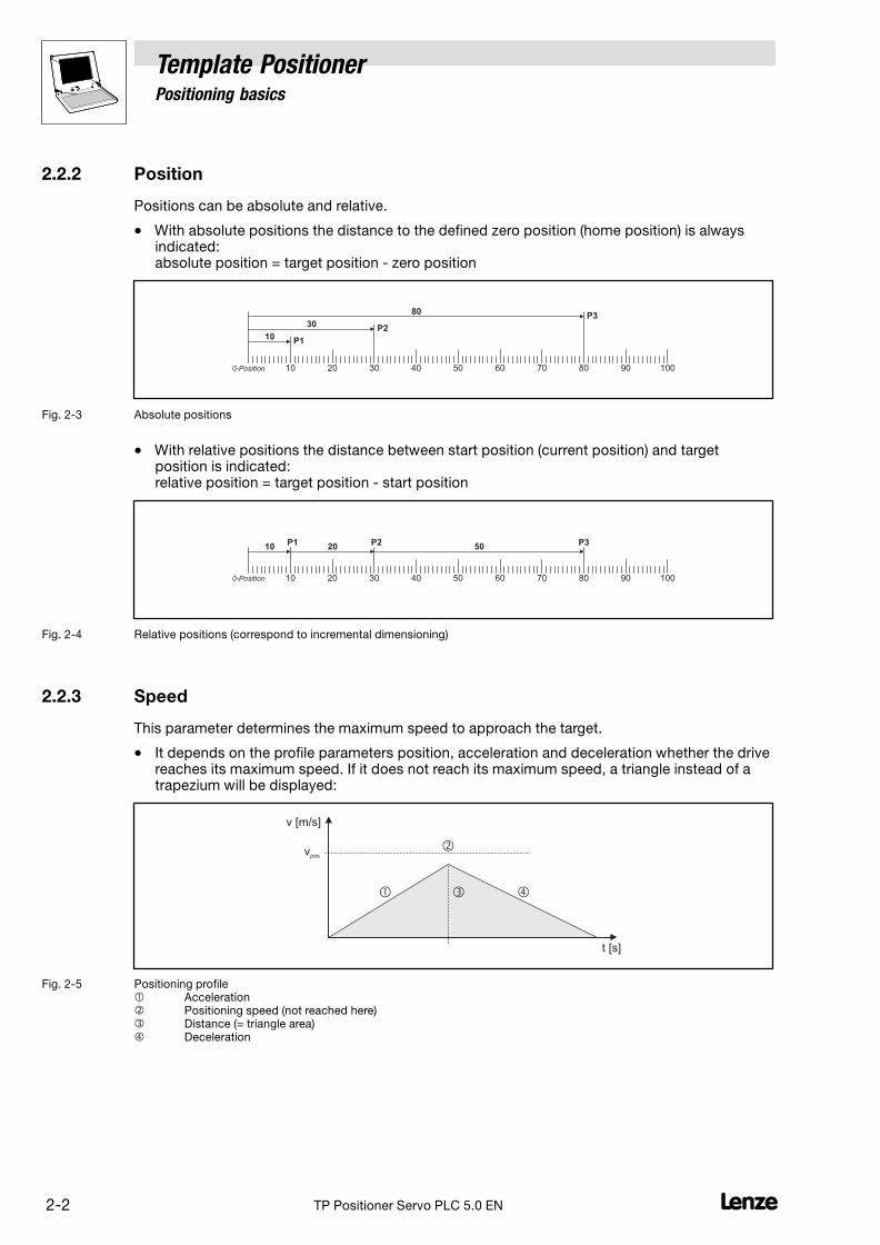
2.2.2 Position
Positions can be absolute and relative.
� With absolute positions the distance to the defined zero position (home position) is alwaysindicated:absolute position = target position − zero position
0-Position 10 20 30 40 50 60 70 80 90 100
10
30
80
P1
P2
P3
Fig. 2−3 Absolute positions
� With relative positions the distance between start position (current position) and targetposition is indicated:relative position = target position − start position
0-Position 10 20 30 40 50 60 70 80 90 100
10 20 50P3P2P1
Fig. 2−4 Relative positions (correspond to incremental dimensioning)
2.2.3 Speed
This parameter determines the maximum speed to approach the target.
� It depends on the profile parameters position, acceleration and deceleration whether the drivereaches its maximum speed. If it does not reach its maximum speed, a triangle instead of atrapezium will be displayed:
v [m/s]
t [s]
��
�
�
vpos
Fig. 2−5 Positioning profile � Acceleration� Positioning speed (not reached here)� Distance (= triangle area)� Deceleration
Template Positioner2 Positioning basics
2−3L TP Positioner Servo PLC 5.0 EN
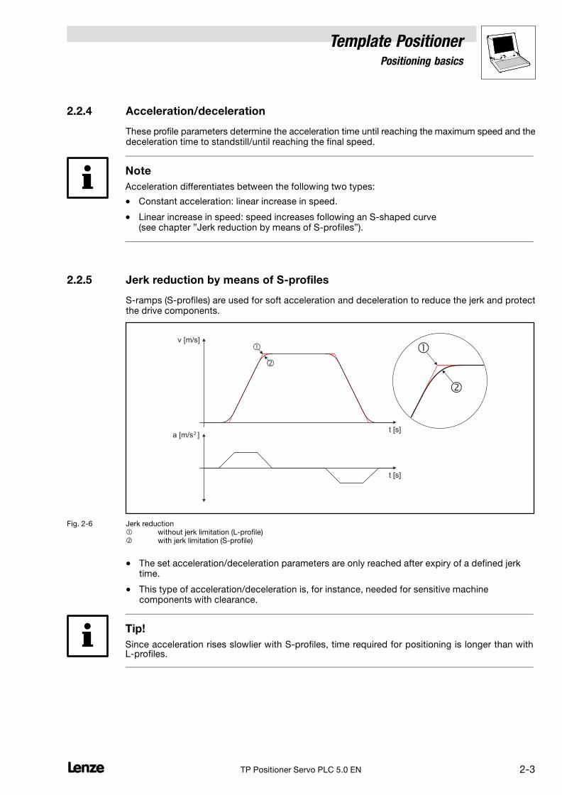
2.2.4 Acceleration/deceleration
These profile parameters determine the acceleration time until reaching the maximum speed and thedeceleration time to standstill/until reaching the final speed.
Note
Acceleration differentiates between the following two types:
� Constant acceleration: linear increase in speed.
� Linear increase in speed: speed increases following an S−shaped curve(see chapter "Jerk reduction by means of S−profiles").
2.2.5 Jerk reduction by means of S−profiles
S−ramps (S−profiles) are used for soft acceleration and deceleration to reduce the jerk and protectthe drive components.
v [m/s]
t [s]
a [m/s ]
�
�
t [s]2
�
�
Fig. 2−6 Jerk reduction� without jerk limitation (L−profile)� with jerk limitation (S−profile)
� The set acceleration/deceleration parameters are only reached after expiry of a defined jerktime.
� This type of acceleration/deceleration is, for instance, needed for sensitive machinecomponents with clearance.
Tip!
Since acceleration rises slowlier with S−profiles, time required for positioning is longer than withL−profiles.

2 Positioning basics
Template Positioner
2−4 LTP Positioner Servo PLC 5.0 EN
2.2.6 Homing
The measuring system in the machine is selected by means of homing and the zero position is setwithin the possible traversing range:
0-Position10 20 30 40 50 60-10
Fig. 2−7 Homing (selection of zero position)
The zero position (home) can be defined by homing or setting a home position:
� With homing the drive follows a previously selected path to find the home position.
� When the drive stands still, the home position is selected manually.
2.2.7 Manual homing
Manual homing means that the drive is moved by manual operation:
�
Fig. 2−8 Manual homing
The parameters speed, acceleration and deceleration can also be selected for manual homing.

Template Positioner2 Positioning basics
2−5L TP Positioner Servo PLC 5.0 EN
2.2.8 Remaining path positioning (touch probe)
With remaining path positioning the drive approaches a defined target or traverses constantly untiltouch probe is activated in the PLC by a sensor. The drive then only traverses a defined remainingpath.
v [m/s]
t [s]
�
�
Fig. 2−9 Remaining path positioning (touch probe)� Sensor label transfers touch probe signal� Remaining path
The parameters speed, acceleration and deceleration can also be selected for remaining pathpositioning.
2.2.9 Profile change during positioning (override)
"Override" means a change of profile parameters and their acceptance during positioning.
The traversing profile must be adapted accordingly to ensure that, for instance, a defined targetposition if found even if the positioning is changed ("speed override"):
v [m/s]
�
�
� �tt [s]
Fig. 2−10 Override (here: speed override)� Speed is reduced during positioning.� The defined position can only be reached if the missing area is "added" to the profile.� The reduced speed results in a longer positioning process (�t).

2 Positioning basics
Template Positioner
2−6 LTP Positioner Servo PLC 5.0 EN
2.2.10 Overchange
"Overchange" means positioning with a final speed unequal "0", i.e. a second positioning processis started as soon as the target position is reached. The drive does not stop at the first target position:
V [m/s]
t [s]
�
�
Vend
Fig. 2−11 Overchange (overchange of profile 1 target position)� Profile 1� Profile 2
2.2.11 Limit positions
Not only the zero position but also the limits of the traversing range must be defined to avoid damageto the system, e.g. with manual homing. These limits, also called "limit positions", can be defined bymeans of the hardware and the software:
� Hardware limit positions are, for instance, limit switches connected to the PLC inputs. Theyactivate certain actions (e.g. quick stop).
� Software limit positions limit a possible traversing range within the limits set by the hardwareand evaluate whether a position can be approached.
0-Position10 20 30 40 50 60-10
� � � �
Fig. 2−12 Limit positions in a linear axis with leadscrew� Left hardware limit position (limit switch) � Left software limit position� Right software limit position� Right hardware limit position (limit switch)

Template Positioner2 Positioning basics
2−7L TP Positioner Servo PLC 5.0 EN
2.3 Machine parameters
Not only the profile parameters but also machine parameters are important for positioning.
The following figure shows a linear shaft with leadscrew and a moving slide:
0-Position
3000 mm-2000 mm
�
�
�
�
G
�
�
i = 58.667
h = 5.023
s = 1000 mm
Target position
Fig. 2−13 Example: Linear shaft with leadscrew� Motor/encoder� Gearbox with gearbox ratio i� Left software limit position� Right software limit position� Feed constant h (in mm/rev.)� Encoder (optionally)
The profile parameters (position, speed, acceleration and deceleration) are selected as real units, forinstance 1000 mm as relative position referring to the slide.
The slide can only be moved to the right by exactly 1000 mm if the motor revolution is set accordingto gearbox ratio and feed constant:
Motor�revolutions � 1000�mm
5.023�mm�rev.� 58.667 � 11679.6735
Motor�revolutions � Distance
Feed_constant�Gearbox�ratio � s
h� i
Gearbox ratio
The gearbox ratio indicates how many motor revolutions are needed to turn the leadscrew, here:58.667.
Feed constant
The feed constant indicates the distance traversed by the slide when the leadscrew rotates once,here: 5.023 mm.
The PLC does not only need gearbox ratio and feed constant to convert a profile from real units intomotor−related units, but also:
Motor type
Type of motor used for positioning.
Feedback system
Type of feedback system which sends signals to the PLC where the slide is positioned momentarily.
Gearbox factor of the encoder system
With (optional) external encoders (i = motor speed / encoder speed)
Maximum speed
Max. permissible speed, this parameter depends on the max. motor speed.

2 Positioning basics
Template Positioner
2−8 LTP Positioner Servo PLC 5.0 EN
Maximum acceleration
Max. permissible acceleration and deceleration for positioning.
This parameter depends i.a. on the motor torque and the moment of inertia of the total mechanismto be driven by the axis.
Maximum jerk
The maximum jerk is defined by a set time (tjerk_max) after which the maximum acceleration (amax) isreached.
The jerk reduction can be limited to a maximum value. The maximum jerk is parameterised by definga time interval in which the acceleration of a profile must be built up at the latest. If the S−ramp timeof a profile is larger than the maximum time, smoothening is automatically carried out during thewhole maximum time.
Note!
The selection of disproportionately high S−ramp times (jerk times) with low acceleration times canlead to a faulty profile generation.
Example: v = 100 mm/s, a = 1000 mm/s2
� tacc = 0.1 s
� tjerk_max = 1 s
Therefore, only select plausible S−ramp times not higher than half the value of tacc.
Under template parameter code C3037 you can select a profile−optimised S−profile generation. IfC3037 = 1, there are no restrictions for the profile parameters. Profile−optimised S−profile generationrequires a much longer processing time.

Template Positioner3 Introduction
3−1L TP Positioner Servo PLC 5.0 EN
3 Introduction
3.1 What is a template?
Templates are program patterns that are used to create IEC 61131 projects by means of the DrivePLC Developer Studio (DDS). The templates already include pre−defined function modules andprogram parts that can be used as a basis for solving different automation tasks.
Lenze offers templates for a variety of technology functions. The functions of the individual templateshave been specially designed for the individual automation tasks.
� This functional demarcation ensures that the user program only contains program parts thathave been tailored and optimised for the corresponding automation task.
� The use of uniform user interfaces and program structures makes program handling andprogram maintenance easier.
� The templates are based on the application know−how and technical expertise of Lenze.
3.1.1 Applications for a template
We recommend to use a template if:
� A substantial part of the automation task can be solved by means of the basic templatefunctions.
� The user cannot or does not want to program the core functions of the technology system(positioner, cam, winder, ...) himself.
� The user wants to save time by using pre−fabricated function modules.
� The project requires a uniform, protected user interface.
� The user wants to take advantage of the Lenze know−how.
We do not recommend to use a template if:
� A task is very complex and the implementation of the core functions requires detailedknow−how.
� A task is so easy that the use of a template definitely exceeds the scope of functions required.
� The user does not want to use any pre−fabricated functions made by Lenze.

3 Introduction
Template Positioner
3−2 LTP Positioner Servo PLC 5.0 EN
3.2 Software architecture
The template is part of a multi−layer software architecture:
Template interface
Inputs
Inputs
Outputs
Outputs
...
...
9300 Servo PLC
Target interface
�
�
�
�
Parametermonitor
User program Visualization
�
Y
X
Y-Offset
Template
ManualJog1
VLine
DancerControl �
1/D
NSet
Jog2Jog1
C3101C3100
ManualJog2
PCtrlOut
DiameterCalculation �
�
�
DancerControlStopControl
VLine
� TargetInterface
Target tool position
v
t
Sla
ve
0
Virtual Master
Sla
ve
1
Sla
ve
2
Sla
ve
3
Sla
ve
n
Virtual Shaft
Profile 0
Profile 1
Profile 47
...
Y
Xv
a
X
X
*.lc8 data file
SetPos
PosIn
VLine� DiameterCalculation
PCtrlOut
MaxPosMinPos
VLineSpeedControl �
� SpeedControl
C3161
C3181C3182
Out
Fig. 3−1 Software architecture� Application layer� Defined interface between application layer and template� Template with pre−fabricated technology functions� Defined interface between template and target system

Template Positioner3 Introduction
3−3L TP Positioner Servo PLC 5.0 EN
3.2.1 Basic concept
Basic concept for the use of templates:
� The template provides all core functions of the corresponding technology and cannot bemodified by the user.
� The user uses the defined template interface to activate the core functions of the templatefrom his program.
� All functional extensions or adaptations implemented by the user are implemented in aseparate project area (application layer).
3.2.2 Application layer
The application layer is the project area from which the user controls and monitors the template,defines user−specific parameters, and creates his own template−based IEC 61131 programs to solveindividual tasks.
Possible tasks:
� Processing of operator setpoint selections
� Connection of host systems or Human Machine Interfaces (HMIs)
� Monitoring of user−specific processes
� Control of peripheral devices (terminals, additional drive systems)
The application layer also includes:
� The Parameter monitor which can be used to parameterise codes "online".
� The Visualisations which make operation and handling of the template easier.
Tip!
Program Organisation Units (POUs)
The template includes a variety of POUs which can be adapted and extended by the user. The nameof these POUs begins with the word "user".
Project organisation
Take advantage of the opportunity to create your own folders and sub−folders in the Object Organizerto organise your individual extensions in a logical project structure. This makes the subsequenttransfer to other templates and template updates easier.
Objects which cannot be changed
Some objects in the Object Organizer which are part of the template functionality can be displayedin the editor area for program documentation, but cannot be changed by the user.

3 Introduction
Template Positioner
3−4 LTP Positioner Servo PLC 5.0 EN
3.2.3 Template interface
With its permanently defined inputs and outputs, the template interface forms the interface betweenthe application layer and the template. The template interface enables:
� Access to setpoint and actual template values
� Template control (e.g. start/stop of a drive function)
� Template status checks (e.g. query of error messages)
� Configuration and parameterisation of the template
Within the template, the template interface is represented by the global variables intheTemplateInterface folder and the template codes.
Note!
Codes 3000 to 3999 are designed for the configuration of the template.
We therefore recommend not to use any of these codes for your own extensions to make sure thatthe code numbers will not collide during subsequent updates of the template.
3.2.4 Target interface
Since the template has been designed for different platforms it can be used for different targetsystems.
The template and the target system communicate via a permanently defined interface (targetinterface). The target interface connects internal signals to the target system and re−normalises them.
Note!
The inputs of the target interface are written by the template and must not be written in parallel inthe application layer!
� A list of the input variables of the target interface can be found in the appendix. (� 7−11)
3.2.5 Template
The template is the functional core of the project. It provides precisely defined functions for specifictasks which are called/activated from the application layer (user program).
� Via its "upper" inputs, the template cyclically reads all information from the template interfaceand then executes the corresponding functions.
� Via its "upper" outputs, the template cyclically sends status information to the templateinterface. This information can then be evaluated and processed by permanently definedglobal variables in the user program.
Information between the "lower" inputs and outputs of the template and the target interface isexchanged accordingly:
� Via its "lower" outputs, the template cyclically sends control information to the target interface.The target interface conditions the information and transfers it to the target system.
� Via its "lower" inputs, the template cyclically reads the status information of the target systemvia the target interface.

Template Positioner4 Template commissioning
4−1L TP Positioner Servo PLC 5.0 EN
4 Template commissioning
This chapter uses a sequential function chart to lead you step by step through the templatecommissioning and explain all basic functions.
� Information about the principles are given in the following section 4.1.
� General information about the sequential function chart can be found in section 4.2. (� 4−2)
� The sequential function chart for commissioning can be found in section 4.3. (� 4−3)
4.1 Preconditions
The template commissioning described in this chapter is based on the following system principles:
TP
� � �
E1 E2 E3 E4
9300 Servo PLC
X5E5
Fig. 4−1 System principles
� Left limit switch (LOW active), connected to digital input 1 (X5/E1).
� Touch probe initiator, connected to digital input 4 (X5/E4).
� Right limit switch (LOW active), connected to digital input 2 (X5/E2).
Stop!
Please read the Safety and application instructions for Lenze controllers in the Mounting Instructionsfor the 9300 Servo PLC!

4 Template commissioning
Template Positioner
4−2 LTP Positioner Servo PLC 5.0 EN
4.2 General information about the sequential function chart
The sequential function chart consists of instructions (steps) and branches which depend on a query(condition).
� The following symbols/conventions are used:
This symbol describes a step (here: step no. 1)
1
Step� Follow the instructions for a step one after the other.
� After you have carried out all instructions for a step, the following step is to be processed.
This symbol describes a branch which depends on a query (condition).
?� If you answer a question with "Yes" the next step will be processed, otherwise the step connected
to "NO �" will be processed (here: step no. 3).NO � 3
YES
This symbol describes a step and a jump to another step.
2
Step� After this step has been completed, do not proceed with the next step but the step indicated behind
"�" (here: step no. 4).
� 4
� Additional information and notes are indicated by the following pictographs:
This pictograph indicates a tip or additional information.
This pictograph indicates an important note.
Template Positioner4 Template commissioning
4−3L TP Positioner Servo PLC 5.0 EN
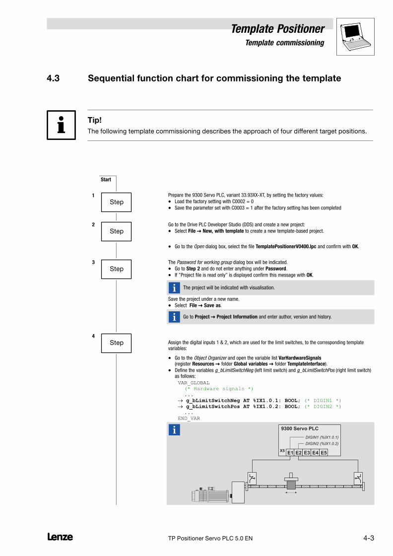
4.3 Sequential function chart for commissioning the template
Tip!
The following template commissioning describes the approach of four different target positions.
Start
1
StepPrepare the 9300 Servo PLC, variant 33.93XX−XT, by setting the factory values:
� Load the factory setting with C0002 = 0
� Save the parameter set with C0003 = 1 after the factory setting has been completed
2
StepGo to the Drive PLC Developer Studio (DDS) and create a new project:
� Select File � New, with template to create a new template−based project.
� Go to the Open dialog box, select the file TemplatePositionerV0400.lpc and confirm with OK.
3
StepThe Password for working group dialog box will be indicated.
� Go to Step 2 and do not enter anything under Password.
� If "Project file is read only" is displayed confirm this message with OK.
The project will be indicated with visualisation.
Save the project under a new name.
� Select File � Save as.
Go to Project � Project Information and enter author, version and history.
4
Step Assign the digital inputs 1 & 2, which are used for the limit switches, to the corresponding templatevariables:
� Go to the Object Organizer and open the variable list VarHardwareSignals(register Resources � folder Global variables � folder TemplateInterface).
� Define the variables g_bLimitSwitchNeg (left limit switch) and g_bLimitSwitchPos (right limit switch)as follows:
VAR_GLOBAL (* Hardware signals *) ... � g_bLimitSwitchNeg AT %IX1.0.1: BOOL; (* DIGIN1 *) � g_bLimitSwitchPos AT %IX1.0.2: BOOL; (* DIGIN2 *) ... END_VAR
E1 E2 E3 E4
9300 Servo PLC
X5E5
DIGIN1 (%IX1.0.1)
DIGIN2 (%IX1.0.2)
4 Template commissioning
Template Positioner
4−4 LTP Positioner Servo PLC 5.0 EN
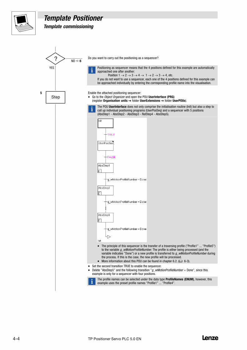
? Do you want to carry out the positioning as a sequencer?NO � 6
YES
Positioning as sequencer means that the 4 positions defined for this example are automaticallyapproached one after another:
Position 1 � 2 � 3 � 4 � 1 � 2 � 3 � 4, etc.
If you do not want to use a sequencer, each one of the 4 positions defined for this example canbe approached individually by entering the corresponding profile name into the visualisation.
5
StepEnable the attached positioning sequencer:
� Go to the Object Organizer and open the POU UserInterface (PRG)(register Organisation units � folder UserExtensions � folder UserPOUs).
The POU UserInterface does not only comprise the initialisation routine (Init) but also a step tocall up individual positioning programs (UserPosSeq) and a sequencer with 5 positions(AbsStep1 − AbsStep2 − AbsStep3 − RelStep4 − AbsStep5).
� The principle of this sequencer is the transfer of a traversing profile ("Profile1" ... "Profile5")to the variable g_wMotionProfileNumber. The profile is either being processed (and thevariable indicates "Done") or a new profile is transferred to g_wMotionProfileNumber duringthe process. If this is the case, the new profile will be processed.
� More information about this POU can be found in chapter 6.2. (� 6−3).
� Set the second transition TRUE to enable the sequencer.
� Delete "AbsStep5" and the following transition "g_wMotionProfileNumber = Done", since thisexample is only for a sequencer with four positions.
The profile names can be selected under the data type ProfileNames (ENUM), however, thisexample uses the preset profile names "Profile1" ... "Profile4".
Template Positioner4 Template commissioning
4−5L TP Positioner Servo PLC 5.0 EN
6
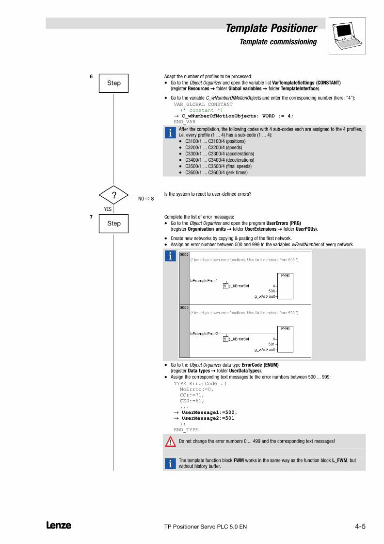
StepAdapt the number of profiles to be processed:
� Go to the Object Organizer and open the variable list VarTemplateSettings (CONSTANT)(register Resources � folder Global variables � folder TemplateInterface).
� Go to the variable C_wNumberOfMotionObjects and enter the corresponding number (here: "4"):
VAR_GLOBAL CONSTANT (* constant *) � C_wNumberOfMotionObjects: WORD := 4; END_VAR
After the compilation, the following codes with 4 sub−codes each are assigned to the 4 profiles,i.e. every profile (1 ... 4) has a sub−code (1 ... 4):
� C3100/1 ... C3100/4 (positions)
� C3200/1 ... C3200/4 (speeds)
� C3300/1 ... C3300/4 (accelerations)
� C3400/1 ... C3400/4 (decelerations)
� C3500/1 ... C3500/4 (final speeds)
� C3600/1 ... C3600/4 (jerk times)
? Is the system to react to user−defined errors?NO � 8
YES
7
StepComplete the list of error messages:
� Go to the Object Organizer and open the program UserErrors (PRG)(register Organisation units � folder UserExtensions � folder UserPOUs).
� Create new networks by copying & pasting of the first network.
� Assign an error number between 500 and 999 to the variables wFaultNumber of every network.
� Go to the Object Organizer data type ErrorCode (ENUM)(register Data types � folder UserDataTypes).
� Assign the corresponding text messages to the error numbers between 500 ... 999:
TYPE ErrorCode :( NoError:=0, CCr:=71, CE0:=61, ... � UserMessage1:=500, � UserMessage2:=501 ); END_TYPE
Do not change the error numbers 0 ... 499 and the corresponding text messages!
The template function block FWM works in the same way as the function block L_FWM, butwithout history buffer.

4 Template commissioning
Template Positioner
4−6 LTP Positioner Servo PLC 5.0 EN
8
StepCompile the project:
� Press the function key <F11> or select Project � Compile all.
? Did errors occur?NO � 10
YES
9
StepCarry out an error analysis:
� Press the function key <F4> or select Edit � Next fault.
� 9
10
StepSave the project:
� Press the key combination <Strg>+<S> or select File � Save.
If not happened before, go to Project � Project Information and enter author, version andhistory.
11
StepLog in:
� Press the key combination <Alt>+<F8> or select Online � Log in.
� Confirm the question "Do you want to load the new program?" with Yes.
Please observe the following:
A new program download overwrites the code settings with the initialisation values defined inthe Instance parameter manager!
Initialisation values available after the new program download are selected as follows:
� Go to the Object Organizer and open the Code initialisation values (register Resources).
� Enter the settings for the corresponding codes.
� Save the project and log in.
� Save the parameter set with C0003 = 1 after log in.
Codes can be saved as described in the following:
� Initialise the codes in the Instance parameter manager.
� Use GDC/GDC easy to create a parameter set file with your settings.
12
StepEnter the motor type and the max. motor speed:
� Use the Parameter monitor (Object Organizer/register Resources) and select the folderMotor/feedback system � Motor settings.
� Select the motor type under C0086.
� Enter the max. motor speed under C0011.
– Use the rated motor speed as max. motor speed. The data can be read from the motornameplate.
13
StepSettings for the feedback system:
� Use the Parameter monitor (Object Organizer/register Resources) and select the folderMotor/feedback system � Feedback systems.
� Select the feedback system under C0025.
Use C3000 and C3001 to adapt the motor and encoder mounting position.

Template Positioner4 Template commissioning
4−7L TP Positioner Servo PLC 5.0 EN
14
StepSelect the system parameters:
� Use the Parameter monitor (Object Organizer/register Resources) and select the folder IndividualIEC1131 codes � BasicParameter.
� Enter the gear factor for the optional feedback system under C1200 and C1201.
� Enter the gear factor for the motor gearbox under C1202 and C1203.
� Enter the feed constant under C1204.
The feed constant defines the distance traversed while one revolution at the gearbox output.
Example:
� Gear factor for the optional feedback system:Motor speed/encoder speed = 5.1432 � C1200/C1201 = 51432/10000
� Gear factor of the motor gearbox:Motor speed/speed = 58.667 � C1202/C1203 = 58667/1000
� Feed constant:One revolution at the gearbox output side corresponds to a distance of 5.023 mm.� [unit] = 1 mm � Feed constant = 5.023 [unit]� [unit] = 1 cm � Feed constant = 0.5023 [unit]
? Do you want to approach the home position by means of homing?NO � 16
YES
The measuring system in the machine is selected by means of homing and the zero position isset within the possible traversing range. The zero position is found by a home signal and thecorresponding offset selections.
Possible home signals:
� Marker pulse (signal edge of the encoder system, one per motor revolution)
� Touch probe (signal edge at input E4)
� User signal (signal edge through the variable g_bHomePositionSet)
� Limit switch (negative signal edge through the variable g_bLimitSwitchNeg org_bLimitSwitchPos)
� Reaching a defined motor torque value (code C3008)
Homing/setting of home position:
� Homing means that the drive traverses according to a certain mode and independently findsthe home position.
� The home position can also be set (instead of homing), i.e. the home position is set while thedrive is at standstill.

4 Template commissioning
Template Positioner
4−8 LTP Positioner Servo PLC 5.0 EN
15
StepSelect the homing parameters:
� Use the Parameter monitor (Object Organizer/register Resources) and select the folder IndividualIEC1131 codes � BasicParameter.
� Enter the offset in [unit] under C3011. The offset indicates the travel path between homing pointand zero position.
� Enter the offset in [unit] under C3012. The offset indicates the distance between homing point andzero position.
The machine position where the home signal occurs is known as home position.
The zero position of the machine can be determined by two different offset entries (measuredfrom the home position):
� Zero position offset with traversing of the drive by offset in C3011 (with C3012 = 0):
� �
�C3011
0
� Home position
� Zero position
� Drive traverses the offset in C3011from the home position
� Zero position offset without traversing of the drive by offset in C3012 (with C3011 = 0):
� �
� C3012
0
� Home position
� Zero position
� Drive stops at home position, C3012 determines the distance to the zeroposition.
It is also possible to combine the two offset entries! (C3011 � 0 and C3012 � 0)

Template Positioner4 Template commissioning
4−9L TP Positioner Servo PLC 5.0 EN
15
Step(continued)
� Enter the speed in [unit]/s which can be reached during homing under C3013.
� Enter the acceleration in [unit]/s2 which defines the acceleration and deceleration ramp underC3014.
Example:
With a homing speed of 360 [unit]/s under C3013 to be reached within 0.5 s, the value underC3014 is 720 [unit]/s2:
720�[unit]/s2 �
360�[unit]/s
0.5�s
� Check whether the wanted acceleration is possible.
� Ensure that the speed set under C3013 is not too high and the limit switches are not passed.
� 17
� Use the Parameter monitor (Object Organizer/register Resources) and select the folder IndividualIEC1131 codes � BasicParameter.
� Select mode 11 ("<_Ln_>_TP") under C3010 for homing.
Symbols for code C3010:
> Movement in positive direction
< Movement in negative direction
Lp Limit switch positive − limit switch in positive direction
Ln Limit switch negative − limit switch in negative direction
Rp Refmark positive − positive edge of home switch
Rn Refmark negative − negative edge of home switch
TP Touch probe edge of input E4
MP Marker pulse − zero pulse edge of motor (one per motor revolution)
Mlim Motor torque limitation (C3008)
Homing mode 11 with "<_Ln_>_TP" means for this example:
1. Movement to the left (<)
2. Movement to the left limit switch (Ln)
3. Change of direction (>)
4. Movement to the right to the touch probe initiator (TP signal at input E4).
16
StepSelect the homing parameters:
� Enter the offset in [unit] under C3012. The offset indicates the distance between homing point andzero position.
Offset entries: see information about step 15.
� Check whether the acceleration for manual homing (C3021) is possible with the motortorque.
� Ensure that the speed for manual homing set under C3020 is not too high and the limitswitches are not passed.
Speed/acceleration value: see information about step 15.

4 Template commissioning
Template Positioner
4−10 LTP Positioner Servo PLC 5.0 EN
17
StepSelect the software limit positions (measured from the zero position):
� Use the Parameter monitor (Object Organizer/register Resources) and select the folder IndividualIEC1131 codes � BasicParameter.
� Enter the positive software limit position under C3040.
� Enter the negative software limit position under C3041.
Software limit positions are positions or distances measured from the zero position in positiveand negative direction. They define the limits of a measuring system determined after homing.
� �
C3041
0
C3040
� Negative software limit position
� Positive software limit position
The software limit positions need not be necessarily positive and negative. It is also possible toselect two positive or negative software limit positions.
18
StepSelect the parameters for manual homing:
� Enter the speed in [unit]/s which can be reached during manual homing under C3020.
� Enter the acceleration ramp in [unit]/s2 under C3021.
� Enter the deceleration ramp in [unit]/s2 under C3022.
Manual homing means to rotate the drive in negative or positive direction through a manualhoming signal. Manual homing is stopped by taking back the manual homing signal or a systemlimit (limit switch, software limit position).
Example:
With a manual homing speed of 360 [unit]/s under C3020 to be reached within 0.5 s, the valueunder C3021 is 720 [unit]/s2:
720�[unit]/s2 �
360�[unit]/s
0.5�s
� Check whether the wanted acceleration is possible.
� Ensure that the speed set under C3020 is not too high and the limit switches are not passed.
19
StepSelect the following error warning limit and the following error limit:
� Enter the following error warning limit in [unit] which activates a message in the visualisation underC3030.
� Enter the following error limit in [unit] which stops the machine under C3031.
A following error is the difference between position setpoint and actual position which occurs ifthe drive is slower than the position setpoint because of its moment of inertia.
Following errors must be compensated or reduced because they can cause excessive transientreactions.
20
StepStart the PLC:
� Press the function key <F5> or select Online � Start.

Template Positioner4 Template commissioning
4−11L TP Positioner Servo PLC 5.0 EN
21
StepSelect the maximum speed for the system:
� Use the Parameter monitor (Object Organizer/register Resources) and select the folder IndividualIEC1131 codes � BasicParameter.
� Read the value of C3060.This value defines the maximum speed of the system and because of a program−internal calculationit will only be indicated in the Parameter monitor when the PLC has been started.
� Enter the value indicated in C3060 under C1240.
Do not enter a value under C1240 higher than the value indicated under C3060.
If you enter a value lower than the value indicated in C3060 under C1240 all speed valuesdetermined for the positioning profiles will be limited by this value.
22
StepSelect the maximum acceleration for the system:
� Enter the maximum permissible acceleration value in [unit]/s2 under C1250.
The acceleration value is calculated from the maximum motor torque and the moment of inertiato be accelerated:
Maximum�acceleration �
Maximum�motor�torque
Total�moment�of�inertia
Rough values can be set according to the maximum speed set under C1240. If the machineaccelerates to maximum speed within the selected time C1250 is:
C1250 � C1240
Time from 0 [unit]/s to C1240
All acceleration and deceleration values selected for the positioning profiles are limited byC1250.
23
StepPermanently save the parameter set with C0003 = 1 in the PLC.
Please note:
A repeated program download overwrites the code settings with the initialisation values!
24
StepWrite the positioning profiles:
� Use the Parameter monitor (Object Organizer/register Resources) and select the folder IndividualIEC1131 codes � POUPositioning.
� Enter the positions of profiles 1 ... 4 in [unit] under C3100/1 ... 4.
� Enter the speeds of profiles 1 ... 4 in [unit]/s under C3200/1 ... 4.
� Enter the accelerations of profiles 1 ... 4 in [unit]/s2 under C3300/1 ... 4 .
� Enter the decelerations of profiles 1 ... 4 in [unit]/s2 under C3400/1 ... 4 .
� Close the Parameter monitor.
Reminder:
� In step 6 you have defined four profiles (1 ... 4) via C_wNumberOfMotionObjects.
� With the data type ProfileNames (ENUM) you have assigned profile names to the profiles"Profile1" ... "Profile4".
The assignment Profile3:=3 means, e.g.:
� "Profile3" takes place 3 in data type ProfileNames (ENUM).� "Profile3" is written by the corresponding sub−code 3 of C3100 ... C3600.
25
StepOpen the user interface in the visualisation:
� Go to the Object Organizer/register Visualisation and select the visualisation VisOperation.
? Do you want to approach the home position by means of homing?NO � 27
YES

4 Template commissioning
Template Positioner
4−12 LTP Positioner Servo PLC 5.0 EN
26
StepStart homing by clicking the start button under homing in the visualisation.
(Here homing uses mode 11, see step 16)
� 28
� The template state "Homing" is displayed.
� The drive is carrying out a homing process.
� The template state "StandBy" will be indicated as soon as homing is completed.
Homing in mode 11 (<_Ln_>_TP):
1. Movement to the left (<)
� �
� Left limit switch (connected to E1)
� Touch probe initiator (connected to E4)
2. Movement to the left limit switch (Ln)
�
3. Change of direction (>)
4. Movement to the right to the touch probe initiator (TP signal at input E4).
�
If the template state "Trouble" is indicated in the visualisation, an error has been detected.
� Click Error Reset to acknowledge the error.
� Internal errors (TRIP) cannot be directly acknowledged via Error Reset. They can only bereset after a TRIP reset.

Template Positioner4 Template commissioning
4−13L TP Positioner Servo PLC 5.0 EN
27
StepSet the home position manually by clicking the load button under home set in the visualisation.
28
StepManual homing:
� Click the jog negative button under manual jog in the visualisation.� The drive moves in negative direction at manual traversing speed.
� Click the jog positive button under manual jog in the visualisation.� The drive moves in positive direction at manual traversing speed.
The template state "ManualJog" will be indicated as long as manual homing is active.
29
StepStart the positioning sequencer:
� Ensure that "absolute" (for absolute positioning) is entered under positioning control, input fieldposition mode in the visualisation.
� Click the start button under positioning control.� The template state "Positioning" is displayed.� The positions of the four profiles are approached one after the other following the selectionsmade in step 25. After profile 4 has been used, the process starts again with profile 1.
� Click the stop button under positioning control.� The drive decelerates along the ramp of the currently active profile to standstill.� The template state "StandBy" is displayed.
If the positioning values are not within the measuring system TRIP will be set:
� The template state "Trouble" is displayed and QSP is indicated.
� Correct the corresponding target position and acknowledge the error (ErrorReset).
If you have not programmed a sequencer it is also possible to enter the profile name underpositioning control, input field profile name.
� The corresponding positioning profile will be processed and the input field will display"Active" or "Done" as soon as the target position has been reached.
� It is possible to enter a new profile into the input field while "Active" is still being displayed.The approach of the current target position will be stopped and the new profile data will beused immediately.
END
Tip!
You have learned about the basic functions of the Template Positioner:
� Setting of main machine parameters
� Setting of defined system parameters
� Setting of homing parameters
� Selection of the measuring system
� Selection of movement profiles
� Homing by means of visualisation
� Manual homing by means of visualisation
� Programming of a simple sequencer
� Processing of a programmed sequencer by means of visualisation

4 Template commissioning
Template Positioner
4−14 LTP Positioner Servo PLC 5.0 EN

Template Positioner5 The "Positioning" status machine
5−1L TP Positioner Servo PLC 5.0 EN
5 The "Positioning" status machine
The following figure shows the status machine which is the basis for the individual function modulesof the template.
ManualJog
StandardPositioning
TouchProbePositioning
TemplateControl
Homing
ExitM
anua
l
Enter
Man
ual
EnterTrouble
ExitTrouble
EnterHom
ing
ExitHom
ing
ExitP
osition
ing
Enter
Position
ing
Start
StandBy
Init
Init Ok
Positioning
Homing
Trouble
ManualJog
ExternalSetValuePositioning
StaticHomePositionSet
ChangeProfileInterface
ChangeProfileInterface ChangeProfileInterface
PosFunctions
PositionCorrection
OverchangePositioning
OverridePositioning
PositionTeach
ChangeProfileInterface
Fig. 5−1 "Positioning" status machine
The status machine comprises different statuses and defined status changes, so−called transitions.
� There is always only one status active. This makes diagnostics easier in case of an error.
� A status changes into another if the condition for the corresponding transition is met.Example:The change from "StandBy" to "Positioning" can only be carried out if the condition for the"EnterPositioning" transition is met. If the status is to change back to "StandBy" the conditionfor the "ExitPositioning" transition must be fulfilled.
� The function modules of the template are assigned to different statuses to ensure that specificfunctions cannot be activated at the same time. Manual homing cannot be carried out if positioning or homing is active.

5 The "Positioning" status machine
Template Positioner
5−2 LTP Positioner Servo PLC 5.0 EN
5.1 Short status description
Status "Init"
This status is activated after the PLC has been started.
The following actions are executed in "Init":
� Identification and setting of the feedback systems for speed and position detection.
� Checking of the home position if multi−turn encoders/resolvers are used as absolute valueencoders.
� Calculation of the internal values for the positioning control.
Status "StandBy"
This status is of central importance since it is always activated when a status changes into another.If you change from "Trouble" to "ManualJog", "StandBy" will be active for one cycle.
The following actions are executed in "StandBy":
� Checking and calculation of the maximum speed indicated in code 3060.
� Calculation of the machine parameters, maximum travel path and internal values for homing.
� Calculation/acceptance of all monitoring limit values,e.g.:
– Following error warning limit
– Following error limit
– Calculation of the positioning window for the message "Target position reached"(g_bInTarget)
– Calculation of the time setting for the message "Dwell time over" (g_bDwellTime)
� Enabling of the functions PositionTeach and ExternalSetValuePositioning.
� Setting of the home position by using the function StaticHomePositionSet.
Status "Trouble"
This status is activated if the operating system of the PLC or user program sends an error message.
The following actions are executed in "Trouble":
� Display of the current error.
� Enabling of the reset mechanism for user errors.
Status "ManualJog"
This status enables manual traversing of the drive system (manual homing/jog control).
The following actions are executed in "ManualJog":
� Creation of movement profiles for the function ManualJog (manual homing).
� Evaluation of the traversing range limit switches during manual homing.
� Retracting from the traversing range limit switch.

Template Positioner5 The "Positioning" status machine
5−3L TP Positioner Servo PLC 5.0 EN
Status "Homing"
Setting or automatic finding of the home position.
The following actions are executed in "Homing":
� Creation of movement profiles for the function Homing.
� Evaluation of the traversing range limit switches during homing.
Status "Positioning"
This status is used for the core function of the template, the positioning of the drive system.
� Positioning commands are only executed in "Positioning".
� A status change (e.g. as a result of an error or initiated by the user) leads to an immediatequick stop of the drive system.
The following actions are executed in "Positioning":
� Creation of movement profiles for the positioning functions:
– StandardPositioning
– TouchProbePositioning
– OverridePositioning
– OverchangePositioning
� Calculation of the profile parameters during writing by means of the functionChangeProfileInterface.
Parallel process "PosFunctions"
This status is always active. It is independent of the status control transitions.
The following actions are executed in "PosFunctions":
� Calculation of the monitoring functions (software limit positions, hardware limit positions,following errors, etc.).
� General template control functions.
� Calculations for the visualisations.

5 The "Positioning" status machine
Template Positioner
5−4 LTP Positioner Servo PLC 5.0 EN
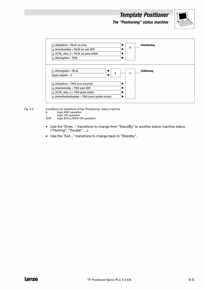
5.2 Conditions for status changes (transitions)
The below figure shows the conditions to be fulfilled for the individual transitions in the form of logicoperations:
g_bGlobalError = TRUE (error occurred) ��1
EnterTrouble
TRIP active �
g_bErrorReset = TRUE (error acknowledged) �&
ExitTrouble
No current error �
g_bGlobalError = FALSE (no error) �&
EnterPositioning
g_bUserQuickstop = FALSE (no user QSP) �
g_DCTRL_bImp_b = FALSE (no pulse inhibit) �
g_bPositioningEnable = TRUE �
g_bGlobalError = TRUE (error occurred) ��1
ExitPositioning
g_bUserQuickstop = TRUE (user QSP) �
g_DCTRL_bImp_b = TRUE (pulse inhibit) �
g_bPositioningEnable = FALSE �&
Speed setpoint = 0 �
g_bLimitSwitchPos = TRUE �XOR & � &
EnterManual
g_bLimitSwitchNeg = TRUE �
g_bReleaseLimitSwitch= TRUE �
g_bManualJogPos = TRUE �
g_bManualJogNeg = TRUE �
g_bGlobalError = FALSE (no error) �
g_bUserQuickstop = FALSE (no user QSP) �
g_DCTRL_bImp_b = FALSE (no pulse inhibit) �
g_bManualJogPos = FALSE �& �1
ExitManual
g_bManualJogNeg = FALSE �
g_bReleaseLimitSwitch = FALSE �
g_bLimitSwitchPos = TRUE �
g_bLimitSwitchNeg = TRUE �
Speed setpoint = 0 �
g_bGlobalError = TRUE (error occurred) �
g_bUserQuickstop = TRUE (user QSP) �
g_DCTRL_bImp_b = TRUE (pulse inhibit) �
Template Positioner5 The "Positioning" status machine
5−5L TP Positioner Servo PLC 5.0 EN
g_bGlobalError = FALSE (no error) �&
EnterHoming
g_bUserQuickstop = FALSE (no user QSP) �
g_DCTRL_bImp_b = FALSE (no pulse inhibit) �
g_bHomingStart = TRUE �
g_bHomingStart = FALSE �& �1
ExitHoming
Speed setpoint = 0 �
g_bGlobalError = TRUE (error occurred) �
g_bUserQuickstop = TRUE (user QSP) �
g_DCTRL_bImp_b = TRUE (pulse inhibit) �
g_bHomePositionAvailable = TRUE (home position known) �
Fig. 5−2 Conditions for transitions of the "Positioning" status machine& logic AND operation� logic OR operationXOR logic EXCLUSIVE−OR operation
� Use the "Enter..." transitions to change from "StandBy" to another status machine status("Homing", "Trouble", ...).
� Use the "Exit..." transitions to change back to "Standby".

5.3 Status "StandBy"
Template PositionerStates & Functions
5−6 LTP Positioner Servo PLC 5.0 EN
5.3 Status "StandBy"
With �Standby" the drive remains in its current position.
The following template functions can be executed in this status:
Function Info
ExternalSetValuePositioning Direct transfer of external setpoints to the motor control � 5−7
PositionTeach Saving of the actual position � 5−9
StaticHomePositionSet Manual setting/resetting of the home position � 5−10

Template PositionerStates & Functions
5.3.1 Function "ExternalSetValuePositioning"
5−7L TP Positioner Servo PLC 5.0 EN
5.3.1 Function "ExternalSetValuePositioning"
This template function is used to control a motor independently of the positioning control by externalsetpoint entries.
� The function is only possible with "StandBy".
Stop!
The software limit positions are deactivated during external setpoint motor control. If they arepassed, you will not receive an error message.
Parameter
Inputs Outputs
g_bExtSetValuesEnable
ExternalSetValuePositioning
g_nExtMSet_a
g_nExtNSet_a
g_dnExtDeltaPos_p
MCTRL
nset
�pos
Motorcontrol
Mset
� Inputs
Identifiers Data type Access Info/possible settings
g_bExtSetValuesEnable Bool R / W Changeover to external setpoints
TRUE The external setpoints are directly transferred to the motorcontrol:
� g_nExtMSet_a � nMSet_a
� g_nExtNSet_a � nNSet_a
� g_dnExtDeltaPos_p � dnDeltaPos_p
g_nExtMSet_a Integer R / W External setpoint for torque precontrol
g_nExtNSet_a Integer R / W External setpoint for the setpoint speed
g_dnExtDeltaPos_p Integer R / W External setpoint for the position difference

5.3.1 Function "ExternalSetValuePositioning"
Template PositionerStates & Functions
5−8 LTP Positioner Servo PLC 5.0 EN
Changeover to external setpoints
Set g_bExtSetValuesEnable to TRUE to change from positioning control to external setpoint control:
nset Motorcontrol
Mset
Positioning control
External set values
g_bExtSetValuesEnable
g_nExtMSet_a
g_nExtNSet_a
g_dnExtDeltaPos_p
v
t
C3000<>C3001
g_nMAdd_a
g_nNAdd_a
During external setpoint control, the positioning control follows the position changes made. Afterdeactivation of the external setpoint control, it can thus continue precise positioning provided thatthe max. traversing range of (231 − 1) increments (2147483647 increments) is not exceeded.
If motor and encoder mounting position (C3000/C3001) are not identical in the application, this willbe automatically considered when using external setpoints for speed and following error. Externaltorque setpoints must be inverted manually.
The speed/torque setpoints can also be influenced via the inputs g_nNAdd_a and g_nMAdd_a.
� If the max. traversing range is exceeded, a path integrator overflow will occur.

Template PositionerStates & Functions
5.3.2 Function "PositionTeach"
5−9L TP Positioner Servo PLC 5.0 EN
5.3.2 Function "PositionTeach"
With this template function you can save the current position of the machine part in a profile.
� In this way, the individual target positions can be taught in turns with the function ManualJog("Teach in").
� The function is only possible with "StandBy".
Parameter
Inputs Outputs
PositionTeach
�
Profile n
Profile ...
Profile 2
Profile 1
v
t
position teach
actualposition
g_bPositionTeach
g_wTeachProfileNumber
� Inputs
Identifiers Data type Access Info/possible settings
g_bPositionTeach Bool R / W Saving of actual positions
FALSE TRUE Actual position is saved in g_wTeachProfileNumber.
� Precondition: g_bHomingDone = TRUEand g_bHomePositionAvailable = TRUE
g_wTeachProfileNumber ProfileNames R / W Profile name for actual position
� Indicates in which profile the actual position is saved if g_bPositionTeach= TRUE.
Display�Done"
The actual position has been saved in the correspondingprofile.
Tip!
The machine part can be moved in different ways into the teach position to be saved:
� With the function ManualJog the desired position can be approached through jog control.
� With controller inhibit the machine part can be manually moved into the desired position.
� With the function ExternalSetValuePositioning the desired position can be approached byselecting external setpoints.
Saving of the actual position ("teach in")
By setting g_bPositionTeach to TRUE, the actual position will be saved in the profileg_wTeachProfileNumber.

5.3.3 Function "StaticHomePositionSet"
Template PositionerStates & Functions
5−10 LTP Positioner Servo PLC 5.0 EN
5.3.3 Function "StaticHomePositionSet"
This template function is used to set the home position during commissioning.
� The home position can be set in "StandBy".
� If the home position has been set, the tool position is permanently saved and can be retrievedeven after mains disconnection. (This only applies if an absolute value encoder is used.)
� Setting of the home position only has to be repeated if commissioning is repeated, in the eventof servicing (e.g. replacement of drive components) or if the home position has been deletedas a result of a corresponding traversing command.
Parameter
Inputs Outputs
g_bHomePositionSet
C3002
C3012
no position change while power off
offset
StaticHomePositionSet
g_bHomePositionReset g_bHomingDone
C3012
0-Position
100 200 3000
g_bHomePositionAvailable
g_bHomingBusy
� Inputs
Identifiers Data type Access Info/possible settings
g_bHomePositionSet Bool R / W Acceptance of the home position
FALSE TRUE Offset of the reference measuring system selected under codeC3012 is accepted.
g_bHomePositionReset Bool R / W Reset of home position
TRUE � Output g_bHomingDone is reset to FALSE.
� Status "Home position known" is reset(g_bHomePositionAvailable = FALSE).
Template PositionerStates & Functions
5.3.3 Function "StaticHomePositionSet"
5−11L TP Positioner Servo PLC 5.0 EN
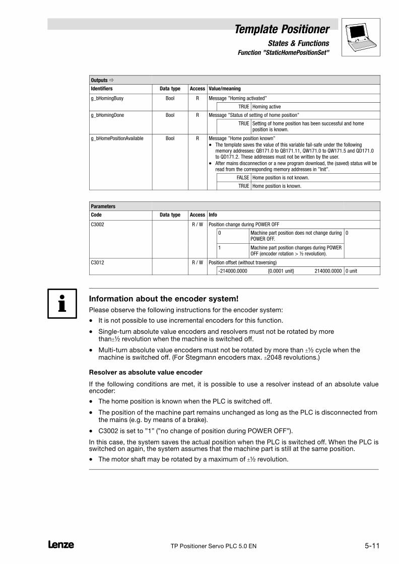
Outputs �
Identifiers Data type Access Value/meaning
g_bHomingBusy Bool R Message "Homing activated"
TRUE Homing active
g_bHomingDone Bool R Message "Status of setting of home position"
TRUE Setting of home position has been successful and homeposition is known.
g_bHomePositionAvailable Bool R Message "Home position known"
� The template saves the value of this variable fail−safe under the followingmemory addresses: QB171.0 to QB171.11, QW171.0 to QW171.5 and QD171.0to QD171.2. These addresses must not be written by the user.
� After mains disconnection or a new program download, the (saved) status will beread from the corresponding memory addresses in "Init".
FALSE Home position is not known.
TRUE Home position is known.
Parameters
Code Data type Access Info
C3002 R / W Position change during POWER OFF
0 Machine part position does not change duringPOWER OFF.
0
1 Machine part position changes during POWEROFF (encoder rotation > ½ revolution).
C3012 R / W Position offset (without traversing)
−214000.0000 {0.0001 unit} 214000.0000 0 unit
Information about the encoder system!
Please observe the following instructions for the encoder system:
� It is not possible to use incremental encoders for this function.
� Single−turn absolute value encoders and resolvers must not be rotated by morethan½ revolution when the machine is switched off.
� Multi−turn absolute value encoders must not be rotated by more than ½ cycle when themachine is switched off. (For Stegmann encoders max. 2048 revolutions.)
Resolver as absolute value encoder
If the following conditions are met, it is possible to use a resolver instead of an absolute valueencoder:
� The home position is known when the PLC is switched off.
� The position of the machine part remains unchanged as long as the PLC is disconnected fromthe mains (e.g. by means of a brake).
� C3002 is set to "1" ("no change of position during POWER OFF").
In this case, the system saves the actual position when the PLC is switched off. When the PLC isswitched on again, the system assumes that the machine part is still at the same position.
� The motor shaft may be rotated by a maximum of ½ revolution.

5.3.3 Function "StaticHomePositionSet"
Template PositionerStates & Functions
5−12 LTP Positioner Servo PLC 5.0 EN
Setting of the home position
The home position is set as follows:
1. Measure the distance between the machine part to be positioned and its zero position (homeposition).
2. Enter this value under code C3012 in fixed−point format in [unit].
3. Set g_bHomePositionSet from FALSE to TRUE to accept the value and transmit the homeposition to the PLC.
Note!
The function "ExternalSetValuePositioning" must be deactivated for setting the home position.
Status "Home position known"
If the home position has been set the output g_bHomingDone is set to TRUE. As soon as the homeposition is known, the output g_bHomePositionAvailable is also set to TRUE.
Note!
Please note that the home position will get lost and the status "Home position known" reset whencertain positioning processes are started (e.g. constant traversing and all positioning modes in whichthe path integrators are reset) or when machine parameters are changed.
Status identification after power−on
When the PLC is switched on again, the system checks in "Init" if the home position is known andsaves the current status in the variable g_bHomePositionAvailable:
� g_bHomePositionAvailable = TRUE �Home position is known.
� g_bHomePositionAvailable = FALSE �Home position is not known.
Status reset
The status "Home position known" can be reset by setting g_bHomePositionReset to TRUE.
� The output g_bHomingDone and the status variable g_bHomePositionAvailable are reset toFALSE.

Template PositionerStates & Functions
5.4 Status "Homing"
5−13L TP Positioner Servo PLC 5.0 EN
5.4 Status "Homing"
In "Homing" you can carry out a homing process to show the position of the tool or material in thePLC and identify the zero position (home position).
The following function is used for homing:
Function Info
Homing Homing
� The tool is actively moved to find a homing mark and traverse to a defined position.
� 5−14
Tip!
� Homing is mainly used for systems with feedback via incremental encoders, resolvers orsingle−turn absolute value encoders, where the home position gets lost when the supplyvoltage is switched off.
� In general, setting of home positions is only carried out during commissioning or in theevent of servicing (e.g. replacement of drive components) and is only used for systems withfeedback via absolute value encoders. The function StaticHomePositionSet is available in"StandBy" for setting the home position. � 5−10
Condition (transition) for a status change to "Homing"
g_bGlobalError = FALSE (no error) �&
EnterHoming
g_bUserQuickstop = FALSE (no user QSP) �
g_DCTRL_bImp_b = FALSE (no pulse inhibit) �
g_bHomingStart = TRUE �
� A status change to "Homing" is only possible in "StandBy"!
Condition (transition) for changing back to "StandBy"
g_bHomingStart = FALSE �& �1
ExitHoming
Speed setpoint = 0 �
g_bGlobalError = TRUE (error occurred) �
g_bUserQuickstop = TRUE (user QSP) �
g_DCTRL_bImp_b = TRUE (pulse inhibit) �
g_bHomePositionAvailable = TRUE (home position known) �

5.4.1 Function "Homing"
Template PositionerStates & Functions
5−14 LTP Positioner Servo PLC 5.0 EN
5.4.1 Function "Homing"
This template function is used to carry out a homing process.The drive traverses in a pre−selectedmode to identify the zero position (home position) by means of a homing mark and transfers it to thedrive control. All position values refer to the home position.
� In general, "Homing" is carried out once after every power−on.
� The following internal signals of the PLC operating system can be used as home signals:
– Marker pulse (signal edge of the encoder system for the actual position value, one per motorrevolution)
– Touch probe (signal edge at the touch probe input)
� It is possible to define a preliminary stop position by means of a home switch. In this case, thehome position is the following zero position of the actual value encoder of the motor.
Parameter
Inputs Outputs
g_bHomingStart
g_bHomingMark
g_bHomingBusy
Homing
g_bHomingDone
C3010
g_bLimitSwitchNeg
g_bLimitSwitchPos
C3015
C3013
Offset (C3011, C3012)
0-Position
acceleration/deceleration
velocity
homing mode
C3011, C3012 offset
g_bHomePositionAvailable
no position change while power offC3002
TP
C3008, C3009 torque limit / time for homing mode 14 & 15
C3014
jerk time

Template PositionerStates & Functions
5.4.1 Function "Homing"
5−15L TP Positioner Servo PLC 5.0 EN
� Inputs
Identifiers Data type Access Info/possible settings
g_bHomingStart Bool R / W Homing start/stop
� Homing can only be started if the controller is enabled and TRIP is not active.
� If TRIP or controller inhibit are set during homing, homing must be started againafter TRIP reset or controller enable.
TRUE Homing start
FALSE Homing stop
g_bHomingMark Bool R / W Waiting for motor zero pulse signal
TRUE FALSE Starts waiting for the motor zero pulse signal during homing.
g_bLimitSwitchNeg Bool R / W Input for limit switch (negative)
FALSE Limit switch reached
g_bLimitSwitchPos Bool R / W Input for limit switch (positive)
FALSE Limit switch reached
Outputs �
Identifiers Data type Access Value/meaning
g_bHomingBusy Bool R Message "Homing activated"
TRUE Homing active
g_bHomingDone Bool R Status signal whether homing has been completed.
TRUE Homing has been completed or home position has beenmanually set through g_bHomePositionSet = TRUE.
g_bHomePositionAvailable Bool R Message "Home position known"
� The template saves the value of this variable fail−safe under the followingmemory addresses: QB171.0 to QB171.11, QW171.0 to QW171.5 and QD171.0to QD171.2. These addresses must not be written by the user.
� After mains disconnection or a new program download, the (saved) status will beread from the corresponding memory addresses in "Init".
FALSE Home position is not known.
TRUE Home position is known.
Parameters
Code Data type Access Info
Sub−code Possible settings Pre−setting
C3002 R / W Position change during POWER OFF
0 Machine part position does not change duringPOWER OFF
0
1 Machine part position changes during POWEROFF(encoder rotation > ½ revolution)
C3008 R / W Maximum motor torque during homing in [%] of maximum motor torqueMCTRL_wMmaxC57.
� Only relevant for homing mode 14 & 15.
0.00 {0.01 %} 100.00 10.00 %
C3009 R / W "Homing to fixed stop": Time in [ms] for which the maximum motor torque (C3008)may be active before it will be reduced and after which the home position will bedetermined (including the offset selection).
� Only relevant for homing mode 14 & 15.
0 {1 ms} 65535 100 ms

5.4.1 Function "Homing"
Template PositionerStates & Functions
5−16 LTP Positioner Servo PLC 5.0 EN
Parameters
Code InfoAccessData type
Sub−code Pre−settingPossible settings
C3010 Byte R / W Homing mode
0 >_Rn_MP 0
1 <_Rn_MP
2 >_Lp_<_Rn_MP
3 <_Ln_>_Rn_MP
4 >_Rp_<_Rn_MP
5 <_Rp_>_Rn_MP
6 >_Rn_>_TP
7 <_Rn_<_TP
8 >_TP
9 <_TP
10 >_Lp_<_TP
11 <_Ln_>_TP
12 >_Lp_<_Lp
13 <_Ln_>_Ln
14 >_Mlim
15 <_Mlim
Symbols for code C3010:
> Movement in positive direction
< Movement in negative direction
Lp Limit switch in positive direction( = positive edge; = negative edge)
Ln Limit switch in negative direction( = positive edge; = negative edge)
Rp Positive edge of home switch
Rn Negative edge of home switch
TP Touch probe edge of input E4
MP Zero pulse edge of the motor(one per motor revolution)
Mlim Motor torque limitation (C3008)
� When the last action listed is executed, the home position isset (e.g. zero pulse with "MP"), even if the drive continuestraversing.
� In all modes without "Lp" or "Ln" it is not possible to retractfrom the limit switch.
C3011 R / W Position offset (with traversing)
−214000.0000 {0.0001 unit} 214000.0000 0 unit
C3012 R / W Position offset (without traversing)
−214000.0000 {0.0001 unit} 214000.0000 0 unit
C3013 R / W Homing speed
0.0001 {0.0001 unit/s} 214000.0000 360 unit/s
C3014 R / W Acceleration/deceleration
0.0001 {0.0001 unit/s2} 214000.0000 720 unit/s2
C3015 R / W Jerk time
0.000 {0.001 s} 10.000 0 s
Note: The acceptance of new settings under C3010 ... C3015 requires a status change to "StandBy"!
Tip!
The [unit] is to be entered in fixed−comma format with 4 decimal positions, i.e. 1 [unit] 10000.

Template PositionerStates & Functions
5.4.1 Function "Homing"
5−17L TP Positioner Servo PLC 5.0 EN
Note!
Please ensure that the parameters for touch probe activation (pos./neg. edge) and touch probeselection are set in the PLC to make sure that the touch probe or zero pulse signal will be correctlyidentified during homing:
� for homing mode 0 ... 5: Touch probe selection via zero pulse
� for homing mode 6 ... 11: Touch probe selection via digital input
More information about touch probe parameter setting can be found in the PLC Manual.
Using the limit switch as a home switch
With homing modes 12 and 13 the corresponding limit switches will be used as reference switches.
v [rpm]
t [s]
�
vref
1
0t [s]
Fig. 5−3 Signal flow for a limit switch � also used as a reference switch.
Note!
If you want to use a limit switch as reference switch, the homing speed must be selected in a waythat the drive stops at the limit switch and reverses from there!
Assigning the digital inputs of the PLC to the limit switch/reference switch variables
The digital inputs of the PLC are assigned via their direct addresses to the corresponding inputvariables for the limit switch/reference switch signals.
Example:
� Left limit switch (negative) at digital input 1
� Reference switch at digital input 3
� Right limit switch (positive) at digital input 2
g_bLimitSwitchNeg AT %IX1.0.1: BOOL; (* = DIGIN1 *)g_bHomingMark AT %IX1.0.3: BOOL; (* = DIGIN3 *)g_bLimitSwitchPos AT %IX1.0.2: BOOL; (* = DIGIN2 *)

5.4.1 Function "Homing"
Template PositionerStates & Functions
5−18 LTP Positioner Servo PLC 5.0 EN
Offset entries for the selection of the zero position
The machine position where the home signal occurs is known as home position. The zero positionof the machine can be determined by two different offset entries (measured from the home position).
Note!
The acceptance of new offset entries requires a status change to "StandBy"!
Zero position offset with traversing of the drive
� Enter the offset in [unit] under C3011 which indicates the distance to be traversed betweenhome position and zero position:
� �
�C3011
0
Fig. 5−4 Offset entry under C3011 for traversing the drive by this offset (with C3012 = 0)� Home position (position of the home switch)� Zero position� Drive traverses the offset under C3011 from the home position
Zero position offset without traversing of the drive
� Enter the offset in [unit] under C3012 which indicates the distance between home position andzero position.
� �
� C3012
0
Fig. 5−5 Offset entry under C3012 without traversing the drive by this offset (with C3011 = 0)� Home position (position of the home switch)� Zero position� Drive stops at home position, C3012 determines the distance to the zero position.
Tip!
It is also possible to combine the offset entries! (C3011 � 0 and C3012 � 0).

Template PositionerStates & Functions
5.4.1 Function "Homing"
5−19L TP Positioner Servo PLC 5.0 EN
Example: Homing with a leadscrew drive (limited traversing range)
Settings:
� For the homing mode selected in this example "<_Ln_>_Ln", set C3010 (HomingMode) to"13".
� Assign the address of the negative limit switch to the variable g_bLimitSwitchNeg. (Seeexample on page 5−17.)
� Assign the address of the positive limit switch to the variable g_bLimitSwitchPos. (Seeexample on page 5−17.)
� Select the traversing speed under C3013.
� Select the acceleration/deceleration under C3014.
� Enter the target position after completion of homing as offset to the home position underC3011. The target position is the zero position of the machine.
Tip!
The parameters C3011 ... C3014 are entered in fixed−comma format with 4 decimal positions, i.e.for 1.0000 [unit] you have to enter "10000".
Offset (C3011)
�
�
�
�
100 200 300 400
MP
500 600
Fig. 5−6 Homing in mode 3 with a negative limit switch used as home switch� Home position (position of the limit switch)� Target position (zero position)� Traversing to negative limit switch� Traversing to target position
Functional sequence:
1. Homing is started by setting g_bHomingStart to TRUE.
2. During homing g_bHomingBusy = TRUE.
3. The drive traverses to the negative limit switch and reverses. �
4. Since the limit switch is also used as home switch, the preliminary stop position will be setwhen the drive leaves the limit switch, i.e. when the next zero pulse (MP) of the motor encoderis reached, the drive control will know the home position.
5. The drive continues traversing without interruption to the target position which has beendefined as offset to the home position under C3011. �
6. Homing is completed when the target position is reached and g_bHomingDone andg_bHomePositionAvailable are set to TRUE.

5.4.1 Function "Homing"
Template PositionerStates & Functions
5−20 LTP Positioner Servo PLC 5.0 EN
Example: Homing with a band drive (unlimited traversing range)
In applications with an unlimited traversing range (e.g. conveyor belts and rotary tables) homing iscarried out by means of a touch probe sensor.
Settings:
� For the homing mode selected in this example ">_Tp", set C3010 (HomingMode) to "8".
� Select the traversing speed under C3013.
� Select the acceleration/deceleration under C3014.
� Enter the target position after completion of homing as offset to the home position underC3011. The target position is the zero position of the machine.
Tip!
The parameters C3011 ... C3014 are entered in fixed−comma format with 4 decimal positions, i.e.for 1.0000 [unit] you have to enter "10000".
Offset (C3011)
100 200 300 400 500 600
TP
� �
� �
Fig. 5−7 Homing in mode 8� Position of the touch probe sensor� Target position (zero position)� Traversing in direction touch probe sensor� Traversing to target position
Functional sequence:
1. Homing is started by setting g_bHomingStart to TRUE.
2. During homing g_bHomingBusy = TRUE.
3. The drive traverses in positive direction. �
4. When the touch probe sensor is reached, the drive control knows the home position.
5. The drive continues traversing without interruption to the target position which has beendefined as offset to the home position under C3011. �
6. Homing is completed when the target position is reached and g_bHomingDone andg_bHomePositionAvailable are set to TRUE.
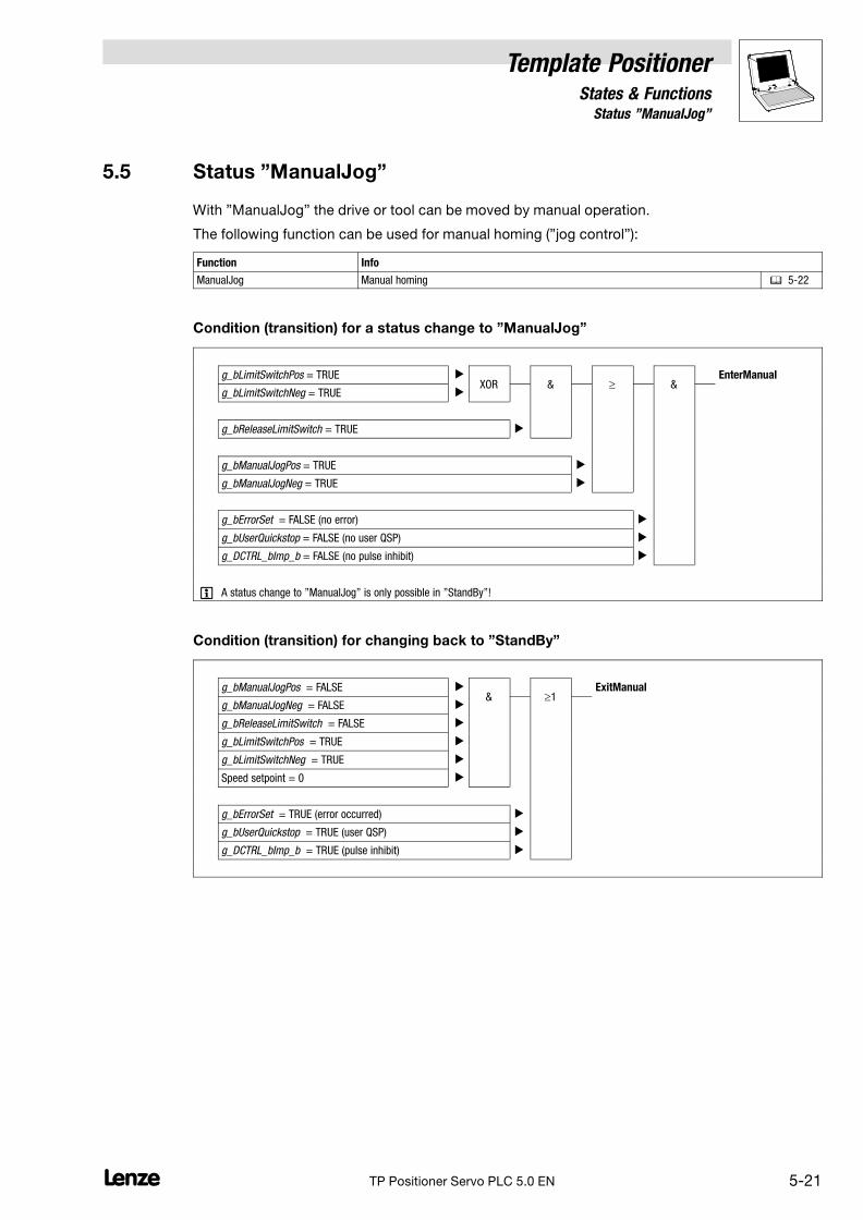
Template PositionerStates & Functions
5.5 Status "ManualJog"
5−21L TP Positioner Servo PLC 5.0 EN
5.5 Status "ManualJog"
With "ManualJog" the drive or tool can be moved by manual operation.
The following function can be used for manual homing ("jog control"):
Function Info
ManualJog Manual homing � 5−22
Condition (transition) for a status change to "ManualJog"
g_bLimitSwitchPos = TRUE �XOR & � &
EnterManual
g_bLimitSwitchNeg = TRUE �
g_bReleaseLimitSwitch = TRUE �
g_bManualJogPos = TRUE �
g_bManualJogNeg = TRUE �
g_bErrorSet = FALSE (no error) �
g_bUserQuickstop = FALSE (no user QSP) �
g_DCTRL_bImp_b = FALSE (no pulse inhibit) �
� A status change to "ManualJog" is only possible in "StandBy"!
Condition (transition) for changing back to "StandBy"
g_bManualJogPos = FALSE �& �1
ExitManual
g_bManualJogNeg = FALSE �
g_bReleaseLimitSwitch = FALSE �
g_bLimitSwitchPos = TRUE �
g_bLimitSwitchNeg = TRUE �
Speed setpoint = 0 �
g_bErrorSet = TRUE (error occurred) �
g_bUserQuickstop = TRUE (user QSP) �
g_DCTRL_bImp_b = TRUE (pulse inhibit) �
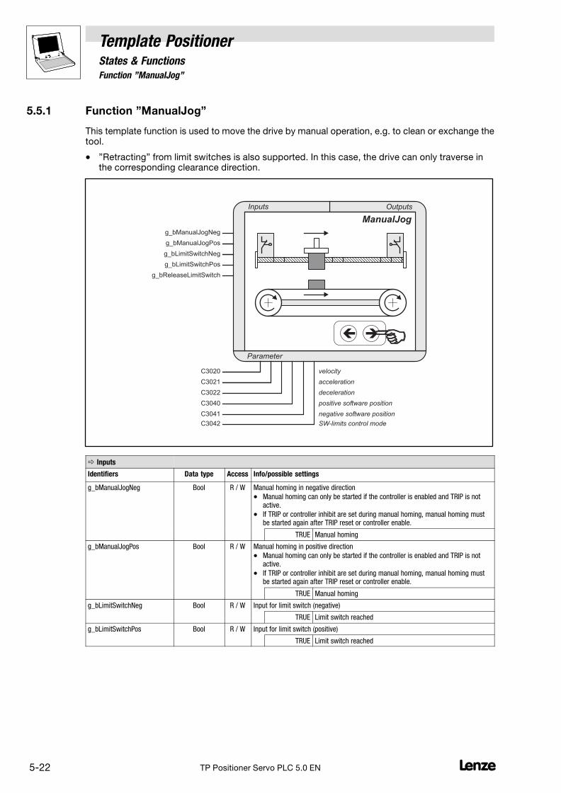
5.5.1 Function "ManualJog"
Template PositionerStates & Functions
5−22 LTP Positioner Servo PLC 5.0 EN
5.5.1 Function "ManualJog"
This template function is used to move the drive by manual operation, e.g. to clean or exchange thetool.
� "Retracting" from limit switches is also supported. In this case, the drive can only traverse inthe corresponding clearance direction.
Parameter
Inputs Outputs
g_bManualJogNeg
g_bManualJogPos
ManualJog
g_bLimitSwitchNeg
g_bLimitSwitchPos
C3021
C3020
�
velocity
acceleration
g_bReleaseLimitSwitch
C3040
C3041
C3042
positive software position
negative software position
SW-limits control mode
decelerationC3022
� Inputs
Identifiers Data type Access Info/possible settings
g_bManualJogNeg Bool R / W Manual homing in negative direction
� Manual homing can only be started if the controller is enabled and TRIP is notactive.
� If TRIP or controller inhibit are set during manual homing, manual homing mustbe started again after TRIP reset or controller enable.
TRUE Manual homing
g_bManualJogPos Bool R / W Manual homing in positive direction
� Manual homing can only be started if the controller is enabled and TRIP is notactive.
� If TRIP or controller inhibit are set during manual homing, manual homing mustbe started again after TRIP reset or controller enable.
TRUE Manual homing
g_bLimitSwitchNeg Bool R / W Input for limit switch (negative)
TRUE Limit switch reached
g_bLimitSwitchPos Bool R / W Input for limit switch (positive)
TRUE Limit switch reached

Template PositionerStates & Functions
5.5.1 Function "ManualJog"
5−23L TP Positioner Servo PLC 5.0 EN
� Inputs
Identifiers Info/possible settingsAccessData type
g_bReleaseLimitSwitch Bool R / W Sub−function "Retracting"
TRUE Retracting from the activated limit switch in the correspondingclearance direction until the limit switch is released (no longeractivated):
� g_bLimitSwitchPos = TRUE:Retracting in direction g_bLimitSwitchNeguntil g_bLimitSwitchPos = FALSE
� g_bLimitSwitchNeg = TRUE:Retracting in direction g_bLimitSwitchPosuntil g_bLimitSwitchNeg = FALSE
Parameters
Code Data type Access Info
Sub−code Possible settings Pre−setting
C3020 R / W Manual homing speed
0.0001 {0.0001 unit/s} 214000.0000 360 unit/s
C3021 R / W Acceleration
0.0001 {0.0001 unit/s2} 214000.0000 720 unit/s2
C3022 R / W Deceleration
0.0001 {0.0001 unit/s2} 214000.0000 720 unit/s2
C3040 R / W Positive software limit position
� Checking of the software limit positions: � 5−83
0.0000 {0.0001 unit} 214000.0000
0 = Software limit position deactivated
0 unit
C3041 R / W Negative software limit position
� Checking of the software limit positions: � 5−83
0.0000 {0.0001 unit} 214000.0000
0 = Software limit position deactivated
0 unit
C3042 R / W Mode of software limit position monitoring � 5−83
0 Current setpoint position + selected directionof motion
0
1 Current actual position
Note: The acceptance of new settings requires a status change to "StandBy"!
Tip!
The [unit] is to be entered in fixed−comma format with 4 decimal positions, i.e. 1 [unit] 10000.
Stop!
If the home position is not known or the software limit positions are not set, the drive can reach itsmechanical limits and parts of the machine can be damaged or destroyed during manual homing!

5.5.1 Function "ManualJog"
Template PositionerStates & Functions
5−24 LTP Positioner Servo PLC 5.0 EN
Soft start and quick stop of the drive
For a soft start and quick stop of the drive, the acceleration and deceleration for manual homing canbe separately selected under C3021/C3022.
v [m/s]
t [s]
�
t [s]
g_bManualJogPos
TRUE
FALSE
C3021 C3022
� �
Fig. 5−8 Example: Different settings for acceleration and deceleration� Soft start through slow acceleration (C3021)� Quick stop through quick deceleration (C3022)
� A quick deceleration (C3022) reduces the time between releasing the jog button and thestandstill of the drive. This makes positioning "by the eye" easier and ensures that the desiredstop position is not passed.

Template PositionerStates & Functions
5.5.1 Function "ManualJog"
5−25L TP Positioner Servo PLC 5.0 EN
Manual homing to software limit positions
If the home position is known and the software limit positions are set, the drive will start a manualhoming process to the corresponding software limit position, if manual homing has not been stoppedby resetting g_bManualJogNeg or g_bManualJogPos:
0-Position100 200 300 400 500 600-100
� �
v [m/s]
t [s]
�
t [s]
g_bManualJogPos
TRUE
FALSE
Fig. 5−9 Example: Manual homing to a positive software limit position� Negative software limit position (C3041)� Positive software limit position (C3040)
� The drive decelerates to stop at the software limit position along the selected decelerationramp (C3022) and the message "Warning NegPositionLimit" or "Warning PosPositionLimit" isindicated.
� This ensures that the set software limit positions cannot be passed in "ManualJog".

5.5.1 Function "ManualJog"
Template PositionerStates & Functions
5−26 LTP Positioner Servo PLC 5.0 EN
Manual homing to hardware limit positions (limit switches)
If the drive reaches a limit switch while homing manually, it brakes along the selected quick stop rampto standstill and the message "Fail_QSPNegLimitSwitch" or "Fail_QSPPosLimitSwitch" is indicated.The drive changes to "Trouble".
� The quick stop ramp can be set under the corresponding motor control parameters (e.g.C0105).
Retracting from limit switches
By setting g_bReleaseLimitSwitch to TRUE you can retract from an activated limit switch.
The drive then traverses in the corresponding clearance direction until the limit switch is deactivatedagain.
� with g_bLimitSwitchPos = FALSE:Retracting in direction g_bLimitSwitchNeg until g_bLimitSwitchPos = TRUE.
� with g_bLimitSwitchNeg = FALSE:Retracting in direction g_bLimitSwitchPos until g_bLimitSwitchNeg = TRUE.
Note!
Retracting from a limit switch is only possible if the limit switch is still activated.
When approaching a limit switch it therefore has to be ensured that the tripping mechanism of thelimit switch is not "passed", e.g. through an excessive mass or drive to make sure that the limit switchis activated.
The other limit switch must not be activated and error messages 400 and 401 indicated when a limitswitch is passed must have been reset.

Template PositionerStates & Functions
5.6 Status "Positioning"
5−27L TP Positioner Servo PLC 5.0 EN
5.6 Status "Positioning"
The following functions can be used for positioning:
Function Info
StandardPositioning Standard positioning � 5−35
t [s]
v [m/s]
TouchProbePositioning Remaining path positioning � 5−44
t [s]Touch probe
v [m/s]
OverchangePositioning Positioning with transition from one profile to another � 5−53
v [m/s]
t [s]
OverridePositioning Positioning with a change of profile parameters during positioning � 5−61
v [m/s]
t [s]
ChangeProfileInterface Change of profile parameters � 5−71
PositionCorrection Feed correction � 5−73

5.6 Status "Positioning"
Template PositionerStates & Functions
5−28 LTP Positioner Servo PLC 5.0 EN
Condition (transition) for a status change to "Positioning"
g_bGlobalError= FALSE (no error) �&
EnterPositioning
g_bUserQuickstop = FALSE (no user QSP) �
g_DCTRL_bImp_b = FALSE (no pulse inhibit) �
g_bPositioningEnable = TRUE �
� A status change to "Positioning" is only possible in "StandBy"!
Condition (transition) for changing back to "StandBy"
g_bGlobalError = TRUE (error occurred) ��1
ExitPositioning
g_bUserQuickstop = TRUE (user QSP) �
g_DCTRL_bImp_b = TRUE (pulse inhibit) �
g_bPositioningEnable = FALSE �&
Speed setpoint = 0 �
5.6.1 General information
In the following sub−sections you can find information and notes concerning all positioning functions:
� Assignment of profile names � Profile parameters (sub−codes) (� 5−29)
� Selection of the number of positioning profiles (� 5−29)
� Change of profile names (� 5−30)
� Entry of profile parameters (� 5−30)
� Checking whether the home position is known (� 5−30)
� Positioning modes (general) (� 5−31)
� Positioning start (� 5−32)
� Cancellation of positioning (� 5−32)
� Definition of the message window "Target position reached" (� 5−33)
� Definition of the dwell time (� 5−34)
� Jerk reduction (� 5−34)

Template PositionerStates & Functions
5.6 Status "Positioning"
5−29L TP Positioner Servo PLC 5.0 EN
5.6.1.1 Assignment of profile names � Profile parameters (sub−codes)
The profile names are assigned to the profile parameters in the data type ProfileNames (ObjectOrganizer � register Data types � folder UserDataTypes).
� The profile names can be freely selected. They have been preassigned with "Profile1","Profile2", "Profile3", etc.
� A number is assigned to every profile name. This number corresponds to the sub−codenumber of the corresponding profile parameter:
<Profile name>:=<Sub−code> Profile parameter Code/sub−code
Profile1:=1, �
Position C3100/1
Speed C3200/1
Acceleration C3300/1
Deceleration C3400/1
Final speed C3500/1
Jerk time C3600/1
Profile2:=2, �
Position C3100/2
Speed C3200/2
Acceleration C3300/2
Deceleration C3400/2
Final speed C3500/2
Jerk time C3600/2
... �
Position C3100/...
Speed C3200/...
Acceleration C3300/...
Deceleration C3400/...
Final speed C3500/...
Jerk time C3600/...
Profile n:=n, �
Position C3100/n
Speed C3200/n
Acceleration C3300/n
Deceleration C3400/n
Final speed C3500/n
Jerk time C3600/n
5.6.1.2 Selection of the number of positioning profiles
The number of available sub−codes and thus the number of profiles to be written is defined under theconstant C_wNumberOfMotionObjects. You can create max. 128 profiles. (Object Organizer/registerResources � folder Global variables � folder TemplateInterface � variable listVarTemplateSettings (CONSTANT))
� In the template, the constant has been preset to "5", i.e. the sub−codes for five profiles arealready available.
� If you change the number, the corresponding sub−codes will be available after the compilation.

5.6 Status "Positioning"
Template PositionerStates & Functions
5−30 LTP Positioner Servo PLC 5.0 EN
5.6.1.3 Change of profile names
Please observe the following instructions when changing the preselected profile names:
� Any name can be selected as profile name as long as it has not been used earlier.
� The list can be extended or shortened. (Every entry needs 2 bytes RAM.)
� The last entry must not be closed by a comma.
� If you change the selected profile names and use the sequencer of the POU UserInterface(PRG) the profile names in the input actions must also be adapted.
� We recommend to always include the profile number which corresponds to the sub−codenumber of the profile parameter codes in the name.
Example:
TYPE ProfileNames :(...Motion1:=1,Motion2:=2,...
);END TYPE
5.6.1.4 Entry of profile parameters
Profile parameters can be entered into the corresponding sub−codes using the Parameter monitor:
1. Ensure that you are logged in.
2. Use the Parameter monitor (Object Organizer� register Resources) and select the folderIndividual IEC1131 codes�POUPositioning.
3. Enter the corresponding values into the code.
Caution!
A repeated program download overwrites the code settings with the initialisation values!
To avoid this, enter the desired code initialisation values into the object Code initialization valuesof the register Resources in the Object Organizer.
5.6.1.5 Checking whether the home position is known
If the home position is not known (g_bHomePositionAvailable = FALSE), quick stop and "Trouble" willbe set when positioning modes 0, 3, 10, 13, 14 and 15 are selected.

Template PositionerStates & Functions
5.6 Status "Positioning"
5−31L TP Positioner Servo PLC 5.0 EN
5.6.1.6 Positioning modes (general)
Mode "Absolute"
In this positioning mode, the absolute target position is approached with the set profile parameters.
� Precondition: The home position must be known (g_bHomePositionAvailable = TRUE).
� The maximum distance comprises 2140000000 increments.
� It is possible to change between absolute and relative positioning without loosing the homeposition.
Mode "Modulo"
In this positioning mode, continuous relative movements (e.g. rotary table applications) are possible,since the internal path integrators are always reset before positioning starts.
� After positioning in this mode, absolute or relative positioning is no longer possible since thehome position is lost when the path integrators are reset.
� The maximum distance comprises 2140000000 increments.
Mode "Speed"
In this positioning mode, the drive traverses constantly ("constant approach"), i.e. accelerates ordecelerates to the speed defined in the profile parameters and then constantly traverses at thisspeed.
� After positioning in this mode, absolute or relative positioning is no longer possible because thepath integrators are not reset.
� The maximum distance comprises 2140000000 increments.
Mode "Relative"
In this positioning mode, the distance between current position and target position is traversed withthe set profile parameters.
� Precondition: The home position must be known (g_bHomePositionAvailable = TRUE).
� The maximum distance comprises 2140000000 increments.
� It is possible to change between relative and absolute positioning without loosing the homeposition.
Touch probe positioning modes
With touch probe positioning, a defined movement with an absolute or relative target (touch probedistance) is activated by a hardware interrupt signal.
� The actual position, which serves as reference position for the touch probe distance, is savedas soon as the hardware interrupt signal is released.
� This type of positioning is also known as remaining path positioning because a touch probesignal is often used to position a remaining path while the drive moves constantly.
� Touch probe positioning can be carried out in different modes.See function TouchProbePositioning. (� 5−44)

5.6 Status "Positioning"
Template PositionerStates & Functions
5−32 LTP Positioner Servo PLC 5.0 EN
5.6.1.7 Positioning start
Positioning is started by transferring the name of the profile to be traversed to the variableg_wMotionProfileNumber.
� For this, the template must be in the status "Positioning".
� If profile and target position are valid and the following error limit has not been exceeded, thepositioning process will be executed according to the profile parameters.
� During positioning, g_wMotionProfileNumber is "active", when the target position is reached itchanges to "Done".
� The variable g_wCurrentProfileName includes the symbolic name of the active profile, thevariable g_wCurrentProfileNumber includes the corresponding profile number.
Tip!
If you transfer a new profile name during a positioning process (g_wMotionProfileNumber = "active")to g_wMotionProfileNumber the processing of the current profile will be interrupted and the newprofile will be used.
� The new profile parameters are directly accepted, i.e. the drive does not decelerate to theselected final speed of the previous profile or brake to standstill.
5.6.1.8 Cancellation of positioning
A positioning process can be interrupted by resetting g_wPositioningEnable to FALSE. The drive willbrake to standstill along the deceleration ramp of the current profile and change into the status"StandBy".
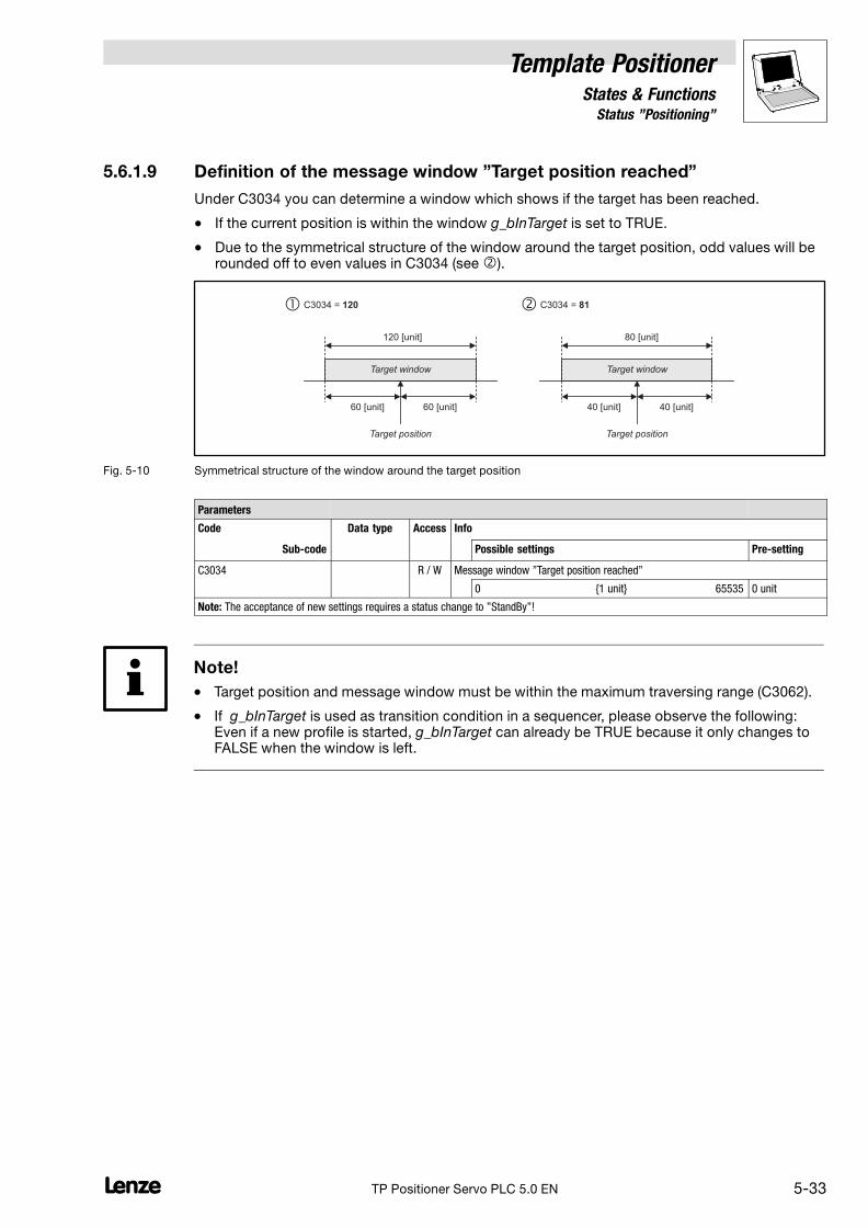
Template PositionerStates & Functions
5.6 Status "Positioning"
5−33L TP Positioner Servo PLC 5.0 EN
5.6.1.9 Definition of the message window "Target position reached"
Under C3034 you can determine a window which shows if the target has been reached.
� If the current position is within the window g_bInTarget is set to TRUE.
� Due to the symmetrical structure of the window around the target position, odd values will berounded off to even values in C3034 (see �).
Target position
120C3034 =
120 [unit]
60 [unit] 60 [unit]
Target position
C3034 = 81
80 [unit]
40 [unit] 40 [unit]
� �
Target windowTarget window
Fig. 5−10 Symmetrical structure of the window around the target position
Parameters
Code Data type Access Info
Sub−code Possible settings Pre−setting
C3034 R / W Message window "Target position reached"
0 {1 unit} 65535 0 unit
Note: The acceptance of new settings requires a status change to "StandBy"!
Note!
� Target position and message window must be within the maximum traversing range (C3062).
� If g_bInTarget is used as transition condition in a sequencer, please observe the following:Even if a new profile is started, g_bInTarget can already be TRUE because it only changes toFALSE when the window is left.

5.6 Status "Positioning"
Template PositionerStates & Functions
5−34 LTP Positioner Servo PLC 5.0 EN
5.6.1.10 Definition of the dwell time
Under C3035 you can select a dwell time to be passed after the setpoint generation for the targetposition, before a new positioning process is started.
Mechanical transient reactions can thus be considered when the tool reaches the target position.
� The dwell time starts when the setpoint has reached the target position(output g_bProfileDone = TRUE).
� After expiry of the dwell time, g_bDwellTime is set to TRUE. The output is automatically resetto FALSE when a new positioning process is started.
t [s]
v [m/s]
t [s]
g_bDone
TRUE
FALSE
t [s]
g_bDwellTime
TRUE
FALSE
Dwell time�
�
Fig. 5−11 Definition of the dwell time� Actual value profile� Setpoint profile
Parameters
Code Data type Access Info
Sub−code Possible settings Pre−setting
C3035 R / W Dwell time
0 {1 ms} 65535 50 ms
Note: The acceptance of new settings requires a status change to "StandBy"!
5.6.1.11 Jerk reduction
S−ramps (S−profiles) are used for soft acceleration and deceleration to reduce the jerk and protectthe drive components. (� 2−3)
� The selected acceleration/deceleration values will only be reached after the "jerk time" setunder C3600/x.
� Select the maximum jerk time under C1256.
� Under code C3037, you can choose between run−time−optimised S−profile generation (defaultsetting) and S−profile−optimised profile generation (the latter requires a much longerprocessing time; change the task configuration and select longer task interval times, ifnecessary).

Template PositionerStates & Functions
5.6.2 Function "StandardPositioning"
5−35L TP Positioner Servo PLC 5.0 EN
5.6.2 Function "StandardPositioning"
With this template function the drive can approach defined positions in different positioning modesby selecting linear movement profiles.
Parameter
Inputs Outputs
g_bPositioningEnable
g_byPositioningMode
g_nPosProfilerState
g_nSetVelocity_v
g_dnSetPosInternal_p
StandardPositioning
Target tool position
v
t
g_bHoldBackProfiles
C3034
dwell time
S-Profile mode
g_dnActualPositionReal
g_dnActualTargetPositionReal
g_bDwellTime
g_bProfileDone
g_bProfileBusy
g_dnActualVelocityReal
g_bInTarget
C3035
C3037
target window
Profiles:
C3100/1...n
C3200/1...n
position
velocity
C3300/1...n
C3400/1...n
C3500/1...n
acceleration
deceleration
jerk timeC3600/1...n
final velocity
g_wCurrentProfileName
g_wCurrentProfileNumber
g_dnPositionDifference_p
g_dnActualTargetPosition_p
g_dnActualPositionInternal_pg_wMotionProfileNumber
� Inputs
Identifiers Data type Access Info/possible settings
g_bPositioningEnable Bool R / W Enabling positioning
TRUE Change to "Positioning"
FALSE Cancellation of positioning, change to "StandBy"
g_byPositioningMode Byte R / W Positioning mode selection
0 Absolute positioning
� Precondition: g_bHomingDone = TRUEand g_bHomePositionAvailable = TRUE
1 Modulo positioning
� Path integrators are reset before the start.
� Application: Rotary tables
� Precondition: g_bHomingDone = TRUE
2 Constant traversing
3 Relative positioning
� max. 2147483647 increments (231 − 1)
� Path integrators are not reset before the start.
� Precondition: g_bHomingDone = TRUEand g_bHomePositionAvailable = TRUE

5.6.2 Function "StandardPositioning"
Template PositionerStates & Functions
5−36 LTP Positioner Servo PLC 5.0 EN
� Inputs
Identifiers Info/possible settingsAccessData type
g_bHoldBackProfiles Bool R / W Completing profile processing after interruption.
� If profile processing has been interrupted because of a status change from"Positioning" to another status, you can use this input to select that profileprocessing will be completed when the drive changes to "Positioning" again.
TRUE Profile processing is completed automatically afterinterruption.
FALSE Profile processing is not automatically completed afterinterruption.
When the drive changes to "Positioning" again, the interruptedpositioning process is considered to be completed(g_wMotionProfileNumber = Done).
� Inputs/outputs �
Identifiers Data type Access Info/possible settings
g_wMotionProfileNumber ProfileNames R / W Profile name
� If g_wMotionProfileNumber is used with a valid profile name, the positioningprocess starts with the profile parameters of the selected profile.
� Precondition: g_bPositioningEnable = TRUE
Display"Active"
Processing of the selected profile is not completed yet.
Display"Done"
The selected profile has been processed, the drive hasreached the target position.
Outputs �
Identifiers Data type Access Value/meaning
g_nPosProfilerState Word R Positioning status
Messages:
0 No action
1 Positioning completed
10 Acceleration phase is active
11 Constant speed phase is active
12 Deceleration phase is active
13 Reversing phase is active
100 Reset is active
101 Start values are loaded
102 Positioning stopped
103 External setpoint interface activated
200 Touch probe positioning (remaining path positioning)completed, but no touch probe signal detected.
300 Overflow of the internal path integrator
Errors:
−200 Invalid profile: Parameter acceleration = 0
−201 Invalid profile: Parameter deceleration = 0
−202 Invalid profile: Parameter speed = 0
−210 Invalid remaining path profile: Parameter acceleration = 0
−211 Invalid remaining path profile: Parameter deceleration = 0
−212 Invalid remaining path profile: Parameter speed = 0
−300 Positioning with the selected profile parameters is notplausible.
g_nSetVelocity_v Integer R Speed setpoint in [inc/ms]
� 16384 [inc] 15000 rpm
� Only to be used for encoder systems on the motor side! If a load−side encoder system is used (gearbox factor unequal 1), speed setpoint0 will be output.

Template PositionerStates & Functions
5.6.2 Function "StandardPositioning"
5−37L TP Positioner Servo PLC 5.0 EN
Outputs �
Identifiers Value/meaningAccessData type
g_dnPositionDifference_p Double integer R Position difference between setpoint and actual value in [inc]
� 65536 [inc] 1 revolution on the motor end
g_dnSetPosInternal_p Double integer R Internal setpoint angle position in [inc]
With Modulo positioning reset every time a profile is started.
g_dnActualPositionReal Double integer R Actual angle position in [unit]
� Output in fixed−comma format with 4 decimal positions: 1 [unit] 10000
g_dnActualPositionInternal_p Double integer R Actual angle position in [inc]
� 65536 [inc] 1 revolution on the motor end
� The actual integrator can overflow.
g_dnActualTargetPositionReal Double integer R Target position of the current profile in [unit]
� Output in fixed−comma format with 4 decimal positions: 1 [unit] 10000
g_dnActualTargetPosition_p Double integer R Target position of the current profile in [inc]
� 65536 [inc] 1 revolution on the motor end
g_dnActualVelocityReal Double integer R Current speed in [unit]/s
� Output in fixed−comma format with 4 decimal positions: 1 [unit/s] 10000
g_wCurrentProfileName ProfileNames R Profile name of the active profile
� When the "Positioning" status is left, g_wCurrentProfileName is set to "Done".
g_wCurrentProfileNumber Word R Profile number of the active profile
g_bInTarget Bool R Message "Target position reached"
� Window definition (C3034): � 5−33
TRUE The target position is within the window defined under C3034.
g_bDwellTime Bool R Message "Dwell time over"
� Reset to FALSE when positioning is started.
� Definition of the dwell time (C3035): � 5−34
TRUE The dwell time set under C3035 has expired.
g_bProfileBusy Bool R Message "Positioning is active"
TRUE Positioning is active.
TRUE(pulse)
g_bProfileBusy and g_bProfileDone are set to TRUE for a shorttime if target and start position are identical at the start ofabsolute positioning and positioning has therefore not beenstarted.
g_bProfileDone Bool R Message "Positioning has been completed"
TRUE Positioning has been completed.
TRUE(pulse)
g_bProfileDone and g_bProfileBusy are set to TRUE for a shorttime if target and start position are identical at the start ofabsolute positioning and positioning has therefore not beenstarted.
Parameters
Code Data type Access Info
Sub−code Possible settings Pre−setting
C3034 R / W Message window "Target position reached"
� Window definition: � 5−33
0 {1 unit} 65535 0 unit
C3035 R / W Dwell time
� Definition of the dwell time: � 5−34
0 {1 ms} 65535 50 ms
C3037 R / W Mode S−profile generation
0 Run−time−optimised 0
1 S−profile−optimised
� Requires a much longer processing time
� Further information � 7−1

5.6.2 Function "StandardPositioning"
Template PositionerStates & Functions
5−38 LTP Positioner Servo PLC 5.0 EN
Profile parameters
Code Data type Access Info
Sub−code Possible settings Pre−setting
C3100 R / W Parameter "Position" for positioning profile 1 ... n
1 ... n −214000.0000 {0.0001 unit} 214000.0000
C3200 R / W Parameter "Speed" for positioning profile 1 ... n
1 ... n 0.0001 {0.0001 unit/s} 214000.0000
C3300 R / W Parameter "Acceleration" for positioning profile 1 ... n
1 ... n 0.0001 {0.0001 unit/s2} 214000.0000
C3400 R / W Parameter "Deceleration" for positioning profile 1 ... n
1 ... n 0.0001 {0.0001 unit/s2} 214000.0000
C3500 R / W Parameter "Dwell time" for positioning profile 1 ... n
1 ... n 0.0000 {0.0001 unit/s} 214000.0000
C3600 R / W Parameter "Jerk time" for positioning profile 1 ... n
1 ... n 0.000 {0.001 s} 10.000
Standard profile generator modes−1−
The profile generator uses the following standard positioning modes:
Mode Info
0 Absolute positioning This mode is based on absolute zero. In general, zero is found by homing and transferredto the actual position integrator of the profile generator. All profiles refer to this zero.
1 Relative positioning This mode does not select an absolute position but uses distances.
� The internal path integrators are set to "0" before every positioning process. It is notpossible to run an absolute positioning process after a relative positioning process.
Example:
If a relative positioning process in mode 1 is activated after an absolute positioning processin mode 0, the zero position could not be found after the system had switched back tomode 0. The axis then uses the last start position of mode 1 as a reference.
2 Constant traversing This mode does not approach a defined position, but follows the profile.
� Acceleration and deceleration are based on profile values.
� The traversing direction is defined by the sign of the traversing speed.
3 Relative positioning (max. 230) Like mode 1, "Relative positioning", only the internal path integrators are not reset, butcontinue to be incremented.
� The path integrators are limited to 230.
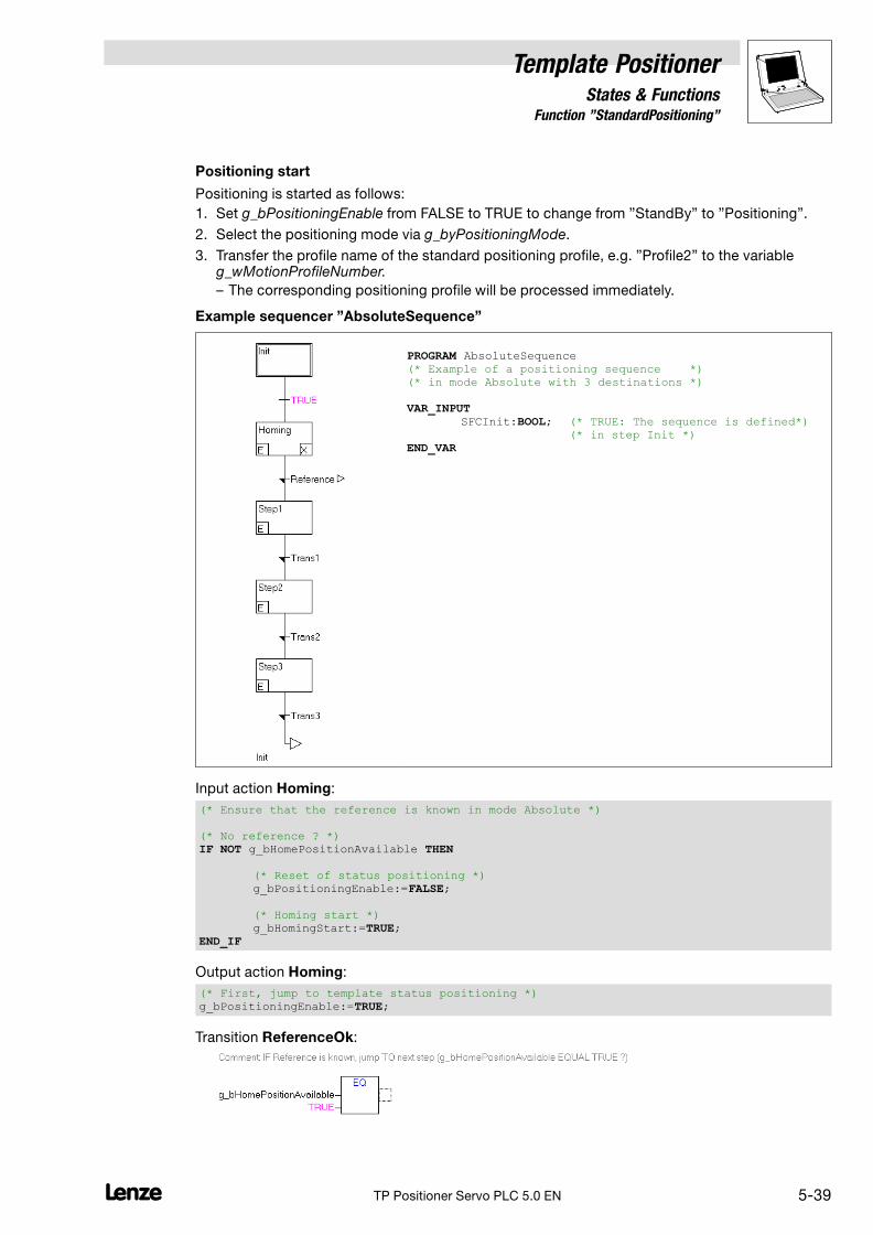
Template PositionerStates & Functions
5.6.2 Function "StandardPositioning"
5−39L TP Positioner Servo PLC 5.0 EN
Positioning start
Positioning is started as follows:
1. Set g_bPositioningEnable from FALSE to TRUE to change from "StandBy" to "Positioning".
2. Select the positioning mode via g_byPositioningMode.
3. Transfer the profile name of the standard positioning profile, e.g. "Profile2" to the variableg_wMotionProfileNumber.
– The corresponding positioning profile will be processed immediately.
Example sequencer "AbsoluteSequence"
PROGRAM AbsoluteSequence(* Example of a positioning sequence *)(* in mode Absolute with 3 destinations *)
VAR_INPUTSFCInit:BOOL; (* TRUE: The sequence is defined*)
(* in step Init *)END_VAR
Input action Homing:
(* Ensure that the reference is known in mode Absolute *)
(* No reference ? *)IF NOT g_bHomePositionAvailable THEN
(* Reset of status positioning *)g_bPositioningEnable:=FALSE;
(* Homing start *)g_bHomingStart:=TRUE;
END_IF
Output action Homing:
(* First, jump to template status positioning *)g_bPositioningEnable:=TRUE;
Transition ReferenceOk:
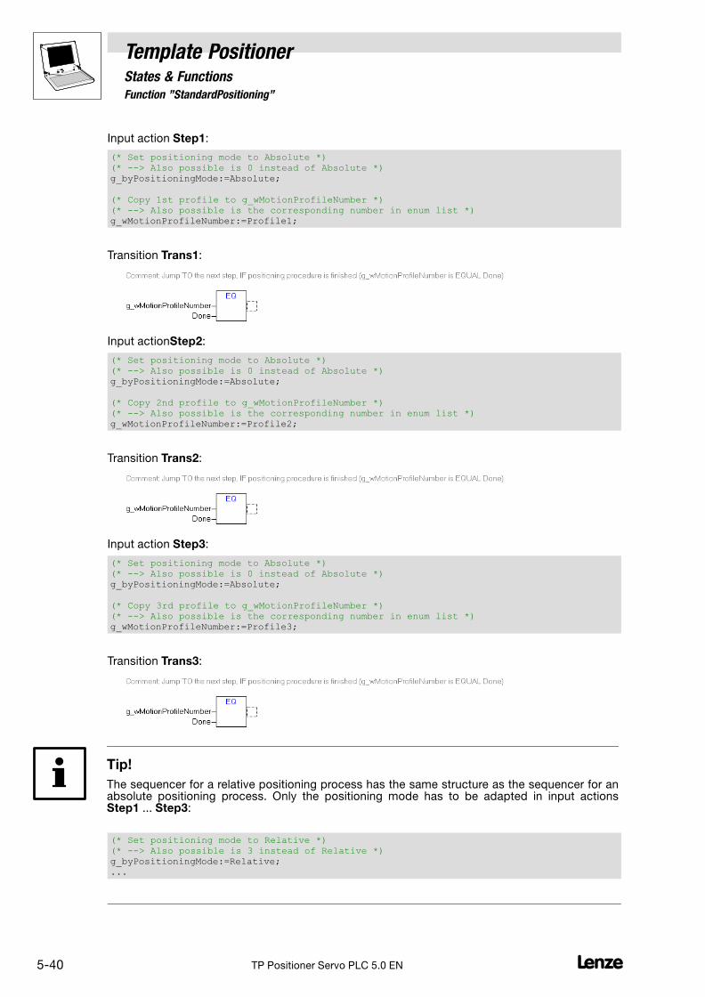
5.6.2 Function "StandardPositioning"
Template PositionerStates & Functions
5−40 LTP Positioner Servo PLC 5.0 EN
Input action Step1:
(* Set positioning mode to Absolute *)(* −−> Also possible is 0 instead of Absolute *)g_byPositioningMode:=Absolute;
(* Copy 1st profile to g_wMotionProfileNumber *)(* −−> Also possible is the corresponding number in enum list *)g_wMotionProfileNumber:=Profile1;
Transition Trans1:
Input actionStep2:
(* Set positioning mode to Absolute *)(* −−> Also possible is 0 instead of Absolute *)g_byPositioningMode:=Absolute;
(* Copy 2nd profile to g_wMotionProfileNumber *)(* −−> Also possible is the corresponding number in enum list *)g_wMotionProfileNumber:=Profile2;
Transition Trans2:
Input action Step3:
(* Set positioning mode to Absolute *)(* −−> Also possible is 0 instead of Absolute *)g_byPositioningMode:=Absolute;
(* Copy 3rd profile to g_wMotionProfileNumber *)(* −−> Also possible is the corresponding number in enum list *)g_wMotionProfileNumber:=Profile3;
Transition Trans3:
Tip!
The sequencer for a relative positioning process has the same structure as the sequencer for anabsolute positioning process. Only the positioning mode has to be adapted in input actionsStep1 ... Step3:
(* Set positioning mode to Relative *)(* −−> Also possible is 3 instead of Relative *)g_byPositioningMode:=Relative;...

Template PositionerStates & Functions
5.6.2 Function "StandardPositioning"
5−41L TP Positioner Servo PLC 5.0 EN
Example sequencer "SpeedSequence"
PROGRAM SpeedSequence(* Example of a positioning sequence in mode Speed *)(* with 3 destinations *)
VAR_INPUTSFCInit : BOOL;(* TRUE: The sequence is defined in step Init *)
END_VAR
VARSpeedTimer : TON;(* Timer for starting different speed profiles *)(* without destinations *)
END_VAR
Output action Init:
(* First, jump to template status positioning *)g_bPositioningEnable:=TRUE;
Input action Step1:
(* Set positioning mode to Speed *)(* −−> Also possible is 2 instead of Speed *)g_byPositioningMode:=Speed;
(* Copy 1st profile to g_wMotionProfileNumber *)(* −−> Also possible is the corresponding number in enum list *)g_wMotionProfileNumber:=Profile19;
(* Initialisation of timer to generate transition for the next step, *)(* because no Done status is transferred to g_wMotionControlNumber *)SpeedTimer(IN:=TRUE, PT:=t#400ms);
Output action Step1:
(* Reset SpeedTimer to start new timer process in next step *)SpeedTimer(IN:=FALSE);
Transition Trans1:

5.6.2 Function "StandardPositioning"
Template PositionerStates & Functions
5−42 LTP Positioner Servo PLC 5.0 EN
Input actionStep2:
(* Set positioning mode to Speed *)(* −−> Also possible is 2 instead of Speed *)g_byPositioningMode:=Speed;
(* Copy 2nd profile to g_wMotionProfileNumber *)(* −−> Also possible is the corresponding number in enum list *)g_wMotionProfileNumber:=Profile20;
(* Initialisation of timer to generate transition for the next step, *)(* because no Done status is transferred to g_wMotionControlNumber *)SpeedTimer(IN:=TRUE, PT:=t#600ms);
Output action Step2:
(* Reset SpeedTimer to start new timer process in next step *)SpeedTimer(IN:=FALSE);
Transition Trans2:
Input action Step3:
(* Set positioning mode to Speed *)(* −−> Also possible is 2 instead of Speed *)g_byPositioningMode:=Speed;
(* Copy 3rd profile to g_wMotionProfileNumber *)(* −−> Also possible is the corresponding number in enum list *)g_wMotionProfileNumber:=Profile21;
(* Initialisation of timer to generate transition for the next step, *)(* because no Done status is transferred to g_wMotionControlNumber *)SpeedTimer(IN:=TRUE, PT:=t#800ms);
Output action Step3:
(* Reset SpeedTimer to start new timer process in next step *)SpeedTimer(IN:=FALSE);
Transition Trans3:

Template PositionerStates & Functions
5.6.2 Function "StandardPositioning"
5−43L TP Positioner Servo PLC 5.0 EN
Function "MoveAxis" for easy positioning
The function MoveAxis is a command interface of the Template Positioner which enables easypositioning.
� The parameter "Final speed" is not implemented in this function.
� Calling this function changes the profile parameters of profile no. 1!
� The positioning mode (g_byPositioningMode) must be selected before the function isactivated.
Example: Activating the function MoveAxis for absolute positioning:
g_byPositioningMode:=Absolute; (* see positioning modes *)
MoveAxis( dnPosition:=6000000, (* Profile parameter position [units x 10000] *) dnVelocity:=1000000, (* Profile parameter velocity [units/s x 10000] *) dnAcceleration:=10000000, (* Profile parameter acceleration [units/s^2 x 10000] *) dnDeceleration:=10000000, (* Profile parameter deceleration [units/s^2 x 10000] *) dnJerkTime:=0 (* Profile parameter jerk time [s x 1000] *) );

5.6.3 Function "TouchProbePositioning"
Template PositionerStates & Functions
5−44 LTP Positioner Servo PLC 5.0 EN
5.6.3 Function "TouchProbePositioning"
With this template function the drive can approach defined positions in different positioning modesby selecting linear movement profiles.
If touch probe is identified during the traversing process the drive automatically changes from theprofile g_MotionProfileNumber to the profile g_AuxMotionProfileNumber. The profile generator thencontinues the positioning process with the new parameters in the corresponding positioning mode(remaining path positioning).
g_dnActualPositionReal
g_dnActualPositionInternal_p
g_bDwellTime
g_bProfileDone
g_bProfileBusy
g_dnActualVelocityReal
g_bInTarget
g_bAuxProfileBusy
g_wCurrentProfileName
g_wCurrentProfileNumber
g_dnActualTargetPositionReal
g_dnActualTargetPosition_p
g_nPosProfilerState
g_nSetVelocity_v
g_dnSetPosInternal_p
g_dnPositionDifference_p
C3034
dwell time
bounce time
S-Profile mode
C3035
C3036
C3037
target window
Profiles:
C3100/1...n
C3200/1...n
position
velocity
C3300/1...n
C3400/1...n
C3500/1...n
acceleration
deceleration
jerk timeC3600/1...n
final velocity
g_bPositioningEnable
g_byPositioningMode
g_wMotionProfileNumber
g_wAuxMotionProfileNumber
g_bTPEnable
g_byEdgeTouchProbeDIGIN_3
g_dnDelayTouchProbeDIGIN_3_p
g_byEdgeTouchProbeDIGIN_4
g_dnDelayTouchProbeDIGIN_4_p
g_bUserTPEnable
g_bUserActTPReceived
g_dnUserActLastScan_p
g_bHoldBackProfiles
Parameter
Inputs Outputs
TouchProbePositioning
v [m/s]
t [s]touch probe
aux motion profile

Template PositionerStates & Functions
5.6.3 Function "TouchProbePositioning"
5−45L TP Positioner Servo PLC 5.0 EN
� Inputs
Identifiers Data type Access Info/possible settings
g_bPositioningEnable Bool R / W Enabling positioning
TRUE Change to "Positioning"
FALSE Cancellation of positioning, change to "StandBy"
g_byPositioningMode Byte R / W Selection of positioning modes with touch probe (remaining path positioning):
10 Absolute positioning with relative remaining path positioning
11 Modulo positioning with relative remaining path positioning
� Path integrators are reset before the start.
� Application: Rotary tables
12 Constant traversing with relative remaining path positioning
13 Relative positioning with relative remaining path positioning
� max. 2147483647 increments (231 − 1)
� Path integrators are not reset before the start.
14 Absolute positioning with absolute remaining path positioning
15 Relative positioning with absolute remaining path positioning
� Path integrators are not reset before the start.
g_bTPEnable Bool R / W Enabling touch probe positioning via the touch probe interface of the template
FALSE Touch probe interface is inhibited
TRUE Touch probe interface is enabled
g_byEdgeTouchProbeDIGIN_1 Byte R / W Edge sensitivity of touch probe input 1
0 Rising signal
1 Falling signal
2 Rising and falling signal
3 Touch probe detection off
g_dnDelayTouchProbeDIGIN_1_p
Double integer R / W Dead time compensation of the TP sensor at touch probe input 1
� Value in [inc] referred to the motor shaft.
g_byEdgeTouchProbeDIGIN_2 Byte R / W Edge sensitivity of touch probe input 2
0 Rising signal
1 Falling signal
2 Rising and falling signal
3 Touch probe detection off
g_dnDelayTouchProbeDIGIN_2_p
Double integer R / W Dead time compensation of the TP sensor at touch probe input 2
� Value in [inc] referred to the motor shaft.
g_byEdgeTouchProbeDIGIN_3 Byte R / W Edge sensitivity of touch probe input 3
0 Rising signal
1 Falling signal
2 Rising and falling signal
3 Touch probe detection off
g_dnDelayTouchProbeDIGIN_3_p
Double integer R / W Dead time compensation of the TP sensor at touch probe input 3
� Value in [inc] referred to the motor shaft.
g_bUserTPEnable Bool R / W Enabling touch probe positioning via the user−defined interface
FALSE User−defined interface is inhibited
TRUE User−defined interface is enabled
g_bUserActTPReceived Bool R / W User−defined interface for touch probe: Receiving touch probe signals
� Connect this input e.g. with the output variableg_MCTRL_bActTPReceived_b of the Target Interface.
TRUE Receive new touch probe signal
g_dnUserActLastScan_p Double integer R / W User−defined interface for touch probe: Current LastScan value
� Connect this input e.g. with the output variableg_MCTRL_dnActLastScan_p of the Target Interface.

5.6.3 Function "TouchProbePositioning"
Template PositionerStates & Functions
5−46 LTP Positioner Servo PLC 5.0 EN
� Inputs
Identifiers Info/possible settingsAccessData type
g_bHoldBackProfiles Bool R / W Completing profile processing after interruption.
� If profile processing has been interrupted because of a status change from"Positioning" to another status, you can use this input to select that profileprocessing will be completed when the drive changes to "Positioning" again.
TRUE Profile processing is completed automatically afterinterruption.
FALSE Profile processing is not automatically completed afterinterruption.
When the drive changes to "Positioning" again, the interruptedpositioning process is considered to be completed(g_wMotionProfileNumber = Done).
Note!
If the digital input X5/E4 is used for the touch probe signal of the function block MCTRL, the programcan only evaluate the touch probe if code C0911 = 1 (touch probe via terminal) is set. During homingwith motor encoder zero pulse evaluation, the template sets code C0911 = 0.
� Inputs/outputs �
Identifiers Data type Access Value/meaning
g_wMotionProfileNumber ProfileNames R / W Profile name
� If g_wMotionProfileNumber is used with a valid profile name, the positioningprocess starts with the profile parameters of the selected profile.
� Precondition: g_bMotionStart = TRUE
Display"Active"
Processing of the selected profile is not completed yet.
Display"Done"
The selected profile has been processed, the drive hasreached the target position.
g_wAuxMotionProfileNumber ProfileNames R / W Name of the profile used for remaining path positioning
Outputs �
Identifiers Data type Access Value/meaning
g_nPosProfilerState Word R Positioning status
Messages:
0 No action
1 Positioning completed
10 Acceleration phase is active
11 Constant speed phase is active
12 Deceleration phase is active
13 Reversing phase is active
100 Reset is active
101 Start values are loaded
102 Positioning stopped
103 External setpoint interface activated
200 Touch probe positioning (remaining path positioning)completed, but no touch probe signal detected.
300 Overflow of the internal path integrator
Errors:
−200 Invalid profile: Parameter acceleration = 0
−201 Invalid profile: Parameter deceleration = 0
−202 Invalid profile: Parameter speed = 0
−210 Invalid remaining path profile: Parameter acceleration = 0
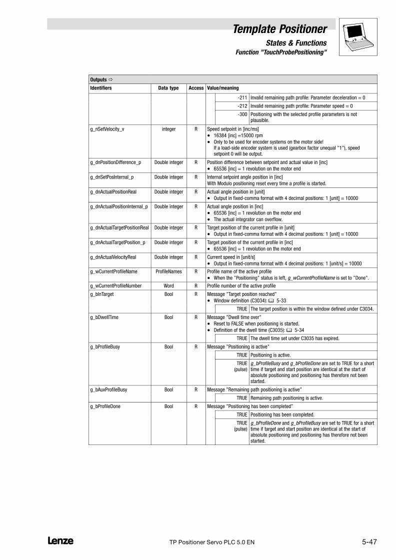
Template PositionerStates & Functions
5.6.3 Function "TouchProbePositioning"
5−47L TP Positioner Servo PLC 5.0 EN
Outputs �
Identifiers Value/meaningAccessData type
−211 Invalid remaining path profile: Parameter deceleration = 0
−212 Invalid remaining path profile: Parameter speed = 0
−300 Positioning with the selected profile parameters is notplausible.
g_nSetVelocity_v integer R Speed setpoint in [inc/ms]
� 16384 [inc] 15000 rpm
� Only to be used for encoder systems on the motor side!If a load−side encoder system is used (gearbox factor unequal "1"), speedsetpoint 0 will be output.
g_dnPositionDifference_p Double integer R Position difference between setpoint and actual value in [inc]
� 65536 [inc] 1 revolution on the motor end
g_dnSetPosInternal_p Double integer R Internal setpoint angle position in [inc]
With Modulo positioning reset every time a profile is started.
g_dnActualPositionReal Double integer R Actual angle position in [unit]
� Output in fixed−comma format with 4 decimal positions: 1 [unit] 10000
g_dnActualPositionInternal_p Double integer R Actual angle position in [inc]
� 65536 [inc] 1 revolution on the motor end
� The actual integrator can overflow.
g_dnActualTargetPositionReal Double integer R Target position of the current profile in [unit]
� Output in fixed−comma format with 4 decimal positions: 1 [unit] 10000
g_dnActualTargetPosition_p Double integer R Target position of the current profile in [inc]
� 65536 [inc] 1 revolution on the motor end
g_dnActualVelocityReal Double integer R Current speed in [unit/s]
� Output in fixed−comma format with 4 decimal positions: 1 [unit/s] 10000
g_wCurrentProfileName ProfileNames R Profile name of the active profile
� When the "Positioning" status is left, g_wCurrentProfileName is set to "Done".
g_wCurrentProfileNumber Word R Profile number of the active profile
g_bInTarget Bool R Message "Target position reached"
� Window definition (C3034): � 5−33
TRUE The target position is within the window defined under C3034.
g_bDwellTime Bool R Message "Dwell time over"
� Reset to FALSE when positioning is started.
� Definition of the dwell time (C3035): � 5−34
TRUE The dwell time set under C3035 has expired.
g_bProfileBusy Bool R Message "Positioning is active"
TRUE Positioning is active.
TRUE(pulse)
g_bProfileBusy and g_bProfileDone are set to TRUE for a shorttime if target and start position are identical at the start ofabsolute positioning and positioning has therefore not beenstarted.
g_bAuxProfileBusy Bool R Message "Remaining path positioning is active"
TRUE Remaining path positioning is active.
g_bProfileDone Bool R Message "Positioning has been completed"
TRUE Positioning has been completed.
TRUE(pulse)
g_bProfileDone and g_bProfileBusy are set to TRUE for a shorttime if target and start position are identical at the start ofabsolute positioning and positioning has therefore not beenstarted.

5.6.3 Function "TouchProbePositioning"
Template PositionerStates & Functions
5−48 LTP Positioner Servo PLC 5.0 EN
Parameters
Code Data type Access Info
Sub−code Possible settings Pre−setting
C3034 R / W Message window "Target position reached"
� Window definition: � 5−33
0 {1 unit} 65535 0 unit
C3035 R / W Dwell time
� Definition of the dwell time: � 5−34
0 {1 ms} 65535 50 ms
C3036 R / W Debounce time for touch probe input
0 {1 ms} 65535 0 ms
C3037 R / W Mode S−profile generation
0 Run−time−optimised 0
1 S−profile−optimised
� Requires a much longer processing time
� Further information � 7−1
Profile parameters
Code Data type Access Info
Sub−code Possible settings Pre−setting
C3100 R / W Parameter "Position" for positioning profile 1 ... n
1 ... n −214000.0000 {0.0001 unit} 214000.0000
C3200 R / W Parameter "Speed" for positioning profile 1 ... n
1 ... n 0.0001 {0.0001 unit/s} 214000.0000
C3300 R / W Parameter "Acceleration" for positioning profile 1 ... n
1 ... n 0.0001 {0.0001 unit/s2} 214000.0000
C3400 R / W Parameter "Deceleration" for positioning profile 1 ... n
1 ... n 0.0001 {0.0001 unit/s2} 214000.0000
C3500 R / W Parameter "Dwell time" for positioning profile 1 ... n
1 ... n 0.0000 {0.0001 unit/s} 214000.0000
C3600 R / W Parameter "Jerk time" for positioning profile 1 ... n
1 ... n 0.000 {0.001 s} 10.000

Template PositionerStates & Functions
5.6.3 Function "TouchProbePositioning"
5−49L TP Positioner Servo PLC 5.0 EN
Touch probe evaluation
You can either use the touch probe interface of the template or a user−defined interface to evaluatethe touch probe signals in the user program.
Set
� g_bTPEnable to TRUE to enable the touch probe interface of the templateor
� g_bUserTPEnable to TRUE to enable the user−defined interface.
Note!
The user−defined interface consists of the input variables g_bActTPReceived andg_dnUserLastScan_p. Use the functions & FBs of the function library LenzeTPDrv.lib to configureit.
If the user−defined interface is enabled ensure that the touch probe interface of the template isinhibited (g_bTPEnable = FALSE).
For a correct evaluation of the touch probe signals, the user program processing the touch probesignals should be added to the task configuration before "Program_Task1".
Remaining path positioning
Just like with a standard positioning process, with remaining path positioning (modes 10 ... 15) thedrive first processes the standard profile g_wMotionProfileNumber in the corresponding mode.
If touch probe is identified during traversing the drive automatically changes to the profileg_wAuxMotionProfileNumber. The profile generator then continues positioning with the newparameters in the corresponding positioning mode.
v [m/s]
t [s]
� �
Touch probe
t [s]
� �
Touch probe
v [m/s]
Fig. 5−12 Example: Remaining path positioning after touch probe identification� Standard profile (g_wMotionProfileNumber)� Additional profile for remaining path positioning (g_wAuxMotionProfileNumber)
� If remaining path positioning is active TRUE is output at g_bAuxProfileBusy.
� If touch probe is activated once again during remaining path positioning, positioning startsagain, i.e. the second remaining path positioning profile will be processed once again from thecurrent position. This is only possible if the corresponding positioning mode and the remainingpath positioning profile are still selected.
� Under C3036 you can set the debounce time for the touch probe input. After touch probeidentification, the evaluation of touch probe signals will be deactivated for the time selectedunder C3036.

5.6.3 Function "TouchProbePositioning"
Template PositionerStates & Functions
5−50 LTP Positioner Servo PLC 5.0 EN
Note!
If the standard profile has been completely processed without touch probe identification, message200 ("No touch probe identified) will be output at g_nPosProfilerState.
The software limit positions are not checked before the touch probe profile is started. If a softwarelimit position is reached during remaining path positioning user QSP is activated. Use the templatefunction ManualJog for retracting from the software limit positions. (� 5−22)
Profile generator modes for remaining path positioning−2−
The profile generator uses the following modes for remaining path positioning with touch probe:
Mode Info
10 Absolute positioningwith relative remaining path positioning
This mode is based on absolute zero. In general, zero is found by homing and transferredto the actual position integrator of the profile generator. All profiles refer to this zero.
� If touch probe is detected the profile generator automatically changes to the additionalprofile g_AuxMotionProfileNumber and executes a relative positioning process with thecorresponding profile parameters.
11 Modulo positioningwith relative remaining path positioning
This mode does not select an absolute position but uses distances.
� If touch probe is detected the profile generator automatically changes to the additionalprofile g_AuxMotionProfileNumber and executes a relative positioning process with thecorresponding profile parameters.
12 Constant traversingwith relative remaining path positioning
See mode 2, "Constant traversing". � 5−35
� If touch probe is detected the profile generator automatically changes to the additionalprofile g_AuxMotionProfileNumber and executes a relative positioning process with thecorresponding profile parameters.
13 Relative positioningwith relative remaining path positioning
Like mode 1, "Relative positioning", only the internal path integrators are not reset, butcontinue to be incremented (internally limited to 231 − 1).
� If touch probe is detected the profile generator automatically changes to the additionalprofile g_AuxMotionProfileNumber and executes a relative positioning process with thecorresponding profile parameters.
14 Absolute positioning with absolute remaining path positioning
See mode 0 "Absolute positioning".
� If touch probe is detected the profile generator automatically changes to the additionalprofile g_AuxMotionProfileNumber and executes an absolute positioning process withthe corresponding profile parameters.
15 Relative positioningwith absolute remaining path positioning
See mode 3 "Relative positioning".
� If touch probe is detected the profile generator automatically changes to the additionalprofile g_AuxMotionProfileNumber and executes an absolute positioning process withthe corresponding profile parameters.
� In this mode, the internal path integrators are not reset, but continue to be incremented(internally limited to 231 − 1).
Note!
� With positioning modes 10, 13, 14 and 15 the home position must be known.
� In positioning mode 11 the home position is reset (deleted).
– Reason for this is the reset of the path integrators in the profile generator which prevents anoverflow/incremental loss during continuous movements.
� In positioning mode 12 the home position is reset (deleted) after a possible overflow of theinternal path integrators.
– Reason: During constant traversing, the path integrators may overflow. Otherwise, the drivewould approach a wrong position if absolute positioning is started after an overflow.

Template PositionerStates & Functions
5.6.3 Function "TouchProbePositioning"
5−51L TP Positioner Servo PLC 5.0 EN
Positioning start
Positioning is started as follows:
1. Set g_bPositioningEnable from FALSE to TRUE to change from "StandBy" to "Positioning".
2. Use g_byPositioningMode to select the positioning mode (10 ... 15).
3. Transfer the profile name of the remaining path positioning profile, e.g. "Profile3" to thevariable g_wAuxMotionProfileNumber.
– The positioning profile is processed after touch probe has been identified.
4. Transfer the profile name of the standard positioning profile, e.g. "Profile2" to the variableg_wMotionProfileNumber.
– The corresponding positioning profile will be processed immediately.
Example sequencer "TouchProbeSequence"
PROGRAM TouchProbeSequence(* Example of a positioning sequence in mode Absolute *)(* with 3 destinations and TP functionality *)
VAR_INPUTSFCInit :BOOL;(* TRUE: The sequence is defined in step Init *)
END_VAR
Input action Homing:
(* Ensure that the reference is known in mode Absolute *)
(* No reference ? *)IF NOT g_bHomePositionAvailable THEN
(* Reset of status positioning *)g_bPositioningEnable:=FALSE;
(* Homing start *)g_bHomingStart:=TRUE;
END_IF
Output action Homing:
(* First, jump to template status positioning *)g_bPositioningEnable:=TRUE;

5.6.3 Function "TouchProbePositioning"
Template PositionerStates & Functions
5−52 LTP Positioner Servo PLC 5.0 EN
Transition ReferenceOk:
Input action Step1:
(* Start TouchProbe positioning process with positive edge at digital input E3 whileactual profile is in progress *)(* Set positioning mode to AbsoluteTPAbsolute −−> Also possible is 14 instead ofAbsolute *)g_byPositioningMode:=AbsoluteTPAbsolute;
(* Configuration of TouchProbe source at digital input E3 *)(* TouchProbe at positive edge *)g_byEdgeTouchProbeDIGIN_3 := 0;
(* No TouchProbe delay [incr] *)g_dnDelayTouchProbeDIGIN_3_p := 0;
(* Copy auxiliary profile to g_wAuxMotionProfileNumber, which is driven if TP−edge isdetected −−> Also possible is the corresponding number in enum list *)g_wAuxMotionProfileNumber:=Profile5;
Transition Trans4:
Input actionStep2:
(* Set TouchProbe enable bit to TRUE to enable TouchProbe positioning *)g_bTPEnable:=TRUE;
(* Copy 1st profile to g_wMotionProfileNumber −−> Also possible is the correspondingnumber in enum list *)g_wMotionProfileNumber:=Profile4;
(* Configure TouchProbe positioning as described *)(* 1 −> Add DIGIN/DIGOUT to control configuration *)(* 2 −> Select TP source and setup under Var_TouchProbe *)
Transition Trans1:
Input action Step3:
(* Deactivate TouchProbe positioning to reset enable interface variable *)g_bTPEnable:=FALSE;
(* Set positioning mode to Absolute −−> Also possible is 0 instead of Absolute *)g_byPositioningMode:=Absolute;
(* Copy 2nd profile to g_wMotionProfileNumber −−> Also possible is the correspondingnumber in enum list *)g_wMotionProfileNumber:=Profile6;
Transition Trans2:

Template PositionerStates & Functions
5.6.4 Function "OverchangePositioning"
5−53L TP Positioner Servo PLC 5.0 EN
5.6.4 Function "OverchangePositioning"
This template function is used for profile connections with "overchange", i.e. the drive traverses ata selected final speed (unequal "0") from one profile to another.
Parameter
Inputs Outputs
g_bPositioningEnable
g_byPositioningMode
OverchangePositioning
v
t
g_wMotionProfileNumber
g_dnActualPositionReal
g_dnActualPositionInternal_p
g_dnActualVelocityReal
g_bDwellTime
g_bProfileDone
g_bProfileBusy
g_bInTarget
g_wCurrentProfileName
g_wCurrentProfileNumber
g_bOverchangeEnable
g_wOverchangeProfileNumber
g_dnActualTargetPositionReal
g_dnActualTargetPosition_p
g_bHoldBackProfiles
g_nPosProfilerState
g_nSetVelocity_v
g_dnSetPosInternal_p
g_dnPositionDifference_p
C3034
dwell time
S-Profile mode
C3035
C3037
target window
Profiles:
C3100/1...n
C3200/1...n
position
velocity
C3300/1...n
C3400/1...n
C3500/1...n
acceleration
deceleration
jerk timeC3600/1...n
final velocity
� Inputs
Identifiers Data type Access Info/possible settings
g_bPositioningEnable Bool R / W Enabling positioning
TRUE Change to "Positioning"
FALSE Cancellation of positioning, change to "StandBy"
g_bOverchangeEnable Bool R / W Enabling overchange
FALSE Overchange is deactivated.
TRUE Overchange is enabled.

5.6.4 Function "OverchangePositioning"
Template PositionerStates & Functions
5−54 LTP Positioner Servo PLC 5.0 EN
� Inputs
Identifiers Info/possible settingsAccessData type
g_byPositioningMode Byte R / W Positioning mode selection
0 Absolute positioning
� Precondition: g_bHomingDone = TRUEand g_bHomePositionAvailable = TRUE
1 Relative positioning
� Path integrators are reset before the start.
� Application: Rotary tables
� Precondition: g_bHomingDone = TRUE
2 Constant traversing
3 Relative positioning
� max. 2147483647 increments (231−1)
� Path integrators are not reset before the start.
� Precondition: g_bHomingDone = TRUEand g_bHomePositionAvailable = TRUE
Selection of positioning modes with touch probe (remaining path positioning):
10 Absolute positioning with relative remaining path positioning
11 Modulo positioning with relative remaining path positioning
� Path integrators are reset before the start.
� Application: Rotary tables
12 Constant traversing with relative remaining path positioning
13 Relative positioning with relative remaining path positioning
� max. 2147483647 increments (231−1)
� Path integrators are not reset before the start.
14 Absolute positioning with absolute remaining path positioning
15 Relative positioning with absolute remaining path positioning
� Path integrators are not reset before the start.
g_bHoldBackProfiles Bool R / W Completing profile processing after interruption.
� If profile processing has been interrupted because of a status change from"Positioning" to another status, you can use this input to select that profileprocessing will be completed when the drive changes to "Positioning" again.
TRUE Profile processing is completed automatically afterinterruption.
FALSE Profile processing is not automatically completed afterinterruption.
When the drive changes to "Positioning" again, the interruptedpositioning process is considered to be completed(g_wMotionProfileNumber = Done).
� Inputs/outputs �
Identifiers Data type Access Info/possible settings
g_wMotionProfileNumber ProfileNames R / W Profile name
� If g_wMotionProfileNumber is used with a valid profile name, the positioningprocess starts with the profile parameters of the selected profile.
� Precondition: g_bPositioningEnable = TRUE
Display"Active"
Processing of the selected profile is not completed yet.
Display"Done"
The selected profile has been processed, the drive hasreached the target position.
� If several profiles are connected by means of overchange, polling in the transitionof g_wMotionProfileNumber = Done is only necessary for the last profile (seeprogramming example transition Trans3).
g_wOverchangeProfileNumber
ProfileNames R / W Name of the profile to be started automatically
Display"Active"
The profile parameters of the overchange profile are beingtransferred.
Display"Done"
The profile parameters of the selected overchange profile havebeen transferred. This variable does not indicate completion ofthe profile generation of the following profile.

Template PositionerStates & Functions
5.6.4 Function "OverchangePositioning"
5−55L TP Positioner Servo PLC 5.0 EN
Outputs �
Identifiers Data type Access Value/meaning
g_nPosProfilerState Word R Positioning status
Messages:
0 No action
1 Positioning completed
10 Acceleration phase is active
11 Constant speed phase is active
12 Deceleration phase is active
13 Reversing phase is active
100 Reset is active
101 Start values are loaded
102 Positioning stopped
103 External setpoint interface activated
200 Touch probe positioning (remaining path positioning)completed, but no touch probe signal detected.
300 Overflow of the internal path integrator
Errors:
−200 Invalid profile: Parameter acceleration = 0
−201 Invalid profile: Parameter deceleration = 0
−202 Invalid profile: Parameter speed = 0
−210 Invalid remaining path profile: Parameter acceleration = 0
−211 Invalid remaining path profile: Parameter deceleration = 0
−212 Invalid remaining path profile: Parameter speed = 0
−300 Positioning with the selected profile parameters is notplausible.
g_nSetVelocity_v Integer R Speed setpoint in [inc/ms]
� 16384 [inc] 15000 rpm
� Only to be used for encoder systems on the motor side! If a load−side encoder system is used (gearbox factor unequal 1), speed setpoint0 will be output
g_dnPositionDifference_p Double integer R Position difference between setpoint and actual value in [inc]
� 65536 [inc] 1 revolution on the motor end
g_dnSetPosInternal_p Double integer R Internal setpoint angle position in [inc]
With Modulo positioning reset every time a profile is started.
g_dnActualPositionReal Double integer R Actual angle position in [unit]
� Output in fixed−comma format with 4 decimal positions: 1 [unit] 10000
g_dnActualPositionInternal_p Double integer R Actual angle position in [inc]
� 65536 [inc] 1 revolution on the motor end
� The actual integrator can overflow.
g_dnActualTargetPositionReal Double integer R Target position of the current profile in [unit]
� Output in fixed−comma format with 4 decimal positions: 1 [unit] 10000
g_dnActualTargetPosition_p Double integer R Target position of the current profile in [inc]
� 65536 [inc] 1 revolution on the motor end
g_dnActualVelocityReal Double integer R Current speed in [unit/s]
� Output in fixed−comma format with 4 decimal positions: 1 [unit/s] 10000
g_wCurrentProfileName ProfileNames R Profile name of the active profile
� When the "Positioning" status is left, g_wCurrentProfileName is set to "Done".
g_wCurrentProfileNumber Word R Profile number of the active profile
g_bInTarget Bool R Message "Target position reached"
� Window definition (C3034): � 5−33
TRUE The target position is within the window defined under C3034.
g_bDwellTime Bool R Message "Dwell time over"
� Reset to FALSE when positioning is started.
� Definition of the dwell time (C3035): � 5−34
TRUE The dwell time set under C3035 has expired.

5.6.4 Function "OverchangePositioning"
Template PositionerStates & Functions
5−56 LTP Positioner Servo PLC 5.0 EN
Outputs �
Identifiers Value/meaningAccessData type
g_bProfileBusy Bool R Message "Positioning is active"
TRUE Positioning is active.
TRUE(pulse)
g_bProfileBusy and g_bProfileDone are set to TRUE for a shorttime if target and start position are identical at the start ofabsolute positioning and positioning has therefore not beenstarted.
g_bProfileDone Bool R Message "Positioning has been completed"
TRUE Positioning has been completed.
TRUE(pulse)
g_bProfileDone and g_bProfileBusy are set to TRUE for a shorttime if target and start position are identical at the start ofabsolute positioning and positioning has therefore not beenstarted.
Parameters
Code Data type Access Info
Sub−code Possible settings Pre−setting
C3034 R / W Message window "Target position reached"
� Window definition: � 5−33
0 {1 unit} 65535 0 unit
C3035 R / W Dwell time
� Definition of the dwell time: � 5−34
0 {1 ms} 65535 50 ms
C3037 R / W Mode S−profile generation
0 Run−time−optimised
� When the overchange function isactivated, this setting will lead todiscontinuities in the S−profile generation
0
1 Profile−optimised
� Requires a much longer processing time
� Further information � 7−1
Profile parameters
Code Data type Access Info
Sub−code Possible settings Pre−setting
C3100 R / W Parameter "Position" for positioning profile 1 ... n
1 ... n −214000.0000 {0.0001 unit} 214000.0000
C3200 R / W Parameter "Speed" for positioning profile 1 ... n
1 ... n 0.0001 {0.0001 unit/s} 214000.0000
C3300 R / W Parameter "Acceleration" for positioning profile 1 ... n
1 ... n 0.0001 {0.0001 unit/s2} 214000.0000
C3400 R / W Parameter "Deceleration" for positioning profile 1 ... n
1 ... n 0.0001 {0.0001 unit/s2} 214000.0000
C3500 R / W Parameter "Dwell time" for positioning profile 1 ... n
� The final speed vend is limited to the value of the set positioning speed (C3200/x).
1 ... n 0.0000 {0.0001 unit/s} 214000.0000
C3600 R / W Parameter "Jerk time" for positioning profile 1 ... n
1 ... n 0.000 {0.001 s} 10.000

Template PositionerStates & Functions
5.6.4 Function "OverchangePositioning"
5−57L TP Positioner Servo PLC 5.0 EN
Profile generator modes
Standard positioning: See function StandardPositioning. (� 5−38)
Remaining path positioning with touch probe: See function TouchProbePositioning. (� 5−50)
Profile linkage with overchange
If profiles are linked to each other by means of an overchange the drive traverses at a selected finalspeed (unequal "0") from one traversing profile � to another � :
t
v
vend1
� �
Fig. 5−13 Example: Profile linkage with overchange� First traversing profile with final speed Vend1 unequal "0".� Second traversing profile with initial speed = final speed of the first traversing profile.
� The final speed vend is selected in the corresponding positioning profile under C3500/x andtransferred to the profile generator when positioning is started.
� The final speed vend is limited to the value of the set positioning speed (C3200/x).
� If positioning has been completed and the final speed vend has been reached the driveautomatically starts another positioning process with the profile selected atg_wOverchangeProfileNumber.
� If the final speed of the following profile is also unequal "0" the profile linkage is continued untila profile with a final speed equal "0" is processed.
� If the target position of a profile cannot be reached due to the final speed of the previousprofile and the deceleration of the current profile the drive reverses.
� After remaining path positioning with touch probe, the profile will be linked to the profileselected at g_wOverchangeProfileNumber if the final speed of the remaining path positioningprofile is unequal "0" (profile g_wAuxMotionProfileNumber).

5.6.4 Function "OverchangePositioning"
Template PositionerStates & Functions
5−58 LTP Positioner Servo PLC 5.0 EN
Positioning start
Positioning is started as follows:
1. Set g_bPositioningEnable from FALSE to TRUE to change from "StandBy" to "Positioning".
2. Set g_bOverchangeEnable from FALSE to TRUE to enable the overchange function.
3. Select the positioning mode via g_byPositioningMode.
4. Transfer the name of the profile to be processed after completion of the start profileg_wMotionProfileNumber to the variable (g_wOverchangeProfileNumber).
5. Transfer the name of the start profile, e.g. "Proifle2" to the variable g_wMotionProfileNumber.
– The final speed of the start profile must be unequal "0".
– The corresponding positioning profile will be processed immediately.
6. If the overchange profile selected in step 4 has been processedg_wOverchangeProfileNumber = Done and the name of the following profile can be transferredto the variable g_wOverchangeProfileNumber.
– This step can be repeated with an unlimited number of following profiles.
Example sequencer "OverchangeSequence"
PROGRAM OverchangeSequence(* Example of a positioning sequence *)(* in mode Absolute with 3 destinations *)
VAR_INPUTSFCInit:BOOL; (* TRUE: The sequence is defined *)
(* in step Init *)END_VAR

Template PositionerStates & Functions
5.6.4 Function "OverchangePositioning"
5−59L TP Positioner Servo PLC 5.0 EN
Input action Homing:
(* Ensure that the reference is known in mode Absolute *)
(* No reference ? *)IF NOT g_bHomePositionAvailable THEN
(* Reset of status positioning *)g_bPositioningEnable:=FALSE;
(* Homing start *)g_bHomingStart:=TRUE;
END_IF
Output action Homing:
(* First, jump to template status positioning *)g_bPositioningEnable:=TRUE;
Transition ReferenceOk:
Input action Step1:
(* Set positioning mode to Absolute *)(* −−> Also possible is 0 instead of Absolute *)g_byPositioningMode:=Absolute;
(* Copy 1st profile to g_wMotionProfileNumber *)(* −−> Also possible is the corresponding number in enum list *)(* This profile must have a final speed unequal 0 *)g_wMotionProfileNumber:=Profile9;
(* Copy OverchangeProfile to g_wOverchangeProfileNumber *)(* −−> Also possible is the corresponding number in enum list *)g_wOverchangeProfileNumber:=Profile10;
(* Enabling of overchange *)g_bOverChangeEnable:=TRUE;
Transition Trans1:
Input actionStep2:
(* Set positioning mode to Absolute *)(* −−> Also possible is 0 instead of Absolute *)g_byPositioningMode:=Absolute;
(* Copy next profile to g_wOverchangeProfileNumber *)(* −−> Also possible is the corresponding number in enum list *)g_wOverchangeProfileNumber:=11;
Transition Trans2:

5.6.4 Function "OverchangePositioning"
Template PositionerStates & Functions
5−60 LTP Positioner Servo PLC 5.0 EN
Input action Step3:
(* Set positioning mode to Absolute *)(* −−> Also possible is 0 instead of Absolute *)g_byPositioningMode:=Absolute;
(* Copy next profile to g_wOverchangeProfileNumber *)(* −−> Also possible is the corresponding number in enum list *)g_wOverchangeProfileNumber:=12;
Output action Step3:
(* Deactivation of overchange *)g_bOverChangeEnable:=FALSE;
Transition Trans3:

Template PositionerStates & Functions
5.6.5 Function "OverridePositioning"
5−61L TP Positioner Servo PLC 5.0 EN
5.6.5 Function "OverridePositioning"
This template function is used to change profile parameters during positioning ("override").
� You can change speed ("Speed override") and acceleration ("Acceleration override").
Parameter
Inputs Outputs
g_bPositioningEnable
g_byPositioningMode
g_nPosProfilerStateOverridePositioning
g_wMotionProfileNumber
g_dnActualPositionReal
g_dnActualPositionInternal_p
g_dnActualVelocityReal
v [m/s]
t [s]
g_bExecuteVelOverride
g_nVelOverride_a
g_bExecuteAccOverride
g_nAccOverride_a
C3034
dwell time
S-Profile mode
deceleration override
C3035
C3037
C3038
target window
Profiles:
C3100/1...n
C3200/1...n
position
velocity
C3300/1...n
C3400/1...n
C3500/1...n
acceleration
deceleration
jerk timeC3600/1...n
final velocity
g_bDwellTime
g_bProfileDone
g_bProfileBusy
g_bInTarget
g_wCurrentProfileName
g_wCurrentProfileNumber
g_byOverrideMode
g_dnPositionDifference_p
g_dnActualTargetPositionReal
g_dnActualTargetPosition_p
g_bHoldBackProfiles
� Inputs
Identifiers Data type Access Info/possible settings
g_bPositioningEnable Bool R / W Enabling positioning
TRUE Change to "Positioning"
FALSE Cancellation of positioning, change to "StandBy"
g_byPositioningMode Byte R / W Positioning mode selection
0 Absolute positioning
� Precondition: g_bHomingDone = TRUEand g_bHomePositionAvailable = TRUE
1 Relative positioning
� Path integrators are reset before the start.
� Application: Rotary tables
� Precondition: g_bHomingDone = TRUE
2 Constant traversing
3 Relative positioning
� max. 2147483647 increments (231 − 1)
� Path integrators are not reset before the start.
� Precondition: g_bHomingDone = TRUEand g_bHomePositionAvailable = TRUE

5.6.5 Function "OverridePositioning"
Template PositionerStates & Functions
5−62 LTP Positioner Servo PLC 5.0 EN
� Inputs
Identifiers Info/possible settingsAccessData type
g_byPositioningMode Byte R / W Positioning mode selection (continued)
Positioning modes with touch probe (remaining path positioning):
10 Absolute positioning with relative remaining path positioning
11 Relative positioning with relative remaining path positioning
� Path integrators are reset before the start.
� Application: Rotary tables
12 Constant traversing with relative remaining path positioning
13 Relative positioning with relative remaining path positioning
� max. 2147483647 increments (231 − 1)
� Path integrators are not reset before the start.
14 Absolute positioning with absolute remaining path positioning
15 Relative positioning with absolute remaining path positioning
� Path integrators are not reset before the start.
g_byOverrideMode Byte R / W Override mode
0 The override values refer to the maximum speed/accelerationselected for the PLC.
1 The override values refer to the speed/acceleration of theactive profile.
g_bExecuteVelOverride Bool R / W Activation of speed override
TRUE Speed override is active.
g_nVelOverride_a Integer R / W Override speed
� 16384 vmax or vprofile (depending on the override mode)
g_bExecuteAccOverride Bool R / W Activation of acceleration override
TRUE Acceleration override is active.
g_nAccOverride_a Integer R / W Override acceleration
� 16384 amax or aprofile (depending on the override mode)
g_bHoldBackProfiles Bool R / W Completing profile processing after interruption.
� If profile processing has been interrupted because of a status change from"Positioning" to another status, you can use this input to select that profileprocessing will be completed when the drive changes to "Positioning" again.
TRUE Profile processing is completed automatically afterinterruption.
FALSE Profile processing is not automatically completed afterinterruption.
When the drive changes to "Positioning" again, the interruptedpositioning process is considered to be completed(g_wMotionProfileNumber = Done).
� Inputs/outputs �
Identifiers Data type Access Info/possible settings
g_wMotionProfileNumber ProfileNames R / W Profile name
� If g_wMotionProfileNumber is used with a valid profile name, the positioningprocess starts with the profile parameters of the selected profile.
� Precondition: g_bMotionStart = TRUE
Display"Active"
Processing of the selected profile is not completed yet.
Display"Done"
The selected profile has been processed, the drive hasreached the target position.
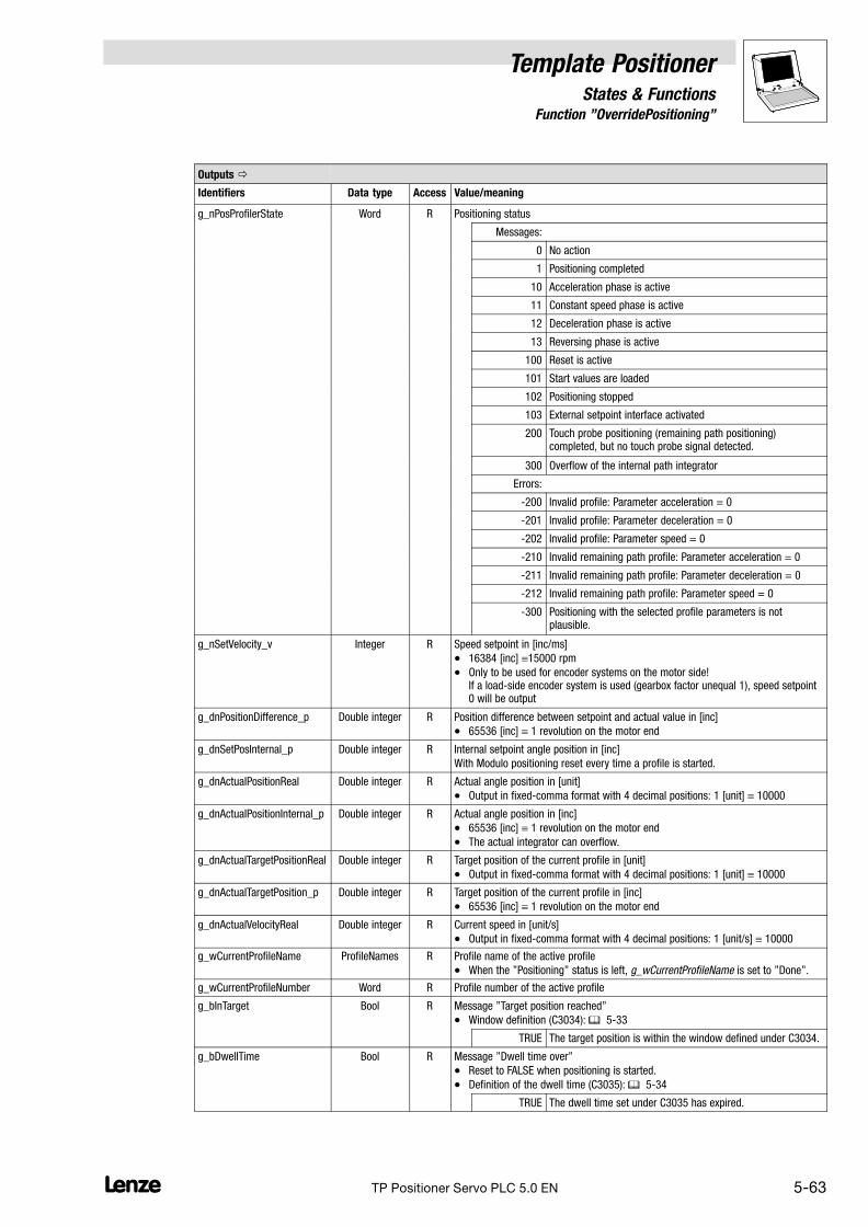
Template PositionerStates & Functions
5.6.5 Function "OverridePositioning"
5−63L TP Positioner Servo PLC 5.0 EN
Outputs �
Identifiers Data type Access Value/meaning
g_nPosProfilerState Word R Positioning status
Messages:
0 No action
1 Positioning completed
10 Acceleration phase is active
11 Constant speed phase is active
12 Deceleration phase is active
13 Reversing phase is active
100 Reset is active
101 Start values are loaded
102 Positioning stopped
103 External setpoint interface activated
200 Touch probe positioning (remaining path positioning)completed, but no touch probe signal detected.
300 Overflow of the internal path integrator
Errors:
−200 Invalid profile: Parameter acceleration = 0
−201 Invalid profile: Parameter deceleration = 0
−202 Invalid profile: Parameter speed = 0
−210 Invalid remaining path profile: Parameter acceleration = 0
−211 Invalid remaining path profile: Parameter deceleration = 0
−212 Invalid remaining path profile: Parameter speed = 0
−300 Positioning with the selected profile parameters is notplausible.
g_nSetVelocity_v Integer R Speed setpoint in [inc/ms]
� 16384 [inc] 15000 rpm
� Only to be used for encoder systems on the motor side! If a load−side encoder system is used (gearbox factor unequal 1), speed setpoint0 will be output
g_dnPositionDifference_p Double integer R Position difference between setpoint and actual value in [inc]
� 65536 [inc] 1 revolution on the motor end
g_dnSetPosInternal_p Double integer R Internal setpoint angle position in [inc]
With Modulo positioning reset every time a profile is started.
g_dnActualPositionReal Double integer R Actual angle position in [unit]
� Output in fixed−comma format with 4 decimal positions: 1 [unit] 10000
g_dnActualPositionInternal_p Double integer R Actual angle position in [inc]
� 65536 [inc] 1 revolution on the motor end
� The actual integrator can overflow.
g_dnActualTargetPositionReal Double integer R Target position of the current profile in [unit]
� Output in fixed−comma format with 4 decimal positions: 1 [unit] 10000
g_dnActualTargetPosition_p Double integer R Target position of the current profile in [inc]
� 65536 [inc] 1 revolution on the motor end
g_dnActualVelocityReal Double integer R Current speed in [unit/s]
� Output in fixed−comma format with 4 decimal positions: 1 [unit/s] 10000
g_wCurrentProfileName ProfileNames R Profile name of the active profile
� When the "Positioning" status is left, g_wCurrentProfileName is set to "Done".
g_wCurrentProfileNumber Word R Profile number of the active profile
g_bInTarget Bool R Message "Target position reached"
� Window definition (C3034): � 5−33
TRUE The target position is within the window defined under C3034.
g_bDwellTime Bool R Message "Dwell time over"
� Reset to FALSE when positioning is started.
� Definition of the dwell time (C3035): � 5−34
TRUE The dwell time set under C3035 has expired.

5.6.5 Function "OverridePositioning"
Template PositionerStates & Functions
5−64 LTP Positioner Servo PLC 5.0 EN
Outputs �
Identifiers Value/meaningAccessData type
g_bProfileBusy Bool R Message "Positioning is active"
TRUE Positioning is active.
TRUE(pulse)
g_bProfileBusy and g_bProfileDone are set to TRUE for a shorttime if target and start position are identical at the start ofabsolute positioning and positioning has therefore not beenstarted.
g_bProfileDone Bool R Message "Positioning has been completed"
TRUE Positioning has been completed.
TRUE(pulse)
g_bProfileDone and g_bProfileBusy are set to TRUE for a shorttime if target and start position are identical at the start ofabsolute positioning and positioning has therefore not beenstarted.
Parameters
Code Data type Access Info
Sub−code Possible settings Pre−setting
C3034 R / W Message window "Target position reached"
� Window definition: � 5−33
0 {1 unit} 65535 0 unit
C3035 R / W Dwell time
� Definition of the dwell time: � 5−34
0 {1 ms} 65535 50 ms
C3037 R / W Mode S−profile generation
0 Run−time−optimised 0
1 S−profile−optimised
� Requires a much longer processing time
� Further information � 7−1
C3038 R / W Activation of deceleration override
0 Deceleration override deactivated 0
1 The override deceleration (value at the inputnAccoverride_a referred to the maximum de-celeration) is accepted once when the profileis started.
Profile parameters
Code Data type Access Info
Sub−code Possible settings Pre−setting
C3100 R / W Parameter "Position" for positioning profile 1 ... n
1 ... n −214000.0000 {0.0001 unit} 214000.0000
C3200 R / W Parameter "Speed" for positioning profile 1 ... n
1 ... n 0.0001 {0.0001 unit/s} 214000.0000
C3300 R / W Parameter "Acceleration" for positioning profile 1 ... n
1 ... n 0.0001 {0.0001 unit/s2} 214000.0000
C3400 R / W Parameter "Deceleration" for positioning profile 1 ... n
1 ... n 0.0001 {0.0001 unit/s2} 214000.0000
C3500 R / W Parameter "Dwell time" for positioning profile 1 ... n
1 ... n 0.0000 {0.0001 unit/s} 214000.0000
C3600 R / W Parameter "Jerk time" for positioning profile 1 ... n
1 ... n 0.000 {0.001 s} 10.000

Template PositionerStates & Functions
5.6.5 Function "OverridePositioning"
5−65L TP Positioner Servo PLC 5.0 EN
Profile generator modes
Standard positioning: See function StandardPositioning. (� 5−38)
Remaining path positioning with touch probe: See function TouchProbePositioning. (� 5−50)
Positioning start
Positioning is started as follows:
1. Set g_bPositioningEnable from FALSE to TRUE to change from "StandBy" to "Positioning".
2. Select the positioning mode via g_byPositioningMode.
3. Transfer the profile name of the standard positioning profile, e.g. "Profile2" to the variableg_wMotionProfileNumber.
– The corresponding positioning profile will be processed immediately.
Profile change during positioning (override)
"Override" means a change of profile parameters and their acceptance during positioning.
The geometry of the traversing profile changes through an override to ensure exact positioning evenif the speed is changed during positioning (speed override):
v [m/s]
�
�
� �tt [s]
Fig. 5−14 Override (here: speed override)� Speed is reduced during positioning.� The defined position can only be reached if the missing area is "added" to the profile.� The reduced speed results in a longer positioning process (�t).
Note!
Speed and acceleration override have no effect during deceleration because the target positionwould not be reached if the selected deceleration ramp was changed during deceleration!
During positioning, the braking distance is continuously calculated from the current speed and theselected deceleration ramp. If the braking distance equals the remaining path to the target positionthe drive brakes along the selected deceleration ramp.

5.6.5 Function "OverridePositioning"
Template PositionerStates & Functions
5−66 LTP Positioner Servo PLC 5.0 EN
Definition of the reference values for override
The reference for the override values is defined under g_byOverrideMode:
v [m/s]
�t t [s]
vprofile
50 % v
vmax
profile
v [m/s]
�t t [s]
vprofile
50 % v
vmax
max
g_byOverrideMode = 0
g_byOverrideMode = 1
g_nVelOverride_a = 8192 (50 %)
g_nVelOverride_a = 8192 (50 %)
Fig. 5−15 Definition of the reference value for override (here: speed override)
Tip!
Override mode "1" can be used to reduce the clock pulse rate of the tool, e.g. for machine set−up.In this mode, the profile remains unchanged, only profile processing takes longer.

Template PositionerStates & Functions
5.6.5 Function "OverridePositioning"
5−67L TP Positioner Servo PLC 5.0 EN
Execution of override
� The speed override is activated by setting g_bExecuteVelOverride to TRUE.
� The acceleration override is activated by setting g_bExecuteAccOverride to TRUE.
� The reference for the override values is defined via g_byOverrideMode.
� The speed override is selected via the input g_nVelOverride_a, the acceleration override viathe input g_nAccOverride_a:
"Override"parameters
Identifiers Data type Info/possible settings
g_nVelOverride_a Integer 1 ... 16384 Speed
� Speed overrides are only effective during acceleration and constant traversing(trapezium).
� If a speed override is executed during constant traversing the drive deceleratesor accelerates until the new speed is reached. The current profile parameters areused for acceleration/deceleration. If an acceleration override is activated inaddition the drive accelerates with the new acceleration value.
g_byOverrideMode = 0
� Value refers to vmax (selected max. speed)
� 16384 vmax
g_byOverrideMode = 1
� Value refers to vprofile (speed of the active profile)
� 16384 vprofile
g_nAccOverride_a Integer 1 ... 16384 Acceleration
� Acceleration overrides are only effective in the acceleration phase.
g_byOverrideMode = 0
� Value refers to amax (selected max. acceleration)
� 16384 amax
g_byOverrideMode = 1
� Value refers to aprofile (acceleration of the active profile)
� 16384 aprofile

5.6.5 Function "OverridePositioning"
Template PositionerStates & Functions
5−68 LTP Positioner Servo PLC 5.0 EN
Code C3038 can be used to activate the deceleration override. If the deceleration override isactivated (C3038= 1), the override deceleration (value at the input nAccoverride_a referred to themaximum deceleration) is accepted once when the profile is started. During the subsequent courseof the positioning process, the profile deceleration will not be changed again.
Parameters
Code Data type Access Info
Sub−code Possible settings Pre−setting
C3038 R / W Activation of deceleration override
0 Deceleration override deactivated 0
1 The override deceleration (value at the inputnAccoverride_a referred to the maximum de-celeration) is accepted once when the profileis started.
Definition of the 100% reference for decele-ration override parameters:
� C3038 = 0: 16384 100 % Accmaxfrom the axis parameters
� C3038 = 1: 16384 100 % Dec fromthe profile parameters
Tip!
If an override is activated changes at the inputs g_nVelOverride_a or g_nAccOverride_a will havea direct effect on the profile.
If the override is deactivated by resetting g_bExecuteVelOverride to FALSE org_bExecuteAccOverride to FALSE profile processing will be completed with the current speed value.
t
vvmax
�
75 %
g_bExecuteVelOverride
g_nVelOverride_a 12288 8192
� �
50 %
g_byOverrideMode = 0
Fig. 5−16 Override (here: speed override)� Speed override is activated (g_bExecuteVelOverride = TRUE);
Speed is reduced to 75 % of vmax (g_nVelOverride_a = 12288)� Speed is once again reduced to 50% of vmax (g_nVelOverride_a = 8192)� Speed override is deactivated (g_bExecuteVelOverride = FALSE)

Template PositionerStates & Functions
5.6.5 Function "OverridePositioning"
5−69L TP Positioner Servo PLC 5.0 EN
Example sequencer "OverrideSequence"
PROGRAM OverrideSequence(* Example of a positioning sequence *)(* in mode Absolute with 3 destinations *)
VAR_INPUTSFCInit:BOOL; (* TRUE: The sequence is defined *)
(* in step Init *)END_VAR
Input action Homing:
(* Ensure that the reference is known in mode Absolute *)
(* No reference ? *)IF NOT g_bHomePositionAvailable THEN
(* Reset of status positioning *)g_bPositioningEnable:=FALSE;
(* Homing start *)g_bHomingStart:=TRUE;
END_IF
Output action Homing:
(* First, jump to template status positioning *)g_bPositioningEnable:=TRUE;
Transition ReferenceOk:
Input action Step1:
(* Set positioning mode to Absolute *)(* −−> Also possible is 0 instead of Absolute *)g_byPositioningMode:=Absolute;
(* Copy 1st profile to g_wMotionProfileNumber *)(* −−> Also possible is the corresponding number in enum list *)g_wMotionProfileNumber:=Profile7;

5.6.5 Function "OverridePositioning"
Template PositionerStates & Functions
5−70 LTP Positioner Servo PLC 5.0 EN
Transition Trans1:
Input actionStep2:
(* Override mode limits the override values to their maximum axis parameters *)g_byOverrideMode:= 0;
(* Activation of speed override *)g_bExecuteVelOverride:=TRUE;
(* Activation of acceleration override *)g_bExecuteAccOverride:=TRUE;
Output action Step2:
(* Deactivation of speed override *)g_bExecuteVelOverride:=FALSE;
(* Deactivation of acceleration override *)g_bExecuteAccOverride:=FALSE;
Transition Trans2:
Input action Step3:
(* Set positioning mode to Absolute *)(* −−> Also possible is 0 instead of Absolute *)g_byPositioningMode:=Absolute;
(* Copy 3rd profile to g_wMotionProfileNumber *)(* −−> Also possible is the corresponding number in enum list *)g_wMotionProfileNumber:=Profile8;
Transition Trans3:

Template PositionerStates & Functions
5.6.6 Function "ChangeProfileInterface"
5−71L TP Positioner Servo PLC 5.0 EN
5.6.6 Function "ChangeProfileInterface"
With this template function the parameters of a profile can be changed.
Parameter
Inputs Outputs
g_bChangeProfile
g_wChangeProfile
ChangeProfileInterface
g_dnChangePosition
g_dnChangeVelocity
g_dnChangeAcceleration
g_dnChangeDeceleration
Profile n
Profile ...
Profile 2
Profile 1
v
t
g_dnChangeFinalVelocity
g_dnChangeJerkTime
� Inputs/outputs �
Identifiers Data type Access Info/possible settings
g_bChangeProfile Bool R / W Writing of profiles
� Possible with "Stand By", "Homing", "Manual Jog" and "PostioningOperation".
� If writing has been successful, g_bChangeProfile and g_wChangeProfile will beset to "0".
FALSE TRUE The profile indicated in g_wChangeProfile is written with theparameters indicated under
� g_dnChangePosition,
� g_dnChangeVelocity,
� g_dnChangeAcceleration and
� g_dnChangeDeceleration
� g_dnChangeFinalVelocity
� g_dnChangeJerkTime
.
g_wChangeProfile ProfileNames R / W Name of the profile which is written with a FALSE−TRUE transition atg_bChangeProfile.
� If writing with g_bChangeProfile has been successfulg_wChangeProfile is set to "0".
� Inputs
Identifiers Data type Access Info/possible settings
g_dnChangePosition Double integer R / W Parameter "Position" for a profile change with g_bChangeProfile
� In [unit] * 10000
g_dnChangeVelocity Double integer R / W Parameter "Speed" for a profile change with g_bChangeProfile
� In [unit/s] * 10000
� 0 no parameter change in the target profile.
g_dnChangeAcceleration Double integer R / W Parameter "Acceleration" for a profile change with g_bChangeProfile
� In [unit/s2] * 10000
� 0 no parameter change in the target profile.
g_dnChangeDeceleration Double integer R / W Parameter "Deceleration" for a profile change with g_bChangeProfile
� In [unit/s2] * 10000
� 0 no parameter change in the target profile.

5.6.6 Function "ChangeProfileInterface"
Template PositionerStates & Functions
5−72 LTP Positioner Servo PLC 5.0 EN
� Inputs
Identifiers Info/possible settingsAccessData type
g_dnChangeFinalVelocity Double integer R / W Parameter "Final speed" for a profile change with g_bChangeProfile
� In [unit/s] * 10000
� 0 no parameter change in the target profile.
g_dnChangeJerkTime Double integer R / W Parameter "Jerk time" for a profile change with g_bChangeProfile
� In [ms]
� 0 no jerk limitation.

Template PositionerStates & Functions
5.6.7 Function "PositionCorrection"
5−73L TP Positioner Servo PLC 5.0 EN
5.6.7 Function "PositionCorrection"
This template function is used to compensate linearity errors at feed mechanisms (e.g. leadscrews)or measuring systems by means of a table of correction values.
Parameter
Inputs Outputs
g_bPosCorrectionEnableg_nPosCorrectionState
PositionCorrection
Correction table:
C3090/1...n
C3091/1...n
measure position
measure difference
Position
Difference from setpoint
100 200 300 400 500 600
g_bNewCorrectionValuesValid
Diff
ere
nce
Position
g_dnCorrectionValue_p
� Inputs
Identifiers Data type Access Info/possible settings
g_bPosCorrectionEnable Bool R / W Activation of position correction
TRUE Position correction is activated.
Outputs �
Identifiers Data type Access Value/meaning
g_nPosCorrectionState Integer R Status of position correction
0 Ok
10 Number of measured values is no 2n−value, the correctivecalculation is not precise.
20 Position correction is deactivated.
(g_bPosCorrectionEnable = FALSE)
g_bNewCorrectionValuesValid Bool R Message output "Calculation has been completed"
FALSE Calculation of correction values has not been completed yet.
� Do not start positioning while calculation is in process.
TRUE Calculation of correction values has been completed.
g_dnCorrectionValue_p Double integer R Correction value (interpolated position correction value)

5.6.7 Function "PositionCorrection"
Template PositionerStates & Functions
5−74 LTP Positioner Servo PLC 5.0 EN
Parameters
Code Data type Access Info
Sub−code Possible settings Pre−setting
C3090 R / W Correction position 1 ... n
1 ... n −214000.0000 {0.0001 unit} 214000.0000 0 unit
C3091 R / W Position correction value 1 ... n
1 ... n −214000.0000 {0.0001 unit} 214000.0000 0 unit
Creation of the measured−value table
For this, different measuring points are approached along the axis and the deviations from theselected setpoint positions are measured by means of a reference measuring system (e.g. lasermeasuring system):
Position [unit]
Difference from setpoint [unit]
100 200 300 400 500 600
0
-2
-4
+2
+4
Fig. 5−17 Measurement of position errors at different measuring points
The measured values can be entered into a table:
MeasurementNo.
Approached setpoint position
�set
Deviation from the setpoint position
��= �act − �set
1 100 [unit] −1.00 [unit]
2 230 [unit] 0.00 [unit]
3 400 [unit] 1.80 [unit]
4 480 [unit] 2.00 [unit]
... ... ...
n ___ [unit] ___ [unit]
Definition of the number of measuring points
The number of available sub−codes and thus the number of measuring points is defined under thevariable C_byNumberOfPosCorrectionValues.(Object Organizer/register Resources � folder Global variables � folder TemplateInterface �variable list VarTemplateSettings (CONSTANT))
� The variable has been preset to �16", i.e. the sub−codes for 16 measuring points are alreadyavailable.
� Only 2n−values are permissible, i.e. 2, 4, 8, 16, 32, ...
� If you change the number of profiles, the corresponding sub−codes will be available after thecompilation.

Template PositionerStates & Functions
5.6.7 Function "PositionCorrection"
5−75L TP Positioner Servo PLC 5.0 EN
Entry of measured values
The measured values of the correction table can be transferred to the sub−codes of parametersC3090 and C3091:
MeasurementNo.
Approached setpoint position
�set
Deviation from the setpoint position
��= �act − �set
C3090 C3091
Sub−code
Parameters* Sub−code
Parameters*
1 100 [unit] 1 1000000 −1.00 [unit] 1 −10000
2 230 [unit] 2 2300000 0.00 [unit] 2 0
3 400 [unit] 3 4000000 1.80 [unit] 3 18000
4 480 [unit] 4 4800000 2.00 [unit] 4 20000
... ... ... ... ... ... ...
n ___ [unit] n ___ ___ [unit] n ___
* The parameters are entered in fixed−comma format with 4 decimal positions
The Parameter monitor can be used to enter the measured−values into the correspondingsub−codes:
1. Ensure that you are logged in.
2. Use the Parameter monitor (Object Organizer � register Resources) and select the folderIndividual IEC1131 codes � POUPositionCorrection.
3. Enter the corresponding values into the code.
Caution!
A repeated program download overwrites the code settings with the initialisation values!
Notes
� The measuring positions need not be equidistant. You need not start at measuring position"0".
� The measuring positions have to be entered in ascending order.
� Only 2n−values are permissible for the number of measuring points, i.e. 16, 32, 64, etc.
� The computing time increases linearly with the number of measuring points. To savecomputing time, an adequate number of measuring points should be selected underC_byNumberOfPosCorrectionValues.
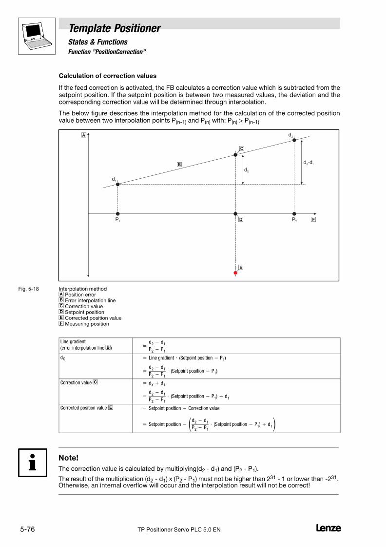
5.6.7 Function "PositionCorrection"
Template PositionerStates & Functions
5−76 LTP Positioner Servo PLC 5.0 EN
Calculation of correction values
If the feed correction is activated, the FB calculates a correction value which is subtracted from thesetpoint position. If the setpoint position is between two measured values, the deviation and thecorresponding correction value will be determined through interpolation.
The below figure describes the interpolation method for the calculation of the corrected positionvalue between two interpolation points P(n−1) and P(n) with: P(n) > P(n−1)
d1
d2
d -2 d1
dX
P1 P2
�
�
�
�
�
�
Fig. 5−18 Interpolation method� Position error� Error interpolation line� Correction value Setpoint position Corrected position value� Measuring position
Line gradient
(error interpolation line �) �d2 � d1
P2 � P1
dX � Line�gradient � (Setpoint�position � P1)
�d2 � d1
P2 � P1
� (Setpoint�position � P1)
Correction value � � dX � d1
�d2 � d1
P2 � P1
� (Setpoint�position � P1) � d1
Corrected position value � Setpoint�position � Correction�value
� Setpoint�position ��d2 � d1
P2 � P1
� (Setpoint�position � P1) � d1�
Note!
The correction value is calculated by multiplying(d2 − d1) and (P2 − P1).
The result of the multiplication (d2 − d1) x (P2 − P1) must not be higher than 231 − 1 or lower than −231.Otherwise, an internal overflow will occur and the interpolation result will not be correct!

Template PositionerStates & Functions
5.7 Parallel processes "PosFunctions"
5−77L TP Positioner Servo PLC 5.0 EN
5.7 Parallel processes "PosFunctions"
The following function runs in parallel to the status machine and can therefore be executed in everystatus:
Function Info
TemplateControl Trouble−shooting and status check � 5−78

5.7.1 Function "TemplateControl"
Template PositionerStates & Functions
5−78 LTP Positioner Servo PLC 5.0 EN
5.7.1 Function "TemplateControl"
This template function is used to enter cross−function settings and check the status messages of thetemplate.
Parameter
Inputs Outputs
g_bErrorReset
g_bUserQuickstop
TemplateControl
C3017
C3018
C3030
C3031
C3034
C3035
C3040
C3041
C3042
C3050
C3051
C3052
C3053
C3056
C3057
C3061
C3063
C3064
C3065
C3066
velocity threshold
hysteresis for zero speed detection
for zero speed detection
following error warning limit
following error limit
target window
dwell time
positive software limit
negative software limit
actual position in [inc]
actual position in [unit]
no. of actual active profile
actual positioning velocity
actual absolute target position or distance
target position or distance in [unit]
position resolution
minimal profile velocity in [unit/s]
minimal profile acceleration/deceleration in [unit/s²]
positioning state
positioning profiler state
SW-limits control mode
Start
StandBy
Init
Positioning
Homing
Trouble
ManualJog
g_byOperationState
g_wErrorType
g_wErrorNumber
g_bGlobalError
g_bVelocityLowerC3017
g_bErrorSet
g_bPositioningEnable
g_bLimitSwitchNeg
g_bLimitSwitchPos
g_bInTarget
g_bDwellTime
g_wCurrentProfileName
g_wCurrentProfileNumber
� Inputs
Identifiers Data type Access Info/possible settings
g_bPositioningEnable Bool R / W Enabling positioning
TRUE Change to "Positioning"
FALSE Cancellation of positioning, change to "StandBy"
g_bErrorReset Bool R / W Reset of template−internal and user−defined errors
� If the variable g_bErrorResetEqTripReset is set to TRUE a TRIP reset will becarried out together with the error reset. See variable list "VarTemplateSettings(constant)".
TRUE Error reset
g_bErrorSet Bool R / W Change to "Error" if one of the messages configured through the FB FWM is active.
� The variables can be set by means of the "Set" instruction.
� They are automatically reset to FALSE by the template.
TRUE Change to "Trouble"
g_bUserQuickstop Bool R / W User quick stop (quick stop of the drive system)
TRUE Activates user quick stop
g_bLimitSwitchNeg Bool R / W Input for limit switch (negative)
TRUE Limit switch reached

Template PositionerStates & Functions
5.7.1 Function "TemplateControl"
5−79L TP Positioner Servo PLC 5.0 EN
� Inputs
Identifiers Info/possible settingsAccessData type
g_bLimitSwitchPos Bool R / W Input for limit switch (positive)
TRUE Limit switch reached
Outputs �
Identifiers Data type Access Value/meaning
g_byOperationState OperationMode R Display of the main template states
0 Status "StandBy"
� Status from which the drive changes to all other states.
1 Status "Trouble"
20 Status "ManualJog"
30 Status "Homing"
40 Status "Positioning"
g_wErrorType ErrorReaction R Display of the error type
0 Error (TRIP)
1 Message
2 Warning
3 Error with quick stop of the drive system (FAIL−QSP)
4 Ready, drive is ready (no error − RDY)
g_wErrorNumber ErrorCode R Display of the error name
� See Object Organizer:Register Data types � folder UserDataTypes � ErrorCode (ENUM)
g_bGlobalError Bool R Message "Error"
TRUE An error has occurred and the template has changed to"Trouble".
g_bVelocityLowerC3017 Bool R Display if speed < threshold value for zero speed detection (C3017)
TRUE Speed < threshold for zero speed detection
g_wCurrentProfileName ProfileNames R Profile name of the active profile
� When the "Positioning" status is left, g_wCurrentProfileName is set to "Done".
g_wCurrentProfileNumber Word R Profile number of the active profile
g_bInTarget Bool R Message "Target position reached"
� Window definition (C3034): � 5−33
TRUE The target position is within the window defined under C3034.
g_bDwellTime Bool R Message "Dwell time over"
� Reset to FALSE when positioning is started.
� Definition of the dwell time (C3035): � 5−34
TRUE The dwell time set under C3035 has expired.

5.7.1 Function "TemplateControl"
Template PositionerStates & Functions
5−80 LTP Positioner Servo PLC 5.0 EN
Parameters
Code Data type Access Info
Sub−code Possible settings Pre−setting
C3017 R / W Threshold for zero speed detection
0.0000 {0.0001 unit/s} 214000.0000 0 unit/s
C3018 R / W Hysteresis for zero speed detection
0.00 {0.01 %} 100.00 0.10 %
C3030 R / W Following error warning limit
0.0000 {0.0001 unit} 214000.0000 0 unit
C3031 R / W Following error limit
0.0000 {0.0001 unit} 214000.0000 0 unit
C3034 R / W Message window "Target position reached"
� Window definition: � 5−33
0 {1 unit} 65535 0 unit
C3035 R / W Dwell time
� Definition of the dwell time: � 5−34
0 {1 ms} 65535 50 ms
C3040 R / W Positive software limit position
� The value entered under C3040 must not be lower than the value in C3041.Otherwise, FAIL−QSP is activated and the drive changes to "Trouble".
−214000.0000 {0.0001 unit} 214000.0000
0 = Software limit position deactivated
0 unit
C3041 R / W Negative software limit position
� The value entered under C3041 must not be higher than the value in C3040.Otherwise, FAIL−QSP is activated and the drive changes to "Trouble".
−214000.0000 {0.0001 unit} 214000.0000
0 = Software limit position deactivated
0 unit
C3042 R / W Mode of software limit position monitoring � 5−83
0 Current setpoint position + selected directionof motion
0
1 Current actual position
Note: The acceptance of new settings under C3030, C3031, C3034, C3035, C3040 and C3041 requires a status change to "StandBy"!
Tip!
The [unit] is to be entered in fixed−comma format with 4 decimal positions, i.e. 1 [unit] 10000.

Template PositionerStates & Functions
5.7.1 Function "TemplateControl"
5−81L TP Positioner Servo PLC 5.0 EN
The following parameters can only be read:
Parameters (only display)
Code Data type Access Info
C3050 R Current position in [inc]
C3051 R Current position in [unit]
C3052 R Number of the active positioning profile
C3053 R Current speed in [unit/s]
C3056 R Current absolute target position or distance in [inc]
C3057 R Target position or distance in [unit]
C3061 R Position resolution in [inc/unit]
C3063 R Minimum profile speed in [unit/s]
C3064 R Minimum acceleration/deceleration in [unit/s2]
C3065 R Positioning status
0
1
20
30
40
StandBy
Trouble
ManualJog
Homing
Positioning
C3066 R Profile generator status
157001578815789157901579815799158001600016001160101601116012160131610016101161021610316300
InvProfParProfAuxVelEq0ProfAuxDecEq0ProfAuxAccEq0ProfVelEq0ProfDecEq0ProfAccEq0NoActionPosDoneAccelerationConstSpeedDecelerationReversingResetActiveLoadStartValAbortActiveExtSetValNoTPDetected
5.7.1.1 Evaluation of user quick stops (UserQuickstop)
During traversing, quick stop can be activated by setting g_bUserQuickstop = TRUE, i.e. the drivebrakes along the set quick stop ramp to standstill and changes to "StandBy".
� The quick stop ramp can be set under the corresponding motor control parameters (e.g.C0105 with the 9300 Servo PLC).

5.7.1 Function "TemplateControl"
Template PositionerStates & Functions
5−82 LTP Positioner Servo PLC 5.0 EN
5.7.1.2 Monitoring of following errors
The following error monitoring is configured under the parameters C3030 and C3031.
Note!
The acceptance of new settings in C3030/C3031 requires a status change to "StandBy"!
Following error warning limit (C3030)
If the difference between setpoint and actual position is higher than the value selected under C3030a following error warning is activated.
v [m/s]
t [s]
� � �
A B
Fig. 5−19 Following errorA Setpoint profileB Processed profile� The drive decelerates, a difference occurs between setpoint and actual position.� The difference between setpoint and actual position is higher than the value selected under C3030 � followingerror.� Setpoint profile has been processed.
� If "Positioning" is active processing of the next profile will not be started and the variableg_wMotionProfileNumber will remain "Active" until the following error has been removed(actual position monitoring).g_wMotionProfileNumber will only be set to "Done" if the following error has been removedand profile processing has been completed.
� In all other states, the following error warning will only be indicated in the variablesg_byErrorType and g_wErrorNumber.
Following error limit (C3031)
If the difference between setpoint and actual position is higher than the value selected under C3031the drive brakes along the set quick stop ramp to standstill and changes to "Trouble".
� The quick stop ramp can be set under the corresponding motor control parameters (e.g.C0105 with the 9300 Servo PLC).
� Following errors are monitored in all movement states of the drive.
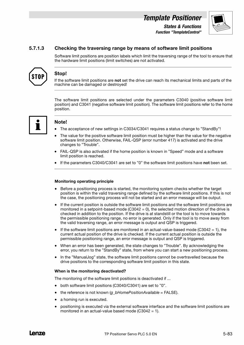
Template PositionerStates & Functions
5.7.1 Function "TemplateControl"
5−83L TP Positioner Servo PLC 5.0 EN
5.7.1.3 Checking the traversing range by means of software limit positions
Software limit positions are position labels which limit the traversing range of the tool to ensure thatthe hardware limit positions (limit switches) are not activated.
Stop!
If the software limit positions are not set the drive can reach its mechanical limits and parts of themachine can be damaged or destroyed!
The software limit positions are selected under the parameters C3040 (positive software limitposition) and C3041 (negative software limit position). The software limit positions refer to the homeposition.
Note!
� The acceptance of new settings in C3034/C3041 requires a status change to "StandBy"!
� The value for the positive software limit position must be higher than the value for the negativesoftware limit position. Otherwise, FAIL−QSP (error number 417) is activated and the drivechanges to "Trouble".
� FAIL−QSP is also activated if the home position is known in "Speed" mode and a softwarelimit position is reached.
� If the parameters C3040/C3041 are set to "0" the software limit positions have not been set.
Monitoring operating principle
� Before a positioning process is started, the monitoring system checks whether the targetposition is within the valid traversing range defined by the software limit positions. If this is notthe case, the positioning process will not be started and an error message will be output.
� If the current position is outside the software limit positions and the software limit positions aremonitored in a setpoint−based mode (C3042 = 0), the selected motion direction of the drive ischecked in addition to the position. If the drive is at standstill or the tool is to move towardsthe permissible positioning range, no error is generated. Only if the tool is to move away fromthe valid traversing range, an error message is output and QSP is triggered.
� If the software limit positions are monitored in an actual−value−based mode (C3042 = 1), thecurrent actual position of the drive is checked. If the current actual position is outside thepermissible positioning range, an error message is output and QSP is triggered.
� When an error has been generated, the state changes to "Trouble". By acknowledging theerror, you return to the "StandBy" state, from where you can start a new positioning process.
� In the "ManualJog" state, the software limit positions cannot be overtravelled because thedrive positions to the corresponding software limit position in this state.
When is the monitoring deactivated?
The monitoring of the software limit positions is deactivated if ...
� both software limit positions (C3040/C3041) are set to "0".
� the reference is not known (g_bHomePositionAvailable = FALSE).
� a homing run is executed.
� positioning is executed via the external software interface and the software limit positions aremonitored in an actual−value based mode (C3042 = 1).
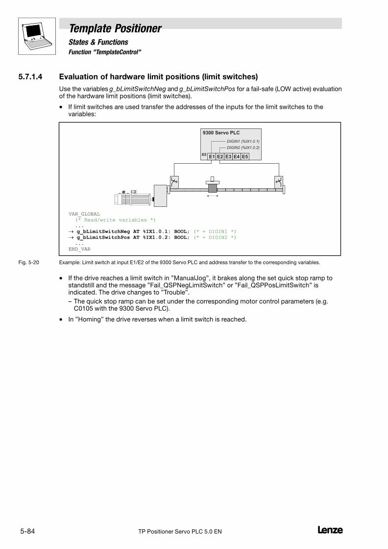
5.7.1 Function "TemplateControl"
Template PositionerStates & Functions
5−84 LTP Positioner Servo PLC 5.0 EN
5.7.1.4 Evaluation of hardware limit positions (limit switches)
Use the variables g_bLimitSwitchNeg and g_bLimitSwitchPos for a fail−safe (LOW active) evaluationof the hardware limit positions (limit switches).
� If limit switches are used transfer the addresses of the inputs for the limit switches to thevariables:
E1 E2 E3 E4
9300 Servo PLC
X5E5
DIGIN1 (%IX1.0.1)
DIGIN2 (%IX1.0.2)
VAR_GLOBAL (* Read/write variables *) ... � g_bLimitSwitchNeg AT %IX1.0.1: BOOL; (* = DIGIN1 *) � g_bLimitSwitchPos AT %IX1.0.2: BOOL; (* = DIGIN2 *) ... END_VAR
Fig. 5−20 Example: Limit switch at input E1/E2 of the 9300 Servo PLC and address transfer to the corresponding variables.
� If the drive reaches a limit switch in "ManualJog", it brakes along the set quick stop ramp tostandstill and the message "Fail_QSPNegLimitSwitch" or "Fail_QSPPosLimitSwitch" isindicated. The drive changes to "Trouble".
– The quick stop ramp can be set under the corresponding motor control parameters (e.g.C0105 with the 9300 Servo PLC).
� In "Homing" the drive reverses when a limit switch is reached.

Template Positioner6 Program Organisation Units (POUs)
6−1L TP Positioner Servo PLC 5.0 EN
6 Program Organisation Units (POUs)
The template includes the following POUs. They can be adapted and extended:
� The POU UserErrors (PRG) to eliminate user−defined errors.
� The POU UserInterface (PRG) to program the positioning logic. (� 6−3)
6.1 Troubleshooting − POU "UserErrors"
This POU is used to eliminate user−defined errors by means of the function block FWM.
Tip!
The FB FWM is used to transmit error messages to the PLC.
� With the FB it is possible to activate TRIP, FAIL−QSP, message or warning in the PLC directlyby the PLC program.
The POU UserErrors (PRG) can be found in the register Organization units � folderUserExtensions � folder UserPOUs of the Object Organizer and already includes an examplenetwork:
Fig. 6−1 Example network in the POU "UserErrors (PRG)" with an instance of the FB FWM
� In the example network, bExampleError is the variable for error detection, i.e. this variableactivates the configured error by means of a high signal at the input bExecute of the FB FWM.
� If an error occurs the global template variable g_bErrorSet is set to TRUE.
� The error type is set via the input byTypeOfFault of the FB FWM(0 = TRIP, 1 = message, 2 = warning, 3 = switched off, 4 = FAIL−QSP).
– With "TRIP" (byTypeOfFault = 0), the template will be set to "Trouble".
– With "message", "warning" and "FAIL−QSP" (byTypeOfFault = 1, 2 or 4), the template willremain in the status that was active when the error was activated.
– If you want the template to be set to "Trouble" with "message", "warning" or "FAIL−QSP",also set the global variable g_bErrorSet (see network example in the POU "UserErrors").
– The template status "Trouble" must be actively reset to return to "StandBy" (e.g. by settingthe global variable g_bErrorSet).
� The error numbers between 500 ... 999 are set via the input wFaultNumber of the FB FWM.
� It is also possible to enter a text message for every error number using the data typeErrorCode (ENUM). (� 7−13)
If the error detection bExampleError = TRUE, the PLC activates "FAIL−QSP" and the error number"500" is entered into the history buffer of the PLC.

6 Program Organisation Units (POUs)
Template Positioner
6−2 LTP Positioner Servo PLC 5.0 EN
Tip!
Use this example network as basis and create new networks by copy & paste:
Fig. 6−2 Extended POU "UserErrors (PRG)" with two networks for troubleshooting
� If you add new networks do not forget to adapt the list of text messages in data typeErrorCode (ENUM) accordingly:
TYPE ErrorCode : ( NoError:=0, CCr:=71, ... UserError1:=500, UserError2:=501 ); END_TYPE
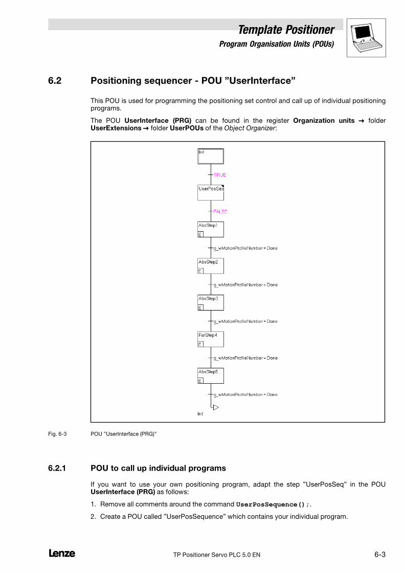
Template Positioner6 Program Organisation Units (POUs)
6−3L TP Positioner Servo PLC 5.0 EN
6.2 Positioning sequencer − POU "UserInterface"
This POU is used for programming the positioning set control and call up of individual positioningprograms.
The POU UserInterface (PRG) can be found in the register Organization units � folderUserExtensions � folder UserPOUs of the Object Organizer:
Fig. 6−3 POU "UserInterface (PRG)"
6.2.1 POU to call up individual programs
If you want to use your own positioning program, adapt the step "UserPosSeq" in the POUUserInterface (PRG) as follows:
1. Remove all comments around the command UserPosSequence();.
2. Create a POU called "UserPosSequence" which contains your individual program.

6 Program Organisation Units (POUs)
Template Positioner
6−4 LTP Positioner Servo PLC 5.0 EN
6.2.2 Use of the positioning sequencer
The POU UserInterface (PRG) already includes a sequencer for five positioning profiles. It can beused as a basic element for more complex controls.
Principle of the positioning sequencer in the POU UserInterface (PRG)
The principle of the positioning sequencer is the transfer of a traversing profile to the variableg_wMotionProfileNumber as well as the positioning mode to the variable g_byPositioningMode.
� Every step has an input action which defines the name of the positioning profile to betraversed and the positioning mode:
(* Statements of Step2 *)g_byPositioningMode:=Absolute;g_wMotionProfileNumber:=Profile2;
� If the profile assigned to a certain step has been traversed, the variableg_wMotionProfileNumber sends the "Done" and thus complies with the transition conditionsfor the next step of the sequencer.
� If a new profile is transferred to g_wMotionProfileNumber during the process, the currentprofile processing will be stopped and the new profile will be used.
� After the last step has been completed, the system automatically jumps back to the first stepand starts processing the sequencer again.
If you want to use the sequencer for positioning, adapt the POU UserInterface (PRG) as follows:
1. Set the transition after "UserPosSeq" TRUE to activate the following sequencer.
2. Remove all unnecessary steps or add steps to the sequencer.
3. If you have added steps to the sequencer, the input actions (profile names) of these stepsmust be adapted.
4. If you have added or removed steps, do not forget to adapt the constantC_wNumberOfMotionObjects to the corresponding number of profiles.(See chapter "Settings") (� 7−12)

Template PositionerAppendix
7.1 Technical data
7−1L TP Positioner Servo PLC 5.0 EN
7 Appendix
7.1 Technical data
� Up to 128 profiles can be parameterised
� Usable memory:
– 4.2 kbyte RAM without any profiles created.
– 400 kbyte ROM for user program
� Memory for a profile:
– 24 byte RAM (net)
– 26 byte RAM (gross; incl. profile name assignment in ENUM list)
� Memory for feed correction (template function PositionCorrection):
– 8 bytes per measuring point (4 bytes for correction position + 4 bytes for correction value)
� Task run times:
– Run−time−optimised S−profile generation (C3037 = 0):
Task Average run time Maximum run time
System task � 10 ms � 90 ms
Cyclic task (PLC_PRG) � 20 ms � 30 ms
Task1 (2 ms task) � 525 �s � 625 �s
Task2 (5 ms task) � 450 �s � 1550 �s
User task (5 ms task) � 80 �s � 750 �s
– Profile−optimised S−profile generation (C3037 = 1):
Task Average run time Maximum run time
System task � 10 ms � 90 ms
Cyclic task (PLC_PRG) � 20 ms � 30 ms
Task1 (2 ms task) � 800 �s � 900 �s
Task2 (5 ms task) � 450 �s � 1550 �s
User task (5 ms task) � 80 �s � 300 �s
� The user can add maximally 215 organisation units.
� Download time per axis: approx. 30 s
� Task 1 and task 2 are reserved for the template. The priorities must not be changed.
� Task 3 is the user task which the user can use for program extensions. The task interval isdefault set to 5 ms and cannot be reduced. The interval provides a maximum computing timeof 750 �s (run−time−optimised, C3037 = 0) and 300 �s (profile−optimised, C3037 = 1) for userfunctions. If this time is exceeded, a task overflow may occur (worst case).

7.2 Global variables
Template PositionerAppendix
7−2 LTP Positioner Servo PLC 5.0 EN
7.2 Global variables
The following variable declarations can be found in the Object Organizer/register Resources, folderGlobal variables � TemplateInterface.
7.2.1 VarChangeProfileInterface
� Inputs
Identifiers Data type Access Info/possible settings
g_dnChangePosition Double integer R / W Parameter "Position" for a profile change with g_bChangeProfile
� In [unit] * 10000
g_dnChangeVelocity Double integer R / W Parameter "Speed" for a profile change with g_bChangeProfile
� In [unit/s] * 10000
� 0 no parameter change in the target profile.
g_dnChangeAcceleration Double integer R / W Parameter "Acceleration" for a profile change with g_bChangeProfile
� In [unit/s2] * 10000
� 0 no parameter change in the target profile.
g_dnChangeDeceleration Double integer R / W Parameter "Deceleration" for a profile change with g_bChangeProfile
� In [unit/s2] * 10000
� 0 no parameter change in the target profile.
g_dnChangeFinalVelocity Double integer R / W Parameter "Final speed" for a profile change with g_bChangeProfile
� In [unit/s] * 10000
� 0 no parameter change in the target profile.
g_dnChangeJerkTime Double integer R / W Parameter "jerk time" for a profile change with g_bChangeProfile
� In [ms]
� 0 no jerk limitation.
� Inputs/outputs �
Identifiers Data type Access Info/possible settings
g_bChangeProfile Bool R / W Writing of profiles "StandBy", "Homing", "ManualJog" and "PostioningOperation"
� Possible with "StandBy" and "PositioningOperation".
� If writing has been successful, g_bChangeProfile and g_wChangeProfile will beset to "0".
FALSE TRUE The profile indicated in g_wChangeProfile is written with theparameters indicated under
� g_dnChangePosition,
� g_dnChangeVelocity,
� g_dnChangeAcceleration and
� g_dnChangeDeceleration
� g_dnChangeFinalVelocity
� g_dnChangeJerkTime
.
g_wChangeProfile ProfileNames R / W Name of the profile which is written with a FALSE−TRUE transition atg_bChangeProfile.
� If writing with g_bChangeProfile has been successfulg_wChangeProfile is set to "0".

Template PositionerAppendix
7.2 Global variables
7−3L TP Positioner Servo PLC 5.0 EN
7.2.2 VarExternalSetValues
� Inputs
Identifiers Data type Access Info/possible settings
g_bExtSetValuesEnable Bool R / W Changeover to external setpoints
TRUE The external setpoints are directly transferred to the motorcontrol:
� g_nExtMSet_a � nMSet_a
� g_nExtNSet_a � nNSet_a
� g_dnExtDeltaPos_p � dnDeltaPos_p
g_nExtMSet_a Integer R / W External setpoint for torque precontrol
g_nExtNSet_a Integer R / W External setpoint for the setpoint speed
g_dnExtDeltaPos_p Integer R / W External setpoint for the position difference
g_nNAdd_a Integer R / W Additional speed setpoint
g_nMAdd_a Integer R / W Additional setpoint for torque precontrol
7.2.3 VarHardwareSignals
� Inputs
Identifiers Data type Access Info/possible settings
g_bLimitSwitchNeg Bool R / W Input for limit switch (negative)
FALSE Limit switch reached
g_bLimitSwitchPos Bool R / W Input for limit switch (positive)
FALSE Limit switch reached
g_bHomingMark Bool R / W Waiting for motor zero pulse signal
TRUE FALSE Starts waiting for the motor zero pulse signal during homing.
7.2.4 VarHoming
� Inputs
Identifiers Data type Access Info/possible settings
g_bHomingStart Bool R / W Homing start/stop
� Homing can only be started if the controller is enabled and TRIP is not active.
� If TRIP or controller inhibit are set during homing, homing must be started againafter TRIP reset or controller enable.
TRUE Homing start
FALSE Homing stop
g_bHomePositionSet Bool R / W Acceptance of the home position
FALSE TRUE Offset of the reference measuring system selected under codeC3012 is accepted.
g_bHomePositionReset Bool R / W Reset of home position
TRUE � Output g_bHomingDone is reset to FALSE.
� Status "Home position known" is reset(g_bHomePositionAvailable= FALSE).

7.2 Global variables
Template PositionerAppendix
7−4 LTP Positioner Servo PLC 5.0 EN
Outputs �
Identifiers Data type Access Value/meaning
g_bHomingBusy Bool R Message "Homing activated"
TRUE Homing active
g_bHomingDone Bool R Status signal whether homing has been completed.
TRUE Homing has been completed or home position has beenmanually set through g_bHomePositionSet = TRUE.
g_bHomePositionAvailable Bool R Message "Home position known"
� The template saves the value of this variable fail−safe under the followingmemory addresses: QB171.0 to QB171.11, QW171.0 to QW171.5 and QD171.0to QD171.2. These addresses must not be written by the user.
� After mains disconnection or a new program download, the (saved) status will beread from the corresponding memory addresses in "Init".
FALSE Home position is not known.
TRUE Home position is known.
7.2.5 VarManualJog
� Inputs
Identifiers Data type Access Info/possible settings
g_bManualJogNeg Bool R / W Manual homing in negative direction
� Manual homing can only be started if the controller is enabled and TRIP is notactive.
� If TRIP or controller inhibit are set during manual homing, manual homing mustbe started again after TRIP reset or controller enable.
TRUE Manual homing
g_bManualJogPos Bool R / W Manual homing in positive direction
� Manual homing can only be started if the controller is enabled and TRIP is notactive.
� If TRIP or controller inhibit are set during manual homing, manual homing mustbe started again after TRIP reset or controller enable.
TRUE Manual homing
g_bReleaseLimitSwitch Bool R / W Sub−function "Retracting"
TRUE Retracting from the activated limit switch in the correspondingclearance direction until the limit switch is released (no longeractivated):
� g_bLimitSwitchPos = TRUE:Retracting in direction g_bLimitSwitchNeguntil g_bLimitSwitchPos = FALSE
� g_bLimitSwitchNeg = TRUE:Retracting in direction g_bLimitSwitchPosuntil g_bLimitSwitchNeg = FALSE
7.2.6 VarOverchange
� Inputs
Identifiers Data type Access Info/possible settings
g_bOverchangeEnable Bool R / W Enabling overchange
FALSE Overchange is deactivated.
TRUE Overchange is enabled.

Template PositionerAppendix
7.2 Global variables
7−5L TP Positioner Servo PLC 5.0 EN
� Inputs/outputs �
Identifiers Data type Access Info/possible settings
g_wOverchangeProfileNumber
ProfileNames R / W Name of the profile to be started automatically
Display"Active"
The profile parameters of the overchange profile are beingtransferred.
Display"Done"
The profile parameters of the selected overchange profile havebeen transferred. This variable does not indicate completion ofthe profile generation of the following profile.
7.2.7 VarOverride
� Inputs
Identifiers Data type Access Info/possible settings
g_byOverrideMode Byte R / W Override mode
0 The override values refer to the maximum speed/accelerationselected for the PLC.
1 The override values refer to the speed/acceleration of theactive profile.
g_bExecuteVelOverride Bool R / W Activation of speed override
TRUE Speed override is active.
g_nVelOverride_a Integer R / W Override speed
� 16384 vmax or vprofile (depending on the override mode)
g_bExecuteAccOverride Bool R / W Activation of acceleration override
TRUE Acceleration override is active.
g_nAccOverride_a Integer R / W Overrideacceleration
� 16384 amax or aprofile (depending on the override mode)
7.2.8 VarPositionCorrection
� Inputs
Identifiers Data type Access Info/possible settings
g_bPosCorrectionEnable Bool R / W Activation of position correction
TRUE Position correction is activated.
Outputs �
Identifiers Data type Access Value/meaning
g_nPosCorrectionState Integer R Status of position correction
0 Ok
10 Number of measured values is no 2n−value, the correctivecalculation is not precise.
20 Position correction is deactivated(g_bPosCorrectionEnable = FALSE).
g_bNewCorrectionValuesValid Bool R Message output "Calculation has been completed "
FALSE Calculation of correction values has not been completed yet.
� Do not start positioning while calculation is in process.
TRUE Calculation of correction values has been completed.
g_dnCorrectionValue_p Double integer R Correction value (interpolated position correction value)

7.2 Global variables
Template PositionerAppendix
7−6 LTP Positioner Servo PLC 5.0 EN
7.2.9 VarPositioning
� Inputs
Identifiers Data type Access Info/possible settings
g_bPositioningEnable Bool R / W Enabling positioning
TRUE Change to "Positioning"
FALSE Cancellation of positioning, change to "StandBy"
g_byPositioningMode Byte R / W Positioning mode selection
0 Absolute positioning
� Precondition: g_bHomingDone = TRUEand g_bHomePositionAvailable = TRUE
1 Modulo positioning
� Path integrators are reset before the start.
� Application: Rotary tables
� Precondition: g_bHomingDone = TRUE
2 Constant traversing
3 Relative positioning
� max. 2147483647 increments (231 − 1)
� Path integrators are not reset before the start.
� Precondition: g_bHomingDone = TRUEand g_bHomePositionAvailable = TRUE
10 Absolute positioning with relative remaining path positioning
11 Modulo positioning with relative remaining path positioning
� Path integrators are reset before the start.
� Application: Rotary tables
12 Constant traversing with relative remaining path positioning
13 Relative positioning with relative remaining path positioning
� max. 2147483647 increments (231 − 1)
� Path integrators are not reset before the start.
14 Absolute positioning with absolute remaining path positioning
15 Relative positioning with absolute remaining path positioning
� Path integrators are not reset before the start.
g_bHoldBackProfiles Bool R / W Completing profile processing after interruption.
� If profile processing has been interrupted because of a status change from"Positioning" to another status, you can use this input to select that profileprocessing will be completed when the drive changes to "Positioning" again.
TRUE Profile processing is completed automatically afterinterruption.
FALSE Profile processing is not automatically completed afterinterruption.
When the drive changes to "Positioning" again, the interruptedpositioning process is considered to be completed(g_wMotionProfileNumber= Done).
� Inputs/outputs �
Identifiers Data type Access Info/possible settings
g_wMotionProfileNumber ProfileNames R / W Profile name
� If g_wMotionProfileNumber is used with a valid profile name, the positioningprocess starts with the profile parameters of the selected profile.
� Precondition: g_bPositioningEnable = TRUE
Display"Active"
Processing of the selected profile is not completed yet.
Display"Done"
The selected profile has been processed, the drive hasreached the target position.
Note: If several profiles are connected by means of overchange, polling in thetransition of g_wMotionProfileNumber = Done is only necessary for the last profile(see programming example transition Trans3).

Template PositionerAppendix
7.2 Global variables
7−7L TP Positioner Servo PLC 5.0 EN
Outputs �
Identifiers Data type Access Value/meaning
g_nPosProfilerState Word R Positioning status
Messages:
0 No action
1 Positioning completed
10 Acceleration phase is active
11 Constant speed phase is active
12 Deceleration phase is active
13 Reversing phase is active
100 Reset is active
101 Start values are loaded
102 Positioning stopped
103 External setpoint interface activated
Errors:
−200 Invalid profile: Parameter acceleration = 0
−201 Invalid profile: Parameter deceleration = 0
−202 Invalid profile: Parameter speed = 0
−300 Positioning with the selected profile parameters is notplausible.
g_nSetVelocity_v Integer R Speed setpoint in [inc/ms]
� 16384 [inc] 15000 rpm
� Only to be used for encoder systems on the motor side! If a load−side encoder system is used (gearbox factor unequal "1"), speedsetpoint 0 will be output.
g_dnPositionDifference_p Double integer R Position difference between setpoint and actual value in [inc]
� 65536 [inc] 1 revolution on the motor end
g_dnSetPosInternal_p Double integer R Internal setpoint angle position in [inc]
With Modulo positioning reset every time a profile is started.
g_dnActualPositionReal Double integer R Actual angle position in [unit]
� Output in fixed−comma format with 4 decimal positions: 1 [unit] 10000
g_dnActualPositionInternal_p Double integer R Actual angle position in [inc]
� 65536 [inc] 1 revolution on the motor end
� The actual integrator can overflow.
g_dnActualTargetPositionReal Double integer R Target position of the current profile in [unit]
� Output in fixed−comma format with 4 decimal positions: 1 [unit] 10000
g_dnActualTargetPosition_p Double integer R Target position of the current profile in [inc]
� 65536 [inc] 1 revolution on the motor end
g_dnActualVelocityReal Double integer R Current speed in [unit]/s
� Output in fixed−comma format with 4 decimal positions: 1 [unit/s] 10000
g_wCurrentProfileName ProfileNames R Profile name of the active profile
� When the "Positioning" status is left, g_wCurrentProfileName is set to "Done".
g_wCurrentProfileNumber Word R Profile number of the active profile
g_bInTarget Bool R Message "Target position reached"
� Window definition (C3034): � 5−33
TRUE The target position is within the window defined under C3034.
g_bDwellTime Bool R Message "Dwell time over"
� Reset to FALSE when positioning is started.
� Definition of the dwell time (C3035): � 5−34
TRUE The dwell time set under C3035 has expired.
g_bProfileBusy Bool R Message "Positioning is active"
TRUE Positioning is active.
TRUE(pulse)
g_bProfileBusy and g_bProfileDone are set to TRUE for a shorttime if target and start position are identical at the start ofabsolute positioning and positioning has therefore not beenstarted.

7.2 Global variables
Template PositionerAppendix
7−8 LTP Positioner Servo PLC 5.0 EN
Outputs �
Identifiers Value/meaningAccessData type
g_bAuxProfileBusy Bool R Message "Remaining path positioning is active"
TRUE Remaining path positioning is active.
g_bProfileDone Bool R Message "Positioning has been completed"
TRUE Positioning has been completed.
TRUE(pulse)
g_bProfileDone and g_bProfileBusy are set to TRUE for a shorttime if target and start position are identical at the start ofabsolute positioning and positioning has therefore not beenstarted.
7.2.10 VarPositionTeach
� Inputs
Identifiers Data type Access Info/possible settings
g_bPositionTeach Bool R / W Saving of actual positions
FALSE TRUE Actual position is saved in g_wTeachProfileNumber.
� Precondition: g_bHomingDone = TRUEand g_bHomePositionAvailable = TRUE
g_wTeachProfileNumber ProfileNames R / W Profile name for actual position
� Indicates in which profile the actual position is saved if g_bPositionTeach= TRUE.
Display"Done"
The actual position has been saved in the correspondingprofile.
7.2.11 VarTemplateControl
� Inputs
Identifiers Data type Access Info/possible settings
g_bErrorReset Bool R / W Reset of template−internal and user−defined errors
� If the variable g_bErrorResetEqTripReset is set to TRUE a TRIP reset will becarried out together with the error reset. See variable list "VarTemplateSettings(constant)".
TRUE Error reset
g_bErrorSet Bool R / W Change to "Error" if one of the messages configured through the FB FWM is active.
� The variables can be set by means of the "Set" instruction.
� They are automatically reset to FALSE by the template.
TRUE Change to "Trouble"
g_bUserQuickstop Bool R / W User quick stop (quick stop of the drive system)
TRUE Activates user quick stop
Outputs �
Identifiers Data type Access Value/meaning
g_byOperationState OperationMode R Display of the main template states
0 Status "StandBy"
� Status from which the drive changes to all other states.
1 Status "Trouble"
20 Status "ManualJog"
30 Status "Homing"
40 Status "Positioning"
g_wErrorType ErrorReaction R Display of the error type
0 Error (TRIP)
1 Message
2 Warning
3 Error with quick stop of the drive system (FAIL−QSP)
4 Ready, drive is ready (no error − RDY)

Template PositionerAppendix
7.2 Global variables
7−9L TP Positioner Servo PLC 5.0 EN
Outputs �
Identifiers Value/meaningAccessData type
g_wErrorNumber ErrorCode R Display of the error name
� See Object Organizer:Register Data types � folder UserDataTypes � ErrorCode (ENUM)
g_bGlobalError Bool R Message "Error"
TRUE An error has occurred and the template has changed to"Trouble".
g_bVelocityLowerC3017 Bool R Display if speed < threshold value for zero speed detection (C3017)
TRUE Speed < threshold for zero speed detection
7.2.12 VarTemplateSettings (constant)
� Inputs
Identifiers Data type Access Info/possible settings
g_bVisuOff Bool R / W Activation/deactivation of the visualisation
FALSE Visualisation is activated
TRUE Visualisation is deactivated.
� All input fields for parameter transfer to the program aredeactivated.
� The buttons for changing the views remain activated.
g_bErrorResetEqTripReset Bool R / W Configuration of error reset with/without Trip reset
FALSE Error reset (g_bErrorReset = TRUE) does not activate TRIPreset in the PLC.
TRUE Error reset (g_bErrorReset = TRUE) activates TRIP reset in thePLC.
Constants
Identifiers Data type Access Info/possible settings
C_wNumberOfMotionObjects Word R Number of profiles
� Presetting: 5
� See chapter "Settings".� 7−12
C_byNumberOfPosCorrectionValues
Byte R Number of measuring points for feed correction (function PositionCorrection)
� Presetting: 16
� See chapter "Settings".� 7−12

7.2 Global variables
Template PositionerAppendix
7−10 LTP Positioner Servo PLC 5.0 EN
7.2.13 VarTouchProbe
� Inputs
Identifiers Data type Access Info/possible settings
g_bTPEnable Bool R / W Enabling touch probe positioning
FALSE Touch probe positioninginhibited.
TRUE Touch probe positioning enabled, touch probe positioning isstarted by setting g_bActTPReceived to TRUE.
g_byEdgeTouchProbeDIGIN_1 Byte R / W Edge sensitivity of touch probe input 1
0 Rising signal
1 Falling signal
2 Rising and falling signal
3 Touch probe detection off
g_dnDelayTouchProbeDIGIN_1_p
Double integer R / W Dead time compensation of the TP sensor at touch probe input 1
� Value in [inc] referred to the motor shaft.
g_byEdgeTouchProbeDIGIN_2 Byte R / W Edge sensitivity of touch probe input 2
0 Rising signal
1 Falling signal
2 Rising and falling signal
3 Touch probe detection off
g_dnDelayTouchProbeDIGIN_2_p
Double integer R / W Dead time compensation of the TP sensor at touch probe input 2
� Value in [inc] referred to the motor shaft.
g_byEdgeTouchProbeDIGIN_3 Byte R / W Edge sensitivity of touch probe input 3
0 Rising signal
1 Falling signal
2 Rising and falling signal
3 Touch probe detection off
g_dnDelayTouchProbeDIGIN_3_p
Double integer R / W Dead time compensation of the TP sensor at touch probe input 3
� Value in [inc] referred to the motor shaft.
g_bUserTPEnable Bool R / W Enabling touch probe positioning via the user−defined interface
FALSE User−defined interface is inhibited
TRUE User−defined interface is enabled
g_bUserActTPReceived Bool R / W User−defined interface for touch probe: Receiving touch probe signals
� Connect this input e.g. with the output variableg_MCTRL_bActTPReceived_b of the Target Interface.
TRUE Receive new touch probe signal
g_dnUserActLastScan_p Double integer R / W User−defined interface for touch probe: Current LastScan value
� Connect this input e.g. with the output variableg_MCTRL_dnActLastScan_p of the Target Interface.
g_bHoldBackProfiles Bool R / W Completing profile processing after interruption.
� If profile processing has been interrupted because of a status change from"Positioning" to another status, you can use this input to select that profileprocessing will be completed when the drive changes to "Positioning" again.
TRUE Profile processing is completed automatically afterinterruption.
FALSE Profile processing is not automatically completed afterinterruption.
When the drive changes to "Positioning" again, the interruptedpositioning process is considered to be completed(g_wMotionProfileNumber = Done).
� Inputs/outputs �
Identifiers Data type Access Info/possible settings
g_wAuxMotionProfileNumber ProfileNames R / W Name of the profile used for remaining path positioning

Template PositionerAppendix
7.3 Reserved input variables of the target interface
7−11L TP Positioner Servo PLC 5.0 EN
7.3 Reserved input variables of the target interface
Note!
Via the variables listed in the following table, control information is transmitted from the template tothe Target interface; these variables therefore may not be written in parallel from the user level!
Identifiers Template
Cam Positioner Winder
DancerControl TensionControl
g_DCTRl_bCInh1_b � � � �
g_DCTRl_bTripReset_b � � � �
g_DCTRl_bTripSet_b � �
g_MCTRl_bIload_b � �
g_MCTRl_bNMSwt_b � �
g_MCTRl_bPosOn_b � �
g_MCTRl_bQspOut_b � � � �
g_MCTRl_dnPosSet_p � �
g_MCTRl_nFldWeak_a � �
g_MCTRl_nHiMlim_a � � � �
g_MCTRl_nloMlim_a � � � �
g_MCTRl_nMAdd_a � � � �
g_MCTRl_nNAdapt_a � �
g_MCTRl_nNSet_a � � � �
g_MCTRl_nNStartMlim_a � �
g_STATE_BUS_bOut_b �
g_STATE_BUS_bIn_b �
7.4 Settings
Template PositionerAppendix
7−12 LTP Positioner Servo PLC 5.0 EN
7.4 Settings
7.4.1 Number of positioning profiles
The number of profiles to be written is defined under the constant C_wNumberOfMotionObjects.(Object Organizer/register Resources � folder Global variables � folder TemplateInterface �variable list VarTemplateSettings (CONSTANT))
� In the template, the constant has been preset to "5", i.e. the sub−codes for five profiles arealready available.
� If you change the number, the corresponding sub−codes will be available after the compilation.
7.4.2 Number of measuring points for feed correction
The number of measuring points is defined in the variable C_byNumberOfPosCorrectionValues.(Object Organizer/register Resources � folder Global variables � folder TemplateInterface �variable list VarTemplateSettings (CONSTANT))
� The variable has been preset to "16", i.e. the sub−codes for 16 measuring points are alreadyavailable.
� Only 2n−values are permissible, i.e. 2, 4, 8, 16, 32, ...
� If you change the number, the corresponding sub−codes will be available after the compilation.
7.4.3 Profile names − data type "ProfileNames (ENUM)"
The profile names are defined in the data type ProfileNames (ENUM)(Object Organizer � register Data types � folder UserDataTypes):
TYPE ProfileNames :( ... Profile1:=1, Profile2:=2, Profile3:=3, ...);END_TYPE
� Any name can be selected as profile name as long as it has not been used earlier.
� The list can be extended or shortened. (Every entry needs 2 bytes RAM.)
� The last entry must not be closed by a comma.
Tip!
If you change the selected profile names and use the sequencer of the POU UserInterface (PRG)the profile names in the input actions must also be adapted.
We recommend to always include the profile number which corresponds to the sub−code numberof the profile parameter codes in the name.

Template PositionerAppendix
7.4 Settings
7−13L TP Positioner Servo PLC 5.0 EN
7.4.4 Error messages − data type "ErrorCode (ENUM)"
General
Troubleshooting distinguishes between system error messages, template error messages and usererror messages:
Error number Info
System error messages 0 ... 399 System error messages are firmly implemented in the PLC and cannot be changed by theuser.
� Detailed information about the system error messages can be found in the "Appendix" ofthe corresponding PLC Manual.
Template error messages 400 ... 499 Template error messages are firmly implemented in the template and cannot be changed bythe user.
User error messages 500 ... 999 User error messages can be freely defined by the user.
Tip!
The error number of the current error is indicated in C3998. If you want to display the current errorson a keypad, HMI or higher−level control the code must be cyclically read out.
Template error messages
The following template error messages are implemented in the templates of the software packages:
Error message Error number Cause Relevant for Template
Cam Positioner
PosLimitSwitch 400 The positive limit switch has been activated.
NegLimitSwitch 401 The negative limit switch has been activated.
PosPositionLimit 402 The positive software limit position has been reached.
NegPositionLimit 403 The negative software limit position has been reached.
FollowErrWarning 404 The following error warning limit has been reached or exceeded.
FollowErrFail 405 The following error limit has been reached or exceeded.
HomePosError 406 Positioning with unknown home position
Initialisation 407 A warning has been indicated during the initialisation.
UserQuickstop1 408 User quick stop has been activated.
MaxVelConflict 409 The maximum permissible speed has been exceeded.
DriveNotReady1 410 The PLC is not ready.
VisuQuickstop1 411 Quick stop has been activated via the visualisation.
InitError 412 An error has occurred during the initialisation.
ParameterSaveError 413 An error has occurred during parameter saving.
SwapPositionMode 414 A wrong positioning mode has been selected.
XYPosChangeLimit 415 The speed selected for the x−axis is too high.
PosToExtNoSpeed 416 The positioning speed has not been selected.
InvalidSoftwareLimits 417 The selections for the software limit positions are invalid/notplausible.
XTpPositionOutOfLimit 418 The position of the touch probe sensor (x−axis) is not within theadjustable range.
StateBusError 419 Another device has indicated an error via the state bus.
OU_MCTRL_TemplateError 420 DC bus overvoltage.
LU_MCTRL_TemplateError 421 DC bus undervoltage.
InvalidProfileData 422 Error in the profile parameter set.
OverflowInternalSetPos 423 Overflow of the internal path integrator
1 These error messages only indicate errors in template states in which the tool is actively moved.
7.4 Settings
Template PositionerAppendix
7−14 LTP Positioner Servo PLC 5.0 EN
User error messages
The error messages for user−defined errors are defined in the data type ErrorCode (ENUM)(Object Organizer � register Data types � folder UserDataTypes):
TYPE ErrorCode : ( NoError:=0, CCr:=71, ... UserError:=500 ); END_TYPE
� The texts for user−defined errors (error numbers 500 ... 999) can be freely selected.
� It is also possible to add or take away entries in the field of user−defined errors (error numbers500 ... 999). (Every entry needs 2 bytes RAM.)
� The last entry must not be closed by a comma.
Caution!
Do not change the entries of error numbers 0 ... 499 since they are system error messages for thePLC!
� More information about troubleshooting can be found in chapter 6.1, "Troubleshooting − POUUserErrors (PRG)". (� 6−1)

Template PositionerAppendix
7.5 Code list
7−15L TP Positioner Servo PLC 5.0 EN
7.5 Code list
1200 Minimum value / maximum value 1 / 65535
Initialisation value 1
Internal minimum value / maximum value 1 / 65535
Data type / external data type WORD / fixed comma
Access Write/read
Controller inhibit (CINH) required? No
Keypad: � + required? No
Keypad display Fdbk rat num
GDC display Feedback of gearbox factor numerator
1201 Minimum value / maximum value 1 / 65535
Initialisation value 1
Internal minimum value / maximum value 1 / 65535
Data type / external data type WORD / fixed comma
Access Write/read
Controller inhibit (CINH) required? No
Keypad: � + required? No
Keypad display Fdbk rat den
GDC display Feedback of gearbox factor denominator
1202 Minimum value / maximum value 1 / 65535
Initialisation value 1
Internal minimum value / maximum value 1 / 65535
Data type / external data type WORD / fixed comma
Access Write/read
Controller inhibit (CINH) required? No
Keypad: � + required? No
Keypad display Gear num
GDC display Gearbox factor numerator
1203 Minimum value / maximum value 1 / 65535
Initialisation value 1
Internal minimum value / maximum value 1 / 65535
Data type / external data type WORD / fixed comma
Access Write/read
Controller inhibit (CINH) required? No
Keypad: � + required? No
Keypad display Gear denom
GDC display Gearbox factor denominator
1204 Minimum value / maximum value 0.0001 / 214000.0000
Initialisation value 360.0000 units/r
Internal minimum value / maximum value 1 / 2140000000
Data type / external data type DINT / fixed comma
Access Write/read
Controller inhibit (CINH) required? No
Keypad: � + required? Yes
Keypad display Feed const
GDC display Feed constant

7.5 Code list
Template PositionerAppendix
7−16 LTP Positioner Servo PLC 5.0 EN
1240 Minimum value / maximum value 0.0001 / 214000.0000
Initialisation value 18000.0000 units/s
Internal minimum value / maximum value 1 / 2140000000
Data type / external data type DWORD / fixed comma
Access Write/read
Controller inhibit (CINH) required? No
Keypad: � + required? No
Keypad display Vel_max
GDC display v−max. (maximum traversing speed)
1250 Minimum value / maximum value 0.0001 / 214000.0000
Initialisation value 36000.0000 units/s2
Internal minimum value / maximum value 1 / 2140000000
Data type / external data type DWORD / fixed comma
Access Write/read
Controller inhibit (CINH) required? No
Keypad: � + required? No
Keypad display Acc_max
GDC display a−max. (maximum acceleration)
1256 Minimum value / maximum value 0.000 / 10.000
Initialisation value 1.000 s
Internal minimum value / maximum value 0 / 10000
Data type / external data type DWORD / fixed comma
Access Write/read
Controller inhibit (CINH) required? No
Keypad: � + required? No
Keypad display S−RMP: Jerk
GDC display S−ramp; maximum jerk time
3000 Minimum value / maximum value 0 / 1
Initialisation value 0
Internal minimum value / maximum value 0 / 1
Data type / external data type BOOL / fixed comma
Access Write/read
Controller inhibit (CINH) required? Yes
Keypad: � + required? Yes
Selection: 1 Non inverted
2 Inverted
Keypad display MotDirInv
GDC display Motor mounting position
3001 Minimum value / maximum value 0 / 1
Initialisation value 0
Internal minimum value / maximum value 0 / 1
Data type / external data type BOOL / fixed comma
Access Write/read
Controller inhibit (CINH) required? Yes
Keypad: � + required? Yes
Selection: 0 Non inverted
1 Inverted
Keypad display EncDirInv
GDC display Encoder mounting position

Template PositionerAppendix
7.5 Code list
7−17L TP Positioner Servo PLC 5.0 EN
3002 Minimum value / maximum value 0 / 1
Initialisation value 0
Internal minimum value / maximum value 0 / 1
Data type / external data type BOOL / fixed comma
Access Write/read
Controller inhibit (CINH) required? No
Keypad: � + required? Yes
Selection: 0 ChangeOfPos
1 NoChangeOfPos
Keypad display NoChangeOfPos
GDC display Actual position remains unchanged after Power OFF
3008 Minimum value / maximum value 0.00 / 100.00
Initialisation value 10.00 %
Internal minimum value / maximum value 0 / 16384
Data type / external data type INT / fixed comma
Access Write/read
Controller inhibit (CINH) required? No
Keypad: � + required? No
Keypad display HomeMlim
GDC display MLim for homing mode 14/15
3009 Minimum value / maximum value 0 / 65535
Initialisation value 100 ms
Internal minimum value / maximum value 0 / 65535
Data type / external data type WORD / fixed comma
Access Write/read
Controller inhibit (CINH) required? No
Keypad: � + required? No
Keypad display TimeHomeMlim
GDC display Homing mode 14/15: Waiting time

7.5 Code list
Template PositionerAppendix
7−18 LTP Positioner Servo PLC 5.0 EN
3010 Minimum value / maximum value 0 / 15
Initialisation value 0
Internal minimum value / maximum value 0 / 15
Data type / external data type BYTE / fixed comma
Access Write/read
Controller inhibit (CINH) required? No
Keypad: � + required? Yes
Selection: 0 >_Rn_MP
1 <_Rn_MP
2 >_Lp_<_Rn_MP
3 <_Ln_>_Rn_MP
4 >_Rp_<_Rn_MP
5 <_Rp_>_Rn_MP
6 >_Rn_>_TP
7 <_Rn_<_TP
8 >_TP
9 <_TP
10 >_Lp_<_TP
11 <_Ln_>_TP
12 >_Lp_<_Lp
13 <_Ln_>_Ln
14 >_Mlim
15 <_Mlim
Keypad display HomingMode
GDC display Homing mode
3011 Minimum value / maximum value −214000.0000 / 214000.0000
Initialisation value 0.0000 units
Internal minimum value / maximum value −2140000000 / 2140000000
Data type / external data type DINT / fixed comma
Access Write/read
Controller inhibit (CINH) required? No
Keypad: � + required? No
Keypad display Home offset
GDC display Home position offset
3012 Minimum value / maximum value −214000.0000 / 214000.0000
Initialisation value 0.0000 units
Internal minimum value / maximum value −2140000000 / 2140000000
Data type / external data type DINT / fixed comma
Access Write/read
Controller inhibit (CINH) required? No
Keypad: � + required? No
Keypad display Measure offs.
GDC display Offset of reference measuring system
3013 Minimum value / maximum value 1.0000 / 214000.0000
Initialisation value 720.0000 units/s
Internal minimum value / maximum value 10000 / 2140000000
Data type / external data type DINT / fixed comma
Access Write/read
Controller inhibit (CINH) required? No
Keypad: � + required? No
Keypad display HomingVel.
GDC display Homing speed

Template PositionerAppendix
7.5 Code list
7−19L TP Positioner Servo PLC 5.0 EN
3014 Minimum value / maximum value 1.0000 / 214000.0000
Initialisation value 720.0000 units/s2
Internal minimum value / maximum value 10000 / 2140000000
Data type / external data type DINT / fixed comma
Access Write/read
Controller inhibit (CINH) required? No
Keypad: � + required? No
Keypad display HomingAcc.
GDC display Homing acceleration
3017 Minimum value / maximum value 0.01 / 100.00
Initialisation value 0.10 %
Internal minimum value / maximum value 1 / 16384
Data type / external data type INT / fixed comma
Access Write/read
Controller inhibit (CINH) required? No
Keypad: � + required? No
Keypad display Lim.n=0−Flag
GDC display Threshold for speed = 0 signal
3018 Minimum value / maximum value 0.00 / 100.00
Initialisation value 0.10 %
Internal minimum value / maximum value 0 / 16384
Data type / external data type INT / fixed comma
Access Write/read
Controller inhibit (CINH) required? No
Keypad: � + required? No
Keypad display Hyst.n=0−Flag
GDC display Hysteresis for speed = 0 signal
3020 Minimum value / maximum value 0.0001 / 214000.0000
Initialisation value 360.0000 units/s
Internal minimum value / maximum value 1 / 2140000000
Data type / external data type DINT / fixed comma
Access Write/read
Controller inhibit (CINH) required? No
Keypad: � + required? No
Keypad display ManualVel.
GDC display Manual traversing speed
3021 Minimum value / maximum value 0.0001 / 214000.0000
Initialisation value 720.0000 units/s2
Internal minimum value / maximum value 1 / 2140000000
Data type / external data type DINT / fixed comma
Access Write/read
Controller inhibit (CINH) required? No
Keypad: � + required? No
Keypad display ManualAcc.
GDC display Manual acceleration

7.5 Code list
Template PositionerAppendix
7−20 LTP Positioner Servo PLC 5.0 EN
3022 Minimum value / maximum value 0.0001 / 214000.0000
Initialisation value 720.0000 units/s2
Internal minimum value / maximum value 1 / 2140000000
Data type / external data type DINT / fixed comma
Access Write/read
Controller inhibit (CINH) required? No
Keypad: � + required? No
Keypad display ManualDec.
GDC display Manual deceleration
3030 Minimum value / maximum value 0.0000 / 214000.0000
Initialisation value 360.0000 units
Internal minimum value / maximum value 0 / 2140000000
Data type / external data type DINT / fixed comma
Access Write/read
Controller inhibit (CINH) required? No
Keypad: � + required? No
Keypad display FollErrWarn
GDC display Following error warning limit
3031 Minimum value / maximum value 0.0000 / 214000.0000
Initialisation value 720.0000 units
Internal minimum value / maximum value 0 / 2140000000
Data type / external data type DINT / fixed comma
Access Write/read
Controller inhibit (CINH) required? No
Keypad: � + required? No
Keypad display FollErrQSP
GDC display Following error limit
3034 Minimum value / maximum value −107000.0000 / 107000.0000
Initialisation value 10.0000 units
Internal minimum value / maximum value −1070000000 / 1070000000
Data type / external data type DINT / fixed comma
Access Write/read
Controller inhibit (CINH) required? No
Keypad: � + required? No
Keypad display Target Window
GDC display Width of the target position window
3035 Minimum value / maximum value 0 / 65535
Initialisation value 50 ms
Internal minimum value / maximum value 0 / 65535
Data type / external data type WORD / 16−bit without sign
Access Write/read
Controller inhibit (CINH) required? No
Keypad: � + required? No
Keypad display DwellTime
GDC display Dwell time after end of profile

Template PositionerAppendix
7.5 Code list
7−21L TP Positioner Servo PLC 5.0 EN
3037 Minimum value / maximum value 0 / 1
Initialisation value 0
Internal minimum value / maximum value 0 / 1
Data type / external data type WORD / fixed comma
Access Write/read
Controller inhibit (CINH) required? No
Keypad: � + required? No
Keypad display S_PrMode
GDC display Mode S−profile generation
3038 Minimum value / maximum value 0 / 1
Initialisation value 0
Internal minimum value / maximum value 0 / 1
Data type / external data type WORD / fixed comma
Access Write/read
Controller inhibit (CINH) required? No
Keypad: � + required? No
Keypad display DecOverride
GDC display Activation of deceleration override
3040 Minimum value / maximum value 0.0000 / 214000.0000
Initialisation value 3600.0000 units
Internal minimum value / maximum value 0 / 2140000000
Data type / external data type DINT / fixed comma
Access Write/read
Controller inhibit (CINH) required? No
Keypad: � + required? No
Keypad display SW−LimPos
GDC display Positive software limit position
3041 Minimum value / maximum value −214000.0000 / 0.0000
Initialisation value −3600.0000 units
Internal minimum value / maximum value −2140000000 / 0
Data type / external data type DINT / fixed comma
Access Write/read
Controller inhibit (CINH) required? No
Keypad: � + required? No
Keypad display SW−LimNeg
GDC display Negative software limit position
3042 Minimum value / maximum value 0 / 1
Initialisation value 0
Internal minimum value / maximum value 0 / 1
Data type / external data type WORD / fixed comma
Access Write/read
Controller inhibit (CINH) required? No
Keypad: � + required? No
Keypad display SWLimCtrlMode
GDC display Software limit position monitoring mode
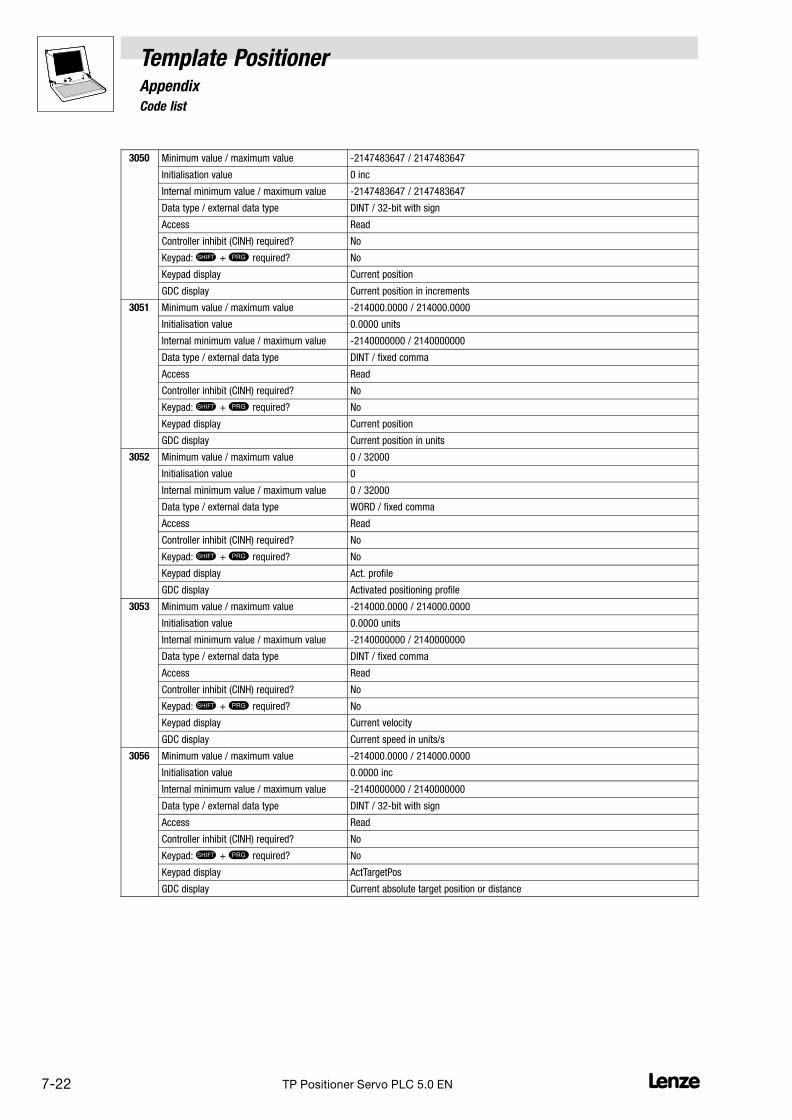
7.5 Code list
Template PositionerAppendix
7−22 LTP Positioner Servo PLC 5.0 EN
3050 Minimum value / maximum value −2147483647 / 2147483647
Initialisation value 0 inc
Internal minimum value / maximum value −2147483647 / 2147483647
Data type / external data type DINT / 32−bit with sign
Access Read
Controller inhibit (CINH) required? No
Keypad: � + required? No
Keypad display Current position
GDC display Current position in increments
3051 Minimum value / maximum value −214000.0000 / 214000.0000
Initialisation value 0.0000 units
Internal minimum value / maximum value −2140000000 / 2140000000
Data type / external data type DINT / fixed comma
Access Read
Controller inhibit (CINH) required? No
Keypad: � + required? No
Keypad display Current position
GDC display Current position in units
3052 Minimum value / maximum value 0 / 32000
Initialisation value 0
Internal minimum value / maximum value 0 / 32000
Data type / external data type WORD / fixed comma
Access Read
Controller inhibit (CINH) required? No
Keypad: � + required? No
Keypad display Act. profile
GDC display Activated positioning profile
3053 Minimum value / maximum value −214000.0000 / 214000.0000
Initialisation value 0.0000 units
Internal minimum value / maximum value −2140000000 / 2140000000
Data type / external data type DINT / fixed comma
Access Read
Controller inhibit (CINH) required? No
Keypad: � + required? No
Keypad display Current velocity
GDC display Current speed in units/s
3056 Minimum value / maximum value −214000.0000 / 214000.0000
Initialisation value 0.0000 inc
Internal minimum value / maximum value −2140000000 / 2140000000
Data type / external data type DINT / 32−bit with sign
Access Read
Controller inhibit (CINH) required? No
Keypad: � + required? No
Keypad display ActTargetPos
GDC display Current absolute target position or distance

Template PositionerAppendix
7.5 Code list
7−23L TP Positioner Servo PLC 5.0 EN
3057 Minimum value / maximum value −214000.0000 / 214000.0000
Initialisation value 0.0000 units
Internal minimum value / maximum value −2140000000 / 2140000000
Data type / external data type DINT / fixed comma
Access Read
Controller inhibit (CINH) required? No
Keypad: � + required? No
Keypad display TargetPosReal
GDC display Target position or distance in units
3060 Minimum value / maximum value 0 / 4294960000
Initialisation value 0 units/s
Internal minimum value / maximum value 0 / 4294960000
Data type / external data type DWORD / 32−bit without sign
Access Read
Controller inhibit (CINH) required? No
Keypad: � + required? No
Keypad display Max for C1240
GDC display Max. speed for C1240
3062 Minimum value / maximum value 0.0000 / 214000.0000
Initialisation value 0.0000 units
Internal minimum value / maximum value 0 / 2140000000
Data type / external data type DINT / fixed comma
Access Read
Controller inhibit (CINH) required? No
Keypad: � + required? No
Keypad display Max. distance
GDC display Max. distance traversed / distance
3063 Minimum value / maximum value 0.0000 / 214000.0000
Initialisation value 0.0000 units/s
Internal minimum value / maximum value 0 / 2140000000
Data type / external data type DINT / fixed comma
Access Read
Controller inhibit (CINH) required? No
Keypad: � + required? No
Keypad display Min velocity
GDC display Min. profile speed in units/s
3065 Minimum value / maximum value 0 / 65535
Initialisation value 0
Internal minimum value / maximum value 0 / 65535
Data type / external data type WORD / fixed comma
Access Write/read
Controller inhibit (CINH) required? No
Keypad: � + required? No
Selection: 0: StandBy
1: Trouble
20: ManualJog
30: Homing
40: Positioning
Keypad display PosState
GDC display Positioning status

7.5 Code list
Template PositionerAppendix
7−24 LTP Positioner Servo PLC 5.0 EN
3066 Minimum value / maximum value 0 / 32767
Initialisation value 0
Internal minimum value / maximum value 0 / 32767
Data type / external data type INT / fixed comma
Access Write/read
Controller inhibit (CINH) required? No
Keypad: � + required? No
Selection: 15700: InvProfPar
15788: ProfAuxVelEq0
15789: ProfAuxDecEq0
15790: ProfAuxAccEq0
15798: ProfVelEq0
15799: ProfDecEq0
15800: ProfAccEq0
16000: NoAction
16001: PosDone
16010: Acceleration
16011: ConstSpeed
16012: Deceleration
16013: Reversing
16100: ResetActive
16101: LoadStartVal
16102: AbortActive
16103: ExtSetVal
16300: NoTPDetected
Keypad display ProfilerState
GDC display Profile generator status
3090 Minimum value / maximum value −2147483647 / 2147483647
Initialisation value 0 units
Internal minimum value / maximum value −2147483647 / 2147483647
Data type / external data type DINT / 32−bit with sign
Array size 10 (Determined via the global variable C_wNumberOfPosCorrectionValues.)
Access Write/read
Controller inhibit (CINH) required? No
Keypad: � + required? No
Keypad display CorrPosition
GDC display Correction position
3091 Minimum value / maximum value −2147483647 / 2147483647
Initialisation value 0 units
Internal minimum value / maximum value −2147483647 / 2147483647
Data type / external data type DINT / 32−bit with sign
Array size 10 (Determined via the global variable C_wNumberOfPosCorrectionValues.)
Access Write/read
Controller inhibit (CINH) required? No
Keypad: � + required? No
Keypad display CorrPosValue
GDC display Position correction value

Template PositionerAppendix
7.5 Code list
7−25L TP Positioner Servo PLC 5.0 EN
3100 Minimum value / maximum value −214000.0000 / 214000.0000
Initialisation value 0.0000 units
Internal minimum value / maximum value −2140000000 / 2140000000
Data type / external data type DINT / fixed comma
Array size 5 (Determined via the global variable C_wNumberOfMotionObjects.)
Access Write/read
Controller inhibit (CINH) required? No
Keypad: � + required? No
Keypad display Prof.Position
GDC display Profile parameter position
3200 Minimum value / maximum value −214000.0000 / 214000.0000
Initialisation value 0.0000 units/s
Internal minimum value / maximum value −2140000000 / 2140000000
Data type / external data type DINT / fixed comma
Array size 5 (Determined via the global variable C_wNumberOfMotionObjects.)
Access Write/read
Controller inhibit (CINH) required? No
Keypad: � + required? No
Keypad display Prof.Velocity
GDC display Profile parameter speed
3300 Minimum value / maximum value 0.0000 / 214000.0000
Initialisation value 0.0000 units/s2
Internal minimum value / maximum value 0 / 2140000000
Data type / external data type DINT / fixed comma
Array size 5 (Determined via the global variable C_wNumberOfMotionObjects.)
Access Write/read
Controller inhibit (CINH) required? No
Keypad: � + required? No
Keypad display Prof.Acc
GDC display Profile parameter acceleration
3400 Minimum value / maximum value 0.0000 / 214000.0000
Initialisation value 0.0000 units/s2
Internal minimum value / maximum value 0 / 2140000000
Data type / external data type DINT / fixed comma
Array size 5 (Determined via the global variable C_wNumberOfMotionObjects.)
Access Write/read
Controller inhibit (CINH) required? No
Keypad: � + required? No
Keypad display Prof.Dec
GDC display Profile parameter deceleration
3500 Minimum value / maximum value −214000.0000 / 214000.0000
Initialisation value 0.0000 units/s
Internal minimum value / maximum value −2140000000 / 2140000000
Data type / external data type DINT / fixed comma
Array size 5 (Determined via the global variable C_wNumberOfMotionObjects.)
External data type / external data type Fixed comma
Access Write/read
Controller inhibit (CINH) required? No
Keypad: � + required? No
Keypad display Prof.FinalVel
GDC display Profile parameter final speed

7.5 Code list
Template PositionerAppendix
7−26 LTP Positioner Servo PLC 5.0 EN
3600 Minimum value / maximum value 0.0000 / 214000.0000
Initialisation value 0.0000 ms
Internal minimum value / maximum value 0 / 2140000000
Data type / external data type DINT / fixed comma
Array size 5 (Determined via the global variable C_wNumberOfMotionObjects.)
Access Write/read
Controller inhibit (CINH) required? No
Keypad: � + required? No
Keypad display Prof.JerkTime
GDC display Profile parameter jerk time
3998 Minimum value / maximum value 0 / 65535
Initialisation value 0
Internal minimum value / maximum value 0 / 65535
Data type / external data type WORD / fixed comma
Access Write/read
Controller inhibit (CINH) required? No
Keypad: � + required? No
Selection: All error messages
Keypad display Act. Failure
GDC display Current PLC or template error
3999 Minimum value / maximum value 0 / 4294967295
Initialisation value 0
Internal minimum value / maximum value 0 / 4294967295
Data type / external data type DWORD / fixed comma
Access Read
Controller inhibit (CINH) required? No
Keypad: � + required? No
Keypad display Templ.Version
GDC display Version of the template

Template PositionerAppendix
7.6 Visualisation
7−27L TP Positioner Servo PLC 5.0 EN
7.6 Visualisation
All visualisations used in the Lenze templates have the same structure:
L
�
� �
�
�
Fig. 7−1 Basic structure of the visualisation used in the template
� Menu You can select the desired template function from the menu. After selection, the function is visualised inthe dialog area.� Dialog area
� Control fields Area for cross−function control fields (buttons).
Important:
The "software switches" QSP and CINH only trigger quick stop or controller inhibit when onlineconnected to the PLC. They therefore do not fulfill the safety requirements for EMERGENCY STOPdevices which have to be effective in all operating states of the plant or system.
� Current values Area in which the current parameter values of the template are displayed.
� Status messages Area in which cross−function status messages from the PLC or the template are displayed.
Tip!
You can obtain additional information on a visualisation object by positioning the mouse pointer overthe object until a "tool tip" is displayed:

7.6 Visualisation
Template PositionerAppendix
7−28 LTP Positioner Servo PLC 5.0 EN

Template PositionerIndex
8−1l TP Positioner Servo PLC 5.0 EN
8 IndexA
Absolute position, 2−2
Absolute positioning, 5−31
Acceleration, 2−1 , 2−3
Acceleration override, 5−61
C
Change, profile parameters, 5−71
Changeover, 2−6
Changeover to external setpoints, 5−8
Changing profile parameters, during positioning, 5−61
Code list, 7−15
Command interface"MoveAxis", 5−43
Commissioning, 4−1
Preconditions, 4−1
Principles, 4−1
constant approach, 5−31
Constants, 7−9
D
Deceleration, 2−1 , 2−3
Definition of the dwell time, 5−34
Digital inputs, Limit switch/reference switch assignment,5−17
E
Easy transfer of profile parameters, 5−43
Enumeration data type, 7−12
Error messages, 7−13
ErrorCode (ENUM), 7−13
External setpoints, 5−7
F
Feed constant, 2−7
Feed correction, 5−73
Memory requirements, 7−1
Feedback system, 2−7
Final speed, 2−1
Following errors, 5−82
Following error limit, 5−82
Following error warning limit, 5−82
Function "MoveAxis" , 5−43
Functions/function modules
ChangeProfile, 5−71
ExternalSetValuePositioning, 5−7
Homing, 5−14
ManualJog, 5−22
OverchangePositioning, 5−53
OverridePositioning, 5−61
PositionCorrection, 5−73
PositionTeach, 5−9
StandardPositioning, 5−35
StaticHomePositionSet, 5−10
TemplateControl, 5−78
TouchProbePositioning, 5−44
G
Gearbox factor of the encoder system, 2−7
Gearbox ratio, 2−7
Global variable, 7−2
H
Hardware limit positions, 2−6 , 5−84
Home position
Checking whether known, 5−30
delete, 5−12
setting, 5−12
Status, 5−12
Homing, 2−4 , 5−13 , 5−14
with a band drive (example), 5−20
with a leadscrew drive (example), 5−19
I
Input variables, reserved, 7−11
J
Jerk, 2−1
Jerk limitation, 2−3 , 5−34
Jog control, 5−22
L
L_FWM, 6−1
Limit positions, 2−6
Limit switch
Assignment of digital inputs, 5−17
Using the limit switch as a home switch, 5−17
Limit switches, 5−84
Retracting from limit switches, 5−26

Template PositionerIndex
8−2 lTP Positioner Servo PLC 5.0 EN
M
Machine parameters, 2−7
Manual homing, 2−4 , 5−22
Quick stop, 5−24
Soft start, 5−24
to hardware limit positions, 5−26
to software limit positions, 5−25
Maximum acceleration, 2−8
Maximum jerk, 2−8
Maximum speed, 2−7
Measured−value table, 5−74
Memory, 7−1
Message window"#Target position reached" Definition, 5−33
Modulo positioning, 5−31
Motor type, 2−7
MoveAxis function, 5−43
O
Offset, Entries for the selection of the zero position, 5−18
Overchange, 5−53 , 5−57
Overchange (changeover), 2−6
Override, 2−5 , 5−61 , 5−65
P
Parallel processes, 5−77
Parameter monitor, 5−30 , 5−75
Position, 2−1 , 2−2
Positioning
Cancel, 5−32
General information, 5−28
Override, 5−61
touch probe (remaining path), 5−44
positioning, Overchange, 5−53
Positioning , Start, 5−32
Positioning modes, 5−31
Positioning sequencer, 6−3
Principle, 6−4
Profile, 2−1
Profile change during positioning (override), 2−5
Profile generator (L_MCProfileGenerator), Profile generatormodes, 5−38
Profile linkage with overchange, 5−57
Profile names, 5−29 , 7−12
change, 5−30
Profile parameters, 2−1 , 5−29
Entry, 5−30
ProfileNames (ENUM), 7−12
Profiles, Selection of the number, 5−29 , 7−12
Q
Quick stop of drive, 5−81
R
Reference switch, 5−17
Relative position, 2−2
Relative positioning, 5−31
Remaining path positioning, 5−44 , 5−49
Modes, 5−50
Remaining path positioning (touch probe), 2−5
Reserved input variables, 7−11
Retracting from limit switches, 5−26
S
S−profiles, 2−3 , 5−34
Safety information, Layout
Other notes, 1−1
Warning of material damage, 1−1
Saving of the actual position, 5−9
Selection of the zero position, 5−18
Sequential function chart, 4−3
General information, 4−2
Setting a home position, 2−4
Setting of home positions, 5−13
Setting of the home position, 5−10
Settings, 7−12
Software architecture, 3−2
Software limit positions, 2−6 , 5−83
Positioning to software limit positions, 5−25
Speed, 2−1 , 2−2
Speed mode, 5−31
Speed override, 5−61
Standard positioning, 5−35
Status
PosFunctions (parallel processes), 5−77
StandBy, 5−6
Status changes (transitions), 5−4
Status machine, 5−1

Template PositionerIndex
8−3l TP Positioner Servo PLC 5.0 EN
Statuses
Homing, 5−13
Positioning, 5−27
Short description, 5−2
Sub−codes for profile parameters, 5−29
Supported functions, 1−3
T
Target interface, input variables, 7−11
Task run times, 7−1
Teach in, 5−9
Technical data, 7−1
Template, 3−1
applications, 3−1
Constants, 7−9
Settings, 5−78 , 7−9
Template error messages, 7−13
Term definitions, 1−2
Terminology used, 2−1
Touch probe, 2−5 , 5−44
Positioning modes, 5−31
Touch probe evaluation, 5−49
Transitions, 5−4
Troubleshooting, 6−1
U
unit, 1−2
User error messages, 7−14
User quick stop), 5−81
User−defined interface for touch probe, 5−49
UserDataTypes, 7−12
UserErrors (PRG), 6−1
UserInterface (PRG), 6−3
UserQuickstop, 5−81
V
Variables, reserved input variables, 7−11
Version info, 1−2
Z
Zero position, 2−4 , 5−18
zero position, 5−13


