Mounting Connection Operation - Caleffi · The iSolar WMZ is a universal calorimeter for thermal...
16
iSolar WMZ Thank you for buying this product. Read this manual carefully to get the best perfomance from this unit Mounting Connection Operation Manual *11205035* 11205035 en-US/CA
Transcript of Mounting Connection Operation - Caleffi · The iSolar WMZ is a universal calorimeter for thermal...

iSol
ar W
MZ
Thank you for buying this product.Read this manual carefully to get the best perfomance from this unit
MountingConnectionOperation
Manual
*11205035*
1120
5035
en-US/CA

© C
alef
fi_20
1309
25_i
Sola
r_W
MZ
.mon
us.in
dd
| 2
Table of contents
Safety advice ............................................................ 2Technical data .......................................................... 3
1. Installation .......................................................... 51.1 Mounting .................................................................... 51.2 Electrical connection ............................................... 51.3 Flowmeter .................................................................. 5
2. Operation and function ..................................... 62.1 Push buttons for adjustment ................................. 62.2 Graphic display .......................................................... 62.3 LED flashing codes ................................................... 6
3. Determining the ratio of the glycol-water mixture ............................................................................... 7
4. Commissioning ................................................... 7
5. Function .............................................................. 9
6. Indication and adjustment channels ................ 96.1 Heat quantity ........................................................... 106.2 Flow and return temperatures ............................ 106.3 Volumetric flow rate.............................................. 106.4 Power ........................................................................ 106.5 Reset balance .......................................................... 10
6.6 Antifreeze type ....................................................... 106.7 Antifreeze................................................................. 106.8 Type of flowmeter .................................................. 116.9 Impulse rate ............................................................. 116.10 Subaddress ............................................................... 116.11 Bus mode ................................................................. 116.12 Bus master ............................................................... 116.13 Sensor offset............................................................ 126.14 Language ................................................................... 126.15 Temp. unit ................................................................. 126.16 Flow unit .................................................................. 126.17 Energy unit ............................................................... 126.18 Reset ......................................................................... 126.19 Version ...................................................................... 12
7. Examples of connection .................................. 137.1 iSolar WMZ module in individual operation
mode .......................................................................... 137.2 iSolar WMZ with controller ................................ 137.3 Cascade without controller ................................. 137.4 Cascade with controller ....................................... 13
8. Troubleshooting ............................................... 14
Safety advice:Please read the following information carefully before in-stalling and operating the controller. In this way damage to the solar system caused by wrong installation will be avoid-ed. Please make sure that the mounting is adapted to the characteristics of the building, that the local regulations are respected and is conform with the technical rules.Please pay attention to the following safety advice in order to avoid danger and damage to people and property.
Description of symbols
Signal words describe the danger that may occur, when it is not avoided.
WaRnIng means that injury, possibly life-threatening injury, can occur.aTTEnTIOn means that damage to the appliance can occur.
Information about the product
Proper usageThe iSolar WMZ is to be used for the measurement and the display of heat quantity and other system data in compliance with the technical data specified in this manual. Improper use excludes all liability claims.
noteStrong electromagnetic fields can impair the function of the controller.
Î Make sure the controller as well as the system are not exposed to strong electro-magnetic fields.
Instructions:Attention should be paid to• Valid national and local standards and regulations• Respective valid standards and directivesEquipment to be installed and used in accordance with the rules of the National Electrical Code (NEC) or with Cana-dian Electrical Code (CEC), Part I.These instructions are exclusively addressed to authorized skilled personnel. • Only qualified electricians should carry out installation
and maintenance work.• Initial installation should be carried out by qualified per-
sonnel
Î Arrows indicate instruction steps that should be carried out.
general
Warnings are indicated with a warning triangle! They contain information on how to avoid the danger described.
© C
alef
fi_20
1309
25_i
Sola
r_W
MZ
.mon
us.in
dd
3 |
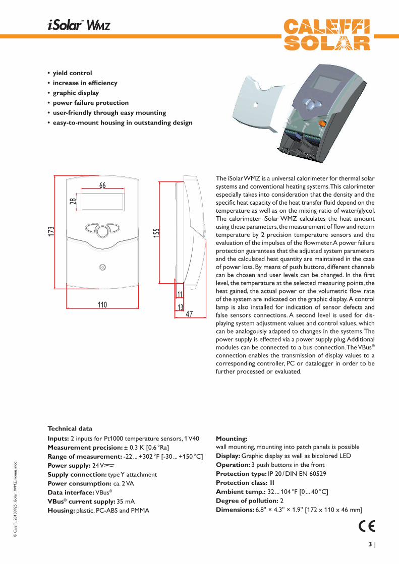
• yield control
• increase in efficiency
• graphic display
• power failure protection
• user-friendly through easy mounting
• easy-to-mount housing in outstanding design
Technical data
Inputs: 2 inputs for Pt1000 temperature sensors, 1 V40Measurement precision: ± 0.3 K [0.6 °Ra]Range of measurement: -22 ... +302 °F [-30 ... +150 °C]Power supply: 24 V
S11 2 3 4 5 6 9 10 12 13 14
Netz / Mains
T0,8A
IP 20
2019S2 V40 VBus N L
CALEFFINORTH AMERICA, Inc.Milwaukee, WI 53208
Supply connection: type Y attachmentPower consumption: ca. 2 VAData interface: VBus®
VBus® current supply: 35 mAHousing: plastic, PC-ABS and PMMA
The iSolar WMZ is a universal calorimeter for thermal solar systems and conventional heating systems. This calorimeter especially takes into consideration that the density and the specific heat capacity of the heat transfer fluid depend on the temperature as well as on the mixing ratio of water/glycol. The calorimeter iSolar WMZ calculates the heat amount using these parameters, the measurement of flow and return temperature by 2 precision temperature sensors and the evaluation of the impulses of the flowmeter. A power failure protection guarantees that the adjusted system parameters and the calculated heat quantity are maintained in the case of power loss. By means of push buttons, different channels can be chosen and user levels can be changed. In the first level, the temperature at the selected measuring points, the heat gained, the actual power or the volumetric flow rate of the system are indicated on the graphic display. A control lamp is also installed for indication of sensor defects and false sensors connections. A second level is used for dis-playing system adjustment values and control values, which can be analogously adapted to changes in the systems. The power supply is effected via a power supply plug. Additional modules can be connected to a bus connection. The VBus® connection enables the transmission of display values to a corresponding controller, PC or datalogger in order to be further processed or evaluated.
Mounting: wall mounting, mounting into patch panels is possibleDisplay: Graphic display as well as bicolored LEDOperation: 3 push buttons in the frontProtection type: IP 20 / DIN EN 60529Protection class: IIIambient temp.: 32 ... 104 °F [0 ... 40 °C]Degree of pollution: 2Dimensions: 6.8'' × 4.3'' × 1.9'' [172 x 110 x 46 mm]
© C
alef
fi_20
1309
25_i
Sola
r_W
MZ
.mon
us.in
dd
| 4
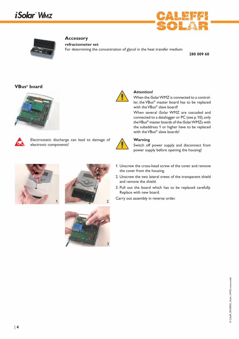
accessoryrefractometer setFor determining the concentration of glycol in the heat transfer medium 280 009 60
1. Unscrew the cross-head screw of the cover and re move the cover from the housing.
2. Unscrew the two lateral srews of the transparent shield and remove the shield.
3. Pull out the board which has to be replaced carefully.Replace with new board.
Carry out assembly in reverse order.
attention!When the iSolar WMZ is connected to a control-ler, the VBus® master board has to be replaced with the VBus® slave board!When several iSolar WMZ are cascaded and connected to a datalogger or PC (see p. 10), only the VBus® master boards of the iSolar WMZs with the subaddress 1 or higher have to be replaced with the VBus® slave boards!
WarningSwitch off power supply and disconnect from power supply before opening the housing!
VBus® board
1 2
3
Electrostatic discharge can lead to damage of electronic components!
© C
alef
fi_20
1309
25_i
Sola
r_W
MZ
.mon
us.in
dd
5 |
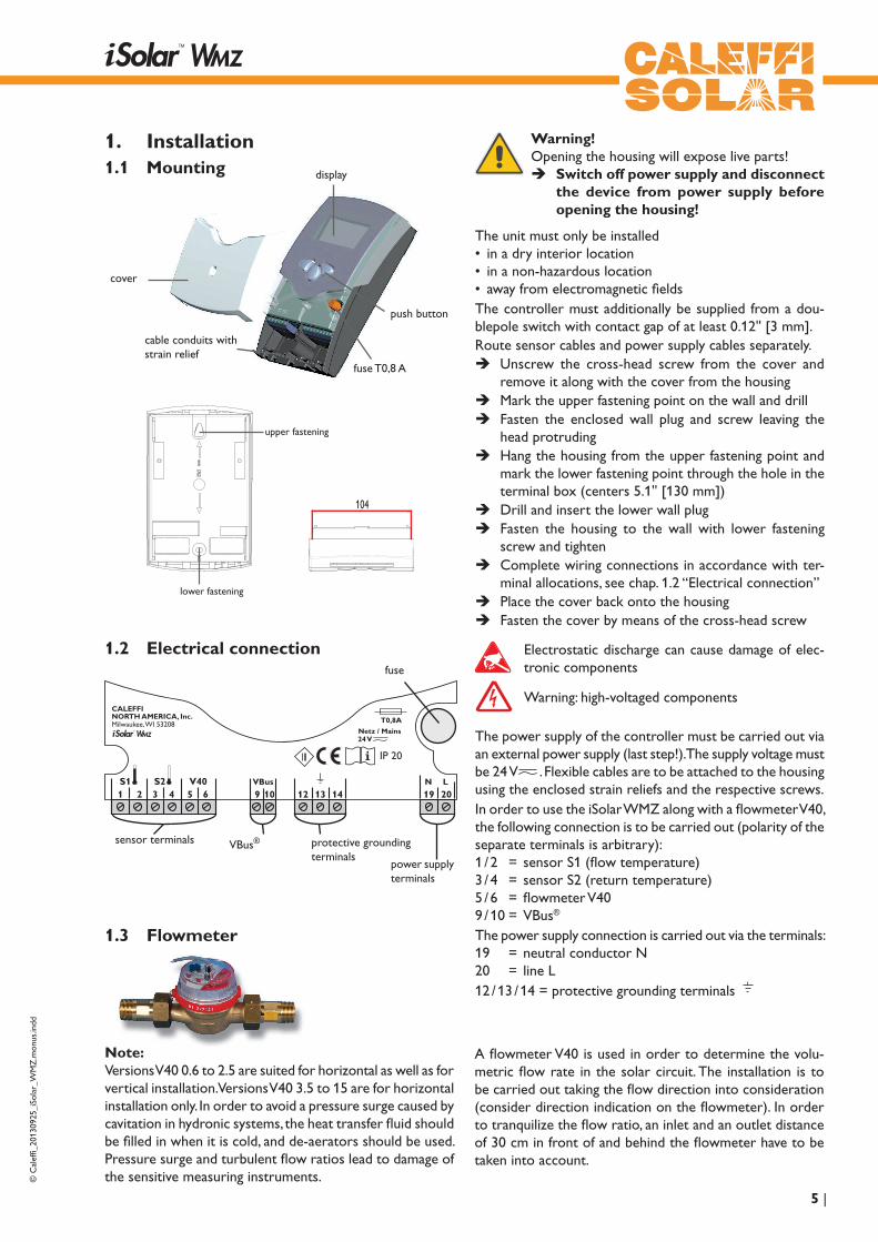
protective grounding terminals
S11 2 3 4 5 6 9 10 12 13 14
Netz / Mains
T0,8A
IP 20
2019S2 V40 VBus N L
CALEFFINORTH AMERICA, Inc.Milwaukee, WI 53208
power supply terminals
sensor terminals VBus®
display
push button
fuse T0,8 A
cable conduits with strain relief
cover
1. Installation1.1 Mounting
Warning!Opening the housing will expose live parts!
Î Switch off power supply and disconnect the device from power supply before opening the housing!
1.2 Electrical connection
The power supply of the controller must be carried out via an external power supply (last step!). The supply voltage must be 24 V
S11 2 3 4 5 6 9 10 12 13 14
Netz / Mains
T0,8A
IP 20
2019S2 V40 VBus N L
CALEFFINORTH AMERICA, Inc.Milwaukee, WI 53208
. Flexible cables are to be attached to the housing using the enclosed strain reliefs and the respective screws.In order to use the iSolar WMZ along with a flowmeter V40, the following connection is to be carried out (polarity of the separate terminals is arbitrary):1 / 2 = sensor S1 (flow temperature)3 / 4 = sensor S2 (return temperature)5 / 6 = flowmeter V409 / 10 = VBus®
The power supply connection is carried out via the terminals:19 = neutral conductor N20 = line L12 / 13 / 14 = protective grounding terminals
fuse
upper fastening
lower fastening
Electrostatic discharge can cause damage of elec-tronic components
Warning: high-voltaged components
The unit must only be installed• in a dry interior location• in a non-hazardous location• away from electromagnetic fieldsThe controller must additionally be supplied from a dou-blepole switch with contact gap of at least 0.12'' [3 mm].Route sensor cables and power supply cables separately.
Î Unscrew the cross-head screw from the cover and remove it along with the cover from the housing
Î Mark the upper fastening point on the wall and drill Î Fasten the enclosed wall plug and screw leaving the
head protruding Î Hang the housing from the upper fastening point and
mark the lower fastening point through the hole in the terminal box (centers 5.1'' [130 mm])
Î Drill and insert the lower wall plug Î Fasten the housing to the wall with lower fastening
screw and tighten Î Complete wiring connections in accordance with ter-
minal allocations, see chap. 1.2 “Electrical connection” Î Place the cover back onto the housing Î Fasten the cover by means of the cross-head screw
A flowmeter V40 is used in order to determine the volu-metric flow rate in the solar circuit. The installation is to be carried out taking the flow direction into consideration (consider direction indication on the flowmeter). In order to tranquilize the flow ratio, an inlet and an outlet distance of 30 cm in front of and behind the flowmeter have to be taken into account.
1.3 Flowmeter
note: Versions V40 0.6 to 2.5 are suited for horizontal as well as for vertical installation. Versions V40 3.5 to 15 are for horizontal installation only. In order to avoid a pressure surge caused by cavitation in hydronic systems, the heat transfer fluid should be filled in when it is cold, and de-aerators should be used. Pressure surge and turbulent flow ratios lead to damage of the sensitive measuring instruments.

© C
alef
fi_20
1309
25_i
Sola
r_W
MZ
.mon
us.in
dd
| 6
132
backward (-) forward (+)
OK(selection / adjustment)
The iSolar WMZ is operated by 3 push buttons below the display. The forward-key (1) is used for scrolling forward through the indication menu or to increase the adjustment values. The backward-key (2) is used for scrolling backwards through the menu or to decrease adjustment values.In order to change from the display level to the adjustment level, briefly press button 3. The indication changes to the adjustment mode.
Î Select channel with buttons 1 and 2
Î Briefly press button 3.
Î Adjust value with the buttons 1 and 2
Î Briefly press button 3. Answer the safety prompt “Save ?“ with “yes“ oder “no“ (select with buttons 1 and 2) and confirm with button 3.
In order to get back to the display level, select the item “back“, and briefly press button 2.
Safety prompt: Save? Yes
Adjust. values: back Reset balance Antifr. type Water
2. Operation and function2.1 Push buttons for adjustment
The iSolar WMZ has two display levels. In the 1st level, the heat quantity as well as flow and return temperatures are shown. Furthermore, it contains a system screen.
System screen: in the system screen, the system scheme and the sensors used are shown.The 2nd level is the adjustment level in which various pa-rameters and values can be adjusted.
FL
RE
15 kWh Heat
85,6 °C 45,7 °C
constant green: everything OKflashing red: sensor fault
2.2 graphic display
2.3 LED flashing codes

© C
alef
fi_20
1309
25_i
Sola
r_W
MZ
.mon
us.in
dd
7 |
Since the heat capacity of the heat transfer fluid depends on the concentration of glycol, the proportion of the glycol/water-mixture has to be determined first.Determining the ratio for known volumes:If the volumes of water and glycol in the system are known, the value in vol. % is calculated as follows:Vol % = (Vg : (VW + Vg)) x 100VG: volume of glycolVW: volume of waterExample:if 15 liters of water and 20 liters of glycol are used in the solar circuit, then follows:Vol % = (20 : (15 + 20)) x 100 = 57
Determining the ratio for unknown volumes:
refractomter:In order to analyze the system, a small amount of fluid has to be withdrawn from the solar circuit and applied to the prism surface of the refractometer. Hold the pointy end against the light and turn the ocular until the borderlines become visible. The borderlines indicate the freezing temperature. In a table on the receptacle of the heat transfer fluid, the value for the vol.-% corresponding to the temperature value, is shown.
3. Determining the ratio of the glycol-water mixture (when using ready mixed fluids, pay attention to manufacturers‘ instructions)
Commissioning: Version x.xx Language English Temp. unit °C
4. CommissioningWhen the iSolar WMZ calorimeter is commissioned for the first time or after a reset, it will run a commissioning menu. The commissioning menu leads the user through the most important adjustment channels needed.
Commissioning menuThe commissioning menu consists of the channels described in the following.At the top of the commissioning menu, the version number of the device is indicated.
Commissioning: Language English Temp. unit °C Flow unit Litres/hour
LanguageSelection: Deutsch, English, Francais, Italiano, EspanolFactory setting: Deutsch
Î Adjust the desired menu language.
Commissioning: Temp. unit °C Flow unit Litres/hour Energy unit kWh
Temp. unitSelection: °C, °FFactory setting:°C
Î Adjust the desired temeprature unit.

© C
alef
fi_20
1309
25_i
Sola
r_W
MZ
.mon
us.in
dd
| 8
Commissioning: Flow unit Litres/hour Energy unit kWh Antifr. type Water
Flow unitSelection: Litres/hour, Gal./minuteFactory setting: Litres/hour
Î Adjust the desired flow rate unit.
Completing the commissioning menu:When the last menu item of the commissioning menu (Save) has been selected, a security inquiry appears. If the inquiry is confirmed, the adjustments will be saved. All adjustments made during commissioning can, if necessary, be changed later on in the corresponding menus.
Commissioning: Energy unit kWh Antifr. type Water Antifreeze 40 %
Energy unitSelection: kWh, BTUFactory setting: kWh
Î Adjust the desired energy unit.
Commissioning: Energy unit kWh Antifr. type Water Antifreeze 40 %
antifr. typeSelection: Water, Propylene, Ethylene, Tyfo LSFactory setting: Water
Î Adjust the heat transfer fluid used in the system.
Commissioning: Antifr. type Propylene Antifreeze 40 % Volume/Imp. 1.0 L/I
Commissioning: Antifreeze 40 % Volume/Imp. 1.0 L/I Save
Volume/Imp.Adjustment range: 0.1 ... 99.9 L/IFactory setting: 1.0 L/I
Î Adjust the impulse rate of the flowmeter or flow rate sensor respectively.
Commissioning: Antifr. type Propylene Antifreeze 40 % Volume/Imp. 1.0 L/I
antifreezeAdjustment range: 20 ... 70 %Factory setting: 40 %Available only if Antifr. type is set to Propylene or Ethylene.
Î Adjust the antifreeze ratio of the heat transfer fluid used in the system.
© C
alef
fi_20
1309
25_i
Sola
r_W
MZ
.mon
us.in
dd
9 |
During the calculation of the transferred heat quantity, the calorimeter iSolar WMZ takes into account that the specific heat capacity c and the density r depend on the temperature and the mixing proportion (access to limited values). Using these parameters, the measurement of the flow and return temperatures with two precision temperature sensors, and the evaluation of the impulses of a volumetric flowmeter, the iSolar WMZ calculates the transferred quantity.
This device can be used in systems which use water or wa-ter-propylene glycol mixtures as the heat transfer fluid. The proportion (in vol%) used in a system and the specification of the selected flowmeter (in liters per impulse) are adjusted locally after the installation.
5. Function
6. Indication and adjustment channelsDisplay channels• FL (flow temperature in °C / °F)• RE (return temperature in °C / °F)• heat quantity
(in Wh / MBTU or kWh / MMBTU respectively)• volumetric flow rate (in l/min or gpm)• power (in kW)
adjustment channels• antifreeze type• antifreeze• flow measurement (V40 or VTP)• volume per impulse • subaddress• bus mode• bus master• sensor offset• language• temperature unit• flow rate unit• energy unit
Safety prompt: Save? Yes
note:After a change in the adjustment channel has been made, a safety prompt appears. The adjustment is saved after the question has been confirmed with “yes“.
FL
RE
15 kWh Heat
85,6 °C 45,7 °C
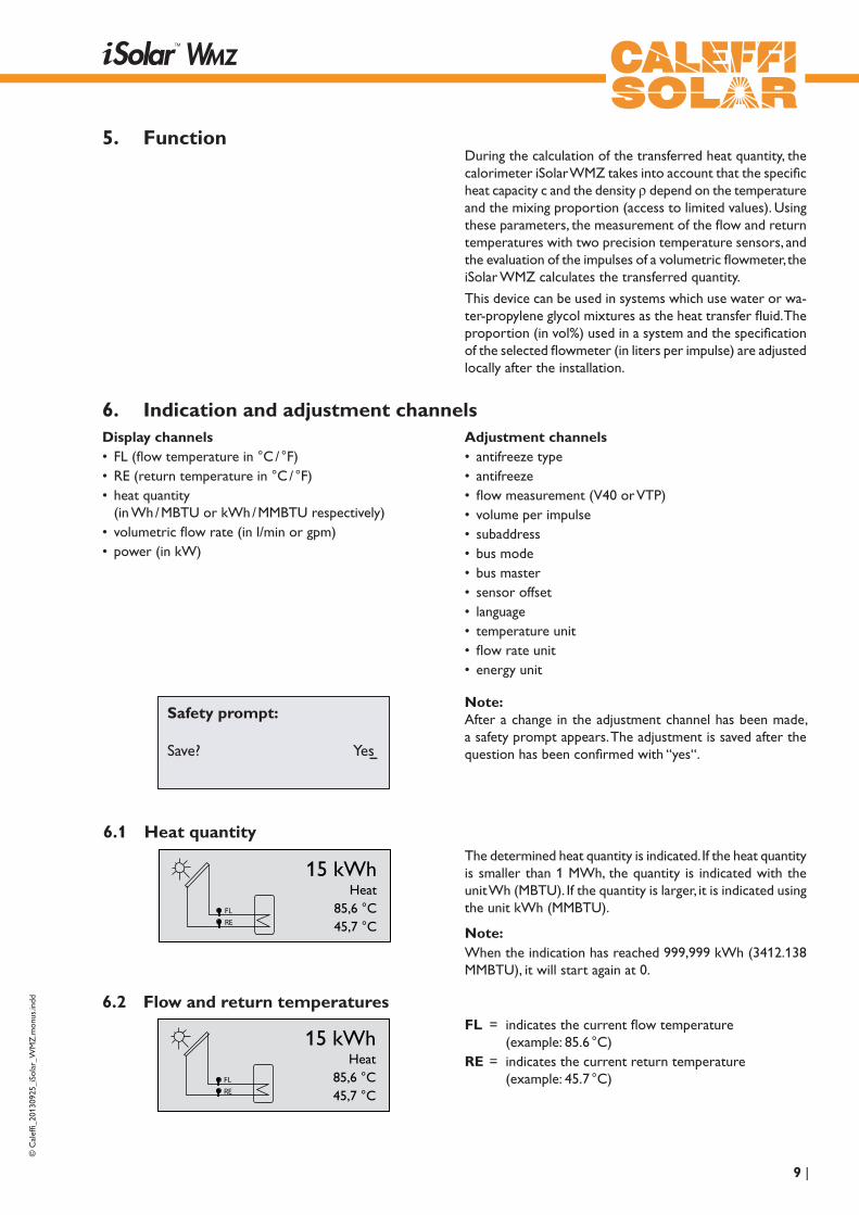
6.1 Heat quantity
FL
RE
15 kWh Heat
85,6 °C 45,7 °C
6.2 Flow and return temperaturesFL = indicates the current flow temperature (example: 85.6 °C)RE = indicates the current return temperature (example: 45.7 °C)
The determined heat quantity is indicated. If the heat quantity is smaller than 1 MWh, the quantity is indicated with the unit Wh (MBTU). If the quantity is larger, it is indicated using the unit kWh (MMBTU).
note:When the indication has reached 999,999 kWh (3412.138 MMBTU), it will start again at 0.
© C
alef
fi_20
1309
25_i
Sola
r_W
MZ
.mon
us.in
dd
| 10
FL
RE
200 l/hFlow
85,6 °C45,7 °C
FL
RE
9.30 kWPower
85,6 °C45,7 °C
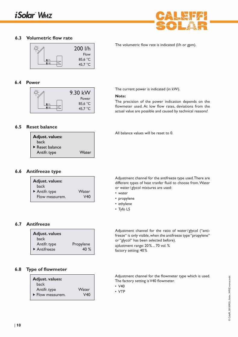
The volumetric flow rate is indicated (l/h or gpm).
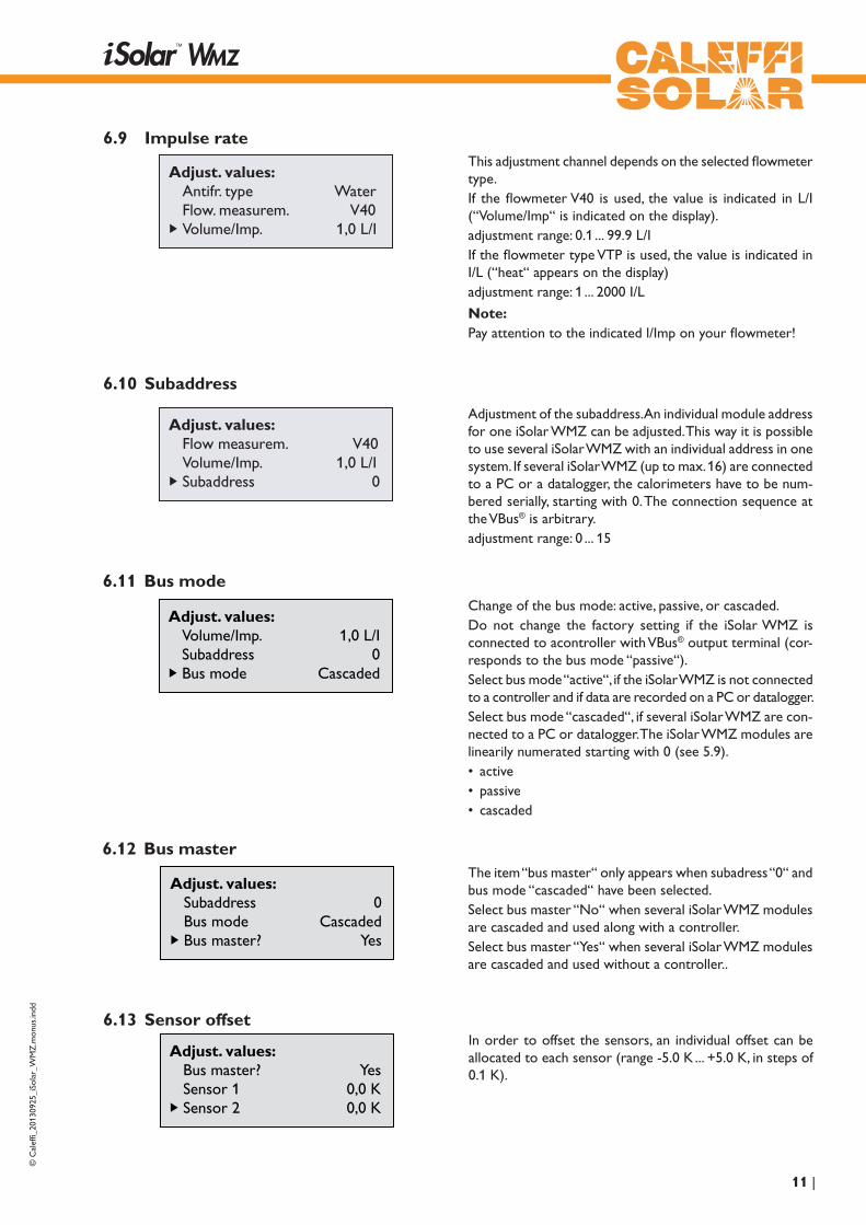
The current power is indicated (in kW).
note:The precision of the power indication depends on the flowmeter used. At low flow rates, deviations from the actual value are possible and caused by technical reasons!
6.3 Volumetric flow rate
6.4 Power
All balance values will be reset to 0.
6.5 Reset balance
Adjust. values: back Reset balance Antifr. type Water
Adjust. values: back Antifr. type Water Flow measurem. V40
Adjustment channel for the antifreeze type used. There are different types of heat tranfer fluid to choose from. Water or water / glycol mixtures are used:• water• propylene• ethylene• Tyfo LS
Adjust. values back Antifr. type Propylene Antifreeze 40 %
Adjustment channel for the ratio of water / glycol (“anti-freeze“ is only visible, when the antifreeze type “propylene“ or “glycol“ has been selected before).ajdustment range: 20 % ... 70 vol. % factory setting: 40 %
Adjust. values: back Antifr. type Water Flow measurem. V40
Adjustment channel for the flowmeter type which is used. The factory setting is V40 flowmeter.• V40• VTP
6.6 antifreeze type
6.7 antifreeze
6.8 Type of flowmeter
© C
alef
fi_20
1309
25_i
Sola
r_W
MZ
.mon
us.in
dd
11 |
Adjust. values: Antifr. type Water Flow. measurem. V40 Volume/Imp. 1,0 L/I
This adjustment channel depends on the selected flowmeter type.If the flowmeter V40 is used, the value is indicated in L/I (“Volume/Imp“ is indicated on the display).adjustment range: 0.1 ... 99.9 L/IIf the flowmeter type VTP is used, the value is indicated in I/L (“heat“ appears on the display)adjustment range: 1 ... 2000 I/L
note:Pay attention to the indicated l/Imp on your flowmeter!
Adjust. values: Flow measurem. V40 Volume/Imp. 1,0 L/I Subaddress 0
Adjustment of the subaddress. An individual module address for one iSolar WMZ can be adjusted. This way it is possible to use several iSolar WMZ with an individual address in one system. If several iSolar WMZ (up to max. 16) are connected to a PC or a datalogger, the calorimeters have to be num-bered serially, starting with 0. The connection sequence at the VBus® is arbitrary.adjustment range: 0 ... 15
6.9 Impulse rate
6.10 Subaddress
Adjust. values: Volume/Imp. 1,0 L/I Subaddress 0 Bus mode Cascaded
6.11 Bus modeChange of the bus mode: active, passive, or cascaded.Do not change the factory setting if the iSolar WMZ is connected to acontroller with VBus® output terminal (cor-responds to the bus mode “passive“). Select bus mode “active“, if the iSolar WMZ is not connected to a controller and if data are recorded on a PC or datalogger.Select bus mode “cascaded“, if several iSolar WMZ are con-nected to a PC or datalogger. The iSolar WMZ modules are linearily numerated starting with 0 (see 5.9).• active• passive• cascaded
The item “bus master“ only appears when subadress “0“ and bus mode “cascaded“ have been selected.Select bus master “No“ when several iSolar WMZ modules are cascaded and used along with a controller.Select bus master “Yes“ when several iSolar WMZ modules are cascaded and used without a controller..
6.12 Bus master
Adjust. values: Subaddress 0 Bus mode Cascaded Bus master? Yes
In order to offset the sensors, an individual offset can be allocated to each sensor (range -5.0 K ... +5.0 K, in steps of 0.1 K).
6.13 Sensor offset
Adjust. values: Bus master? Yes Sensor 1 0,0 K Sensor 2 0,0 K

© C
alef
fi_20
1309
25_i
Sola
r_W
MZ
.mon
us.in
dd
| 12
Adjust. values: Bus mode Cascaded Language English Temp. unit °C
Selection of the language • Deutsch• English• Francais• Italiano• Espanol
6.14 Language
Adjust. values: Language English Temp. unit °C Flow unit Litres/hour
6.15 Temp. unitSelection of the temperature unit for display indication (°C or °F).
Adjust. values: Energy unit kWh Reset Version x.xx
Adjust. values: Energy unit kWh Reset Version x.xx
A reset will delete all previously made adjustments and set all balance values back to 0. The device starts up again with the commissioning menu.
Below the last menu item, the version number of the device is indicated.
Selection of the flow rate unit for display indication (Litres /hour or Gal. / minute).
Selection of the energy unit for display indication (kWh or BTU).
6.16 Flow unit
6.17 Energy unit
Adjust. values: Temp. unit °C Flow unit Litres/hour Energy unit kWh
Adjust. values: Flow unit Litres/hour Energy unit kWh Reset
6.18 Reset
6.19 Version
© C
alef
fi_20
1309
25_i
Sola
r_W
MZ
.mon
us.in
dd
13 |
7. Examples of connection
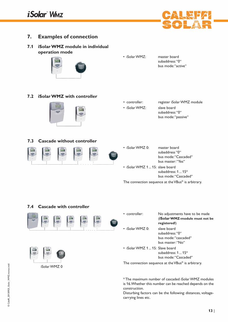
• iSolar WMZ: master board subaddress: “0“ bus mode: “active“
7.1 iSolar WMZ module in individual operation mode
7.2 iSolar WMZ with controller• controller: register iSolar WMZ module
• iSolar WMZ: slave board subaddress: “0“ bus mode: “passive“
7.3 Cascade without controller• iSolar WMZ 0: master board
subaddress “0“ bus mode: “Cascaded“ bus master: “Yes“
• iSolar WMZ 1 ... 15: slave board subaddress: 1 ... 15* bus mode: “Cascaded“
The connection sequence at the VBus® is arbitrary.
7.4 Cascade with controller
• controller: No adjustments have to be made (iSolar WMZ-module must not be registered!)
• iSolar WMZ 0: slave board subaddress: “0“ bus mode: “cascaded“ bus master: “No“
• iSolar WMZ 1 ... 15: Slave board subaddress: 1 ... 15* bus mode: “Cascaded“
The connection sequence at the VBus® is arbitrary.
* The maximum number of cascaded iSolar WMZ modules is 16. Whether this number can be reached depends on the construction.Disturbing factors can be the following: distances, voltage- carrying lines etc.
iSolar WMZ 0

© C
alef
fi_20
1309
25_i
Sola
r_W
MZ
.mon
us.in
dd
| 14
S11 2 3 4 5 6 9 10 12 13 14
Netz / Mains
T0,8A
IP 20
2019S2 V40 VBus N L
CALEFFINORTH AMERICA, Inc.Milwaukee, WI 53208
8. Troubleshooting
Operating control lamp flashes red.
Sensor defect. An error code instead of a temperature is shown in the correspond-ing sensor indication channel.
- 88.8888.8
Line is broken. Check the line.
Short circuit. Check the line.
Pt1000 temperature sensors branched off can be checked with an ohmmeter. In the table shown below, the resistance values corresponding to different temperatures are listed.
Please pay attention to the following items, if the calorimeter iSolar WMZ is not working properly.
fuse T0,8A
°C °F Ω °C °F Ω-10 14 961 55 131 1213-5 23 980 60 140 12320 32 1000 65 149 12525 41 1019 70 158 127110 50 1039 75 167 129015 59 1058 80 176 130920 68 1078 85 185 132825 77 1097 90 194 134730 86 1117 95 203 136635 95 1136 100 212 138540 104 1155 105 221 140445 113 1175 110 230 142350 122 1194 115 239 1442
Resistance values of the Pt1000-sensors
Operating control lamp off.
Check the power supply. Is it disconnected?
no yes
The fuse of the device could be blown. It can be replaced after the front cover has been removed (spare fuse is enclosed in the accessory bag).
Check the supply line and reconnect it.

© C
alef
fi_20
1309
25_i
Sola
r_W
MZ
.mon
us.in
dd
15 |
notes

© C
alef
fi_20
1309
25_i
Sola
r_W
MZ
.mon
us.in
dd
| 16
Distributed by:
© all contents of this document are protected by copyright.
CaLEFFI nORTH aMERICa, Inc.
3883 W. Milwaukee Rd. Milwaukee, WI 53208
Tel.: +1 414.238.2360 Fax: +1 414.238.2366
www.caleffi.us [email protected]