Mounting and Operating Instructions Servo Worm Gear Unit ZM/S
23
® Mounting and Operating Instructions Servo Worm Gear Unit ZM/S Date December 29th 2020 Current on the internet at www.maedler.de Responsible MÄDLER ® branches according to German Post Code Areas: For Switzerland: PCA 1, 2 and 3 PCA 0, 4 und 5 PCA 6, 7, 8 und 9 MÄDLER Norm-Antrieb AG Subsidiary Subsidiary Headquarter Postbox 74 MÄDLER GmbH MÄDLER GmbH MÄDLER GmbH Güterstr. 6 Brookstieg 16 Bublitzer Str. 21 Tränkestr. 6-8 CH-8245 Feuerthalen D-22145 Stapelfeld D-40599 Düsseldorf D-70597 Stuttgart Tel. +41 52-647 40 40 Tel. +49 40-60 04 75 10 Tel. +49 211-97 47 1 0 Tel. +49 711-7 20 95 0 Fax +41 52-647 40 41 Fax +49 40-60 04 75 33 Fax +49 211-97 47 1 33 Fax +49 711-7 20 95 33 [email protected] [email protected] [email protected] [email protected] www.maedler.ch
Transcript of Mounting and Operating Instructions Servo Worm Gear Unit ZM/S

®
Mounting and Operating InstructionsServo Worm Gear Unit ZM/S
Date December 29th 2020 Current on the internet at www.maedler.de
Responsible MÄDLER® branches according to German Post Code Areas: For Switzerland:PCA 1, 2 and 3 PCA 0, 4 und 5 PCA 6, 7, 8 und 9 MÄDLER Norm-Antrieb AGSubsidiary Subsidiary Headquarter Postbox 74MÄDLER GmbH MÄDLER GmbH MÄDLER GmbH Güterstr. 6Brookstieg 16 Bublitzer Str. 21 Tränkestr. 6-8 CH-8245 FeuerthalenD-22145 Stapelfeld D-40599 Düsseldorf D-70597 Stuttgart Tel. +41 52-647 40 40Tel. +49 40-60 04 75 10 Tel. +49 211-97 47 1 0 Tel. +49 711-7 20 95 0 Fax +41 52-647 40 41Fax +49 40-60 04 75 33 Fax +49 211-97 47 1 33 Fax +49 711-7 20 95 33 [email protected]@maedler.de [email protected] [email protected] www.maedler.ch

Table of contents
1
1 Table of contents
1 Table of contents ....................................................................................... 1
2 Introduction ............................................................................................... 2
2.1 Scope and application ...................................................................... 2
2.2 General safety instructions ............................................................... 2
2.3 Important information on explosion protection .................................. 3
3 Spare parts drawing and parts list .......................................................... 4
4 Delivery Condition and Warranty ............................................................. 5
5 Transport and Storage .............................................................................. 5
6 Assembly and Installation ........................................................................ 6
6.1 Commissioning ................................................................................. 6
6.2 Assembly and Commissioning in the EX Area .................................. 7
7 Operation ................................................................................................. 10
7.1 Lubrication ...................................................................................... 10
7.2 Lubricant Quantities and Oil Viscosities .......................................... 10
7.3 Lubricants and Manufacturer .......................................................... 11
7.4 Interferences .................................................................................. 12
7.5 Operation in the EX-Area................................................................ 13
8 Inspection and Maintenance ................................................................... 17
8.1 General Information ........................................................................ 17
8.2 Inspection and Maintenance in the Ex-Area................................... 18
8.3 Adjusting the backlash .................................................................... 21
9 Recycling ................................................................................................. 22
Introduction
2
A
2 Introduction This operating manual describes the assembly, commissioning, operation, inspection and maintenance of the SERVO Worm Gear Unit ZM/S. It applies to the use of these gear units in normal operation and in potentially explosive atmospheres.
It applies to the use of these gearboxes in normal applications and for use in potentially explosive atmospheres. Consideration is given to gear units of category 3G and 3D, group II and category 2G and 2D, group II in accordance with directive 2014/34/EU.
If additional components are installed on the gearbox (e.g. servo motors or plug-in pinions), the respective operating instructions must be taken as a basis. These operating instructions only apply to the Servo Worm Gear Units ZM/S.
Read these assembly instructions carefully before mounting the gearbox. Pay particular attention to the safety instructions!
The assembly instructions are an important document. Archive the assembly instructions and allow your maintenance personnel access to them. The copyright for these assembly instructions remains with MÄDLER GmbH Stuttgart. The original language is German.
2.1 Scope and application
The SERVO worm gear unit ZM/S, which meets the requirements for category 2G and 2D, group II according to directive 2014/34/EU as a maximum, is a worm gear unit.
If the units are to be used in areas with explosive gas and dust atmospheres other than normal operation, it is essential for safety reasons to observe the additional instructions and regulations marked with the symbol.
2.2 General safety instructions
When assembling and disassembling the gearboxes, make sure that the entire drive train is secured against accidental switch-on and that the system is torque-free. Improper handling of rotating parts can cause serious injuries. It is therefore essential to read and follow the safety instructions below.
• All work with the gear unit must be carried out with "safety first" in mind.• Switch off the drive unit before working on the gearbox.• Secure the drive unit against unintentional switch-on, e.g. by attaching informa-
tion signs at the switch-on point or remove the fuse from the power supply.• Do not reach into the working area of the machine when it is still in operation.

Introduction
3
• Secure the rotating drive parts against accidental contact. Fit appropriate guards and covers.
2.3 Important information on explosion protection
When used in potentially explosive atmospheres, the respective current legal regulations must be observed. Gear units for potentially explosive atmospheres must be expressly ordered as such by the customer and confirmed and certified as such by MÄDLER GmbH.
Such gear units must be specially labelled and provided with appropriate documentation. All information and notes in these instructions on explosion protection correspond to the status as of March 2020.

Spare parts drawing and parts list
4
3 Spare parts drawing and parts list
The component configuration marked in red corresponds to the catalogue version. Further configuration options on request.
1 Housing 63 O-Ring 2 Housing cover - for bearing concept “K” 64 O-ring 2.1 Casing cover - for bearing concept “D” 65 O-ring 3 Pressure compensation cover 66 Pressure compensation diaphragm 4 Worm shaft 81 Circlip 5.1 Worm wheel complete - with keyway 82 Shim washer 5.2 Worm wheel complete - without keyway 83 Shims 6 Intermediate flange 84 Shims 7 Shaft nut 85 Shim rings 8 Screw cap 86 Supporting ring 31 Coupling hub (gearbox side) 89 Supporting washer 32 Gear rim for claw coupling 90 Cheese head screw 33 Clutch hub (motor side) 90.1 Cheese head screw 51
Deep groove ball bearing 92 Cheese head screw 52.1 Tapered roller bearing 93 Countersunk screw 52.2 Angular contact ball bearing 94 Screw plug 53.1 Tapered roller bearing 95 Sealing ring 53.2 Deep groove ball bearing 96 Serrated ring 61 Rotary shaft seal 97 Filter cartridge 62 Rotary shaft seal 98 Filter membrane

Delivery Condition and Warranty
5
A A
4 Delivery Condition and Warranty The gearboxes are subjected to a final inspection before dispatch and checked according to the order data. The gearboxes are delivered without priming and painting, but with oil filling.
The adaptation on the engine side including coupling is supplied. (See catalogue page) No breather fittings are supplied as it is not necessary to breather the gearboxes.
During the warranty period, the gearboxes may only be opened with our express permis-sion, otherwise any warranty claim will be invalidated..
In principle, all instructions for the use of gearboxes in potentially explosive gas and dust atmospheres (see 6.2, 7.5 and 8.2) must also be observed with regard to safe operation in normal environments and the maintenance of the warranty.
5 Transport and Storage Please check the delivery for transport damage and completeness immediately after re-ceipt. If you find damage, a damage report must be prepared in the presence of the carrier. Please contact us as soon as possible to clarify the further procedure.
If the gear unit is to be stored temporarily, the storage room should be dry and without large temperature fluctuations in order to prevent the formation of condensation and the resulting corrosion.
If the gear unit has been transported by air, and if the gear unit is installed at an altitude of more than 1000 m above sea level, the oil drain plug must be loosened briefly before operation, without unscrewing it completely, and then tightened again (tightening torque according to the table below).
By loosening the screw briefly, there should be a one-time equalisation of pressure bet-ween the inside of the gearbox and the environment. The warranty remains unaffected if this is done correctly.

Assembly and Installation
6
A
A
A
6 Assembly and Installation In principle, work on the gearboxes may only be carried out by skilled personnel.
If any questions or problems arise during installation, please contact us. Sufficient circu-lation of the cooling air must be taken into account. In accordance with legal require-ments, rotating parts must be secured by the user against accidental contact.
Gearboxes with hollow shafts can be fitted directly onto the shaft of the machine to be driven. Axial fixing is best achieved by means of an end plate and a screw, unless a shrink disc is used. It must be ensured that the contact surface between the hollow shaft and the machine shaft is clean, free of burrs and degreased and complies with the functionally relevant specifications.
Make sure that the mounting surface is exactly angled to the axis of the machine to be driven. Otherwise the gearbox bearings will be subjected to additional stress and may fail prematurely. The reaction torque corresponding to the output torque can be absorbed with a torque support. To avoid additional bending stresses, the torque support should always be arranged on the machine side of the gearbox.
Direct mounting of the gearbox on the foundation plate with simultaneous positioning of the machine shaft near the gearbox should be avoided in any case.
Never tighten the clamping screws of shrink discs before the shaft has been installed, as this could result in deformation of the hollow shaft.
6.1 Commissioning
All gearboxes of the type servo worm gearbox ZM/S are filled with synthetic, NSF H1-registered lubricant at the factory, unless otherwise confirmed. If a gearbox has been de-livered without oil filling on request, an oil quality according to the type plate must be filled in. If a different oil quality is used, please contact us.
The correct lubricant quantities as well as the oil viscosities of the standard versions are listed in the lubricant table under point 7.2 and point 7.3.
The gearboxes are supplied without breather filters for all operating positions.
Assembly and Installation
7
6.2 Assembly and Commissioning in the EX Area
Housing and Mounting
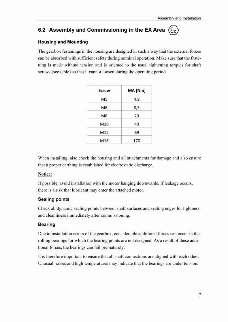
The gearbox fastenings in the housing are designed in such a way that the external forces can be absorbed with sufficient safety during nominal operation. Make sure that the faste-ning is made without tension and is oriented to the usual tightening torques for shaft screws (see table) so that it cannot loosen during the operating period.
Screw MA [Nm]
M5 4,8
M6 8,3
M8 20
M10 40
M12 69
M16 170
When installing, also check the housing and all attachments for damage and also ensure that a proper earthing is established for electrostatic discharge.
Notice:
If possible, avoid installation with the motor hanging downwards. If leakage occurs, there is a risk that lubricant may enter the attached motor.
Sealing points
Check all dynamic sealing points between shaft surfaces and sealing edges for tightness and cleanliness immediately after commissioning.
Bearing
Due to installation errors of the gearbox, considerable additional forces can occur in the rolling bearings for which the bearing points are not designed. As a result of these addi-tional forces, the bearings can fail prematurely.
It is therefore important to ensure that all shaft connections are aligned with each other. Unusual noises and high temperatures may indicate that the bearings are under tension.

Assembly and Installation
8
Shafts and Connections
Faulty assembly can cause additional bending, transverse or longitudinal stresses on the gearbox shafts. The shafts could break. Therefore, please ensure that the installation is carried out in accordance with the regulations. In the case of positive shaft-hub connec-tions, make sure that the connections are not installed with excessive play or impermissi-ble misalignments. Damage could be caused by impact stresses, fretting corrosion or ad-ditional forces resulting in failure of the connection. Splined shafts and key shafts must be lubricated before installation to prevent fretting corrosion wear and premature failure.
For force-fit shaft-hub connections, compliance with tolerances, surface qualities and a grease-free joint are decisive. A suitable adhesive must be used for adhesive-shrink joints.
Coupling
When installing couplings, impermissible axial and radial misalignments must be avoided. This could cause damage due to impact stresses, fretting corrosion or additional forces, which could result in failure of the coupling or other components.
The servo couplings must be secured by means of clamping screws and the specified tightening torques.
For the assembly of the coupling hub on the engine side, please also observe the in-structions enclosed with the delivery.
Shrink discs
Narrow, open gaps < 3mm must be avoided in dust areas. In the case of friction-locked shrink disc connections, compliance with tolerances, surface qualities and grease-free mounting surfaces is crucial. The screws of the clamping set or shrink disc must be tigh-tened correctly and with the prescribed torque. Avoid contact of the clamping set parts or shrink discs with stationary components.
Servo coupling Rotex GS
Size 19 24 28 38
Tightening torque TA [Nm] motor side 10 10 25 49
Tightening torque TA [Nm] gear side 3 6 6 10
Assembly and Installation
9
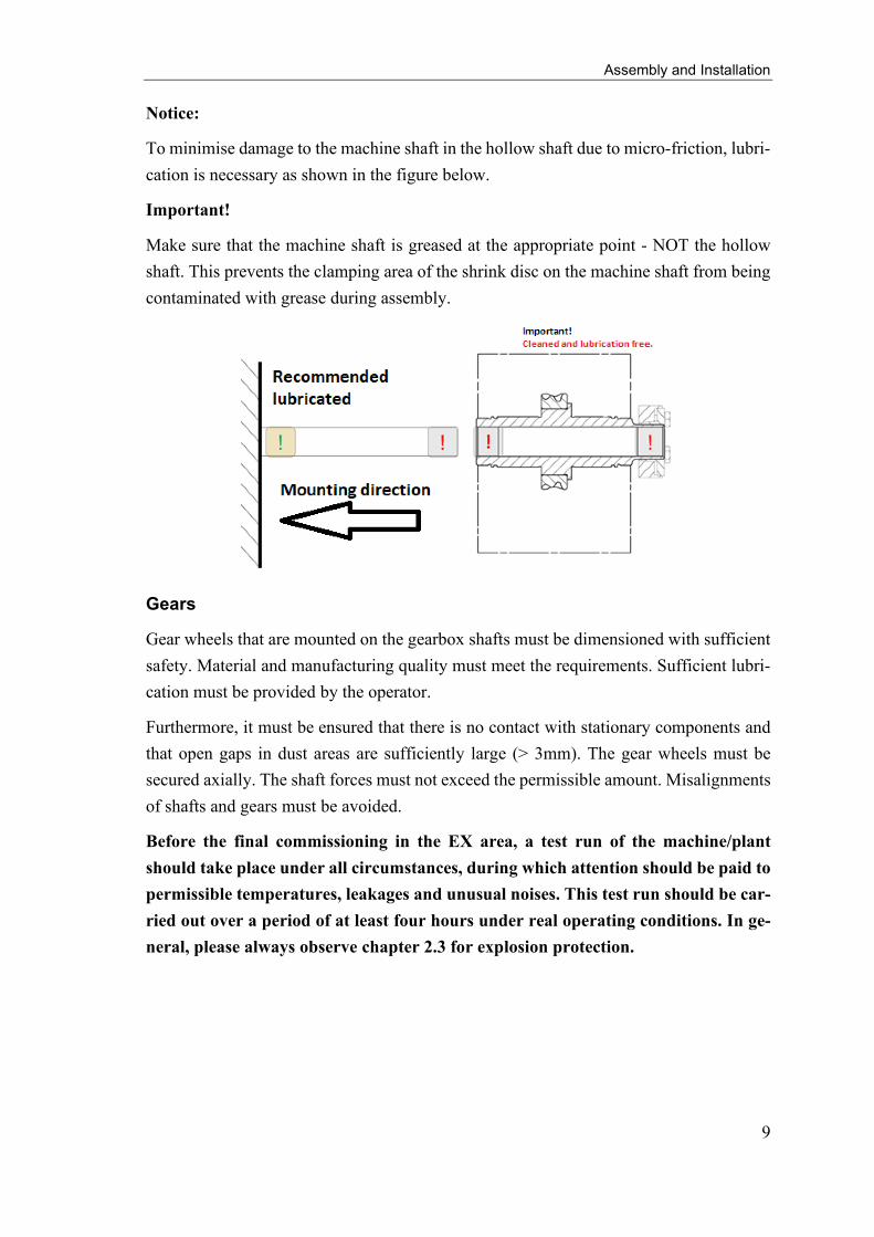
Notice:
To minimise damage to the machine shaft in the hollow shaft due to micro-friction, lubri-cation is necessary as shown in the figure below.
Important!
Make sure that the machine shaft is greased at the appropriate point - NOT the hollow shaft. This prevents the clamping area of the shrink disc on the machine shaft from being contaminated with grease during assembly.
Gears
Gear wheels that are mounted on the gearbox shafts must be dimensioned with sufficient safety. Material and manufacturing quality must meet the requirements. Sufficient lubri-cation must be provided by the operator.
Furthermore, it must be ensured that there is no contact with stationary components and that open gaps in dust areas are sufficiently large (> 3mm). The gear wheels must be secured axially. The shaft forces must not exceed the permissible amount. Misalignments of shafts and gears must be avoided.
Before the final commissioning in the EX area, a test run of the machine/plant should take place under all circumstances, during which attention should be paid to permissible temperatures, leakages and unusual noises. This test run should be car-ried out over a period of at least four hours under real operating conditions. In ge-neral, please always observe chapter 2.3 for explosion protection.

Operation
10
7 Operation
7.1 Lubrication
As the efficiency and service life of worm gearboxes in particular depend to a large extent on the oil quality used, we recommend that you only fill in the qualities specified on the gearbox type plate or in the lubricant tables. In the case of a gearbox designed for synthe-tic lubrication, mineral oil must never be used when changing the oil.
When changing to a different lubricant, Mädler recommends flushing the gearbox with the new lubricant before filling it with the new lubricant.
Synthetic lubricants must not be mixed with mineral lubricants. Also, not all synthetic lubricants can be mixed with each other. When filling the lubricant, make sure it is clean - use a filter or fine sieve if necessary.
For the lubricant quantities, please refer to the lubricant table under point 7.2.
Under normal operating conditions, gearboxes with a synthetic oil filling can be used for a long time without the need for an oil change - oil changes are recommended after ap-prox. 15,000 operating hours or after five years at the latest. The synthetic gear oils listed in the lubricant table enable high performance, reduce friction, have a very good vis-cosity-temperature behaviour and offer excellent wear protection. Furthermore, they are characterised by a very good ageing resistance. The synthetic gear oils can be used in a temperature range from -30 °C to +140 °C. Under extreme conditions, special quality seals are required.
Filled with food grade NSF-H1 lubricant on delivery (FDA approved).
7.2 Lubricant Quantities and Oil Viscosities
The lubricant quantities and viscosities stated are valid for all operating positions and gear ratios.
Gearbox size 40 50 63 80
Approx. filling quantity (ltr.) 0,25 0,35 0,70 1,25
Oil viscosity for standard version (ISO VG) 460 460 460 220

Operation
11
7.3 Lubricants and Manufacturer
For reasons of space, the table cannot contain all products. Lubricants from other manu-facturers such as Total, Shell, Lubcon, Bechem and alternative products from the listed manufacturers can be requested from the respective lubricant manufacturers. In case of doubt, alternative products should always be used in consultation with Mädler in order to avoid problems.
Lubricant type
Quality ISOVG
H1 lubricants (NSF-registered products for the food industry)
Polyglycols
CLP PG 220
Optileb
GT 1800/220
Cassida
WG 220
Klübersynth
UH1 6-220
Glygoyle 220
CLP PG 460
Optileb
GT 1800/460
Cassida
WG 460
Klübersynth
UH1 6-460
Glygoyle 460
Lubricating greases
(Rolling bearing + RWDR)
- Optileb
GR UF 2 -
Klübersynth
UH1 14-222
Mobilgrease
FM 222

Operation
12
7.4 Interferences
If you notice any malfunctions during operation, first try to identify and remedy the type of malfunction using the overview below. If it is a malfunction that cannot be remedied by you, please contact us.
Malfunction Possible cause Remedy
Oil leaks: • on the shaft seal on
the drive side • on the shaft sealing
ring on the output side
• on the gearbox cover
• on the motor flange • on the engine shaft seal
A Shaft seal ring defective or Shaft damaged
B O-ring on gearbox cover leaking
C Surface seal damaged D Internal pressure too high
A + B Call customer service C Tighten the screws on the
gearbox cover and observe the gearbox. If oil continues to leak out: Call customer service
D Bleed gearbox
Unusual, even Running noises
A Rolling/grinding noise: Bearing
damage B Knocking sound: Iregularity in toothing
A + B
Check oil, change bear-ings, call customer service
Unusual, uneven running noises
Foreign bodies in the oil
Check oil, shut down drive, call customer service
Unusually high temperatures at the housing
A Too little oil
B Gear teeth or bearing defective
A Check / correct oil level
B Call customer service
Output shaft does not rotate alt-hough motor is running or input shaft is rotated.
A Shaft-hub connection or gearing broken
B Coupling or shrink disc slips through
A Send in gearbox/geared motor for repair B Check assembly and compo-nents, if necessary with the help of the corresponding assembly instructions.

Operation
13
7.5 Operation in the EX-Area
Housing and Housing parts
The components are designed so that the internal and external forces can be absorbed with sufficient safety in nominal operation. Thermally, the performances are dimensioned so that the surface temperatures do not exceed 135 °C under permissible operating con-ditions and at a maximum ambient temperature of 40 °C.
The thermal power limits and the maximum circumferential speeds of gears and shafts under radial shaft seals are taken into account when specifying performance data. This prevents damage due to thermal overload and insufficient lubrication.
Make sure that overloads are avoided and that any damage (e.g. cracks) in the enclosure wall is detected in good time through regular inspections. Additional subsequently in-serted holes in the enclosure wall must be secured accordingly. Also make sure that none of the fixings on the cover fuses become loose or damaged during operation.
Static Seals
The seals can be damaged by mechanical, thermal or chemical influences or loosening of fastening elements such as screws or circlips and lose their function, lubricant can leak out.
If there is a loss of lubricant due to incorrect handling or overloads, this leads to tempe-rature increases and damage to moving parts in the gearbox.
Dynamic seals
All seals (radial shaft seals) are installed according to the manufacturer's instructions. The intended operating conditions also correspond to the manufacturer's specifications. The manufacturer gives guideline values for overtemperature at the sealing edge, according to which a maximum of 40K overtemperature occurs at the sealing edge to the oil sump at shaft speeds of up to 6,000min-1, provided the housing has pressure compensation and the sealing ring is sufficiently lubricated. Dynamic seals are wearing parts and there is currently no reliable information on their service life.
The sealing point (radial shaft seal/shaft surface) can be damaged during operation by the effects of force, acids, alkalis, solvents, certain oils and UV rays as well as dust and dirt from inside or outside. Excessive temperatures and corrosion during operation can also damage the sealing surface.
Ensure that the sealing points are clean and free of damage during operation.

Operation
14
Hermetic pressure equalisation
The integrated hermetic pressure compensation is designed so that the internal pressure and temperature do not exceed permissible values when operating under permissible conditions of use.
Bearings
All bearings are provided with oil or lifetime grease lubrication. By taking into account all the rolling bearing manufacturer's specifications and optimum alignment and ad-justment, additional stresses are avoided.
The surface temperatures in the area of the bearings cannot exceed 135 °C under permis-sible operating conditions and at 40 °C ambient temperature. In addition, the bearings of the high-speed drive side are cooled by the oil.
Continuous or repetitive torque peaks can lead to premature failure of a rolling bearing. Transverse forces introduced externally via shafts by wheels, friction rollers, gear wheels or belt pulleys can also damage bearings. Ensure that the maximum load on the gearbox is in accordance with the permissible manufacturer's specifications.
Dust and dirt, from outside or inside, can also damage the rolling bearings.
Shafts and shaft-hub connections
No additional heat is generated from the shaft-hub connection. The shafts are designed to be fatigue-proof for rated operation. Failure of the shaft material is not to be expected under permissible load conditions.
The operator must ensure that overloads or torque peaks and additional radial loads (e.g. due to attached wheels, friction rollers, toothed wheels or pulleys) are avoided to an in-admissible extent.
The positive shaft-hub-connections (feather keys, splined shafts, dowel screws and dowel pins) are designed to be fatigue-proof for nominal operation. Ensure that the spline and key shafts are sufficiently lubricated and that overloads due to temporary or permanent torque peaks resulting in excessive compressive and shear stresses are avoided.
The non-positive shaft-hub connections (longitudinal and transverse press fits, ad-hesive-shrink connections) are designed to be fatigue-proof for nominal operation. A single torque overload of a friction-locked shaft-hub connection can already greatly reduce the transmittable torque. Additional longitudinal and bending stresses also reduce the load capacity of the connection. It must be ensured that the permissible tor-ques and forces are not exceeded.

Operation
15
Couplings
The servo couplings used have a type examination certificate for use in category 2G and 2D.
Clamping sets and shrink discs
No additional heat is generated by the clamping sets and shrink disc connections. The connections are designed to be fatigue-proof for nominal operation. In the event of slippage, a considerable amount of heat can be generated. Avoid contact between the clamping set parts and stationary components. Narrow, open gaps must be prevented in dust areas. Clamping sets must be covered by suitable constructive measures.
Even a single torque overload of a friction-locked clamping set or a shrink disk connec-tion can greatly reduce the transmissible torque. Additional longitudinal and bending stresses also reduce the stressability of the connection.Ensure that the permissible tor-ques and forces are not exceeded.
Gears
The calculated service life at nominal torque is at least 12,000 hours. After that, the wheel-sets must be checked and replaced if necessary. Failure of the gear material is not to be expected under permissible load conditions.
Temporary or continuous torque peaks can cause tooth flanks or tooth roots to fail. If overload does not cause breakage, at least an increase in temperature must be expected.
Make sure that overloads, especially as a result of impermissibly high torques, are avoided.
Important: If the gearbox is operated in the EX range, the backlash must not be adjusted by turning the housing cover (see also notes on backlash adjustment, item 8.3).
Lubricants
Gearboxes for use in potentially explosive atmospheres may only be filled with synthetic oils based on polyglycol. The flash point for the recommended lubricants is generally above 250 °C. For this purpose, certain lubricant types are recommended and the lubricant quantities are prescribed.
The recommended lubricants are equally suitable for the lubrication of gears, rolling bearings and seals. The lubricant is subject to an ageing process and increasing contami-nation in the course of its service life. As a result, the lubricating properties deteriorate. Therefore, the lubricant can only be used for a limited time and must be renewed at certain intervals.

Operation
16
The service life depends on the type of lubricant and the lubricant load, but it is at least 15,000 operating hours. After that, or after five years at the latest, the lubricant must be changed.
The type of lubricant used has a decisive influence on temperature development and wear.
Lubricants with different bases and from different manufacturers must not be mixed. Base oils, additives and thickeners can be incompatible with each other and seriously impair the properties of the lubricant.
When refilling lubricant, only the lubricant specified on the type plate may be used. When changing oil with a new lubricant product, the gearbox housing must first be flushed with the new lubricant.
The operator is responsible for using a suitable lubricant. The corresponding recommen-dations can be found under point 7.3. In general, please always observe chapter 2.3 for explosion protection.

Inspection and Maintenance
17
8 Inspection and Maintenance
8.1 General Information
The inspection and maintenance intervals are highly dependent on the application: A drive that only occasionally performs positioning tasks in a clean environment at room temperature requires less effort than a drive that is used in three-shift operation, in a dirty environment and at high temperatures.
The inspection and maintenance intervals are usually based on the intervals of the entire machine or system, which are specified by the manufacturer. In some applications, sen-sors are provided on the drives to permanently monitor the condition (current consump-tion, torques, temperatures, vibrations).
In any case, a drive should be checked and maintained regularly. Attention should be paid to the following:
• Contamination
• Condition of housing, cover and fastenings
• Condition and function of pressure equalisation
• Leakage at sealing rings and covers
• Bearing noises
• Gear noise and backlash
• Shaft-hub connections and couplings
• Temperature at the housing surface
• Oil leakage
• Lubricant condition in general (oil samples)
• Recommended oil change intervals
With these measures, you maintain the operability of your machine or system, avoid un-foreseen malfunctions and reduce the risk of accidents.

Inspection and Maintenance
18
8.2 Inspection and Maintenance in the Ex-Area
Gearbox housing
Make sure by regular checks that the fixings on the gearbox housing and the cover fuses do not become loose or damaged and that any cracks in the housing wall due to overloads or extreme force are detected in good time.
Layers of dust and dirt on the surface of the enclosure can impair heat dissipation and thus lead to impermissibly high temperature development.
Ensure that regular inspection and cleaning of the surfaces is carried out. The ingress of dust and dirt into the housing will impair the lubricating effect and damage the moving parts, causing wear and excessive temperature.
Take appropriate measures to ensure that no dust or dirt gets into the housing during maintenance work or cleaning of the system. If there is any suspicion of contamination, at least change the lubricant, check the temperature and carry out a noise test of the gear-box. If large amounts of foreign matter enter the gearbox, it must be cleaned or replaced by specialists.
During normal operation, no lubricant escapes from the housing. If lubricant is lost due to operating errors or overloads, this leads to excessive temperatures and damage to mo-ving parts.
Monitor and inspect regularly so that lubricant leakage is detected and remedied in good time. If a significant loss of lubricant is suspected, eliminate the cause of the leakage, refill the lubricant, check the temperature and carry out a noise check of the gearbox.
Seals
The elastomers of the sealing rings are not resistant to some gear oils and greases. These oils and greases must not be used, otherwise the elastomer will be damaged. Only lubri-cants according to the type plate or manufacturer's specifications may be filled in.
Ensure that the sealing points retain their function through appropriate measures and re-gular checks (cleanliness of the sealing point, no insufficient lubrication due to oil loss) and that in the event of lubricant leakage, this is detected in good time. If a significant loss of lubricant is suspected, the cause of the leakage must be eliminated, the prescri-bed lubricant must be refilled, the temperature must be checked and a noise check of the gearbox must be carried out. Lubricant may only be filled by qualified personnel.
Inspection and Maintenance
19
Hermetic pressure equalisation
It must be ensured that the filter disc in the pressure compensation cover is free of dirt and that air passage is guaranteed. In addition, it must be checked whether lubricant can be seen leaking in the area of the pressure equalisation (leaking lubricant can indicate damage to the pressure equalisation element).
Bearings
Ensure that the gearbox is loaded according to the manufacturer's permissible specifica-tions. Regular checks of temperature, noise and lubrication prevent sudden failure. Re-placement is recommended after the service life has been reached. Repairs to the roller bearings may only be carried out by qualified personnel.
Gearbox shafts
Any overloading of the gearbox shafts must be avoided. Make sure that any cracks re-sulting from an overload in a shaft are detected at an early stage through regular inspec-tions.
Shaft-hub connections
Overloads due to impermissibly high torques must be avoided in all shaft-hub connec-tions (positive and non-positive). Furthermore, in the case of positive connections, en-sure that there is sufficient grease and check this regularly. Shaft-hub connections must be checked regularly for impermissible play and transmissible torques.
Couplings
Ensure that overloads due to impermissibly high torques are avoided and check the coupling ring gear for damage and the coupling for impermissible play.
Gears
Ensure that the gearbox is maximally loaded according to the manufacturer's permissible specifications. Regular checks of temperature, noise and lubrication prevent sudden fai-lure. Replacement is recommended after the service life has been reached. Repairs may only be carried out by qualified personnel.
Lubricants
Only lubricants according to the type plate or manufacturer's specifications may be filled in. A sufficient quantity must be ensured. Regular inspection of the lubricant quantity and the sealing points is recommended.
Inspection and Maintenance
20
Lubricant may only be changed and refilled by qualified personnel. For sensible change intervals, see Point 7.
Dust, dirt and water in the lubricant can severely impair the lubrication of the moving parts. Ensure that excessive dust and dirt deposits at sealing points or vents are avoided. No dust, dirt or water may get into the interior of the gearbox. Especially when cleaning the system, avoid direct impact of a sharp cleaning jet on seals and vents. The operator must ensure that seals and vents are free of damage by carrying out regular checks. A defective seal or vent must be inspected and repaired or replaced by qualified personnel.
Regular inspections should be carried out to ensure that lubricant leaks are detected and rectified in good time. In the event of significant loss, top up with the appropriate lubri-cant, check the temperature and carry out a noise check of the gearbox.
Lubricants with different bases and from different manufacturers must not be mixed. Base oils, additives and thickeners may be incompatible with each other and seriously impair the properties of the lubricant.
When changing the oil with a new lubricant product, the gearbox housing must first be flushed with the new lubricant. In general, please always observe chapter 2.3 for ex-plosion protection.

Inspection and Maintenance
21
8.3 Adjusting the backlash
All versions of the ZM/S servo worm gearboxes allow for a limited adjustment of the existing backlash in the gearing if required. This is possible by evenly turning the housing cover (pos. 2 / 2.1, see 3) and thus changing the centre distance. More detailed in-structions are available on request.
Important:
• The possibility of adjusting the circumferential backlash in the gearing (changing the delivery condition) must be clarified with our technical service. Changes to the de-livery condition are not permitted without consultation and express consent. This is par-ticularly important for operation in explosion-risk areas (see point 7.5).
• In the event of an unauthorised change to the delivery condition, all warranty claims will be invalidated.
Attention:
Improper execution may cause severe damage to the gearing and the gearbox, e.g. due to jamming.

Recycling
22
9 Recycling The gearbox should be dismantled when it has reached the end of its service life and the components should be sorted and sent for material recycling.
The following components are the most important recyclable materials:
- Housing parts (steel, aluminium)
- Gear wheels (steel, bronze)
- Lubricants (petrochemical raw materials)
Sealing materials are hazardous waste and cannot be recycled.