Mounting and Operating Instructions EB 8392 EN Solenoid... · · 2012-11-19Mounting and Operating...
12
Series 3710 Reversing Amplifier Type 3710 Mounting and Operating Instructions EB 8392 EN Edition August 2011 Fig. 1 · Type 3710 Reversing Amplifier in normal version and with pressure gauges for Y 1 and Y 2
Transcript of Mounting and Operating Instructions EB 8392 EN Solenoid... · · 2012-11-19Mounting and Operating...

Series 3710
Reversing Amplifier Type 3710
Mounting andOperating Instructions
EB 8392 ENEdition August 2011
Fig. 1 · Type 3710 Reversing Amplifier in normal version and with pressure gauges for Y1 and Y2

Contents Page
1 Design and principle of operation. . . . . . . . . . . . . . . . . . . . 31.1 Versions . . . . . . . . . . . . . . . . . . . . . . . . . . . . . . . . 41.2 Technical data . . . . . . . . . . . . . . . . . . . . . . . . . . . . . 5
2 Attachment to positioner . . . . . . . . . . . . . . . . . . . . . . . . 62.1 Attachment to Types 3767, 3766, 3780 and Type 3730
(angle of rotation >90°) Positioners and to Type 3768 Limit Switchmounted on a rotary actuator acc. to VDI/VDE 3845 . . . . . . . . . . 6
2.2 Attaching Type 4708-54 Supply Pressure Regulator . . . . . . . . . . . 82.3 Mounting with older models of Type 3766, 3767 and 3780 Positioners . . 9
3 Pneumatic connections . . . . . . . . . . . . . . . . . . . . . . . . . 93.1 Pressure gauges . . . . . . . . . . . . . . . . . . . . . . . . . . . . 10
4 Troubleshooting . . . . . . . . . . . . . . . . . . . . . . . . . . . . 10
5 Accessories for Type 3710. . . . . . . . . . . . . . . . . . . . . . . 11
6 Dimensions in mm . . . . . . . . . . . . . . . . . . . . . . . . . . 12
2 EB 8392 EN
Contents
General safety instructions
� The device may only be mounted, started up or operated by trained and ex-perienced personnel familiar with the product.According to these Mounting and Operating Instructions, trained personnelrefers to individuals who are able to judge the work they are assigned toand recognize possible dangers due to their specialized training, theirknowledge and experience as well as their knowledge of the relevant stan-dards.
� Proper shipping and appropriate storage are assumed.
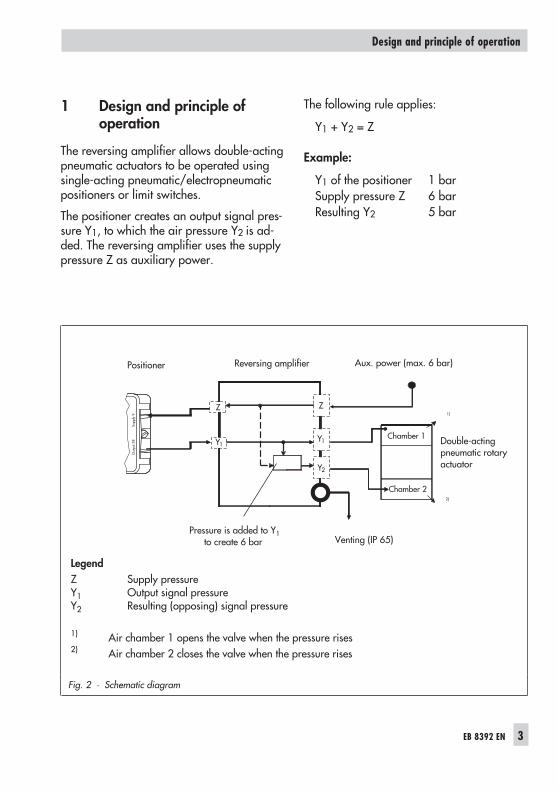
1 Design and principle ofoperation
The reversing amplifier allows double-actingpneumatic actuators to be operated usingsingle-acting pneumatic/electropneumaticpositioners or limit switches.
The positioner creates an output signal pres-sure Y1, to which the air pressure Y2 is ad-ded. The reversing amplifier uses the supplypressure Z as auxiliary power.
The following rule applies:
Y1 + Y2 = Z
Example:
Y1 of the positioner 1 barSupply pressure Z 6 barResulting Y2 5 bar
EB 8392 EN 3
Design and principle of operation
Z
Y2
Y1
Z
Y1
Out
put3
8Su
pply
9
Fig. 2 · Schematic diagram
LegendZ Supply pressureY1 Output signal pressureY2 Resulting (opposing) signal pressure
1) Air chamber 1 opens the valve when the pressure rises2) Air chamber 2 closes the valve when the pressure rises
Positioner Reversing amplifier Aux. power (max. 6 bar)
Chamber 1
1)
Pressure is added to Y1to create 6 bar Venting (IP 65)
Chamber 22)
Double-actingpneumatic rotaryactuator

1.1 Versions
4 EB 8392 EN
Design and principle of operation
Reversing amplifier Type 3710- 1 x x 1 0 x x 0
Housing material
Aluminum 0
Stainless steel 1 3
Connecting thread
ISO 228/1 - G ¼ 1
¼-18 NPT 2
Ambient temperature range
–25 … 80 °C 0
–50 … 80 °C 1 3
Degree of protection
IP 65, filter check valve made of polyamide 2
IP 65, filter check valve made of stainless steel 1.4305 3
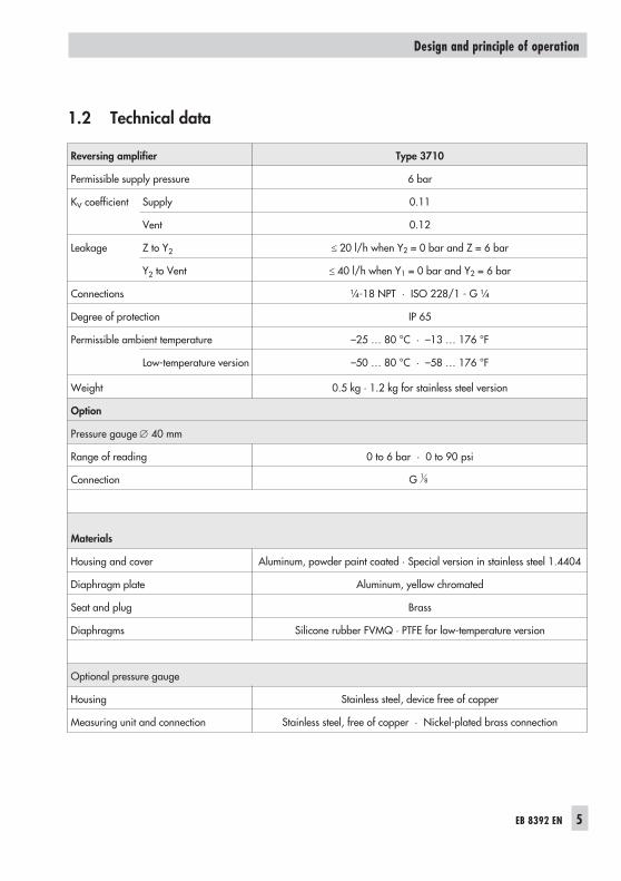
1.2 Technical data
EB 8392 EN 5
Design and principle of operation
Reversing amplifier Type 3710
Permissible supply pressure 6 bar
KV coefficient Supply 0.11
Vent 0.12
Leakage Z to Y2 � 20 l/h when Y2 = 0 bar and Z = 6 bar
Y2 to Vent � 40 l/h when Y1 = 0 bar and Y2 = 6 bar
Connections ¼-18 NPT · ISO 228/1 - G ¼
Degree of protection IP 65
Permissible ambient temperature –25 … 80 °C · –13 … 176 °F
Low-temperature version –50 … 80 °C · –58 … 176 °F
Weight 0.5 kg · 1.2 kg for stainless steel version
Option
Pressure gauge � 40 mm
Range of reading 0 to 6 bar · 0 to 90 psi
Connection G 18
Materials
Housing and cover Aluminum, powder paint coated · Special version in stainless steel 1.4404
Diaphragm plate Aluminum, yellow chromated
Seat and plug Brass
Diaphragms Silicone rubber FVMQ · PTFE for low-temperature version
Optional pressure gauge
Housing Stainless steel, device free of copper
Measuring unit and connection Stainless steel, free of copper · Nickel-plated brass connection
2 Attachment to positioner
The reversing amplifier is attached directlyto Types 3730, 3731, 3767*, 3766* and3780* Positioner and to Type 3768 LimitSwitch (*version index .05 and higher).
The reversing amplifier is screwed directlyonto the above listed positioners or limitswitch using two M5 screws.
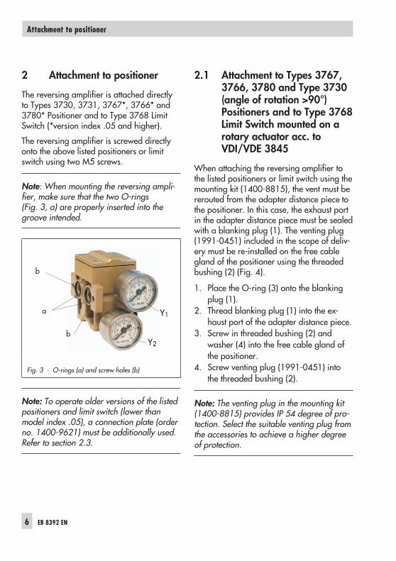
Note: When mounting the reversing ampli-fier, make sure that the two O-rings(Fig. 3, a) are properly inserted into thegroove intended.
Note: To operate older versions of the listedpositioners and limit switch (lower thanmodel index .05), a connection plate (orderno. 1400-9621) must be additionally used.Refer to section 2.3.
2.1 Attachment to Types 3767,3766, 3780 and Type 3730(angle of rotation >90°)Positioners and to Type 3768Limit Switch mounted on arotary actuator acc. toVDI/VDE 3845
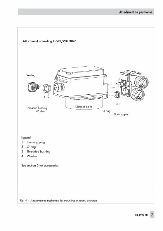
When attaching the reversing amplifier tothe listed positioners or limit switch using themounting kit (1400-8815), the vent must bererouted from the adapter distance piece tothe positioner. In this case, the exhaust portin the adapter distance piece must be sealedwith a blanking plug (1). The venting plug(1991-0451) included in the scope of deliv-ery must be re-installed on the free cablegland of the positioner using the threadedbushing (2) (Fig. 4).
1. Place the O-ring (3) onto the blankingplug (1).
2. Thread blanking plug (1) into the ex-haust port of the adapter distance piece.
3. Screw in threaded bushing (2) andwasher (4) into the free cable gland ofthe positioner.
4. Screw venting plug (1991-0451) intothe threaded bushing (2).
Note: The venting plug in the mounting kit(1400-8815) provides IP 54 degree of pro-tection. Select the suitable venting plug fromthe accessories to achieve a higher degreeof protection.
6 EB 8392 EN
Attachment to positioner
Fig. 3 · O-rings (a) and screw holes (b)
b
a
b
Y1
Y2
EB 8392 EN 7
Attachment to positioner
3 1
2 4
Fig. 4 · Attachment to positioners for mounting on rotary actuators
Attachment according to VDI/VDE 3845
Venting
Legend1 Blanking plug3 O-ring2 Threaded bushing4 Washer
See section 5 for accessories
Distance pieceO-ring
Blanking plug
Threaded bushingWasher
2.2 Attaching Type 4708-54Supply Pressure Regulator
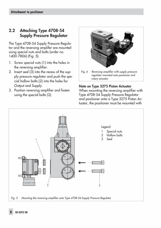
The Type 4708-54 Supply Pressure Regula-tor and the reversing amplifer are mountedusing special nuts and bolts (order no.1400-7806) (Fig. 5).
1. Screw special nuts (1) into the holes inthe reversing amplifier.
2. Insert seal (3) into the recess of the sup-ply pressure regulator and push the spe-cial hollow bolts (2) into the holes forOutput and Supply.
3. Position reversing amplifier and fastenusing the special bolts (2).
Note on Type 3275 Piston ActuatorWhen mounting the reversing amplifier withType 4708-54 Supply Pressure Regulatorand positioner onto a Type 3275 Piston Ac-tuator, the positioner must be mounted with
8 EB 8392 EN
Attachment to positioner
1
23
Fig. 5 · Mounting the reversing amplifier onto Type 4708-54 Supply Pressure Regulator
Legend1 Special nuts2 Hollow bolts3 Seal
Fig. 6 · Reversing amplifier with supply pressureregulator mounted onto positioner androtary actuator
the air holes located on the left-hand side.The supply pressure regulator can only bemounted onto the reversing amplifier in thismounting position.
2.3 Mounting with older modelsof Type 3766, 3767 and3780 Positioners
(lower than model index .05)Order no. 1400-9621
Note: Read section 2.1 before starting thisattachment.
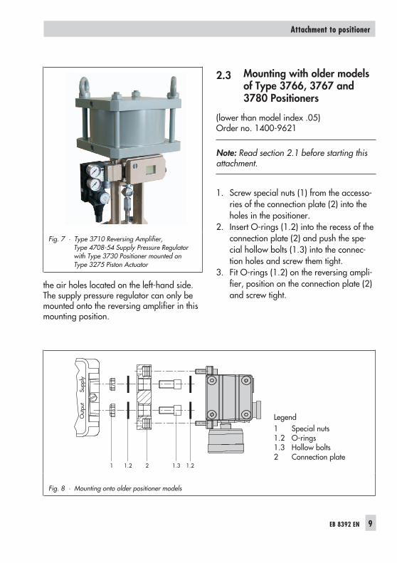
1. Screw special nuts (1) from the accesso-ries of the connection plate (2) into theholes in the positioner.
2. Insert O-rings (1.2) into the recess of theconnection plate (2) and push the spe-cial hollow bolts (1.3) into the connec-tion holes and screw them tight.
3. Fit O-rings (1.2) on the reversing ampli-fier, position on the connection plate (2)and screw tight.
EB 8392 EN 9
Attachment to positioner
Out
put
Supp
ly
1 1.2 1.21.32
Fig. 8 · Mounting onto older positioner models
Legend1 Special nuts1.2 O-rings1.3 Hollow bolts2 Connection plate
Fig. 7 · Type 3710 Reversing Amplifier,Type 4708-54 Supply Pressure Regulatorwith Type 3730 Positioner mounted onType 3275 Piston Actuator
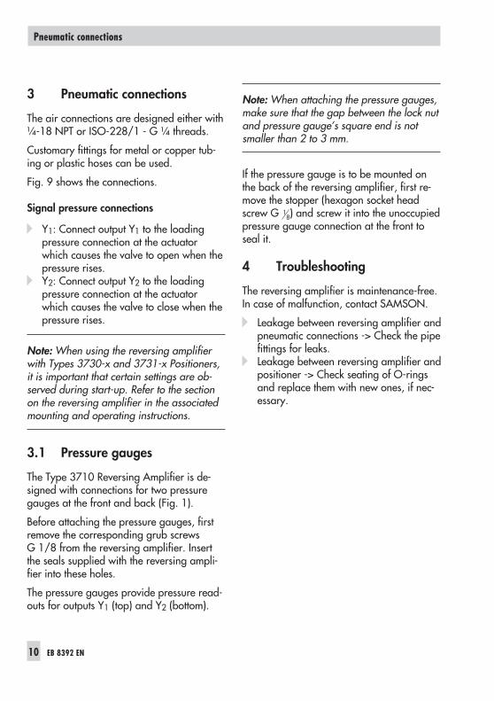
3 Pneumatic connections
The air connections are designed either with¼-18 NPT or ISO-228/1 - G ¼ threads.
Customary fittings for metal or copper tub-ing or plastic hoses can be used.
Fig. 9 shows the connections.
Signal pressure connections
� Y1: Connect output Y1 to the loadingpressure connection at the actuatorwhich causes the valve to open when thepressure rises.
� Y2: Connect output Y2 to the loadingpressure connection at the actuatorwhich causes the valve to close when thepressure rises.
Note: When using the reversing amplifierwith Types 3730-x and 3731-x Positioners,it is important that certain settings are ob-served during start-up. Refer to the sectionon the reversing amplifier in the associatedmounting and operating instructions.
3.1 Pressure gauges
The Type 3710 Reversing Amplifier is de-signed with connections for two pressuregauges at the front and back (Fig. 1).
Before attaching the pressure gauges, firstremove the corresponding grub screwsG 1/8 from the reversing amplifier. Insertthe seals supplied with the reversing ampli-fier into these holes.
The pressure gauges provide pressure read-outs for outputs Y1 (top) and Y2 (bottom).
Note: When attaching the pressure gauges,make sure that the gap between the lock nutand pressure gauge’s square end is notsmaller than 2 to 3 mm.
If the pressure gauge is to be mounted onthe back of the reversing amplifier, first re-move the stopper (hexagon socket headscrew G 1
8) and screw it into the unoccupiedpressure gauge connection at the front toseal it.
4 Troubleshooting
The reversing amplifier is maintenance-free.In case of malfunction, contact SAMSON.
� Leakage between reversing amplifier andpneumatic connections -> Check the pipefittings for leaks.
� Leakage between reversing amplifier andpositioner -> Check seating of O-ringsand replace them with new ones, if nec-essary.
10 EB 8392 EN
Pneumatic connections
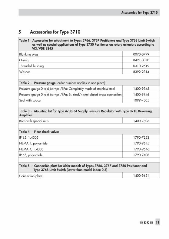
5 Accessories for Type 3710
EB 8392 EN 11
Accessories for Type 3710
Table 1 · Accessories for attachment to Types 3766, 3767 Positioners and Type 3768 Limit Switchas well as special applications of Type 3730 Positioner on rotary actuators according toVDI/VDE 3845
Blanking plug 0070-0799
O-ring 8421-0070
Threaded bushing 0310-2619
Washer 8392-2314
Table 2 · Pressure gauge (order number applies to one piece)
Pressure gauge 0 to 6 bar/psi/kPa; Completely made of stainless steel 1400-9945
Pressure gauge 0 to 6 bar/psi/kPa; St. steel/nickel-plated brass connection 1400-9946
Seal with spacer 1099-4305
Table 3 · Mounting kit for Type 4708-54 Supply Pressure Regulator with Type 3710 ReversingAmplifier
Bolts with special nuts 1400-7806
Table 4 · Filter check valves
IP 65, 1.4305 1790-7253
NEMA 4, polyamide 1790-9645
NEMA 4, 1.4305 1790-9646
IP 65, polyamide 1790-7408
Table 5 · Connection plate for older models of Types 3766, 3767 and 3780 Positioner andType 3768 Limit Switch (lower than model index 0.5)
Connection plate 1400-9621

6 Dimensions in mm
SAMSON AG · MESS- UND REGELTECHNIKWeismüllerstraße 3 · 60314 Frankfurt am Main · GermanyPhone: +49 69 4009-0 · Fax: +49 69 4009-1507Internet: http://www.samson.de EB 8392 EN 20
11-0
8
5686
13080
166
3086
Ø 101
8090
164
52 Output Y1
Output Y2
Supply (9)Output Y1
Output Y2
Fig. 9 · Dimensional drawings of Type 3710
164 15
Reversing amplifier mounted using aconnection plate (order no. 1400-9621,15 mm) onto Type 3766, 3767 orType 3780 Positioners (lower than index .05)