Mounting and Operating Instructions EB 8357 EN Positioners and...1 General safety instructions For...
12
Electric Limit Switch Type 4740 Mounting and Operating Instructions EB 8357 EN Edition November 2010 Fig. 1 · Type 4740 Limit Switch with mounting unit (1400-9922) for mounting onto the Type 3353 Angle Seat Valve or onto the Type 3354 Globe Valve
Transcript of Mounting and Operating Instructions EB 8357 EN Positioners and...1 General safety instructions For...

Electric Limit SwitchType 4740
Mounting andOperating Instructions
EB 8357 ENEdition November 2010
Fig. 1 · Type 4740 Limit Switch with mounting unit (1400-9922) for mounting onto the Type 3353 Angle SeatValve or onto the Type 3354 Globe Valve

Contents Page
1 General safety instructions . . . . . . . . . . . . . . . . . . . . . . . 3
2 Design and principle of operation. . . . . . . . . . . . . . . . . . . . 42.1 Technical data . . . . . . . . . . . . . . . . . . . . . . . . . . . . . 4
3 Mounting . . . . . . . . . . . . . . . . . . . . . . . . . . . . . . . . 53.1 Mounting unit. . . . . . . . . . . . . . . . . . . . . . . . . . . . . . 53.2 Mounting the limit switch onto the valve . . . . . . . . . . . . . . . . . 6
4 Connections . . . . . . . . . . . . . . . . . . . . . . . . . . . . . . 84.1 Electrical connection . . . . . . . . . . . . . . . . . . . . . . . . . . 84.2 Pneumatic connection
(with optional solenoid valve) . . . . . . . . . . . . . . . . . . . . . . 8
5 Setting the limit contacts . . . . . . . . . . . . . . . . . . . . . . . . 9
6 Dimensions in mm. . . . . . . . . . . . . . . . . . . . . . . . . . . 10
Contents
2 EB 8357 EN
DANGER!indicates a hazardous situation which, if notavoided, will result in death or serious in-jury.
WARNING!indicates a hazardous situation which, if notavoided, could result in death or serious in-jury.
NOTICEindicates a property damage message.
Note: Supplementary explanations, infor-mation and tips
Definitions of the signal words used in these instructions

1 General safety instructions
For your own safety, follow these instructions concerning the mounting, start-up and opera-tion of the limit switch:
� The limit switch must only be mounted, started up or operated by trained and experi-enced personnel familiar with the product.According to these Mounting and Operating Instructions, trained personnel refers to indi-viduals who are able to judge the work they are assigned to and recognize possible dan-gers due to their specialized training, their knowledge and experience as well as theirknowledge of the relevant standards.
� Any hazards that could be caused by the process medium, the operating pressure, thesignal pressure or by moving parts in the control valve are to be prevented by means ofthe appropriate measures.If inadmissible motions or forces are produced in the actuator as a result of the supplypressure, the supply pressure must be restricted by means of a suitable supply pressurereducing station.
To avoid damage to any equipment, the following also applies:
� Do not operate the limit switch with the back of the limit switch/vent opening facing up-wards.The vent opening must not be sealed when the limit switch is installed on site.
� Proper shipping and appropriate storage are assumed.
Note: The device with a CE marking fulfills the requirements of the Directives 94/9/EC(ATEX) and 89/336/EEC (EMC).The Declaration of Conformity is available on request.
EB 8357 EN 3
General safety instructions
Vent opening

2 Design and principle ofoperation
The Type 4740 Limit Switch is designed formounting onto the Type 3353 Angle SeatValve and the Type 3354 Globe Valve.The inductive proximity switches ormicroswitches cause signals to be sent to acontrol or alarm system when the valvetravel exceeds or falls below the adjustedlimit.
2.1 Technical data
The limit switch can optionally be fitted witha 3/2-way solenoid valve. When the incor-porated solenoid valve is energized, a sup-ply air pressure is applied to the actuator.When the solenoid valve is de-energized,the actuator is vented and the valve movesto its fail-safe position.
The switching points of the limit contacts canbe changed within the travel range. Refer tosection 5.
The limit switch is available in two versions,either with inductive proximity switches orwith microswitches.
4 EB 8357 EN
Design and principle of operation
Type 4740 Electric Limit Switch
Travel range 0 … 15 mm
Ambient temperature range –20 … 65 °C
Degree of protection IP 65
Weight Limit switch inc. solenoid valve, approx. 550 g · Mounting unit, approx. 180 g
Version with inductive proximity switches
Rated voltage 8.2 V DC over isolating switch amplifiers acc. to IEC 60947-5-6
Version with microswitches
Switching capacity 250 V AC, 16 (6) A
Materials
Housing Polyamide
Bonnet Polycarbonate
Filter Polyethylene
Mounting unit Stainless steel
Option: 3/2-way solenoid valve
Rated voltage 24 V DC
Capacity 1.5 W
Flow rate 55 ln/min (KV = 0.035)
Max. operating pressure 7 bar
Pneumatic connection Push-in L-connector QS-G 18 – 6 or ISO 228/1-G 1
8
3 Mounting
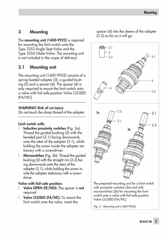
The mounting unit (1400-9922) is requiredfor mounting the limit switch onto theType 3353 Angle Seat Valve and theType 3354 Globe Valve. The mounting unitis not included in the scope of delivery!
3.1 Mounting unit
The mounting unit (1400-9922) consists of aspring-loaded adapter (3), a guided bush-ing (2) and a spacer (4). The spacer (4) isonly required to mount the limit switch ontoa valve with fail-safe position Valve CLOSED(FA/NC).
WARNING! Risk of cut injuryDo not touch the sharp thread of the adapter.
Limit switch with:� Inductive proximity switches (Fig. 2a):
Thread the guided bushing (2) with thebeveled part (2.1) facing downwardsonto the stem of the adapter (3.1), whileholding the screw inside the adapter sta-tionary with a screwdriver.
� Microswitches (Fig. 2b): Thread the guidedbushing (2) with the straight rim (2.2) fac-ing downwards onto the stem of theadapter (3.1), while holding the screw in-side the adapter stationary with a screw-driver.
Valve with fail-safe position:� Valve OPEN (FE/NO): The spacer is not
required.� Valve CLOSED (FA/NC): To mount the
limit switch onto the valve, insert the
spacer (4) into the sleeve of the adapter(3.2) as far as it will go.
EB 8357 EN 5
Mounting
3.1
3
3.2
2.1
2
2.2
4
Fig. 2 · Mounting unit (1400-9922)
2.2
2.1
2b
The prepared mounting unit for a limit switchwith proximity switches (2a) and withmicroswitches (2b) for mounting the limitswitch onto a valve with fail-safe positionValve CLOSED (FA/NC)
2.1
2.22a
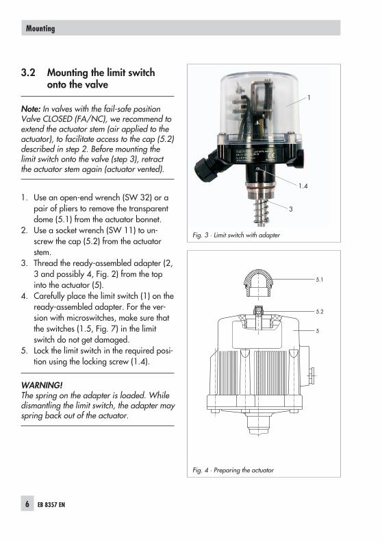
3.2 Mounting the limit switchonto the valve
Note: In valves with the fail-safe positionValve CLOSED (FA/NC), we recommend toextend the actuator stem (air applied to theactuator), to facilitate access to the cap (5.2)described in step 2. Before mounting thelimit switch onto the valve (step 3), retractthe actuator stem again (actuator vented).
1. Use an open-end wrench (SW 32) or apair of pliers to remove the transparentdome (5.1) from the actuator bonnet.
2. Use a socket wrench (SW 11) to un-screw the cap (5.2) from the actuatorstem.
3. Thread the ready-assembled adapter (2,3 and possibly 4, Fig. 2) from the topinto the actuator (5).
4. Carefully place the limit switch (1) on theready-assembled adapter. For the ver-sion with microswitches, make sure thatthe switches (1.5, Fig. 7) in the limitswitch do not get damaged.
5. Lock the limit switch in the required posi-tion using the locking screw (1.4).
WARNING!The spring on the adapter is loaded. Whiledismantling the limit switch, the adapter mayspring back out of the actuator.
6 EB 8357 EN
Mounting
Fig. 3 · Limit switch with adapter
3
1
1.4
5.1
5.2
5
Fig. 4 · Preparing the actuator

EB 8357 EN 7
Mounting
1
2
3
4
5
12
Fig. 5 · Mounting the limit switch
Mounting onto thelimit switch with
�
micro-switches
�
proximityswitches
Item 4 is not required for mountingthe limit switch onto valves withfail-safe position Valve OPEN(FE/NO)

4 Connections
4.1 Electrical connection
Risk of electric shock!For electrical installation, you are re-quired to observe the relevantelectrotechnical regulations and the ac-cident prevention regulations that applyin the country of use.
1. Undo the four screws on the housingcover and remove the housing cover.
2. Route the wires through the cable glandto the terminals as shown in Fig. 6.
3. Replace housing cover and fasten downwith the four screws.
4.2 Pneumatic connection(with optional solenoid valve)
The pneumatic connections are designed aspush-in L-connectors QS-G 1
8 – 6 or withISO-228/1-G 1
8 thread, depending on theversion.The following assignment applies:• Connection 1: Supply air• Connection 2: Output
NOTICEThe supply air must be dry and free from oiland dust. The maintenance instructions forupstream pressure reducing stations must beobserved.Blow through all air pipes and hoses thor-oughly prior to connecting them.
8 EB 8357 EN
Connections
+ –
81 82
+ –
51 52
+ –
41 42
Version with inductive proximity switches
Proximity switches Solenoid valve(option)
+ –
81 8252 5343 5141 42
Version with microswitches
Microswitches Solenoid valve(option)
Fig. 6 · Electrical connection

5 Setting the limit contacts
If it should be necessary to adjust the limitcontacts, the switching point can be adjustedwithin the travel range.
NOTICETo prevent destroying the limit switch, do notadjust the screw (1.2) before you haveloosened the screws (1.1). Observe thesequence described in steps 2 and 3!
1. Undo the four screws on the housingcover and remove the housing cover.
2. Undo the two screws (1.1) of the limitcontact (1.3) to be adjusted so that it canmove on the rail (1.4).
3. Adjust the limit contact (1.3) with thescrew (1.2):Turn the screw clockwise to move thelimit contact towards the top end posi-tion.Turn the screw counterclockwise to movethe limit contact towards the bottom endposition.
4. Lock the limit contact (1.3) in position us-ing the screws (1.1).
The second limit contact is adjusted in thesame way.
5. Replace the housing cover and fastendown with the four screws.
EB 8357 EN 9
Setting the limit contacts
Fig. 7 · Setting the limit contacts
1.2
1.4
1.1
1.5
1.3
Version with microswitches
1.2
1.4
1.1
1.3
Version with inductive proximity switches

6 Dimensions in mm
10 EB 8357 EN
Dimensions in mm
121
∅94 22M20 x 1.5
12Pneumaticconnection*
1: Supply air2: Output
* Version with solenoid valve:• Push-in L-connector QS-G 1
8 – 6 or• ISO 228/1-G 1
8
In the version without solenoid valves, thepneumatic connections are sealed byblanking plugs.

EB 8357 EN 11

SAMSON AG · MESS- UND REGELTECHNIKWeismüllerstraße 3 · 60314 Frankfurt am Main · GermanyPhone: +49 69 4009-0 · Fax: +49 69 4009-1507Internet: http://www.samson.de EB 8357 EN 20
11-0
1