Motortronics XLD Series Digital Solid State Soft Starter ... · XLD Series Digital Solid State Soft...
59
XLD Series Digital Solid State Soft Starter 39 - 1250A INSTALLATION & OPERATION MANUAL XLD SERIES Digital Solid State Soft Starter 39 - 1250 A ™ REV2 01032601MN © 2001, Motortronics. All Rights Reserved. Motortronics™ is a division of Phasetronics, Inc.™ Phone: 800.894.0412 - Fax: 888.723.4773 - Web: www.clrwtr.com - Email: [email protected]
Transcript of Motortronics XLD Series Digital Solid State Soft Starter ... · XLD Series Digital Solid State Soft...

XLD Series Digital Solid State Soft Starter 39 - 1250A
INSTALLATION & OPERATIONMANUAL
XLD SERIESDigital
Solid State Soft Starter39 - 1250 A
™
REV2 01032601MN
© 2001, Motortronics. All Rights Reserved. Motortronics™ is a division of Phasetronics, Inc.™
Phone: 800.894.0412 - Fax: 888.723.4773 - Web: www.clrwtr.com - Email: [email protected]

XLD Series Digital Solid State Soft Starter 39 - 1250A
Phone: 800.894.0412 - Fax: 888.723.4773 - Web: www.clrwtr.com - Email: [email protected]
Motortronics™
- 3 -
XLD Series Digital Solid State Soft Starter 39 - 1250A
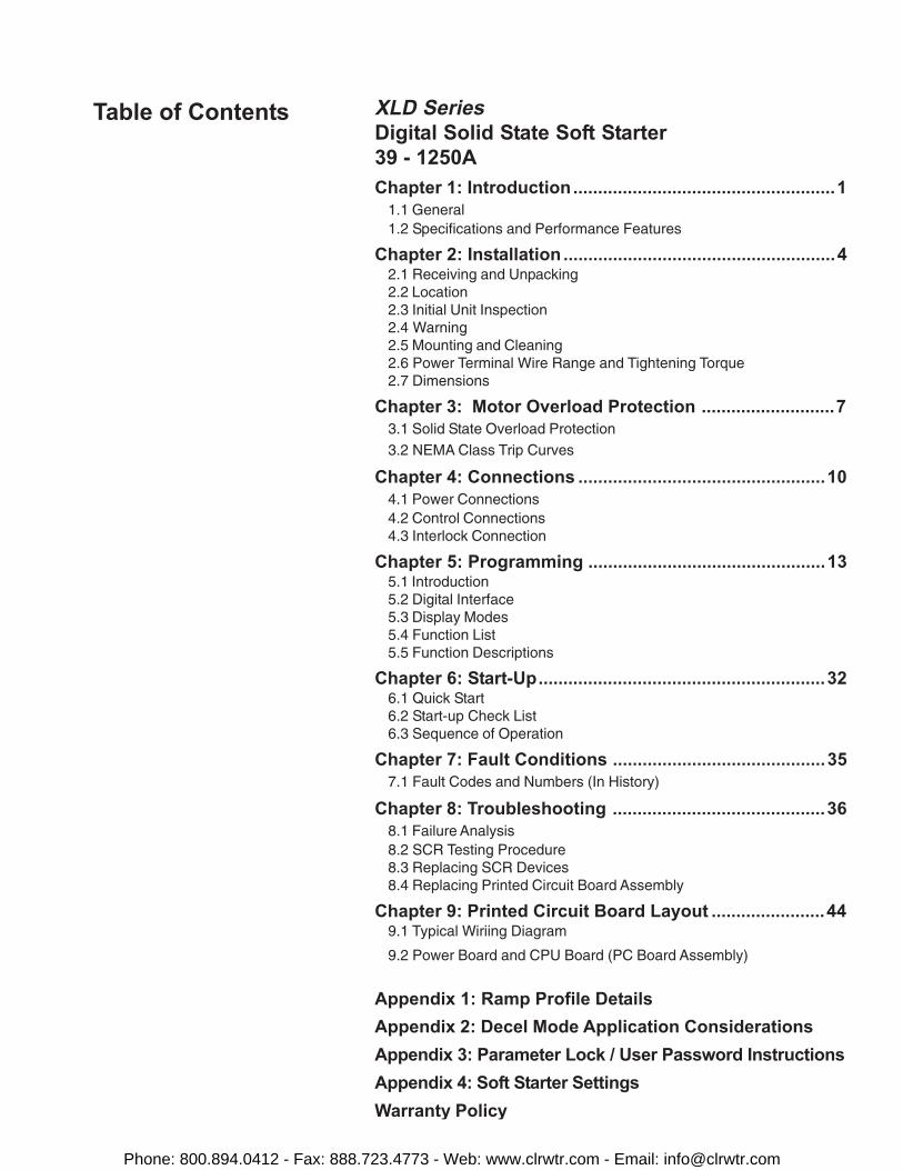
XLD SeriesDigital Solid State Soft Starter39 - 1250AChapter 1: Introduction.....................................................1
1.1 General1.2 Specifications and Performance Features
Chapter 2: Installation .......................................................42.1 Receiving and Unpacking2.2 Location2.3 Initial Unit Inspection2.4 Warning2.5 Mounting and Cleaning2.6 Power Terminal Wire Range and Tightening Torque2.7 Dimensions
Chapter 3: Motor Overload Protection ...........................73.1 Solid State Overload Protection3.2 NEMA Class Trip Curves
Chapter 4: Connections ..................................................104.1 Power Connections4.2 Control Connections4.3 Interlock Connection
Chapter 5: Programming ................................................135.1 Introduction5.2 Digital Interface5.3 Display Modes5.4 Function List5.5 Function Descriptions
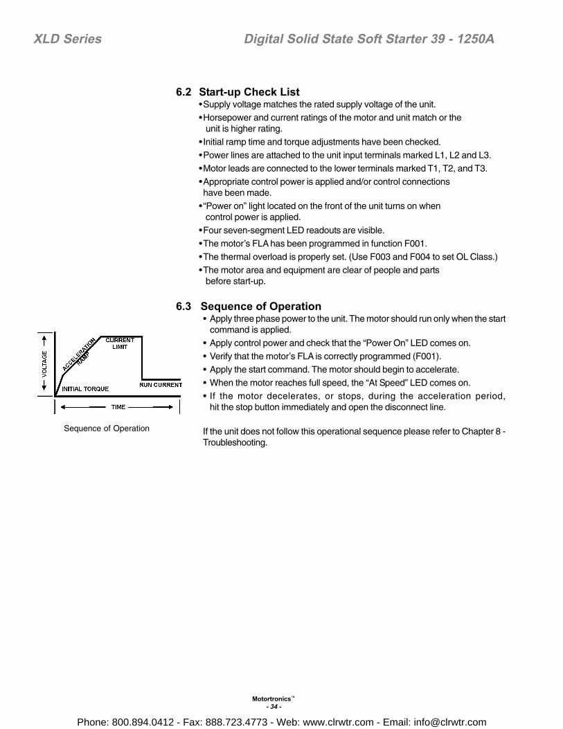
Chapter 6: Start-Up..........................................................326.1 Quick Start6.2 Start-up Check List6.3 Sequence of Operation
Chapter 7: Fault Conditions ...........................................357.1 Fault Codes and Numbers (In History)
Chapter 8: Troubleshooting ...........................................368.1 Failure Analysis8.2 SCR Testing Procedure8.3 Replacing SCR Devices8.4 Replacing Printed Circuit Board Assembly
Chapter 9: Printed Circuit Board Layout .......................449.1 Typical Wiriing Diagram
9.2 Power Board and CPU Board (PC Board Assembly)
Appendix 1: Ramp Profile DetailsAppendix 2: Decel Mode Application ConsiderationsAppendix 3: Parameter Lock / User Password InstructionsAppendix 4: Soft Starter SettingsWarranty Policy
Table of Contents
Phone: 800.894.0412 - Fax: 888.723.4773 - Web: www.clrwtr.com - Email: [email protected]

XLD Series Digital Solid State Soft Starter 39 - 1250A
Phone: 800.894.0412 - Fax: 888.723.4773 - Web: www.clrwtr.com - Email: [email protected]
Motortronics™
- 1 -
XLD Series Digital Solid State Soft Starter 39 - 1250A
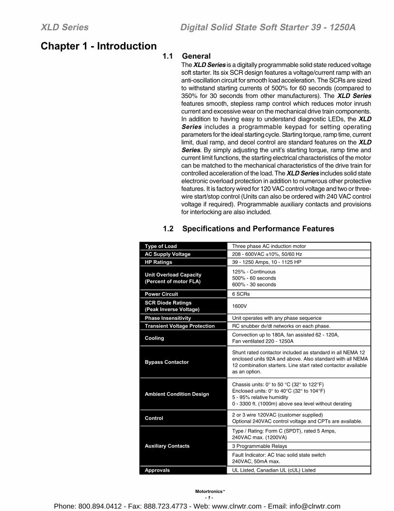
1.1 GeneralThe XLD Series is a digitally programmable solid state reduced voltagesoft starter. Its six SCR design features a voltage/current ramp with ananti-oscillation circuit for smooth load acceleration. The SCRs are sizedto withstand starting currents of 500% for 60 seconds (compared to350% for 30 seconds from other manufacturers). The XLD Seriesfeatures smooth, stepless ramp control which reduces motor inrushcurrent and excessive wear on the mechanical drive train components.In addition to having easy to understand diagnostic LEDs, the XLDSeries includes a programmable keypad for setting operatingparameters for the ideal starting cycle. Starting torque, ramp time, currentlimit, dual ramp, and decel control are standard features on the XLDSeries. By simply adjusting the unit’s starting torque, ramp time andcurrent limit functions, the starting electrical characteristics of the motorcan be matched to the mechanical characteristics of the drive train forcontrolled acceleration of the load. The XLD Series includes solid stateelectronic overload protection in addition to numerous other protectivefeatures. It is factory wired for 120 VAC control voltage and two or three-wire start/stop control (Units can also be ordered with 240 VAC controlvoltage if required). Programmable auxiliary contacts and provisionsfor interlocking are also included.
Chapter 1 - Introduction
1.2 Specifications and Performance Features
Type of Load Three phase AC induction motor
AC Supply Voltage 208 - 600VAC ±10%, 50/60 Hz
HP Ratings 39 - 1250 Amps, 10 - 1125 HP
Unit Overload Capacity(Percent of motor FLA)
125% - Continuous500% - 60 seconds600% - 30 seconds
Power Circuit 6 SCRs
SCR Diode Ratings(Peak Inverse Voltage) 1600V
Phase Insensitivity Unit operates with any phase sequence
Transient Voltage Protection RC snubber dv/dt networks on each phase.
Cooling Convection up to 180A, fan assisted 62 - 120A,Fan ventilated 220 - 1250A
Bypass Contactor
Shunt rated contactor included as standard in all NEMA 12enclosed units 92A and above. Also standard with all NEMA12 combination starters. Line start rated contactor availableas an option.
Ambient Condition Design
Chassis units: 0° to 50 °C (32° to 122°F)Enclosed units: 0° to 40°C (32° to 104°F)5 - 95% relative humidity0 - 3300 ft. (1000m) above sea level without derating
Control 2 or 3 wire 120VAC (customer supplied)Optional 240VAC control voltage and CPTs are available.
Type / Rating: Form C (SPDT), rated 5 Amps,240VAC max. (1200VA)
3 Programmable Relays
Fault Indicator: AC triac solid state switch240VAC, 50mA max.
Approvals UL Listed, Canadian UL (cUL) Listed
Auxiliary Contacts
Phone: 800.894.0412 - Fax: 888.723.4773 - Web: www.clrwtr.com - Email: [email protected]

Motortronics™
- 2 -
XLD Series Digital Solid State Soft Starter 39 - 1250A
1.2 Specifications and Performance Features Cont’d
Note 1: Enabled via programming
Two Stage ElectronicOverload Curves
Starting: Programmable for Class 5 through 30Run: Programmable for Class 5 through 30 when "At-Speed"is detected.
Overload Reset (Note 1) Manual (default) or automatic
Retentive Thermal MemoryOverload circuit retains thermal condition of the motorregardless of control power status. Unit uses real time clockto adjust for off time.
Dynamic Reset Capacity
Overload will not reset until thermal capacity available in themotor is enough for a successful restart. Starter learns andretains this information by monitoring previous successfulstarts.
Phase Current ImbalanceProtection (Note1)
Imbalance Trip Level: 5 - 30% currentbetween any two phasesImbalance Trip Delay: 1 -20 seconds
OverCurrent(Electronic Shear Pin)Protection (Note 1)
Trip Level: 50 - 300% of motor FLATrip Delay: 1 - 20 seconds
Load Loss Trip Protection(Note 1)
Under Current Trip Level: 10 -90 % of motor FLAUnder Current Trip Delay: 1 - 60 seconds
Coast Down (Back Spin)Lockout Timer (Note 1) Coast Down Time Range: 1 - 60 minutes
Starts-per-hour Lockout Timer(Note 1)
Range: 1 - 10 successful starts per hourTime between starts: 1 - 60 minutes between start attempts
Type / Rating Form C (SPST), Rated 5 amps240 VAC max, (1200 VA)
Run Indication Start/Stop or Start/End of Decel
At Speed Indication At Speed/Stop or At Speed/End of Decel
Acceleration Adjustments
Programmable Ramp Types: Voltage or Current Ramp(VR or CR)Starting Torque: 0 - 100% of line voltage (VR)or 0 - 600% of motor FLA (CR)Ramp Time: 1 to 120 secondsCurrent Limit: 200 - 600% (VR or CR)
Dual Ramp Settings4 Options: VR1+VR2; VR1+CR2; CR1+CR2; CR1+VR2Dual Ramp Control: Ramp #1 = Default,Ramp = #2 selectable via dry contact input
Deceleration Adjustments
Begin Decel Level: 0 - 100% of line voltageStop Level: 0 to 1% less than Begin Decel LevelDecel Time: 1 - 60 secondsProgrammable to decel or coast to stop upon overload trip
Jog SettingsJog function selected viadry contact closure input)
Voltage Jog: 5 - 100%Time of Voltage Jog: 1 - 20 secondsCurrent Jog: 100 - 500%
Kick Start Settings(Note 1)
Kick Voltage: 10 - 100%Kick Time: 0.1 - 2 seconds
Fault IndicationsShorted SCR, Phase Loss, Shunt Trip, Phase ImbalanceTrip, Overload, Overtemp, Overcurrent, Short Circuit, LoadLoss, or Any Trip
Lockout Indicator Coast Down Time, Starts Per Hour,Time Between Starts, and Any Lockout
Programmable Outputs
Advanced Motor Protection
Phone: 800.894.0412 - Fax: 888.723.4773 - Web: www.clrwtr.com - Email: [email protected]

Motortronics™
- 3 -
XLD Series Digital Solid State Soft Starter 39 - 1250A
1.2 Specifications and Performance Features Cont’d
Phase Currents 0 - 9999 Amps, Phase A, B, or C
Remaining Thermal Capacity 0 - 100% of available motor thermal capacity
Elapsed Time 0 - 9,999,000.0 hours, non resetable
Run Cycle Counter 0 - 99,990,000 run commands non resetable
Lockout Time Values Remaining time of any enabled lockout timer
Fault Codes Abbreviated fault codes, indicating trip and operating mode
Fault History Last 3 faults with Time and Date Stamps
Protocol Modbus RTU
Signal RS-485
Network Up to 247 devices per mode
Functionality Full operation, status view, and programmingvia communications port
LED Readout 4 digit alpha numeric, high brightness, 7 segment display
Keypad 7 functions keys with tactile feedback
Status Indicators 8 LEDs
Remote Mount Capability Up to 10 feet (3 meters) from chassis
Operating Memory DRAM loaded from EPROM and EEPROM at initialization
Factory Default Storage Flash EPROM, field replaceable
Customer Settings and Status Non-volatile EEPROM, no battery backup necessary
Real Time Clock Lithium ion battery for clock memory only,10+ years life span
Operator Interface
Clock and Memory
Metering Functions
Serial Communications
Phone: 800.894.0412 - Fax: 888.723.4773 - Web: www.clrwtr.com - Email: [email protected]

Motortronics™
- 4 -
XLD Series Digital Solid State Soft Starter 39 - 1250A
2.1 Receiving and UnpackingUpon receipt of the product you should immediately do the following:• Carefully unpack the unit from the shipping carton and inspect it for
shipping damage (if damaged, notify the freight carrier and file aclaim within 15 days of receipt).
• Verify that the model number on the unit matches your purchaseorder.
• Confirm that the ratings sticker on the unit matches or is greaterthan the motor’s HP and current rating.
2.2 LocationProper location of the XLD Series is necessary to achieve specifiedperformance and normal operation lifetime. The XLD Series shouldalways be installed in an area where the following conditions exist:
• Ambient operating temperature:Chassis unit: 0 to 50°C (32 to 122°F)Enclosed unit: 0 to 40°C (32 to 104°F)
• Protected from rain and moisture• Humidity: 5 to 95% non-condensing• Free from metallic particles, conductive dust and corrosive gas• Free from excessive vibration (below 0.5G)• Open panel units must be mounted in the appropriate type of
enclosure. Enclosure size and type must be suitable to dissipateheat generated by the soft starter. Contact factory for assistance insizing enclosures.
2.3 Initial Unit Inspection• Make a complete visual check of the unit for damage which may
have occurred during shipping and handling. Do not attempt to continueinstallation or start up the unit if it is damaged.
• Check for loose mechanical assemblies or broken wires which mayhave occurred during transportation or handling. Loose electricalconnections will increase resistance and cause the unit to functionimproperly.
• Prior to beginning the installation, verify that the motor and XLD unitare rated for the proper amperage and voltage.
2.4 Warning!Do not service equipment with voltage applied! The unit can bethe source of fatal electrical shocks! To avoid shock hazard,disconnect main power and control power before working onthe unit. Warning labels must be attached to terminals, enclosureand control panel to meet local codes.
Chapter 2 - Installation
Phone: 800.894.0412 - Fax: 888.723.4773 - Web: www.clrwtr.com - Email: [email protected]

Motortronics™
- 5 -
XLD Series Digital Solid State Soft Starter 39 - 1250A
2.5 Mounting and CleaningWhen drilling or punching holes in the enclosure, cover the electricalassembly to prevent metal filings from becoming lodged in areas whichcan cause clearance reduction or actually short out electronics. After workis complete, thoroughly clean the area and reinspect the unit for foreignmaterial. Make sure there is sufficient clearance (six inches) all around theunit for cooling, wiring and maintenance purposes. To maximize effectiveair flow and cooling, the unit must be installed with its heat sink ribs orientedvertically and running parallel to the mounting surface.
Warning!Remove all sources of power before cleaning the unit.
In dirty or contaminated atmospheres the unit should be cleaned on a regularbasis to ensure proper cooling. Do not use any chemicals to clean the unit.To remove surface dust use 80 to 100 psi, clean, dry compressed air only.A three inch, high quality, dry paint brush is helpful to loosen up the dustprior to using compressed air on the unit.
2.6 Power Terminal Wire Range and Tightening Torque
Note: All wiring must be sized according to NEC standards.
Model Number Wire range Torque lbs/in
XLD-39
XLD-48
XLD-62
XLD-78
XLD-92
XLD-120
XLD-150
XLD-180
XLD-220
XLD-288
XLD-360
XLD-414
XLD-476
XLD-550
XLD-718
XLD-862
XLD-1006
XLD-1150
XLD-1200
XLD-1250
#14 - #4 50
(2) #6 - 250 kcmil 325
#14 - #1/0 50
#18 - #4 20
(4) 300 kcmil - 800 kcmil 500
(2) #2 - 250 kcmil 375
(3) #2 - 600 kcmil 375
#6 - 250 kcmil 325
208V 230V 480V 600V 230V 400V
XLD-39 39 - - 25 30 11 18.5XLD-48 48 10 15 30 40 22XLD-62 62 15 20 40 50 15 30XLD-78 78 20 25 50 60 22 37XLD-92 92 25 30 60 75 45XLD-120 120 30 40 75 100 30 55XLD-150 150 40 50 100 125 45 75XLD-180 180 50 60 125 150 55 90XLD-220 220 60 75 150 200 110XLD-288 288 75 100 200 250 75 132XLD-360 360 100 125 250 300 110 160XLD-414 414 125 150 300 350 200XLD-476 476 - - 350 400 132 250XLD-550 550 150 200 400 500 160XLD-718 718 200 250 500 600 200 315XLD-862 862 250 300 600 700 400XLD-1006 1006 300 350 700 800XLD-1150 1150 350 400 800 900XLD-1200 1200 400 450 900 1000XLD-1250 1250 450 500 1000 1125
ModelNumber
KWMax
Amps
Max HP
Phone: 800.894.0412 - Fax: 888.723.4773 - Web: www.clrwtr.com - Email: [email protected]

Motortronics™
- 6 -
XLD Series Digital Solid State Soft Starter 39 - 1250A
2.7 Dimensions
A B C D E FXLD-39 to XLD-120 16.5 10 10 15.9 9 0.28
XLD-150 to XLD-180 20 20.1 12 18.5 17.5 0.44XLD-220 to XLD-288 27 20.1 11.2 25.5 17.5 0.44XLD-360 to XLD-550 29.5 20.1 11.5 25.5 17.5 0.44
XLD-718 to XLD-1006 45 33 12.8 43.3 31.3 0.44XLD-1150 to XLD-1250 33 33 15.2 31.2 31.2 0.44
XLD-39 to XLD-120 16.5 10 10 15.9 9 0.28XLD-150 to XLD-180 32.3 24.3 13.3 31.3 18 0.44XLD-220 to XLD-288 38.3 24.3 13.3 37.3 18 0.44XLD-360 to XLD-550 44.3 30.3 13.3 43.3 24 0.44
XLD-718 to XLD-1006 50.2 36.3 15.5 49.3 30 0.4XLD-1150 to XLD-1250
NEMA 4/4X XLD-39 to XLD-78 15.7 12.2 10 12 11 0.28XLD-92 to XLD-120 24 24 12.9 22.5 22.5 0.5
XLD-150 to XLD-288 36 30 16.9 34.5 28.5 0.5XLD-360 to XLD-550 48 36 16.9 46.5 34.5 0.5
XLD-718 to XLD-1006 72.1 48.1 20XLD-1150 to XLD-1250
NEMA12
Contact Factory
Contact Factory Contact FactoryFloor Mounted
Contact Factory
NEMA1
ModelNumber
MountingDimensionsEnclosure
PANEL
OverallDimensions
Phone: 800.894.0412 - Fax: 888.723.4773 - Web: www.clrwtr.com - Email: [email protected]

Motortronics™
- 7 -
XLD Series Digital Solid State Soft Starter 39 - 1250A
Chapter 3 - Motor Overload Protection3.1 Solid State Overload Protection
The XLD Series Starter provides true U.L. listed I2T Thermal Overload Protectionas a built-in function of the main digital processor. For maximum protection itsimulates the tripping action of a bimetallic overload relay, with the accuracyand repeatability of a digital control system, yet is adjustable over a wide rangeand can be easily programmed for different trip curves.
3.1.1 Thermal MemoryThe XLD Series microprocessor uses a sophisticated “Thermal Register” tokeep track of motor heating and cooling over time regardless of the starter’spower status. The XLD Series does not “forget” that the motor has been runningeven if power to the starter is turned off and back on. Continuous overloadprotection is provided based on the true thermal condition of the motor.
3.1.2 Thermal CapacityThe Thermal Register is displayed as a percentage. This percentage is themotor’s remaining thermal capacity. The percentage value begins at 100, showingthat the motor is cool. As the motor heats up or moves toward an overloadcondition, the percentage begins to drop. The Thermal Capacity is derived fromthe programmed motor nameplate Full Load Amps (FLA) in Function F001, theService Factor rating in Function F002, and the Overload Trip Class in FunctionsF003 and F004. Setting these functions to the proper values will provide maximumprotection yet eliminates nuisance tripping.
3.1.2.a Motor Full Load (FLA) SettingUse Function F001 to enter motor FLA as indicated on the motor nameplate.(Do not calculate for service factor, this is programmed separately in F002).
Note: If F001 is left at the factory default, the unit will not operate. If the user attemptsto start the XLD without entering the motor nameplate FLA into this Function,the XLD will Fault, and the display will read “nFLA” (for no Full Load Amps).
3.1.3 Disabling the Overload ProtectionThe Overload Protection feature can be disabled if absolutely necessary. Whenusing external devices such as Motor Protection Relays or when the XLD Series iswired downstream from an existing starter, this feature can be disabled to preventconflicts with external overload protection devices. When the XLD Series is controllingmultiple motors, Overload Protection must be disabled. Individual thermal overloadrelays must be installed on the motor leads going to each motor. To disable theOverload Protection function, use F005. (See Section 5.)
Warning: Do NOT disable Overload Protection unless another ThermalOverload Protection device exists in the circuit for all three phases.Running a motor without Overload Protection presents serious risk ofmotor damage or fire.3.1.3.a Manual ResetThe factory default setting is Manual Reset. This means that when the OverloadTrip is activated, the starter cannot be restarted without pressing the Reset key.The Overload Trip will not reset until the motor cools down. The Manual Resetfunction is also “trip free”. Holding in the Reset key will not prevent the OverloadTrip from activating and protecting the motor.
Note: When the Overload Trip activates, the Overload LED will glow solid. When themotor cools down, the LED will begin to flash, indicating that the OverloadTrip can be reset.
Phone: 800.894.0412 - Fax: 888.723.4773 - Web: www.clrwtr.com - Email: [email protected]
Motortronics™
- 8 -
XLD Series Digital Solid State Soft Starter 39 - 1250A
3.1.3.b Automatic ResetIf Automatic Reset is necessary, change from Manual Reset to Automatic Resetby using Function F005. (See Section 5 for details). In this mode, a 3-wire controlcircuit will be capable of restart when the XLD Series has reset itself after thecool down period.
Warning: Two-wire control systems may restart without warning whenAuto Reset is selected. Extreme caution should be exercised. To preventautomatic restarting with two-wire control systems, use externalinterlocking to provide sufficient warning and safety to operators. AWarning Label (such as the one provided in the packet with this manual)must be placed to be visible on the starter enclosure and/or theequipment as required by local code.
3.2 NEMA Class Trip CurvesThe XLD Series Soft Starter provides six NEMA Class trip curve options: 5, 10,15, 20, 25, and 30. Program the appropriate curve according to the characteristicsof your motor and load.
NEMA Class trip curves are based on a common tripping point of 600% ofrated current. Curves vary by the amount of time before the unit trips. As anexample, a Class 20 curve will trip in 20 seconds at 600%. The factory defaultsetting of Class 10 will trip in 10 seconds at 600%.
3.2.1 Dual Overload Trip CurvesThe XLD Series Soft Starter provides two separate Overload Trip ProtectionCurves, one for starting and one for running conditions. Programming a higherNEMA Class overload during start (ramp-up) will eliminate nuisance tripping inhigher inertia or high friction loads.
The starter’s At-Speed detection circuit determines when the motor has reachedfull speed based on closed loop feedback signals. When the At-Speed conditionis reached, the overload trip curve will shift from the Start to the Run level, asprogrammed in Functions F003 and F004. See Section 5 for programming details.
WARNING: MOTOR CONNECTED TO THIS EQUIPMENT MAYSTART AUTOMATICALLY WITHOUT WARNING
Phone: 800.894.0412 - Fax: 888.723.4773 - Web: www.clrwtr.com - Email: [email protected]

Motortronics™
- 9 -
XLD Series Digital Solid State Soft Starter 39 - 1250A
Note: Factory default setting is Class 10 for both Start and Run Overload Protection
Class 30Class 25Class 20Class 15
Class 10
Class 5
MFLA
Tim
e in
Sec
onds
XLD SeriesOverload Trip Curves
Phone: 800.894.0412 - Fax: 888.723.4773 - Web: www.clrwtr.com - Email: [email protected]

Motortronics™
- 10 -
XLD Series Digital Solid State Soft Starter 39 - 1250A
4.1 Power ConnectionsConnect appropriate power lines to the unit input terminals marked L1, L2, L3.Avoid routing power wires near the control board. Connect the motor leads tothe unit terminals marked T1, T2, T3. Refer to NEC standards for wire lengthand sizing. Never interchange input and output connections to the unit. Thiscould cause excessive voltage in the control logic circuit and may damage theunit.Warning: Never connect power factor correction capacitors on the loadside of the unit. The SCRs will be seriously damaged if capacitors arelocated on the load side.The unit cannot be tested without a motor or other test load connected to theload side of the unit. It may be necessary to use a load bank to test the unitwithout a motor. Note that line voltage will appear across the output terminals ifthere is no motor or load connected to the unit. In areas where lightning is asignificant problem, stationary air gap lightning arrestors should be consideredand utilized on the input power source.
XLD Series Unit
Power Connections4.1.1 Grounding
Connect the ground cable to the ground terminal as labeled on the unit. Refer tothe National Electrical Code for the proper ground wire sizing and be sure thatthe ground connector is connected to earth ground.
4.2 Control Connections4.2.1 Control Power Connections
Separate 120VAC supply is required (order 240 VAC if required). The controlvoltage should be connected to pins 1 and 6 of TB1. This control voltage mustbe customer supplied, unless an optional control power transformer (see chart)has been supplied with the unit. The terminal block TB1 is located on the mainpower board. However, on units rated 150 Amps and above, TB1 is brought outto a duplicate terminal block on the back panel assembly.
Chapter 4 - Connections
Recommended Transformer Sizes for Control Power
Note: If power is used for additional accessory items (Lights, fans, etc.) contactfactory for sizing.
Unit comes standard with120VAC control. Order 240VACcontrol as an option if required.
Panel NEMA 1 NEMA 4/12
Up to XLD-180 50 VA 100 VA 250 VA*
XLD-220 50 VA 100 VA 500 VA*
XLD-288 to XLD-360 250 VA 250 VA 500 VA*
XLD-414 to XLD-550 250 VA 250 VA 750 VA*
XLD-718 to XLD-862 500 VA 500 VA 1 KVA*
XLD-1006 to XLD-1150 500 VA 750 VA 1.5 KVA*
XLD-1200 to XLD-1250 500 VA 750 VA 1.5 KVA*
XLD Model(by Amps)
Recommended TransformerSizes
TB1
120VControlPowerSource
120VControlPowerReturn
Phone: 800.894.0412 - Fax: 888.723.4773 - Web: www.clrwtr.com - Email: [email protected]

Motortronics™
- 11 -
XLD Series Digital Solid State Soft Starter 39 - 1250A
4.2.2 Three-Wire ConnectionFor standard 3-wire control connect 120VAC to pins 1 and 6 of TB1. ConnectN.C. (normally closed) stop button between pins 3 and 4 of TB1. Connect N.O.(normally open) start button between pins 4 and 5 of terminal block TB1.
4.2.3 Two-Wire ConnectionAn alternate connection for unattended operation replaces start/stop pushbuttons by connecting a maintained contact closure between pins 3 and 5 onTB1. When the maintained contact is used for start/stop it is necessary to setthe overload relay to the manual reset position. This will prevent the motor fromrestarting if the thermal overload trips and then cools off.
Warning: When two-wire connection method is used, the user’s controlcircuit must be interlocked to prevent automatic restart whenprotective devices reset. Refer to section 3.1.3.b.
4.2.4 Relay ContactsAll the relay contacts are FORM C common (N.O., N.C.), except the opticaltriac output. Motortronics recommends fusing all contacts with external fuses.TB2 is the terminal block for all auxiliary contacts. Each contact is explained inthe following sections. See Chapter 9 for main control board layout.
4.2.5 Programmable RelaysThree programmable relays are on TB2 which is located on the main controlboard. The relays are rated for 240 VAC, 5 A and 1200 VA.
Factory settings for these relays are:
AUX 1 - Run / Stop (F050 = 1)
AUX 2 - At Speed / Stop (F051 = 2)AUX 3 - Any Trip (F052 = 14)
ControlPowerSource
Three-Wire Connection
TB1
ControlPowerReturn
ControlPowerSource
Two-Wire Connection
TB1
ControlPowerReturn
Phone: 800.894.0412 - Fax: 888.723.4773 - Web: www.clrwtr.com - Email: [email protected]
Motortronics™
- 12 -
XLD Series Digital Solid State Soft Starter 39 - 1250A
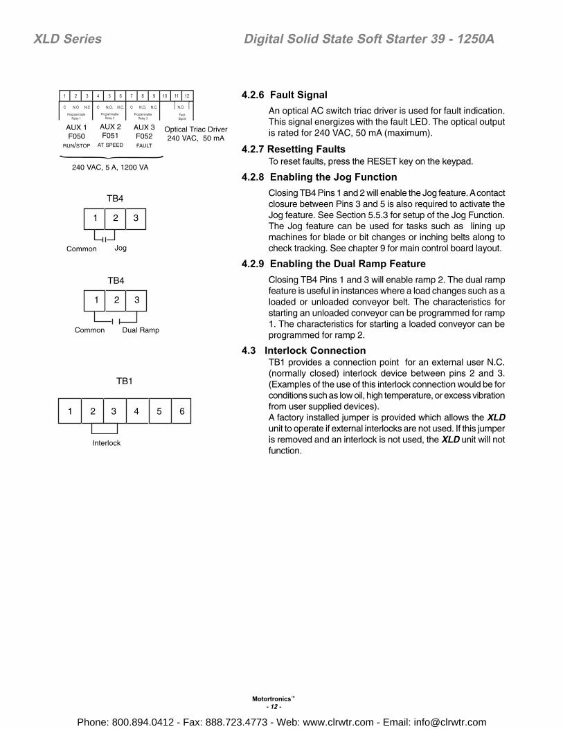
4.2.6 Fault SignalAn optical AC switch triac driver is used for fault indication.This signal energizes with the fault LED. The optical outputis rated for 240 VAC, 50 mA (maximum).
4.2.7 Resetting FaultsTo reset faults, press the RESET key on the keypad.
4.2.8 Enabling the Jog FunctionClosing TB4 Pins 1 and 2 will enable the Jog feature. A contactclosure between Pins 3 and 5 is also required to activate theJog feature. See Section 5.5.3 for setup of the Jog Function.The Jog feature can be used for tasks such as lining upmachines for blade or bit changes or inching belts along tocheck tracking. See chapter 9 for main control board layout.
4.2.9 Enabling the Dual Ramp FeatureClosing TB4 Pins 1 and 3 will enable ramp 2. The dual rampfeature is useful in instances where a load changes such as aloaded or unloaded conveyor belt. The characteristics forstarting an unloaded conveyor can be programmed for ramp1. The characteristics for starting a loaded conveyor can beprogrammed for ramp 2.
4.3 Interlock ConnectionTB1 provides a connection point for an external user N.C.(normally closed) interlock device between pins 2 and 3.(Examples of the use of this interlock connection would be forconditions such as low oil, high temperature, or excess vibrationfrom user supplied devices).A factory installed jumper is provided which allows the XLDunit to operate if external interlocks are not used. If this jumperis removed and an interlock is not used, the XLD unit will notfunction.
1 2 3
TB4
Common Dual Ramp
1 2 3
TB4
Common Jog
1 2 3 4 5 6
TB1
Interlock
AUX 1F050
RUN/STOP
AUX 2F051
AT SPEED
AUX 3F052FAULT
Optical Triac Driver240 VAC, 50 mA
240 VAC, 5 A, 1200 VA
Phone: 800.894.0412 - Fax: 888.723.4773 - Web: www.clrwtr.com - Email: [email protected]

Motortronics™
- 13 -
XLD Series Digital Solid State Soft Starter 39 - 1250A
5.1 IntroductionIt is best to operate the motor at its full load starting condition to achieve theproper time, torque and ramp settings. Initial factory settings are set toaccommodate general motor applications and provide basic motor protection.Advanced features must be enabled via programming. The only parameter thatMUST be set by the user is motor FLA (F001).
5.2 Digital InterfaceThe XLD Soft Starter includes an intuitive, digital keypad with eight LEDs,seven command keys, and an LED display with four alphanumeric digits.
Chapter 5 - Programming
Reset Clears the trip indicator and releases the trip relay.
Fn Enters or exits the program mode.
Up ArrowNavigates through the Status Display Mode, scrolls up through the listof functions, increases the value of an active (flashing) digit, and scrollsthrough the history of fault conditions.
Right ArrowEach keypress shifts the active (flashing) digit to the right one position,use to change function number or value.
Down ArrowNavigates through the Status Display Mode, scrolls down through thelist of functions, decreases the value of an active (flashing) digit, andscrolls through the history of fault conditions.
Left ArrowEach keypress shifts the flashing digit to the left one position, use tochange function number or value.
Read Enter Selects and stores the value of a function.
Power On Control power is present.
At SpeedMotor is at full speed and power.(The SCRs have phased fully on.)
Shorted SCRShorted SCR has been detected in the unit. Refer to section 8.2 forinstructions on checking SCRs.
Phase LossOne or more of the phase currents is low or has been lost while themotor was starting or running.
Over Temp Motor starter has tripped due to heat sink over temperature.
Over LoadStarter's motor overload has tripped. The overload must be resetbefore the fault can be cleared
Display 8888 4 digit 7 segment display
Two or more power poles are shorted and current is passing to themotor while in the off mode. For positive motor protection, an auxiliaryrelay shoul be be programmed for "Shunt Trip" and should beinterlocked with a shunt trip breaker or in-line contactor. (In the event ofa shunt trip, do not re-power the unit without repairing the power poles.)
Keys
YellowLEDs
Shunt Trip
Over Current
GreenLEDs
Over Current LED illuminates for two sets of fault conditions: overcurrent and short circuit.If unit experiences output current (of any phase) in excess of the valueprogrammed in F034 (over current trip %) for the time period specifiedin F035 (over current trip delay), this LED will illuminate and eitheroCA, oCC, or oCd will be displayed.If unit experiences a short circuit fault condition, the Over Current LEDilluminates and either SCA, SCC, or SCd will be displayed. This trip isfixed at 10 times the full load motor current and is not adjustable.
Phone: 800.894.0412 - Fax: 888.723.4773 - Web: www.clrwtr.com - Email: [email protected]

Motortronics™
- 14 -
XLD Series Digital Solid State Soft Starter 39 - 1250A
5.3 Display ModesThere are three modes of display: the Status Display mode, the Program mode,and the Fault mode.
5.3.1 Status Display ModeThe Status Display Mode displays three phase motor current information andthe thermal capacity remaining.Status mode:
• [0000.] The initial display on power up is four digits and the decimal. Thisindicates the motor current for Phase A of the motor.
• [0000] Scroll up to display four digits only (no decimal). This indicatesthe motor current for either Phase B or C. While viewing Phase A, pressthe UP arrow once to view Phase B or twice to view Phase C current.
• [H000] Scroll up to display the “H”. This indicates that this value is theremaining thermal capacity of the motor (as a percentage i.e. H070 =70% remaining thermal capacity)
Reading Phase Current and Thermal Capacity (See Example)[0120.] Indicates that Phase A isdrawing 120 amps.Press the UP arrow.[0121] Indicates that Phase B isdrawing 121 amps.Press the UP arrow.
NOTE: Decimal points are notpresent in the readoutsfor Phase B and Phase C.[0120] Indicates that Phase C isdrawing 120 amps.Press the UP arrow.[H051] Indicates that the motor has51% of its thermal capacityremaining.
5.3.2 Program ModeUse the Program Mode to view or change Function (Fn) settings.
To enter the Program Mode, press the [Fn] key once. The first time you enterProgram Mode after power has been cycled to the starter, the initial function[F001] should display with the selected digit flashing. If the XLD Soft Starter hasbeen programmed and power to the unit has not been cycled, the readout willdisplay the last function viewed or changed.
To change to a different function, use the arrow keys.
Program Mode:• [F001] The “F” indicates the programmable function.• [0000] This is the present setting of the applicable function. This display
may include decimals between digits depending on the function setting’srange and incremental step.
Display
Reading Phase Currentand
Thermal Capacity
0 120.
0 121
0 120
H05 1
Phase A
Phase B
Phase C
Remaining ThermalCapacity
Press
Phone: 800.894.0412 - Fax: 888.723.4773 - Web: www.clrwtr.com - Email: [email protected]
Motortronics™
- 15 -
XLD Series Digital Solid State Soft Starter 39 - 1250A
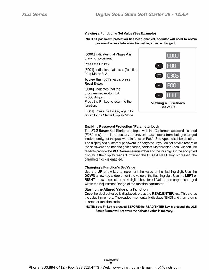
Viewing a Function’s Set Value (See Example) NOTE: If password protection has been enabled, operator will need to obtain
password access before function settings can be changed.
[0000.] Indicates that Phase A isdrawing no current.
Press the Fn key.
[F001] Indicates that this is (function001) Motor FLA.
To view the F001’s value, pressRead Enter.[0306] Indicates that theprogrammed motor FLAis 306 Amps.Press the Fn key to return to thefunction.
[F001] Press the Fn key again toreturn to the Status Display Mode.
Enabling Password Protection / Parameter LockThe XLD Series Soft Starter is shipped with the Customer password disabled(F060 = 0). If it is necessary to prevent parameters from being changedinadvertently, set the password in function F060. See Appendix 4 for details.The display of a customer password is encrypted. If you do not have a record ofthe password and need to gain access, contact Motortronics Tech Support. Beready to provide the XLD Series serial number and the four digits in the encrypteddisplay. If the display reads “Err” when the READ/ENTER key is pressed, theparameter lock is enabled.
Changing a Function’s Set ValueUse the UP arrow key to increment the value of the flashing digit. Use theDOWN arrow key to decrement the value of the flashing digit. Use the LEFT orRIGHT arrow to select the next digit to be altered. Values can only be changedwithin the Adjustment Range of the function parameter.
Storing the Altered Value of a FunctionOnce the desired value is displayed, press the READ/ENTER key. This storesthe value in memory. The readout momentarily displays [ END] and then returnsto another function code.
NOTE: If the Fn key is pressed BEFORE the READ/ENTER key is pressed, the XLDSeries Starter will not store the selected value in memory.
0000.
F00 1
0306
F00 1
0000.
Viewing a Function’sSet Value
Phone: 800.894.0412 - Fax: 888.723.4773 - Web: www.clrwtr.com - Email: [email protected]

™
- 16 -
XLD Series Digital Solid State Soft Starter 39 - 1250A
Setting Motor FLA and Overload Class During Start (See Example)
5.3.3 Fault ModeThe Fault Display Mode provides information to the operator when a fault occursor when the operator wishes to review fault history. Refer to Section 7 for details.Fault codes are three-digits in length and are displayed in alpha characters.The first and second characters (reading left to right) are the initials for theapplicable English-language fault name. The third or right-most character canbe either A, C, or D to denote when the fault occurred. A denotes Acceleration.C denotes Constant speed. D denotes Decel.Reading Fault Code (See Example)[ PLC.] Indicates a Phase Loss fault wasdetected while at Constant Speed. Thedecimal point (to the right of the C)denotes that this is the most recent faultcondition.Once a fault condition has been corrected, pressing the Reset key will returnthe readout to the Status Display mode. Fault History can be accessed during afault condition. While the current fault number is being displayed, use the Upand Down Arrow keys to scroll through the Fault History. Access Fault Historyvia Functions F075 through F083.
PLC.
Reading Fault Code
SettingOL Class
During Start
SettingmFLA
During Start
Phone: 800.894.0412 - Fax: 888.723.4773 - Web: www.clrwtr.com - Email: [email protected]
Motortronics™
- 17 -
XLD Series Digital Solid State Soft Starter 39 - 1250A
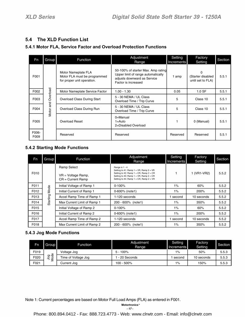
5.4 The XLD Function List5.4.1 Motor FLA, Service Factor and Overload Protection Functions
5.4.2 Starting Mode Functions
5.4.3 Jog Mode Functions
Note 1: Current percentages are based on Motor Full Load Amps (FLA) as entered in F001.
Fn Group FunctionAdjustment
RangeSetting
IncrementsFactorySetting
Section
F001Motor Nameplate FLAMotor FLA must be programmedfor proper unit operation.
50-100% of starter Max. Amp ratingUpper limit of range automaticallyadjusts downward as ServiceFactor is increased
1 amp0
(Starter disableduntil set to FLA)
5.5.1
F002 Motor Nameplate Service Factor 1.00 - 1.30 0.05 1.0 SF 5.5.1
F003 Overload Class During Start5 - 30 NEMA / UL ClassOverload Time / Trip Curve
5 Class 10 5.5.1
F004 Overload Class During Run5 - 30 NEMA / UL ClassOverload Time / Trip Curve
5 Class 10 5.5.1
F005 Overload Reset0=Manual1=Auto2=Disabled Overload
1 0 (Manual) 5.5.1
5.5.1F006-F009
Reserved Reserved Reserved Reserved
Mot
oran
dO
verlo
ad
Fn Group FunctionAdjustment
RangeSetting
IncrementsFactorySetting
Section
F010
Ramp Select
VR = Voltage Ramp,CR = Current Ramp
Range is 1 - 4Setting to #1: Ramp 1 = VR, Ramp 2 = VRSetting to #2: Ramp 1 = CR, Ramp 2 = CRSetting to #3: Ramp 1 = VR, Ramp 2 = CRSetting to #4: Ramp 1 = CR, Ramp 2 = VR
1 1 (VR1-VR2) 5.5.2
F011 Initial Voltage of Ramp 1 0-100% 1% 60% 5.5.2
F012 Initial Current of Ramp 1 0-600% (note1) 1% 200% 5.5.2
F013 Accel Ramp Time of Ramp 1 1-120 seconds 1 second 10 seconds 5.5.2
F014 Max Current Limit of Ramp 1 200 - 600% (note1) 1% 350% 5.5.2
F015 Initial Voltage of Ramp 2 0-100% 1% 60% 5.5.2
F016 Initial Current of Ramp 2 0-600% (note1) 1% 200% 5.5.2
F017 Accel Ramp Time of Ramp 2 1-120 seconds 1 second 10 seconds 5.5.2
F018 Max Current Limit of Ramp 2 200 - 600% (note1) 1% 350% 5.5.2
Sta
rtin
gM
ode
Fn Group FunctionAdjustment
RangeSetting
IncrementsFactorySetting
Section
F019 Voltage Jog 5 - 100% 1% 50% 5.5.3
F020 Time of Voltage Jog 1 - 20 Seconds 1 second 10 seconds 5.5.3
F021 Current Jog 100 - 500% 1% 150% 5.5.3
Jog
Mod
e
Phone: 800.894.0412 - Fax: 888.723.4773 - Web: www.clrwtr.com - Email: [email protected]
Motortronics™
- 18 -
XLD Series Digital Solid State Soft Starter 39 - 1250A
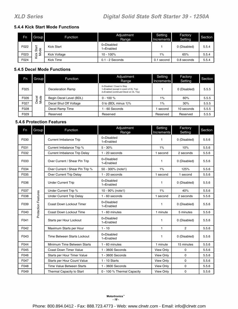
5.4.4 Kick Start Mode Functions
5.4.5 Decel Mode Functions
5.4.6 Protection Features
Fn Group FunctionAdjustment
RangeSetting
IncrementsFactorySetting
Section
F025 Deceleration Ramp0=Disabled / Coast to Stop1=Enabled (except in event of OL Trip)2=Enabled (continued Decel on OL Trip)
1 0 (Disabled) 5.5.5
F026 Begin Decel Level (BDL) 0 - 100 % 1% 60% 5.5.5
F027 Decel Shut Off Voltage 0 to (BDL minus 1)% 1% 30% 5.5.5
F028 Decel Ramp Time 1 - 60 Seconds 1 second 10 seconds 5.5.5
F029 Reserved Reserved Reserved Reserved 5.5.5
Dec
elM
ode
Fn Group FunctionAdjustment
RangeSetting
IncrementsFactorySetting
Section
F030 Current Imbalance Trip0=Disabled1=Enabled
1 0 (Disabled) 5.5.6
F031 Current Imbalance Trip % 5 - 30% 1% 10% 5.5.6
F032 Current Imbalance Trip Delay 1 - 20 seconds 1 second 2 seconds 5.5.6
F033 Over Current / Shear Pin Trip0=Disabled1=Enabled
1 0 (Disabled) 5.5.6
F034 Over Current / Shear Pin Trip % 50 - 300% (note1) 1% 125% 5.5.6
F035 Over Current Trip Delay 1 - 20 seconds 1 second 1 second 5.5.6
F036 Under Current Trip0=Disabled1=Enabled
1 0 (Disabled) 5.5.6
F037 Under Current Trip % 10 - 90% (note1) 1% 40% 5.5.6
F038 Under Current Trip Delay 1 - 60 seconds 1 second 2 seconds 5.5.6
F039 Coast Down Lockout Timer0=Disabled1=Enabled
1 0 (Disabled) 5.5.6
F040 Coast Down Lockout Time 1 - 60 minutes 1 minute 5 minutes 5.5.6
F041 Starts per Hour Lockout0=Disabled1=Enabled
1 0 (Disabled) 5.5.6
F042 Maximum Starts per Hour 1 - 10 1 2 5.5.6
F043 Time Between Starts Lockout0=Disabled1=Enabled
1 0 (Disabled) 5.5.6
F044 Minimum Time Between Starts 1 - 60 minutes 1 minute 15 minutes 5.5.6
F045 Coast Down Timer Value 1 - 3600 Seconds View Only 0 5.5.6
F046 Starts per Hour Timer Value 1 - 3600 Seconds View Only 0 5.5.6
F047 Starts per Hour Count Value 1 - 10 Starts View Only 0 5.5.6
F048 Time Value Between Starts 1 - 3600 Seconds View Only 0 5.5.6
F049 Thermal Capacity to Start 0 - 100 % Thermal Capacity View Only 0 5.5.6
Pro
tect
ion
Fea
ture
sFn Group Function
AdjustmentRange
SettingIncrements
FactorySetting
Section
F022 Kick Start0=Disabled1=Enabled
1 0 (Disabled) 5.5.4
F023 Kick Voltage 10 - 100% 1% 65% 5.5.4
F024 Kick Time 0.1 - 2 Seconds 0.1 second 0.8 seconds 5.5.4
Kic
kS
tart
Mod
e
Phone: 800.894.0412 - Fax: 888.723.4773 - Web: www.clrwtr.com - Email: [email protected]

Motortronics™
- 19 -
XLD Series Digital Solid State Soft Starter 39 - 1250A
5.4.7 Relays
Note 2: Auxiliary relays can be programmed for any of the following operations.# 1 - Run / Stop # 7 - Shunt Trip # 13 - Under Current Trip# 2 - At Speed / Stop # 8 - OL Trip # 14 - Any Trip (# 5 - #13)# 3 - At Speed / End of Decel # 9 - OT Trip # 15 - Coastdown Time# 4 - Start / End of Decel # 10 - Short Circuit Trip # 16 - Starts Per Hour# 5 - Short SCR Trip # 11 - Current Imbalance Trip # 17 - Time Between Starts# 6 - Phase Loss Trip # 12 - Over Current Trip # 18 - Any Lockout (#15 -17)
5.4.8 Communications
5.4.9 System Settings
Fn Group FunctionAdjustment
RangeSetting
IncrementsFactorySetting
Section
F050 Aux Relay 1 setting Operation # 1 - 18 (note2) 1 1 5.5.7
F051 Aux Relay 2 setting Operation # 1 - 18 1 2 5.5.7
F052 Aux Relay 3 setting Operation # 1 - 18 1 14 5.5.7
5.5.7F053-F054
ReservedReserved Reserved Reserved
Rel
ays
Fn Group FunctionAdjustment
RangeSetting
IncrementsDefaultSetting
Section
F055 Communications0=Disabled1=Enabled
1 0 5.5.8
F056 Modbus Address 1 - 247 1 1 5.5.8
F057 Baud Rate 4.8 - 19.2 KB 4.8 KB 4.8 KB 5.5.8
F058 Remote Starter Control0 = Disabled1 = Enabled
1 0 5.5.8
F059 Reserved Reserved Reserved Reserved 5.5.8
Com
mun
icat
ions
Fn Group FunctionAdjustment
RangeSetting
IncrementsFactorySetting
Section
F060Parameter Lock/User Password
Range is 0 - 9990 = DisabledAny Other Number = PasswordProtected
1 0 (Disabled) 5.5.9
F061 Reset Factory Default Settings
Range is 0 - 20=Disabled1=Clear Thermal Register andLockout Timers2 = Reset to Factory DefaultSettings
1 0 5.5.9
F062-F064
Reserved Reserved Reserved Reserved 5.5.9
F065 Year 2000 - 2047 1 Year Date of Mfg. 5.5.9
F066 Month 1 - 12 1 Month Date of Mfg. 5.5.9
F067 Day 1 - 31 1 Day Date of Mfg. 5.5.9
F068 Hour 0 - 23 1 Hour Date of Mfg. 5.5.9
F069 Minute 0 - 59 1 Minute Date of Mfg. 5.5.9
F070 Second 0 - 59 1 Second Date of Mfg. 5.5.9
F071 Revision # - View Only Factory Setting 5.5.9
F072-F074
Reserved Reserved Reserved Reserved 5.5.9
Sys
tem
Set
tings
Phone: 800.894.0412 - Fax: 888.723.4773 - Web: www.clrwtr.com - Email: [email protected]
Motortronics™
- 20 -
XLD Series Digital Solid State Soft Starter 39 - 1250A
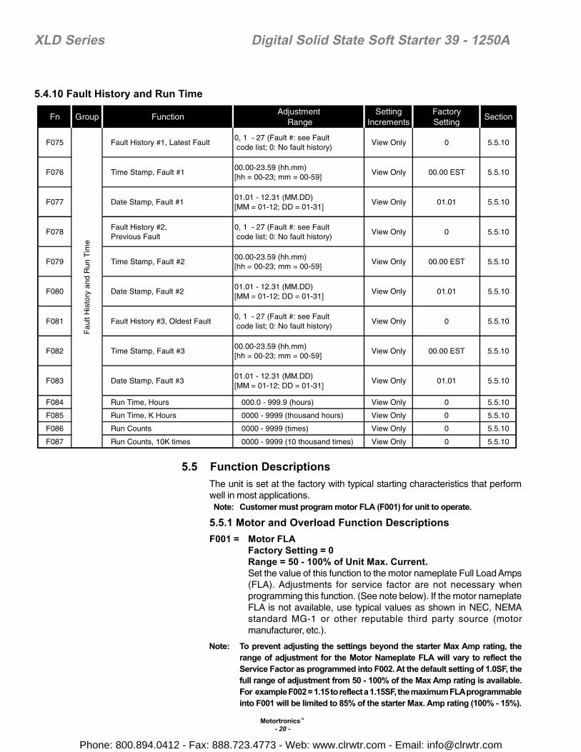
5.4.10 Fault History and Run Time
5.5 Function DescriptionsThe unit is set at the factory with typical starting characteristics that performwell in most applications.
Note: Customer must program motor FLA (F001) for unit to operate.
5.5.1 Motor and Overload Function DescriptionsF001 = Motor FLA
Factory Setting = 0Range = 50 - 100% of Unit Max. Current.Set the value of this function to the motor nameplate Full Load Amps(FLA). Adjustments for service factor are not necessary whenprogramming this function. (See note below). If the motor nameplateFLA is not available, use typical values as shown in NEC, NEMAstandard MG-1 or other reputable third party source (motormanufacturer, etc.).
Note: To prevent adjusting the settings beyond the starter Max Amp rating, therange of adjustment for the Motor Nameplate FLA will vary to reflect theService Factor as programmed into F002. At the default setting of 1.0SF, thefull range of adjustment from 50 - 100% of the Max Amp rating is available.For example F002 = 1.15 to reflect a 1.15SF, the maximum FLA programmableinto F001 will be limited to 85% of the starter Max. Amp rating (100% - 15%).
Fn Group FunctionAdjustment
RangeSetting
IncrementsFactorySetting
Section
F075 Fault History #1, Latest Fault0, 1 - 27 (Fault #: see Faultcode list; 0: No fault history)
View Only 0 5.5.10
F076 Time Stamp, Fault #100.00-23.59 (hh.mm)[hh = 00-23; mm = 00-59]
View Only 00.00 EST 5.5.10
F077 Date Stamp, Fault #101.01 - 12.31 (MM.DD)[MM = 01-12; DD = 01-31]
View Only 01.01 5.5.10
F078Fault History #2,Previous Fault
0, 1 - 27 (Fault #: see Faultcode list; 0: No fault history)
View Only 0 5.5.10
F079 Time Stamp, Fault #200.00-23.59 (hh.mm)[hh = 00-23; mm = 00-59]
View Only 00.00 EST 5.5.10
F080 Date Stamp, Fault #201.01 - 12.31 (MM.DD)[MM = 01-12; DD = 01-31]
View Only 01.01 5.5.10
F081 Fault History #3, Oldest Fault0, 1 - 27 (Fault #: see Faultcode list; 0: No fault history)
View Only 0 5.5.10
F082 Time Stamp, Fault #300.00-23.59 (hh.mm)[hh = 00-23; mm = 00-59]
View Only 00.00 EST 5.5.10
F083 Date Stamp, Fault #301.01 - 12.31 (MM.DD)[MM = 01-12; DD = 01-31]
View Only 01.01 5.5.10
F084 Run Time, Hours 000.0 - 999.9 (hours) View Only 0 5.5.10
F085 Run Time, K Hours 0000 - 9999 (thousand hours) View Only 0 5.5.10
F086 Run Counts 0000 - 9999 (times) View Only 0 5.5.10
F087 Run Counts, 10K times 0000 - 9999 (10 thousand times) View Only 0 5.5.10
Fau
ltH
isto
ryan
dR
unT
ime
Phone: 800.894.0412 - Fax: 888.723.4773 - Web: www.clrwtr.com - Email: [email protected]

Motortronics™
- 21 -
XLD Series Digital Solid State Soft Starter 39 - 1250A
F002 = Service FactorFactory Setting = 1.0 S.F.Range = 1.00 - 1.30Set value according to the Service Factor (SF) data provided on themotor’s nameplate. This value affects several protection features so itmust be accurate. Setting the SF too high may result in motor damagein overload conditions. Setting SF too low may cause nuisance trips.
F003 = Overload Class During StartFactory Setting = 10 (Class 10)Range = 5 - 30 NEMA / UL ClassSet value to the motor protection overload class required for theapplication. It is recommended that you try the factory setting first. (Ifpossible, keep values for F003 and F004 the same.) Increase F003above F004 only if nuisance tripping occurs during start. See Section3.2 for details on trip curves.
F004 = Overload Class During RunFactory Setting = 10 (Class 10)Range = 5 - 30 NEMA / UL ClassSet value according to the instructions provided by your motor /equipment manufacturer. This trip curve will not be enabled until themotor has reached full speed.
F005 = Overload ResetFactory Setting = 0 (Manual)Range = 0 - 2Set value to determine starter behavior after an overload conditionhas cleared.When set to 0 = Manual, the operator must press the Reset keybefore restarting the motor. Once the motor windings have cooledsufficiently AND the Reset key is pressed, the unit will accept a restartcommand.
When set to 1 = Automatic mode, and once sufficient time has elapsedallowing motor windings to cool, the motor will be restarted upon astart command.WARNING: Setting F005 = 1 (Automatic) may presentsignificant operational risk.When set to 2 = Disabled Overload, a separate external thermaloverload protection device must be in the circuit.
F006 - F009 = Reserved
Phone: 800.894.0412 - Fax: 888.723.4773 - Web: www.clrwtr.com - Email: [email protected]
Motortronics™
- 22 -
XLD Series Digital Solid State Soft Starter 39 - 1250A
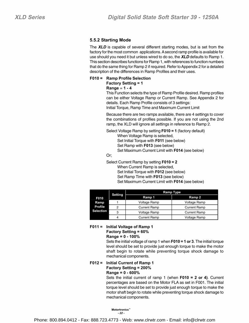
5.5.2 Starting ModeThe XLD is capable of several different starting modes, but is set from thefactory for the most common applications. A second ramp profile is available foruse should you need it but unless wired to do so, the XLD defaults to Ramp 1.This section describes functions for Ramp 1, with references to function numbersthat do the same thing for Ramp 2 if required. Refer to Appendix 2 for a detaileddescription of the differences in Ramp Profiles and their uses.
F010 = Ramp Profile SelectionFactory Setting = 1Range = 1 - 4This Function selects the type of Ramp Profile desired. Ramp profilescan be either Voltage Ramp or Current Ramp. See Appendix 2 fordetails. Each Ramp Profile consists of 3 settings:Initial Torque, Ramp Time and Maximum Current Limit
Because there are two ramps available, there are 4 settings to coverthe combinations of profiles possible. If you are not using the 2ndramp, the XLD will ignore all settings in reference to Ramp 2.
Select Voltage Ramp by setting F010 = 1 (factory default)When Voltage Ramp is selected,Set Initial Torque with F011 (see below)Set Ramp with F013 (see below)Set Maximum Current Limit with F014 (see below)
Or;
Select Current Ramp by setting F010 = 2When Current Ramp is selected,Set Initial Torque with F012 (see below)Set Ramp Time with F013 (see below)Set Maximum Current Limit with F014 (see below)
Ramp 1 Ramp 21 Voltage Ramp Voltage Ramp
2 Current Ramp Current Ramp
3 Voltage Ramp Current Ramp
4 Current Ramp Voltage Ramp
Ramp TypeSetting
F010RampProfile
Selection
F011 = Initial Voltage of Ramp 1Factory Setting = 60%Range = 0 - 100%Sets the initial voltage of ramp 1 when F010 = 1 or 3. The initial torquelevel should be set to provide just enough torque to make the motorshaft begin to rotate while preventing torque shock damage tomechanical components.
F012 = Initial Current of Ramp 1Factory Setting = 200%Range = 0 - 600%Sets the initial current of ramp 1 (when F010 = 2 or 4). Currentpercentages are based on the Motor FLA as set in F001. The initialtorque level should be set to provide just enough torque to make themotor shaft begin to rotate while preventing torque shock damage tomechanical components.
Phone: 800.894.0412 - Fax: 888.723.4773 - Web: www.clrwtr.com - Email: [email protected]

Motortronics™
- 23 -
XLD Series Digital Solid State Soft Starter 39 - 1250A
F013 = Accel Ramp Time of Ramp 1Factory Setting = 10 secondsRange = 1 - 120 secondsSets the time between the initial torque (set with F011 or F012) andeither the Max Current Limit (set with F014) or full output voltage. Settime to enable soft starts without stalls. Also consider your motor’sapplication. For example, centrifugal pumps may require a shorterramp time.
Note: Ramp time is affected by the following conditions:1. Current limit will extend the ramp time if the motor does not reach
full speed while in current limit mode.2. Anti-oscillation circuit will shorten the ramp time if the motor reaches
full speed before end of ramp.
F014 = Max Current Limit of Ramp 1Factory Setting = 350%Range = 200 - 600%Sets the maximum motor current that the XLD Starter will allow duringramp 1. This limit applies to both voltage and current-type ramping.
Current will be limited to this setting until either the motor reaches fullspeed or the over load protection feature trips (F003). Currentpercentages are based on the Motor FLA as programmed in F001.Once the motor has reached full speed, the current limit feature isinactive.
For Ramp 2 (user-optional ramp)This ramp is selected by closing the input on Terminals TB4 - Pins 1and 3. If this input is left open, the XLD will respond only to ramp 1settings as listed above. Since ramp 2 is always used in combinationwith ramp 1, different combinations of ramp profiles can be selectedin F010. Refer to Appendix 1 for additional information.
F015 = Initial Voltage of Ramp 2Factory Setting = 60%Range = 0 - 100%Sets the initial voltage of ramp 2 when F010 = 1 or 4. The initial torquelevel should be set to provide just enough torque to make the motorshaft begin to rotate while preventing torque shock damage tomechanical components.
F016 = Initial Current of Ramp 2Factory Setting = 200%Range = 0 - 600%Sets the initial current of ramp 2 when F010 = 2 or 3. Currentpercentages are based on the Motor FLA as programmed in F001.The initial torque level should be set to provide just enough torque tomake the motor shaft begin to rotate while preventing torque shockdamage to mechanical components.
F017 = Accel Ramp Time of Ramp 2Factory Setting = 10 secondsRange = 1 - 120 secondsSets the time between the initial torque (set with F015 or F016) andeither the Max Current Limit (set with F014) or full output voltage. Settime to enable soft starts without stalls. Also consider your motor’sapplication. For example, centrifugal pumps may require a shortertime. See notes under F013 for more details.
Phone: 800.894.0412 - Fax: 888.723.4773 - Web: www.clrwtr.com - Email: [email protected]
Motortronics™
- 24 -
XLD Series Digital Solid State Soft Starter 39 - 1250A
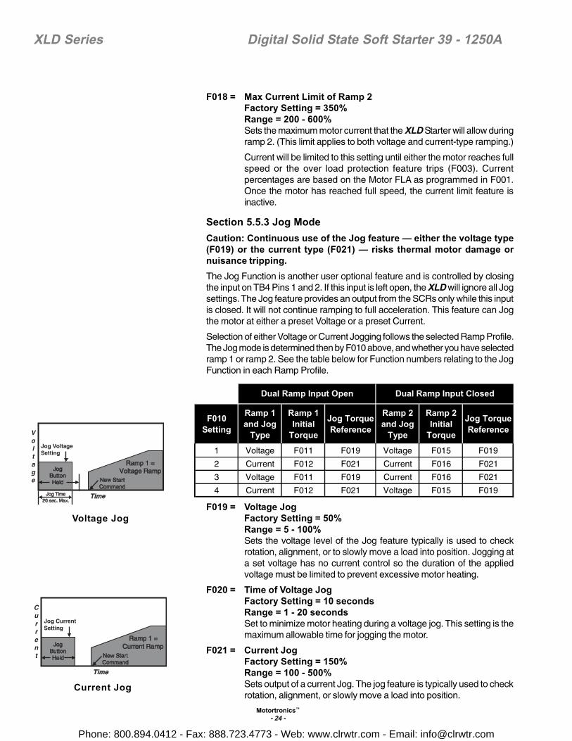
F018 = Max Current Limit of Ramp 2Factory Setting = 350%Range = 200 - 600%Sets the maximum motor current that the XLD Starter will allow duringramp 2. (This limit applies to both voltage and current-type ramping.)
Current will be limited to this setting until either the motor reaches fullspeed or the over load protection feature trips (F003). Currentpercentages are based on the Motor FLA as programmed in F001.Once the motor has reached full speed, the current limit feature isinactive.
Section 5.5.3 Jog ModeCaution: Continuous use of the Jog feature — either the voltage type(F019) or the current type (F021) — risks thermal motor damage ornuisance tripping.The Jog Function is another user optional feature and is controlled by closingthe input on TB4 Pins 1 and 2. If this input is left open, the XLD will ignore all Jogsettings. The Jog feature provides an output from the SCRs only while this inputis closed. It will not continue ramping to full acceleration. This feature can Jogthe motor at either a preset Voltage or a preset Current.
Selection of either Voltage or Current Jogging follows the selected Ramp Profile.The Jog mode is determined then by F010 above, and whether you have selectedramp 1 or ramp 2. See the table below for Function numbers relating to the JogFunction in each Ramp Profile.
F010Setting
Ramp 1and Jog
Type
Ramp 1Initial
Torque
Jog TorqueReference
Ramp 2and Jog
Type
Ramp 2Initial
Torque
Jog TorqueReference
1 Voltage F011 F019 Voltage F015 F019
2 Current F012 F021 Current F016 F021
3 Voltage F011 F019 Current F016 F021
4 Current F012 F021 Voltage F015 F019
Dual Ramp Input Open Dual Ramp Input Closed
F019 = Voltage JogFactory Setting = 50%Range = 5 - 100%Sets the voltage level of the Jog feature typically is used to checkrotation, alignment, or to slowly move a load into position. Jogging ata set voltage has no current control so the duration of the appliedvoltage must be limited to prevent excessive motor heating.
F020 = Time of Voltage JogFactory Setting = 10 secondsRange = 1 - 20 secondsSet to minimize motor heating during a voltage jog. This setting is themaximum allowable time for jogging the motor.
F021 = Current JogFactory Setting = 150%Range = 100 - 500%Sets output of a current Jog. The jog feature is typically used to checkrotation, alignment, or slowly move a load into position.
Voltage Jog
Current Jog
Phone: 800.894.0412 - Fax: 888.723.4773 - Web: www.clrwtr.com - Email: [email protected]

Motortronics™
- 25 -
XLD Series Digital Solid State Soft Starter 39 - 1250A
5.5.4 Kick Start Mode Note: Do not use the Kick Start feature unless you determine that you need it.
Using this feature may eliminate many of the mechanical and electrical benefitsof using a Soft Starter.
F022 = Kick StartFactory Setting = 0 (Disabled)Range = 0 - 1Kick start applies a “pulse” of voltage to the motor to produce amomentary “kick” of high torque to break the motor load free fromhigh friction or frozen components. When F022 = 1, this voltage “pulse”begins the initial voltage applied in either F011 or F015. Voltage levelis adjusted by F023 and the time duration of the pulse is adjusted byF024.
F023 = Kick VoltageFactory Setting = 65%Range = 10 - 100%Sets the voltage level of the Kick Start feature. The setting of F023should be higher than F011 and F015 and high enough to provide abenefit in the worst starting condition.
F024 = Kick TimeFactory Setting = 0.8 secondsRange = 0.1 - 2 secondsSets the duration of time the Kick Start voltage is applied.
5.5.5 Decel ModeDeceleration is a feature of the XLD Soft Starter which slowly decreases theapplied voltage to the motor when a stop command is given resulting in a gentledecrease in motor torque. Deceleration provides a way to extend the stoppingtime so that abrupt stopping does not occur. Deceleration is useful with centrifugalpumps, material handlers, and conveyors where abrupt stopping could bedamaging to the equipment and/or load
Note: Decel is THE OPPOSITE of braking. Enabling the Decel feature will make themotor take LONGER to stop than if it were simply turned off.
See Appendix 2 at the end of this manual for detailed descriptions of typicalapplications for the Decel feature.
F025 = Deceleration RampFactory Setting = 0 (Disabled)Range = 0 - 2
When F025 = 0, the deceleration feature is disabled.
When F025 = 1, the deceleration feature is enabled AND the overloadprotection feature, set with F003 and F004, is enabled. Even whenthe stop command is received, the starter continues to apply decelvoltage. However, if an overload trip occurs, the starter stops applyingvoltage and the motor coasts to a stop to prevent additional motorheating and potential motor damage.
When F025 = 2, the deceleration feature is enabled and decelerationwill continue even when an overload condition trips.
WARNING: Setting F025 = 2 presents significant risk of over-heating themotor beyond its design limits which could result in motor damage andfire hazard. Do this only in circumstances where the potential formechanical damage outweighs the risk of motor damage.
Kick Start
Phone: 800.894.0412 - Fax: 888.723.4773 - Web: www.clrwtr.com - Email: [email protected]

Motortronics™
- 26 -
XLD Series Digital Solid State Soft Starter 39 - 1250A
F026 = Begin Decel Level (BDL)Factory Setting = 60%Range = 0 - 100% of line voltageUse to drop voltage to a level where there is a noticeable effect onmotor torque during decel mode.
F027 = Decel Shut Off VoltageFactory Setting = 30%Range = 0 to (BDL -1)%Sets the level where motor torque during decel is no longer effective.Always set this function lower than the setting of F026, Begin DecelLevel.
F028 = Decel Ramp TimeFactory Setting = 10 secondsRange = 1 - 60 secondsSets the maximum time for the deceleration ramp to go from the BeginDecel Level setting (F026) to the Decel Shut Off Voltage (F027). Sincemotor heating increases as voltage is lowered, the setting should notexceed the time necessary to achieve the deceleration effect.
F029 = Reserved
5.5.6 Protection Features
F030 = Current Imbalance TripFactory Setting = 0 (Disabled)Range = 0 - 1If F030 = 1 (Enabled), starter will trip when the output current betweenany two phases exceeds the amount set with F031 for the timespecified with F032.
F031 = Current Imbalance Trip %Factory Setting = 10%Range = 5 - 30%Use to set the trip level for current imbalance between any two phases.Percentage is based on FLA (F001 setting).
F032 = Current Imbalance Trip DelayFactory Setting = 2 secondsRange = 1 - 20 secondsProvides a time delay to prevent nuisance trips from short-durationtransients. Using default settings, if the difference in output currentbetween two phases exceeds 10% of FLA for more than 2 seconds,the starter will trip.
F033 = Over Current / Shear Pin TripFactory Setting = 0 (Disabled)Range = 0 - 1If F033 = 1 (Enabled), starter will trip when the output current of anyphase exceeds the amount set with F034 for the time specified withF035. Can be referred to as a “Shear Pin Trip” and can be used toprotect mechanical components from breaking due to jammed loads.
F034 = Over Current Trip %Factory Setting = 125%Range = 100 - 300%Use to set the trip level for an over current condition for any phase.Percentage is based on FLA (F001 setting).
Over Current Trip(F033 = 1)
Phone: 800.894.0412 - Fax: 888.723.4773 - Web: www.clrwtr.com - Email: [email protected]
Motortronics™
- 27 -
XLD Series Digital Solid State Soft Starter 39 - 1250A
F035 = Over Current Trip delayFactory Setting = 1 secondRange = 1 - 20 secondsProvides a time delay to prevent nuisance trips from short-durationtransients. Using default settings, if the output current of any phaseexceeds 125% of FLA for more than 1 second, the starter will trip.
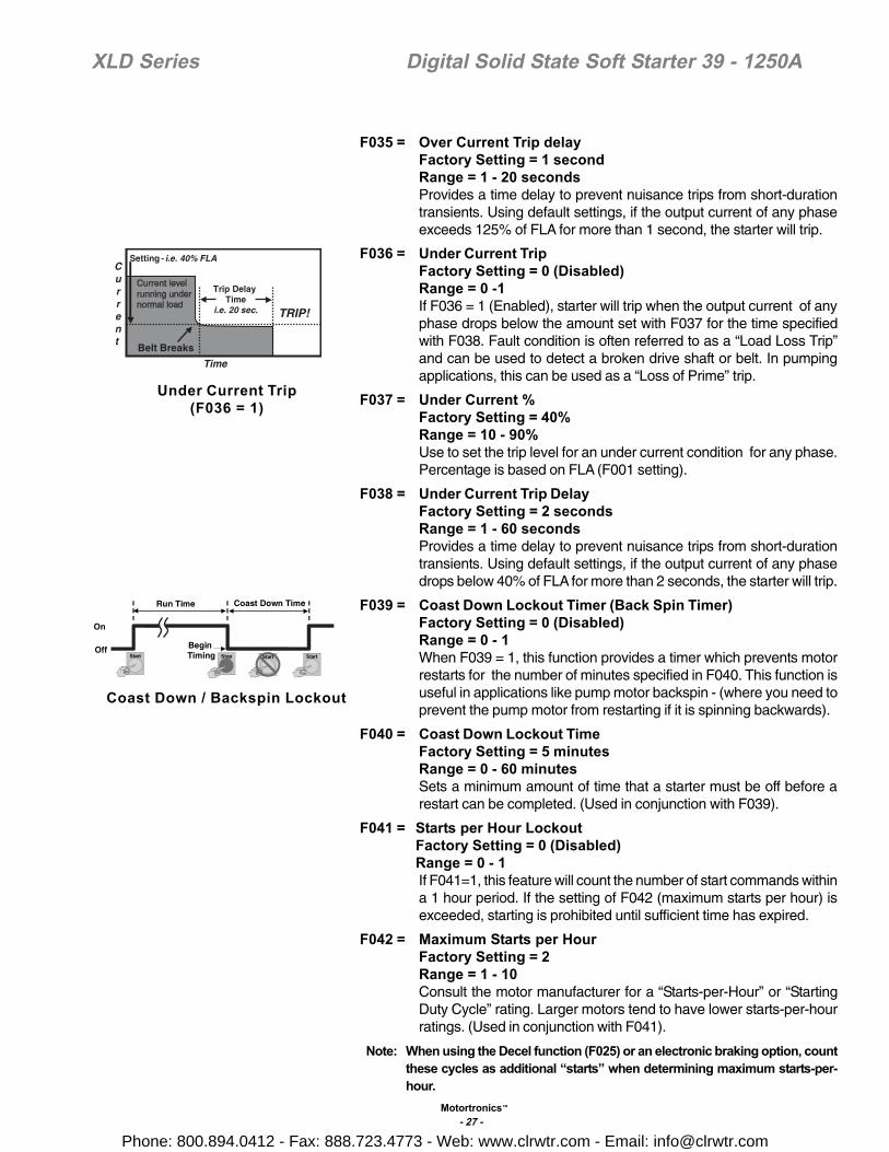
F036 = Under Current TripFactory Setting = 0 (Disabled)Range = 0 -1If F036 = 1 (Enabled), starter will trip when the output current of anyphase drops below the amount set with F037 for the time specifiedwith F038. Fault condition is often referred to as a “Load Loss Trip”and can be used to detect a broken drive shaft or belt. In pumpingapplications, this can be used as a “Loss of Prime” trip.
F037 = Under Current %Factory Setting = 40%Range = 10 - 90%Use to set the trip level for an under current condition for any phase.Percentage is based on FLA (F001 setting).
F038 = Under Current Trip DelayFactory Setting = 2 secondsRange = 1 - 60 secondsProvides a time delay to prevent nuisance trips from short-durationtransients. Using default settings, if the output current of any phasedrops below 40% of FLA for more than 2 seconds, the starter will trip.
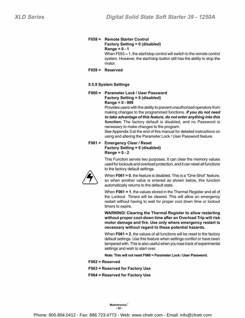
F039 = Coast Down Lockout Timer (Back Spin Timer)Factory Setting = 0 (Disabled)Range = 0 - 1When F039 = 1, this function provides a timer which prevents motorrestarts for the number of minutes specified in F040. This function isuseful in applications like pump motor backspin - (where you need toprevent the pump motor from restarting if it is spinning backwards).
F040 = Coast Down Lockout TimeFactory Setting = 5 minutesRange = 0 - 60 minutesSets a minimum amount of time that a starter must be off before arestart can be completed. (Used in conjunction with F039).
F041 = Starts per Hour LockoutFactory Setting = 0 (Disabled)Range = 0 - 1If F041=1, this feature will count the number of start commands withina 1 hour period. If the setting of F042 (maximum starts per hour) isexceeded, starting is prohibited until sufficient time has expired.
F042 = Maximum Starts per HourFactory Setting = 2Range = 1 - 10Consult the motor manufacturer for a “Starts-per-Hour” or “StartingDuty Cycle” rating. Larger motors tend to have lower starts-per-hourratings. (Used in conjunction with F041).
Note: When using the Decel function (F025) or an electronic braking option, countthese cycles as additional “starts” when determining maximum starts-per-hour.
Under Current Trip(F036 = 1)
Coast Down / Backspin Lockout
Phone: 800.894.0412 - Fax: 888.723.4773 - Web: www.clrwtr.com - Email: [email protected]

Motortronics™
- 28 -
XLD Series Digital Solid State Soft Starter 39 - 1250A
F043 = Time Between Starts LockoutFactory Setting = 0 (Disabled)Range = 0 - 1If F043= 1, the motor cannot be started within the time specified inF044. Time between starts is calculated from the time of the first startcommand to the next regardless of run time. (Used in conjunctionwith F041).
Time Between Starts Lockout
F044 = Minimum Time Between StartsFactory Setting = 15 minutesRange = 1 - 60 minutesIf F043 = 1 and F044 = 15, motor will not start within 15 minutes of firststart.
F045 = Coast Down Timer ValueFactory Setting = Not ApplicableRange = 1 - 3600 SecondsDisplay for information only; value cannot be altered by the user.Readout only for user’s viewing of remaining time value of the CoastDown Lockout Timer.
F046 = Starts per Hour Timer ValueFactory Setting = Not ApplicableRange = 1 - 3600 SecondsDisplay for information only; value cannot be altered by the user.
Readout only for user’s viewing of remaining time value of Starts-per-Hour Lockout Timer.
F047 = Starts per HourFactory Setting = Not ApplicableRange = 1 - 10 StartsDisplay for information only; value cannot be altered by the user.Readout only for user’s viewing of the accumulated Starts-per-Hourvalue used in the Lockout function.
F048 = Time Value Between StartsFactory Setting = Not ApplicableRange = 1 - 3600 SecondsDisplay for information only; value cannot be altered by the user.Readout only for user’s viewing of remaining time value of MinimumTime Between Starts Timer.
Phone: 800.894.0412 - Fax: 888.723.4773 - Web: www.clrwtr.com - Email: [email protected]

Motortronics™
- 29 -
XLD Series Digital Solid State Soft Starter 39 - 1250A
F049 = Thermal Capacity to StartFactory Setting = Not ApplicableRange = 0 - 100 % Thermal CapacityDisplay for information only; value cannot be altered by the user.Readout only for user’s viewing of the motor Thermal Capacitypercentage required to allow a Reset after an Overload Trip. Use thisfunction in conjunction with the Remaining Thermal Capacity to beable to predict when a restart will be allowed. This value is automaticallyupdated by the XLD whenever a successful start sequence has beenaccomplished. The XLD essentially “learns” how much ThermalCapacity is needed in the motor in order to successfully restart, andstores the information at this Function.
5.5.7 RelaysThere are three programmable relays (rated 240VAC, 5A, 1200 VA) on the XLDSeries. They can be programmed for change of state indication for any one ofthe 18 conditions identified in the chart to the left.
F050 = Aux Relay 1Factory Setting = 1 (Run / Stop)Range = 1 - 18 (See list.)Use to program the desired operation for Relay # 1.
F051 = Aux Relay 2Factory Setting = 2 (At Speed / Stop)Range = 1 - 18 (See list.)Use to program the desired operation for Relay # 2.
F052 = Aux Relay 3Factory Setting = 14 (Any Trip)Range = 1 - 18 (See list.)Use to program the desired operation for Relay # 3.
F053 - F054 = Reserved
5.5.8 CommunicationsThe XLD Soft Starter features built-in serial communications via RS-485hardware and Modbus RTU protocol software. The XLD Soft Starter is a “passive”communication device which responds and/or replies to the commands of “active”host devices such as personal computers, SCADA systems, PLCs with ASCIIports, DCS and other industrial systems.F055 = Communications
Factory Setting = 0 (Disabled) 1 (Enabled)Range = 0 - 1When F055 = 1, the XLD Soft Starter will communicate with remotemonitoring and control systems.
F056 = Baud RateFactory Setting = 9.6 KBRange = 4.8 to 19.2 KBSet value to either 4.8 KB, 9.6 KB, 14.4 KB or 19.2 KB and match thesetting of the host device.
F057 = Modbus AddressFactory Setting = 1Range = 1 - 247The Modbus communications protocol allows each node to have upto 247 connected devices but each must have a unique address. Twodevices with the same address will result in a communications error.
SettingProgrammableRelay SettingDescriptions
1 Run / Stop
2 At Speed / Stop
3 At Speed / End of Decel
4 Start / End of Decel
5 Short SCR Trip
6 Phase Loss Trip
7 Shunt Trip
8 Over Load Trip
9 Over Temperature Trip
10 Short Circuit Trip
11 Current Imbalance Trip
12 Over Current Trip
13 Under Current Trip
14 Any Trip (5 - 13)
15 Coastdown Time
16 Starts Per Hour
17 Time Between Starts
18 Any Lockout (15 - 17)
Phone: 800.894.0412 - Fax: 888.723.4773 - Web: www.clrwtr.com - Email: [email protected]
Motortronics™
- 30 -
XLD Series Digital Solid State Soft Starter 39 - 1250A
F058 = Remote Starter ControlFactory Setting = 0 (disabled)Range = 0 - 1When F055 = 1, the start/stop control will switch to the remote controlsystem. However, the start/stop button still has the ability to stop themotor.
F059 = Reserved
5.5.9 System Settings
F060 = Parameter Lock / User PasswordFactory Setting = 0 (disabled)Range = 0 - 999Provides users with the ability to prevent unauthorized operators frommaking changes to the programmed functions. If you do not needto take advantage of this feature, do not enter anything into thisfunction. The factory default is disabled, and no Password isnecessary to make changes to the program.See Appendix 3 at the end of this manual for detailed instructions onusing and altering the Parameter Lock / User Password feature.
F061 = Emergency Clear / ResetFactory Setting = 0 (disabled)Range = 0 - 2This Function serves two purposes. It can clear the memory valuesused for lockouts and overload protection, and it can reset all functionsto the factory default settings.
When F061 = 0, the feature is disabled. This is a “One-Shot” feature,so when another value is entered as shown below, this functionautomatically returns to the default state.
When F061 = 1, the values stored in the Thermal Register and all ofthe Lockout Timers will be cleared. This will allow an emergencyrestart without having to wait for proper cool down time or lockouttimers to expire.
WARNING! Clearing the Thermal Register to allow restartingwithout proper cool-down time after an Overload Trip will riskmotor damage and fire. Use only where emergency restart isnecessary without regard to these potential hazards.When F061 = 2, the values of all functions will be reset to the factorydefault settings. Use this feature when settings conflict or have beentampered with. This is also useful when you lose track of experimentalsettings and wish to start over.
Note: This will not reset F060 = Parameter Lock / User Password.
F062 = ReservedF063 = Reserved for Factory UseF064 = Reserved for Factory Use
Phone: 800.894.0412 - Fax: 888.723.4773 - Web: www.clrwtr.com - Email: [email protected]

Motortronics™
- 31 -
XLD Series Digital Solid State Soft Starter 39 - 1250A
5.5.9.a Real Time Clock SettingsFunctions F065 through F070 set the system real time clock. The time clock isprimarily used in date/time stamping Fault History. Time clock automaticallyadjusts for leap years. Time clock does not automatically adjust for daylightsavings time.F065 = Year
Factory Setting = Year of manufactureRange = 2000 to 2047
F066 = MonthFactory Setting = Month of manufactureRange = 1 - 12
F067 = DayFactory Setting = Day of manufactureRange = 1 - 31
F068 = HourFactory Setting = Actual (EST)Range = 0 - 23 (12:00 midnight is hour 0)
F069 = MinuteFactory Setting = Actual (EST)Range = 0 - 59
F070 = SecondFactory Setting = Actual (EST)Range = 0 - 59
F071 = Reserved for Factory UseF072 -F074 = Reserved
5.5.10 Fault History and Run TimeThe fault history will store the three last fault conditions plus the date and timethat each fault occurred.
F075 = Fault History # 1, Latest FaultFactory Setting = 0000Range = NADisplays 2-digit fault number. See Chapter 7.
F076 = Time Stamp, Fault # 1Factory Setting = 00.00Range = HH.MM where HH = 00 - 23 and MM = 00 - 59Displays time fault in F075 was detected.
F077 = Date Stamp, Fault # 1Factory Setting = 01.01Range = MM.DD where MM = 01 - 12 and DD = 01 - 31Displays date time fault in F075 was detected.
F078 = Fault History # 2, Previous FaultFactory Setting = 0000Range = NADisplays 2-digit fault number. See Chapter 7.
Phone: 800.894.0412 - Fax: 888.723.4773 - Web: www.clrwtr.com - Email: [email protected]

Motortronics™
- 32 -
XLD Series Digital Solid State Soft Starter 39 - 1250A
F079 = Time Stamp, Fault # 2Factory Setting = 00.00Range = HH.MM where HH = 00 - 23 and MM = 00 - 59Displays time fault in F078 was detected.
F080 = Date Stamp, Fault # 2Factory Setting = 01.01Range = MM.DD where MM = 01 - 12 and DD = 01 - 31Displays date time fault in F078 was detected.
F081 = Fault History # 3, Oldest FaultFactory Setting = 0000Range = NADisplays 2-digit fault number. See Chapter 7.
F082 = Time Stamp, Fault # 3Factory Setting = 00.00Range = HH.MM where HH = 00 - 23 and MM = 00 - 59Displays time fault in F081 was detected.
F083 = Date Stamp, Fault # 3Factory Setting = 01.01Range = MM.DD where MM = 01 - 12 and DD = 01 - 31Displays date time fault in F081 was detected.
Functions F084 through F087 display information from the Run Time/ Elapsed Time meter and Run-Cycle counter. Run time includes Accel,Run, Decel, and Jog operations.
F084 = Run Time, HoursFactory Setting = 0000Range = 000.9 - 999.9 hoursRun counts in excess of 999.9 are recorded in F085.
F085 = Run Time, K HoursFactory Setting = 0000Range = 0000 - 9999 K hours0001 in readout means a run time of 1,000 hours.
F086 = Run CountsFactory Setting = 0000Range = 0000 - 9999Run counts in excess of 9999 are recorded in F087.
F087 = Run Counts, 10K TimesFactory Setting = 0000Range = 0000 - 9999, 10 thousand times0001 in readout means a run count of 10,000 operations.
Phone: 800.894.0412 - Fax: 888.723.4773 - Web: www.clrwtr.com - Email: [email protected]

Motortronics™
- 33 -
XLD Series Digital Solid State Soft Starter 39 - 1250A
6.1 Quick StartYour new XLD Series Soft Starter is factory preset for a wide variety ofapplications and often can be used with minimal adjustment.
6.1.1. Three Step Process1. Connect L1, L2, and L3 to power lines and T1, T2, and T3 to motor.
2. Connect control wires and control power.
3. Program motor FLA (F001).
6.1.2 XLD Start-up Parameters and Factory DefaultsTry the initial presets first and then adjust or enable the more advanced featuresto meet your specific starting needs.
Chapter 6 - Start-up
TB1 Two-Wire Connection(alternate connection)
TB1 Three-Wire Connection
(See page 20 for more information)
AUX 1F050
RUN/STOP
AUX 2F051
AT SPEED
AUX 3F052FAULT
Optical Triac Driver240 VAC, 50 mA
240 VAC, 5 A, 1200 VA
FunctionNumber
FunctionName
FactorySetting Description
F001 Motor Nameplate FLA 0Starter disabledUnit must be set to actual motorFLA
F002 Motor Service Factor 1.0Motor Service Factorfrom motor nameplate
F003 Overload ProtectionDuring Start
10NEMA Overload Class(Class 10)
F004 Overload ProtectionDuring Run
10NEMA Overload Class(Class 10)
F005 Overload Reset 0 Manual Reset
F010 Ramp Profile 1
Ramp 1 is voltage rampwith current limit;Ramp 2 is voltage rampwith current limit
F011 Initial Torque 60 60 Percent
F013 Ramp Time 1010 second time durationfor Ramp 1
F014 Current Limit 350Maximum current limit of Ramp1 as a percentage (350%).
F015-F018 Ramp 2 60,200,10,350Inactive unless TB4 controlcircuit is wired
F019-F021 Jog 50,10,150Inactive unless TB4 controlcircuit is wired
F022-F049 All other protectionand control features
See Note Disabled
F050 Aux. Relay #1(TB2, terminals 1 - 3)
1 Run / Stop
F051 Aux. Relay #2(TB2, terminals 4 - 6)
2 At Speed / Stop
F052 Aux. Relay #3(TB2, terminals 7 - 9)
14 Any Fault
F060 Parameter Lock /User Password
0 User password disabled
F065-F070 All Time Values 0 Eastern Standard Time
F075-F083 Fault Histories Clear Entered upon occurrence
Phone: 800.894.0412 - Fax: 888.723.4773 - Web: www.clrwtr.com - Email: [email protected]
Motortronics™
- 34 -
XLD Series Digital Solid State Soft Starter 39 - 1250A
6.2 Start-up Check List•Supply voltage matches the rated supply voltage of the unit.•Horsepower and current ratings of the motor and unit match or the unit is higher rating.• Initial ramp time and torque adjustments have been checked.•Power lines are attached to the unit input terminals marked L1, L2 and L3.•Motor leads are connected to the lower terminals marked T1, T2, and T3.•Appropriate control power is applied and/or control connections have been made.• “Power on” light located on the front of the unit turns on when control power is applied.•Four seven-segment LED readouts are visible.•The motor’s FLA has been programmed in function F001.•The thermal overload is properly set. (Use F003 and F004 to set OL Class.)•The motor area and equipment are clear of people and parts before start-up.
6.3 Sequence of Operation• Apply three phase power to the unit. The motor should run only when the start command is applied.• Apply control power and check that the “Power On” LED comes on.• Verify that the motor’s FLA is correctly programmed (F001).• Apply the start command. The motor should begin to accelerate.• When the motor reaches full speed, the “At Speed” LED comes on.• If the motor decelerates, or stops, during the acceleration period,
hit the stop button immediately and open the disconnect line.
If the unit does not follow this operational sequence please refer to Chapter 8 -Troubleshooting.
Sequence of Operation
Phone: 800.894.0412 - Fax: 888.723.4773 - Web: www.clrwtr.com - Email: [email protected]

Motortronics™
- 35 -
XLD Series Digital Solid State Soft Starter 39 - 1250A
Chapter 7 - Fault Conditions7.1 Fault Codes and Numbers (in History)
A three-character fault code is displayed in the LED display at the time of thetrip event. For instance, if Function F003 (overload protection) is set too low forthe size of the load, the code “OLA” will be displayed. Its corresponding numberwill be entered into the fault history. In this case, the number 0010 will be availablefor display in the window of function F075 (Fault History). The time the fault wasdetected is available in Function F076. It is expressed as hh.mm. So if the“OLA” fault occurred at 10:00 am, F076 would display 10.00. The date the faultoccurred is available in Function F077. The date is expressed as mm.dd. So ifthe “OLA” fault occurred on March 1, F077 would display 03.01.If there are no fault conditions in history, the display in F075 would read 0000.
For detailed explanation of Fault Codes, Fault Numbers, Probable Cause andSolution, see Chapter 8 - Troubleshooting.
Over Current During Accel
(Current) Imbalance DuringAccel
Over Load During Accel
Fault Code Examples:
HistoryFault Number
(shown in F075,F078, F081)
Fault Code@ Trip/Event
LEDIndications Description
1 OCA Over Current Over Current During Acceleration
2 OCC Over Current Over Current During Constant Speed
3 Ocd Over Current Over Current During Decel (or Stop)
4 PLA Phase Loss Phase Loss During Acceleration
5 PLC Phase Loss Phase Loss During Constant Speed
6 PLd Phase Loss Phase Loss During Decel (or Stop)
7 OtA Over Temp Over Temperature During Acceleration
8 OtC Over Temp Over Temperature During Constant Speed
9 Otd Over Temp Over Temperature During Decel (or Stop)
10 OLA Over Load Over Load During Acceleration
11 OLC Over Load Over Load During Constant Speed
12 OLd Over Load Over Load During Decel (or Stop)
13 SSA Shorted SCR Shorted SCR During Acceleration
14 SSC Shorted SCR Shorted SCR During Constant Speed
15 SSd Shorted SCR Shorted SCR During Decel (or Stop)
16 St Shunt Trip Shunt Trip During Acceleration
17 St Shunt Trip Shunt Trip During Constant Speed
18 St Shunt Trip Shunt Trip During Decel (or Stop)
19 ibA NA Phase Imbalance Current During Acceleration
20 ibC NA Phase Imbalance During Constant Speed
21 ibd NA Phase Imbalance During Decel (or Stop)
22 UCA NA Under Current During Acceleration
23 UCC NA Under Current During Constant Speed
24 UCd NA Under Current During Decel (or Stop)
25 SCA Over Current Short Circuit During Acceleration
26 SCC Over Current Short Circuit During Constant Speed
27 SCd Over Current Short Circuit During Decel (or Stop)
Phone: 800.894.0412 - Fax: 888.723.4773 - Web: www.clrwtr.com - Email: [email protected]

Motortronics™
- 36 -
XLD Series Digital Solid State Soft Starter 39 - 1250A
Chapter 8 - Troubleshooting8.1 Failure Analysis
FaultCode / # LED Fault # or
Code Description Explanation : Probable Cause : Solution Fn ListRef
OCA# 1
Over Current during Acceleration/ Start mode
Over Current Trip based on user settings. This protection is not enableduntil the very end of the Accel ramp. OCA Trip may indicate a StalledMotor condition. Observe motor acceleration and correct problem orincrease the trip settings.
OCC# 2
Over Current duringConstant Speed / Run mode
OCd# 3
Over Current during Deceleration/ Stop mode
PLA# 4
Phase Loss during Acceleration /Start mode
Current in at least one phase is less than 20% of unit rating. Thisprotection is disabled for the first 3 seconds of ramp time to allow currentto increase.Usually indicates miswiring of a Bypass Contactor. (Power is not passingthrough current transformer.) Refer to Appendix 4 for correct wiring.
PLC# 5
Phase Loss duringConstant Speed / Run mode
PLd# 6
Phase Loss during Deceleration /Stop mode
OtA# 7
Over temperature duringAcceleration / Start mode.
OtC# 8
Over temperature duringConstant Speed / Run mode.
Otd# 9
Over temperature duringDeceleration / Stop mode
OLA# 10
Motor thermal Overload duringAcceleration / Start mode
I2T thermal overload has tripped during acceleration/start mode. ThermalCapacity as determined by thermal register is zero. Probable cause:1) Excessive load on motor. Change operating conditions or user largermotor.2) Inadequate acceleration settings. Increase current limit or shortenramp time. Refer to section 5.5.2 and Appendix #1.3) High friction starting conditions. Try using Accel Kick feature, seesection 5.5.44) Overload Trip class during Start (F003) is set too low to allowacceleration. Change settings to next higher trip class (consult motormanufacturer)
F001- F003
OLC# 11
Motor thermal Overload duringConstant Speed / Run mode.
I2T thermal overload has tripped during acceleration/start mode. ThermalCapacity as determined by thermal register is zero. Probable cause:1) Excessive load on motor. Change operating conditions or user largermotor.2) Inadequate acceleration settings. Increase current limit or shortenramp time. Refer to section 5.5.2 and Appendix #1.3) Motor and/or load bearings are failing. Check mechanical systems andrepair.4) Overload Trip Class during Run (F004) is possibly set too low. Changesettings to next higher trip class only if motor is rated.
F001- F002,F004
Over Current Trip based on user settings: Probable cause:1) "Shear Pin" trip to protect against mechanical damage. Correctmechanical problem or adjust trip / delay settings to match conditions.2) "Shock Load", i.e. a sudden increase in torque requirements. Checkload problem or adjust trip / delay settings to match conditions.3) Possible short circuit at levels lower than faults 25 - 27. Check loadwiring and/or motor windings.
Current in at least one phase is less than 20% of unit rating. Probablecause:1) Line power loss on one phase. Check line voltage, power fuses etc.2) Load conductor is disconnected or open (without shorting). Checkcontinuity.3) Miswiring as described above, if ramp time is set below 3 seconds.
OverLoad
F033 - F035
N/A
OverTemp
Heat sink temperature exceeded unit design limits. Probable cause:1) Excessive internal heat. Check ambient conditions.2) Failed Bypass Contactor. Check to make sure contactor closes whenAt Speed LED lights.3) Blocked ventilation (NEMA 1 only). Make sure vents are clear of allobstructions and filters ( if supplied) are clean.4) Excessive dirt build up on heat sinks. Clean heat sinks regularly or useNEMA 12 model.
N/A
OverCurrent
PhaseLoss
Phone: 800.894.0412 - Fax: 888.723.4773 - Web: www.clrwtr.com - Email: [email protected]

Motortronics™
- 37 -
XLD Series Digital Solid State Soft Starter 39 - 1250A
FaultCode / # LED Fault # or
Code Description Explanation : Probable Cause : Solution Fn ListRef
OLd# 12
OverLoad
Motor thermal Overload duringDeceleration / Stop mode
I2T thermal overload has tripped during acceleration/start mode. ThermalCapacity as determined by thermal register is zero. Probable cause:1) Excessive load on motor. Change operating conditions or user largermotor.2) Inadequate acceleration settings. Increase current limit or shortenramp time. Refer to section 5.5.2 and Appendix #1.3) Decel time is set oo long or Stop Voltage is too low. Adjust decelsettings or increase motor capacity.4) Back flow/ back spin prevention device has failed to operate. Motor isbeing spun backwards during Decel mode. Check and correctmechanical systems.
F001 - F002,
F025 - F028
SSA# 13
Shorted SCR during Acceleration/ Start mode
SSC# 14
Shorted SCR duringConstant Speed / Run mode
SSd# 15
Shorted SCR during Stop mode
ibA# 19
Current Imbalance duringAcceleration / Start mode
iibC# 20
Current Imbalance duringConstant Speed / Run mode
ibd# 21
Current Imbalance duringDeceleration / Stop mode
UCA# 22
Under Current duringAcceleration / Start mode
Under Current Trip based on user programmed settings. In Start mode,this trip function is disabled. UCA may indicate a load loss at the very endof Acceleration (90% speed or more.)
UCC# 23
Under Current during ConstantSpeed / Run mode
Under Current Trip based on user programmed settings. Probable cause:1) Loss of load. Check couplings, belts or other drive train components.Correct load or mechanical problems.2) Loss of Prime on pumps that are not self-priming. Check seals andmechanical systems for leaks and repair.3) Trip threshold setting is too high for normal operation. Adjustsensitivity with F037.4) Load is overhauling (especially on conveyors). Short durationoverhauls can be filtered using Trip Delay setting in F038. Repeatedproblems may require disabling this protection in F036.
UCd# 24
Under Current duringDeceleration / Stop mode
Under Current Trip based on user programmed settings. In Decel mode,this trip function is disabled once the output current drops below 90% ofFLA. UCA may indicate load loss at the very beginning of Deceleration.
ShortedSCR
No voltage drop from Line to Load in at least one phase. Probable cause:1) At least one SCR is shorted (conducting). Test as per section 8.2 andreplace.2) One line or load conductor is open / broken (without shorting). Checkconnections and repair.3) Bypass Contactor failed to open in one phase upon stop command.Check contactor for mechanical problems or welded contacts and repair.4) SSC indicates processor failure since Shorted SCR protection must bedisabled during Run mode.
St# 16 - # 18
ShuntTrip
Shunt Trip Relay has beenactivated.
Current flowing through any CT when the starter is in the Off modeactivates this protection feature to prevent motor damage. Probablecause:1) Multiple shorted SCRs in opposing phases that allow a conductionpath through the motor windings. Test SCRs as per section 8.2 andrepair as necessary.2) Bypass contactor failed to open on 2 or more phases upon stopcommand. Check contactor for mechanical problems or welded contactsand repair.3) Internal short circuit or improper device connections across lineconductors down stream of the CTs. Locate short or connections andremove.
F030 - F032
None F036 - F038
N/A
N/A
None
The differential in current between any 2 phases is greater than theprogrammed percentage F031 for a period that is longer than the time inF032. Probable causes:1) Line voltage imbalance or blown fuse (may act faster that Phase Losstrip). Check line voltages and fuses. Correct problem or adjust sensitivityin F031.2) One or more load conductors is open (without shorting) or has a highresistance connection. Check wiring and connections for breaks,corrosion or loose devices.3) A line voltage transient has occurred on 1 or 2 phases, i.e. a largesingle phase load was turned on or shorted in the same system. Checkpower supply system or adjust Trip Delay settings (F032) to allow fornecessary transients.
Phone: 800.894.0412 - Fax: 888.723.4773 - Web: www.clrwtr.com - Email: [email protected]

Motortronics™
- 38 -
XLD Series Digital Solid State Soft Starter 39 - 1250A
FaultCode / # LED Fault # or
Code Description Explanation : Probable Cause : Solution Fn ListRef
SCA# 25
Over Current during Acceleration/ Start mode
Short Circuit Trip. Probable cause:1) If SCA occurs immediately upon Start command, circuit functioned as"Toe-in-the-Water" protection. Current during the first 1/4 second wasdisproportionate to the applied "test" voltage injected at that time. Checkload conductors for cuts or damage. Check motor connections for shorts.Megger motor windings and repair as necessary2) If SCA trip occurs later during acceleration, current exceeded 9x startermax amp rating for 12.5 milliseconds. Motor windings may have a highresistance short. Megger motor and repair as necessary.
N/A
SCC# 26
Over Current duringConstant Speed / Run mode
N/A
SCd# 27
Over Current during Deceleration/ Stop mode
N/A
nFLA None No Full Load AmpsMotor nameplate Full Load Amps (FLA) was not entered by the user.Starter will not operate without this information. See section 3.1.
F001
rSt None ResetReset of fault condition is successful. The starter is ready for the nextStart command.
N/A
Inh None Inhibited
Attempted action is not possible. Probable cause:1) The starter is in the Run mode. The starter must be in the Stoppedmode before changes can be entered.2) The parameter that is being entered has been locked out with theCustomer Password. See section 5.5.9 for details.
N/A
FLt ??? Multiple FaultsIndicates the rare occurrence of multiple simultaneous faults.The LEDsassociated with those faults should illuminate.
N/A
CdLo None Coast Down Lock OutThe Coast Down Lock Out timer has been enabled by the user, and thetime has not yet expired when a Start command is given. See section5.5.6 for details.
F039 - F040
SHLo None Start per Hour Lock OutThe Starts per Hour Lock Out timer has been enabled by the user, andthe time has not yet expired when a Start command is given. See section5.5.6 for details.
F041 - F042
tSLo None Time between Starts Lock OutThe Time Between Starts Lock Out timer has been enabled by the user,and the time has not yet expired when a Start command is given. Seesection 5.5.6 for details.
F043 - F044
Loc None Lock Out Timer engagedAny one of the above Lock Out Protection features is preventingoperation until the timer expires. See section 5.5.6 for additional details.Remaining time values are located at F045 - F048.
F040 - F044
PASS None Successful password entryCustomer password was entered and accepted. Parameter lock is nowreleased. All user functions can be accessed.
F060
Err None Password entry ErrorThe password that you are trying to enter is invalid. Check withauthorized user personnel for password information.
Any
End None Successful parameter changeThe data or setpoint entered into a Function has been accepted andstored into memory as the new value.
All
dFLt None DefaultParameters have been successfully returned to the Factory Defaultsettings.
F061
OverCurrent
Short Circuit Trip ("Electronic Fuse" protection). Current exceeded 9xstarter max amp rating for 12.5 milliseconds. Probable cause:1) Motor windings or load conductors are shorted phase-to-phase orphase-to-ground. Megger and repair as necessary.2) Possible multiple shorted SCRs, but not in a combination that allows acurrent path to the motor when off (see Shunt Trip above). Test SCRs asper section 8.2 and replace as necessary.
Phone: 800.894.0412 - Fax: 888.723.4773 - Web: www.clrwtr.com - Email: [email protected]

Motortronics™
- 39 -
XLD Series Digital Solid State Soft Starter 39 - 1250A
FaultCode / # LED Fault # or
Code Description Explanation : Probable Cause : Solution Fn ListRef
triP None TrippedControl power was cycled and the Start command given while the starterwas in a tripped condition. The existing fault condition will display afterthe Start command is removed.
N/A
HXXX NoneRemaining Thermal Capacity(XXX will show number valuefrom 000 to 100)
Thermal capacity remaining in the motor. As this number counts downtoward zero, the motor is approaching an overload condition. AfterOverload Trip occurs, this number will increase back toward 100% as themotor cools. The value at which an Overload Trip can be reset willdynamically changes as the XLD learns the amount of Thermal capacitythat is used on successful start attempts. Required Thermal Capacity tostart can be displayed in F049.
F001and
F049
CLr NoneRetentive memory has beenCleared
After entering a value of "2" into F061, the Thermal Register and all LockOut Timer values will be cleared (reset to 0). Use this function only foremergency restart. Motor damage may result.
F061
---Power
OnControl Power is present.
120V control power is available at TB1, terminals 1 and 6 (220V onspecial order units). If this light is not on, check the following:1) Main power is available (if a Control Power Transformer is supplied)2) Control power is off or fuse is blown. If fuse is blown, check for shortsin the control circuit.3) Cable to the display is connected
0000.Power
OnPhase A Current
Output current display. Decimal point after the last digit indicates PhaseA. See section 5.3 for more details.If the value does increase after a Start command is given, check thefollowing:1) The factory installed jumper on TB1 between terminals 2 and 3 hasbeen removed and no external sensing device is wired to them. Seesection 4.3 for additional information.2) An external device as described above is wired and is preventing aStart command from working. Correct the external problem.
---At
SpeedMotor has reached Full Speed
Current has dropped and stabilized. The XLD uses closed loopmonitoring of the output current curve to determine when the motor hasreached full speed.If this light does not come on after a Start command, the probable causesare:1) The current limit setting is too low and is not allowing the motor toaccelerated to full speed. Overload is imminent. Stop the motor andadjust the current limit setting.2) Mechanical problems are preventing the current from stabilizing longenough to be detected. Examples are Check valves undulating, loadsurges, severe belt stretching etc. Stop the motor and adjust rampparameters to accommodate mechanical systems.
--- --- Motor vibrates or growls
If the motor continues to accelerate, check the following:1) Motor rotors bars, laminations or frame are defective. Have motortested by a qualified repair shop.2) Loose motor connection (usually picked up by Phase Imbalance, butnot if it is not enabled by user). Check connections and repair / replace.
If the motor does not accelerate or breaker trips / power fuses blow,check the following:3) Remove power and check SCRs as per section 8.2. Pay particularattention to the gate to cathode integrity as outlined in the instructions. Ifdefective, replace SCRs.4) If all other tests do not identify the problem, the main control boardassembly must be replaced.
Phone: 800.894.0412 - Fax: 888.723.4773 - Web: www.clrwtr.com - Email: [email protected]

Motortronics™
- 40 -
XLD Series Digital Solid State Soft Starter 39 - 1250A
8.2 SCR Testing ProcedureRemove both line power and control power from the unit and lock out. Disconnectany two motor load leads and any two line leads. Disconnect the SCRconnections to main control board J5, J6 and J7. Refer the Chapter 9 for themain control board layout. Note the type of color coding of the wires connectedto J5, J6 and J7. Motortronics™ uses two possible configurations. Bothconfigurations have 4 wires going to each plug. The first configuration consistsof 4 wires color coded black, yellow, grey and white. The second configurationconsists of 4 wires color coded red, white, red, white.
The testing procedure for SCRs is comprised of two separate tests. The firstone tests the anode to cathode integrity of the SCR by performing the followingohm checks:
The second tests the gate to cathode integrity of the SCR. Place the leads of anohm meter into the receptacle that was unplugged from the main circuit board.Ohm the pair of wires on one end of the plug. Then ohm the pair of wires on theother end of the plug. The chart below indicates good versus bad readings.
Note: If any of the above readings are out of specifications, replace the faulty SCR.
Note: The best way to test an SCR is with an SCR Tester and look for leakagecurrent less than the manufacturer specified values.
Phone: 800.894.0412 - Fax: 888.723.4773 - Web: www.clrwtr.com - Email: [email protected]

Motortronics™
- 41 -
XLD Series Digital Solid State Soft Starter 39 - 1250A
8.3 Replacing SCR DevicesTwo types of SCRs are used in the XLD Series depending on thehorsepower/amperage rating of the unit. Isolated SCRs are used insmaller units and “hockey puck” type SCRs are used in largerunits. (Refer to Chapter 9 for the main control board layout.)
8.3.1 Changing an Isolated SCR• Remove both line and control power from unit, tag and lock out.
WARNING!Failure to remove both line and control power before startingthis procedure may cause personal injury or death.
• Label the location of wires connected to the SCR.• Remove the mounting screws, lugs and associated wiring from the
existing SCR.• Make sure the surface to which the power module mounts is clean
and free from dirt, nicks and scratches.• Apply thermal grease uniformly along the grooved area. Spread the
grease thinly (3 mil thick) to completely cover the base of thepower module and minimize air pockets. The grease must be freeof contamination.
• Replace the screws and tighten down firmly. All mounting screwsshould be 44lb/in. Units with a maximum amperage rating of up to48A, should use 26 lbs/in busbar and power lugs. Units with amaximum amperage of 60A - 120A should use 44 lbs/in busbarand power lugs.
• Reconnect all busbars, lugs and wires. Check to make sure thegate and cathode are wired correctly. Use the following chart toverify the wiring of J5, J6 and J7:
• After verifying that all wiring is correctly connected, test the SCR.
Phone: 800.894.0412 - Fax: 888.723.4773 - Web: www.clrwtr.com - Email: [email protected]

Motortronics™
- 42 -
XLD Series Digital Solid State Soft Starter 39 - 1250A
8.3.2 Changing a Hockey Puck Type SCR• Remove both line and control power from unit, tag and lock out.
Warning!Failure to remove both line and control power before starting thisprocedure may cause personal injury or death.
• Motortronics uses two types of clamps with gauges for reading theamount of force on the device. The first type of force gauge uses aspin washer. When the proper force is applied, the washer will befree to spin. The second type of gauge uses a step indicator on theend of the lever. Before proceeding, note the type of clamp usedand, if the clamp has a step indicator, document the position of theindicator before removing the clamp to facilitate proper mounting ofthe new SCR device.
• Label the location of the wires connected to the SCR.
• Remove any lugs, snubbers, printed circuit boards (refer to section8.4) and associated wiring that may get in the way of reaching thefaulty SCR. Document the location and wiring of all parts beforeremoving them to facilitate the reinstallation of the devices later.
• Document the position of the indicator on the SCR clamp. Then removethe top clamp holding the SCR stack together. Remove the topheatsink. Use extreme caution when handling the heat sink so it doesnot become dented or damaged.
• Remove the faulty SCR device, noting the direction in which theSCR is oriented. The new SCR puck must be inserted in the samedirection.
• Make sure the SCR mounting surface, tools, and hands are cleanand free from dirt, nicks, and scratches. Do not sand or scrape SCRmounting surface. If necessary, super fine Scotch Brite pads can beused to clean the heatsink before installing the new SCR.
• Apply a thin (3 mil thick) layer of thermal grease uniformly alongboth sides of the SCR. Spread the grease to cover the entire surfaceof both sides of the SCR in a manner that minimizes air pockets.The grease must be free of contamination.
• Locate the centering pin in the bottom and top of the heatsink andcenter it in the SCR hole (making sure that the SCR is pointed in thesame direction as the SCR that was removed in step 6). Locate thecentering pin in the top heatsink and center it in the SCR hole.Caution: If center pin is not placed correctly it will damage theSCR and the heat sink. Hand tighten the clamps evenly so that thesame number of threads appear at both ends of the U-clamp. Tightenthe clamp 1/4 turn at a time alternating sides of the U-clamp until thecorrect force is reached. Check the gauge or spin washer every timethe clamp nuts are tightened 1/4 turn to ensure that the SCR is notover torqued. The gauge reading should be similar to the initial readingtaken in step 2. If the clamp uses the spin washer gauge, verify that
Phone: 800.894.0412 - Fax: 888.723.4773 - Web: www.clrwtr.com - Email: [email protected]

Motortronics™
- 43 -
XLD Series Digital Solid State Soft Starter 39 - 1250A
8.4 Replacing the Printed Circuit Board AssemblyThe printed circuit board assembly is not intended to be fieldrepaired. If a board is faulty, the entire assembly should bereplaced using the following procedure:(See Chapter 9 for the printed board assembly layout.)
• Remove three phase power and control power from the unit andlock out.
• Remove plugs and tag plugs with connector numbers.
• Remove control wires from terminals and tag wires with terminalnumbers.
• Remove the mounting screws.
• Remove the old printed circuit board assembly.
• Mount the new printed circuit board assembly.
• Install the mounting screws.
• Install the control wires onto correct terminals per tag sequence.
• Install the plugs.
• Apply power to the unit and test.
the washer spins freely after clamping. Once proper force is reachedmake sure that the SCR pucks are securely held between the heatsinksand aligned evenly.
• Replace any lugs, MOVs, snubbers, power straps, printed circuitboards and associated wiring that was removed in step 4. Use thefollowing chart to verify wiring of J5, J6 and J7:
• After verifying that all wiring is correctly connected, test the SCRand then test the unit.
Phone: 800.894.0412 - Fax: 888.723.4773 - Web: www.clrwtr.com - Email: [email protected]

Motortronics™
- 44 -
XLD Series Digital Solid State Soft Starter 39 - 1250A
9.1 Typical Wiring Diagram
Chapter 9 - Wiring Diagram & Printed Circuit Board Layout
40VAC
J8
TB3
Note 2
J2
J3
J9
J6
X2J4
J5
ST
KEYPAD
SS DC PL
AS
PO
RESET FN
OT
OL
READENTER
J5
J1
X1RESET
PB1
J1
120 VAC
X3
J2 J3J4
J6
X2
X4
TB2TB1
CPU
CPU BOARD
POWER BOARD
TB4
DIGITAL
INPUTS
J7
L1TS
TS
TS
L2
L3
20
19
18
17
16
15
13
12
11
10
9
8 7
6
5
4
3
2
1
6
5
4
3
2
1 3
2
1
16
15
13
12
11
10
9
8 7
6
5
4
3
2
1
5
4
3
2
1
6
5
4
3
2
1
6
5
4
3
2
1
6
5
4
3
2
1
4
3
2
1
3
2
1
6
5
4
3
2
1
3 2 1
16
15
13
12
11
10
9
8 7
6
5
4
3
2
1
1 2 3 4 5 6 7 8 9 10 11 12 13 14 15 16
1 2
1 2
X11 2
1 2 3 4 5 6
3 2 1
1 2 3 4 5 6
1 2 3 4 5 6 7 8 9 10 11 12 13 14 15 16
12
11
10
9
8
7
6
5
4
3
2
1
1 2 3 4 5 6 7 8 9 10 11 12 13 14 15 16 17 18 19 20
Factory Settings
Power Board:X1 - ON = Phase Loss Enabled (Remove to disable)
X2 - ON= Shorted SCR Enabled (Remove to disable)
X3 - ON= 60 Hz Operation (Remove for 50 Hz)
Factory Calibrated. Do not adjust.
P1 = A Phase Current
P2 = B Phase Current
P3 = C Phase Current
P4 = Phase Loss
CPU Board:X1 = (Pins 2 & 3 shorted)
X2 = Removed
X3 = (Pins 2 & 3 shorted)
X4 = (Pins 2 & 3 shorted)
J2 = Not installed
J3 = Not installed
NOTE 1: CURRENT TRANSFORMER VALUES VARY IN ACCORDANCE WITH MOTOR HORSEPOWER
NOTE 2: TB3 IS LOCATED ON THE OPPOSITE SIDE OF THE POWER BOARD FROM THE SHOWN LOCATIONNOTE 3: TB1 AND TB2 CONNECTIONS ARE BROUGHT OUT TO A PANEL MOUNTED TERMINAL BLOCK FOR UNITS RATED 150 AMPS AND ABOVE FOR UNITS RATED 120 AMPS AND BELOW CONNECTIONS ARE MADE AT TB1 AND TB2 ON THE MAIN CONTROL BOARD
NOTE 3
TB11
TB12
TB13
TB14
TB15
TB16
TB11
TB12
TB13
TB14
TB15
TB16
TB17
TB18
TB19
TB110
TB111
TB112
Optional Jumper Selections & Settings
CPU Board:J1 = Analog Signals
J2 = Serial Comm (I2C) - No connection
J3 = Serial Comm (Asyncsi) - No Connection
J4 = Relay Control
J5 = Keypad Control Signals
J6 = Digital Signals
X1 = External Alarm (Pins 1 & 2 shorted)
X1 = Internal Comm (Pins 1 & 3 shorted)
X2 = Program Jumper
X3 = 64K Eprom (Pins 1 & 2 shorted)
X3 = 256K Eprom (Pins 2 & 3 shorted)
X4 = Internal Eprom (Pins 1 & 2 shorted)
X4 = External Eprom (Pins 2 & 3 shorted)
Power Board:J3 = Digital Signals
J4 = Analog Signals
J9 = Relay Control
TB4 = Digital Inputs
TB4 = PIN 1 - Common
TB4 = PIN2 = Jog
TB4 = PIN 3 - Dual Ramp
Phone: 800.894.0412 - Fax: 888.723.4773 - Web: www.clrwtr.com - Email: [email protected]

Motortronics™
- 45 -
XLD Series Digital Solid State Soft Starter 39 - 1250A
L1 L2 L3
T1 T2 T3
XXX5Note 1
3
4
3
12
1
G2
K2G1K1
W
GYB
G2
K2G1K1
W
GYB
G2
K2G1K1
W
CPT1
GYB
2
12
4
3
4XXX5Note 1
XXX5Note 1
Phone: 800.894.0412 - Fax: 888.723.4773 - Web: www.clrwtr.com - Email: [email protected]

Motortronics™
- 46 -
XLD Series Digital Solid State Soft Starter 39 - 1250A
9.2 Power Board and CPU Board (PC Board Assembly)
Phone: 800.894.0412 - Fax: 888.723.4773 - Web: www.clrwtr.com - Email: [email protected]

Motortronics™
- 47 -
XLD Series Digital Solid State Soft Starter 39 - 1250A
Appendix 1 - Ramp Profile DetailsFour Different Ramp TypesThe XLD Series offers four different types of starting ramp profiles. Simplyselect the one that best matches your motor / load requirements.
1. Voltage Ramping is the most reliable starting method, since at some pointthe starter will reach an output voltage high enough to allow the motor to drawfull current and develop full torque. This method is useful for applications wherethe load conditions change frequently and significantly enough to require differentlevels of starting torque.
Examples where this is effective are:• material handling conveyers• positive displacement pumps• drum mixers, etc.
Voltage is increased from a starting point (Initial Torque) to full voltage over anadjustable period of time (Ramp Time).
To achieve Voltage Ramping, set the Ramp Profile (F010) to 0001 or 0003(Voltage Ramp), and the Maximum Current Limit setting (F014) to maximum(600%). Since this is essentially Locked Rotor Current on most motors, therewill be little or no Current Limit effect on the Ramp profile.
2. Voltage Ramping with Current Limit works similarly to the above, exceptadds an adjustable maximum current output. Voltage is increased graduallyuntil the Maximum Current Limit setting (F014) is reached, then held at thislevel until the motor accelerates to full speed. This may be necessary inapplications where the electrical power is limited.
Examples would be:• portable or emergency generator supplies• utility power near the end of a transmission line• utility starting power demand restrictions.
Using Current Limit will override the Ramp Time setting if necessary, so usethis feature when acceleration time is not critical.
To achieve Voltage Ramping with Current Limit, set the Ramp Profile (F010) to0001 or 0003 (Voltage Ramp), and the Maximum Current Limit setting (F014)to a desired lower setting, as determined by your applications requirements.
3. Current Ramping (Closed Loop Torque Ramping) is good for smooth linearacceleration of output torque. Output voltage is constantly updated to providethis linear current ramp, and therefore the available torque is maximized at anygiven speed. The best use of this feature is for applications where rapid changesin torque may result in load damage or equipment changes.
Examples would be:• long overland conveyors where belt stretching may occur• fans and mixers where blade warping is a problem• material handling systems where stacked products may fall over or break.
Ramp 1 Ramp 21 Voltage Ramp Voltage Ramp
2 Current Ramp Current Ramp
3 Voltage Ramp Current Ramp
4 Current Ramp Voltage Ramp
Ramp TypeSetting
F010RampProfile
Selection
Phone: 800.894.0412 - Fax: 888.723.4773 - Web: www.clrwtr.com - Email: [email protected]
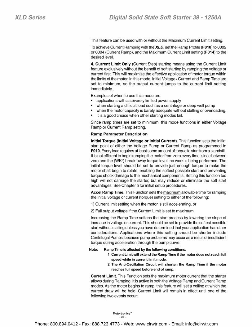
Motortronics™
- 48 -
XLD Series Digital Solid State Soft Starter 39 - 1250A
This feature can be used with or without the Maximum Current Limit setting.
To achieve Current Ramping with the XLD, set the Ramp Profile (F010) to 0002or 0004 (Current Ramp), and the Maximum Current Limit setting (F014) to thedesired level.
4. Current Limit Only (Current Step) starting means using the Current Limitfeature exclusively without the benefit of soft starting by ramping the voltage orcurrent first. This will maximize the effective application of motor torque withinthe limits of the motor. In this mode, Initial Voltage / Current and Ramp Time areset to minimum, so the output current jumps to the current limit settingimmediately.
Examples of when to use this mode are:• applications with a severely limited power supply• when starting a difficult load such as a centrifuge or deep well pump• when the motor capacity is barely adequate without stalling or overloading.• It is a good choice when other starting modes fail.
Since ramp times are set to minimum, this mode functions in either VoltageRamp or Current Ramp setting.
Ramp Parameter DescriptionInitial Torque (Initial Voltage or Initial Current). This function sets the initialstart point of either the Voltage Ramp or Current Ramp as programmed inF010. Every load requires at least some amount of torque to start from a standstill.It is not efficient to begin ramping the motor from zero every time, since betweenzero and the (WK2) break-away torque level, no work is being performed. Theinitial torque level should be set to provide just enough torque to make themotor shaft begin to rotate, enabling the softest possible start and preventingtorque shock damage to the mechanical components. Setting this function toohigh will not damage the starter, but may reduce or eliminate the soft startadvantages. See Chapter 5 for initial setup procedures.
Accel Ramp Time. This Function sets the maximum allowable time for rampingthe Initial voltage or current (torque) setting to either of the following:
1) Current limit setting when the motor is still accelerating, or
2) Full output voltage if the Current Limit is set to maximum.
Increasing the Ramp Time softens the start process by lowering the slope ofincrease in voltage or current. This should be set to provide the softest possiblestart without stalling unless you have determined that your application has otherconsiderations. Applications where this setting should be shorter includeCentrifugal Pumps, because pump problems may occur as a result of insufficienttorque during acceleration through the pump curve.
Note: Ramp Time is affected by the following conditions:1. Current Limit will extend the Ramp Time if the motor does not reach full
speed while in current limit mode.2. The Anti-Oscillation Circuit will shorten the Ramp Time if the motor
reaches full speed before end of ramp.
Current Limit. This Function sets the maximum motor current that the starterallows during Ramping. It is active in both the Voltage Ramp and Current Rampmodes. As the motor begins to ramp, this feature will set a ceiling at which thecurrent draw will be held. Current Limit will remain in effect until one of thefollowing two events occur:
Phone: 800.894.0412 - Fax: 888.723.4773 - Web: www.clrwtr.com - Email: [email protected]
Motortronics™
- 49 -
XLD Series Digital Solid State Soft Starter 39 - 1250A
1) The motor reaches full speed as detected by the At-Speed detection circuit.
2) The Overload Protection trips on Motor Thermal Overload (see Ch.3).
Once the motor has reached full speed, the Current Limit feature becomesinactive.
In the Voltage Ramp Profile, the Voltage output is increased until the CurrentLimit is reached. The Ramp Time is the maximum time it will take for the voltageto increase until the Current Limit setting takes over. Under some load conditions,Current Limit may be reached before the Ramp Time has expired.
In the Current Ramp Profile, output voltage varies to provide a linear increase incurrent up to the Current Limit setting, and Ramp Time is the time that it will taketo get there. A closed loop feedback of motor current allows continuous updatingof the output to maintain this ramp profile.
Because most AC induction motors will not start below 200% current, the currentlimit set point is adjustable down to only 200%.. Use this feature to preventvoltage drop in your electrical supply, portable / emergency generator stalling,or to satisfy utility restrictions on starting power.
Caution: While the XLD is in Start mode there is no maximum Current Limittime. Excessive start time may however lead to motor stalling, causing anOverload Trip. If this happens, try raising the Current Limit setting to accommodateyour load conditions. If the Current Limit setting cannot be increased, try usingCurrent Limit without ramping features (“Current Limit Only” as describedpreviously).
Phone: 800.894.0412 - Fax: 888.723.4773 - Web: www.clrwtr.com - Email: [email protected]

Motortronics™
- 50 -
XLD Series Digital Solid State Soft Starter 39 - 1250A
Appendix 2: Decel Mode Application ConsiderationsDeceleration (Soft Stop) is a unique feature of Solid State Soft Starters suchas the XLD. It provides a slow decrease in the output voltage, accomplishinga gentle decrease in motor torque during the stopping mode. This is theOPPOSITE OF BRAKING in that it will take longer to come to a stop than ifthe starter were just tuned off. The primary use of this function is withcentrifugal pumps as a means to reduce the sudden changes in pressurethat are associated with “Water Hammer” and slamming of check valves.Decel control in pump applications is often referred to as Pump Control.In a pump system, liquid is being pushed uphill. The force exerted by gravityon the column of liquid as it goes up hill is called the “Head Pressure” in thesystem. The pump is sized to provide enough Output Pressure to overcomethe Head Pressure and move the fluid up the pipe. When the pump is turnedoff, the Output Pressure rapidly drops to zero and the Head Pressure takesover to send the fluid back down the hill. A “Check Valve” is used somewherein the system to prevent this (if necessary) by only allowing the liquid to flowin one direction. The kinetic energy in that moving fluid is suddenly trappedwhen the valve slams closed. Since fluids can’t compress, that energy istransformed into a “Shock Wave” that travels through the piping systemlooking for an outlet in which to dissipate. The sound of that shock wave isreferred to as “Water Hammer”. The energy in that shock wave can beextremely damaging to pipes, fittings, flanges, seals and mounting systems.
By using the Soft Stop deceleration feature of the XLD, the pump outputtorque is gradually and gently reduced, which slowly reduces the pressure inthe pipe. When the Output Pressure is just slightly lower than the HeadPressure, the flow slowly reverses and closes the Check Valve. By this timethere is very little energy left in the moving fluid and the Shock Wave isavoided. When the output voltage to the motor is low enough to no longer beneeded, the XLD will end the Decel cycle and turn itself off.
Another common application is on material handling conveyors as a meansto prevent sudden stops that may cause products to fall over or to bump intoone another. In overhead crane applications, Soft Stopping of the Bridge orTrolley can prevent loads from beginning to over swing on sudden stops.
Volts
100%
60%
30%
BDLBegin Decel LevelF026
Stop Commandfrom controlsystem
Decel Ramp TimeF028
Decel Shut-OffLevelF027
Output to Motor
PUMP FLOW
BACK FLOW
SHOCK WAVE
NO SHOCK WAVE
NEUTRAL PRESSURE
PUMPON
PUMPOFF
PUMPOFF
PUMPOFF
PUMPSOFTSTOP
Check ValveOpen
Check ValveSlams
Check ValveClosed
Check ValveCloses Slowly
Check ValveClosed
Pump Control Soft Stop with RVSS
Coasting Stop (using Electro-Mech. starter)
Phone: 800.894.0412 - Fax: 888.723.4773 - Web: www.clrwtr.com - Email: [email protected]

Motortronics™
- 51 -
XLD Series Digital Solid State Soft Starter 39 - 1250A
Appendix 3: Parameter Lock / User Password InstructionsProvides users with the ability to prevent unauthorized operators from makingchanges to the programmed functions. If you do not need to take advantageof this feature, do not enter anything into this function. The factory defaultis disabled, and no Password is necessary to make changes to the program.
When any value other than 0 is entered into this Function, the Parameter Lockis enabled and that number becomes the User Password. From that pointforward, it will be necessary to enter the User Password in this Function priorto making changes in any programmed function, including this one. When theParameter Lock has been enabled, attempts to alter the program will result inthe display reading Err whenever the READ / ENTER key is pressed.
To be able to alter the program after the Parameter Lock has been enabled,go to Function (F060) and enter the correct user Password. When the READ/ ENTER button is pressed, the display will read PASS, indicating that theUser Password is correct and the system is unlocked. You will have 5 minutesin which to make a change in the program. This 5 minute window resetswhenever any key is pressed, so it floats to give you 5 minutes after the lastentry. After 5 minutes of no keypad activity, the Parameter Lock is reinstatedwith the current user Password. Subsequent changes will require re-enteringthe User Password.To change the User Password or to disable the Parameter Lock function,enter the programmed User Password first, then set Function F060 to 0 (F060= 0), disabling the Parameter Lock. If you do not re-enter the Password orenter a new user password, the Parameter Lock feature will remain disabled.If you enter a different number into this Function, the new number becomesyour new User Password.
The User Password will not be displayed after being entered or at any othertime. The number displayed after the READ / ENTER key is initially pressedis for reference only. Caution: DO NOT LOSE YOUR PASSWORD. If the passwordhas been lost or forgotten, contact Motortronics for assistance in retrievingit with authorization.
Enabling Password Protection / Parameter Lock (See Example)Start from the Status Display Mode.Press the Fn key.Press the LEFT arrow to select the second digit (from the right)Press the UP arrow six times (6x) to change the function code to F061.Press the RIGHT arrow to select the first digit (from the right).Press the DOWN arrow to change the function code to F060.Press the Read Enter key. The display should “hide” the password.Use the UP arrow and the LEFT arrow to display thepassword you desire (Valid range is 0000 to 0999).In this example, 0123 has been selected.Press the Read Enter key. The word [END] should momentarily display to confirmyou have enabled the user password feature.Disabling Password Protection / Parameter LockoutChanging function F060 to 0000 will disable the user password.
F060 = Parameter Lock / User PasswordFactory Setting = 0 (disabled)Range = 0 - 999
ExamplePassword = 0123
Enabling PasswordProtection
Phone: 800.894.0412 - Fax: 888.723.4773 - Web: www.clrwtr.com - Email: [email protected]

Motortronics™
- 52 -
XLD Series Digital Solid State Soft Starter 39 - 1250A
Appendix 4 - Soft Starter SettingsThe following chart may be used to record the changes made to the factory settings.
Fn Function Page Set To Check Revised Check
F001 Motor FLA 20
F002 Service Factor 21
F003 Overload Class During Start 21
F004 Overload Class During Run 21
F005 Overload Reset 21
F006-F009 Reserved
F010 Ramp Select 21
F011 Initial Voltage of Ramp 1 22
F012 Initial Current of Ramp 1 22
F013 Accel Ramp Time of Ramp 1 22
F014 Max Current Limit of Ramp 1 22
F015 Initial Voltage of Ramp 2 23
F016 Initial Current of Ramp 2 23
F017 Accel Ramp Time of Ramp 2 23
F018 Max Current Limit of Ramp 2 23
F019 Voltage Jog 24
F020 Time of Voltage Jog 24
F021 Current Jog 24
F022 Kick Start 24
F023 Kick Voltage 24
F024 Kick Time 25
F025 Deceleration Ramp 25
F026 Begin Decel Level (BDL) 25
F027 Decel Shut Off Voltage 25
F028 Decel Ramp Time 25
F029 Reserved
F030 Current Imbalance Trip 26
F031 Current Imbalance Trip % 26
F032 Current Imbalance Trip Delay 26
F033 Over Current Trip 26
F034 Over Current Trip % 26
F035 Over Current Trip Delay 26
F036 Under Current Trip 26
F037 Under Current Trip % 26
F038 Under Current Trip Delay 26
F039 Coast Down Lockout Timer 27
No record required
No record required
Phone: 800.894.0412 - Fax: 888.723.4773 - Web: www.clrwtr.com - Email: [email protected]

Motortronics™
- 53 -
XLD Series Digital Solid State Soft Starter 39 - 1250AFn Function Page Set To Check Revised Check
F040 Coast Down Lockout Time 27
F041 Starts per Hour Lockout 27
F042 Maximum Starts per Hour 27
F043 Time Between Starts Lockout 27
F044 Minimum Time Between Starts 27
F045-F049 Coast Down, Starts/Hr, Thermal Capacity
F050 Aux Relay 1 Setting 28
F051 Aux Relay 2 Setting 28
F052 Aux Relay 3 Setting 28
F053-F054 Reserved
F055 Communications 29
F056 Baud Rate 29
F057 Modbus Address 29
F058 Remote Starter Control 30
F059 Reserved
F060 Parameter Lock/Customer Password 30
F061 Reset Factory Default Settings 30
F062 Reserved
F063 Factory Use
F064 Factory Use
F065 Year 31
F066 Month 31
F067 Day 31
F068 Hour 31
F069 Minute 31
F070 Second 31
F071 Factory Use
F072-F074 Reserved
F075 Fault History #1, Latest Fault 31
F076 Time Stamp, Fault #1 31
F077 Date Stamp, Fault #1 31
F078 Fault History #2, Previous Fault 31
F079 Time Stamp, Fault #2 32
F080 Date Stamp, Fault #2 32
F081 Fault History #3, Oldest Fault 32
F082 Time Stamp, Fault #3 32
F083 Date Stamp, Fault #3 32
F084-F087 Reserved
No record required
No record required
No record required
No record required
No record required
No record required
No record required
No record required
Display Only
Phone: 800.894.0412 - Fax: 888.723.4773 - Web: www.clrwtr.com - Email: [email protected]

Motortronics™
- 54 -
XLD Series Digital Solid State Soft Starter 39 - 1250A
Phone: 800.894.0412 - Fax: 888.723.4773 - Web: www.clrwtr.com - Email: [email protected]

- 55 -
XLD Series Digital Solid State Soft Starter 39 - 1250A
MOTORTRONICS™ warrants its products to be free from defects in mate-rial and/or workmanship for a period of one year from the date of installa-tion, to a maximum of 18 months from the date of shipment as indicated bythe unit’s date code. Extended warranties are available, please contact fac-tory for details. The Company reserves the right to repair or replace anymalfunctioning units under warranty at their option. All warranty repairs mustbe performed by the Company factory, or on site by factory authorized ser-vice firms or personnel approved by the Company.
Solid state controls have different operating characteristics from those ofelectromechanical equipment. Because of these differences and the widevariety of applications for solid state controls, each application designermust verify that the solid state equipment is acceptable for his application.In no event will MOTORTRONICS™ be liable or responsible for indirect orconsequential damages resulting from the use or application of this equip-ment. The diagrams and illustrations in this document are included solelyfor illustrative purposes. Because of the number of different applications,MOTORTRONICS™ can not be responsible or liable for actual use basedon the examples or diagrams.
Warranty Policy
Phone: 800.894.0412 - Fax: 888.723.4773 - Web: www.clrwtr.com - Email: [email protected]