Motorola GGM 8000 Gateway - NIST · This document defines the Security Policy for the Motorola GGM...
28
Page 1 of 28 Motorola GGM 8000 Gateway FIPS 140-2 Cryptographic Module Non-Proprietary Security Policy Version: 2.3.1 Date: 5/31/2018
Transcript of Motorola GGM 8000 Gateway - NIST · This document defines the Security Policy for the Motorola GGM...

Page 1 of 28
Motorola GGM 8000 Gateway
FIPS 140-2 Cryptographic Module Non-Proprietary Security Policy
Version: 2.3.1
Date: 5/31/2018

Page 2 of 28
Table of Contents
1 Introduction .................................................................................................................... 4
1.1 Hardware and Physical Cryptographic Boundary ........................................................................ 6 1.2 Modes of Operation ..................................................................................................................... 7
2 Cryptographic Functionality ............................................................................................ 8
2.1 Critical Security Parameters ....................................................................................................... 11 2.2 Public Keys ................................................................................................................................. 14
3 Roles, Authentication and Services ................................................................................ 15
3.1 Assumption of Roles .................................................................................................................. 15 3.2 Authentication Methods ............................................................................................................ 16 3.3 Services ...................................................................................................................................... 16
4 Self-tests ....................................................................................................................... 20
5 Physical Security Policy.................................................................................................. 21
6 Operational Environment .............................................................................................. 21
7 Mitigation of Other Attacks Policy ................................................................................. 21
8 Security Rules and Guidance ......................................................................................... 22
9 References and Definitions ............................................................................................ 24
10 GGM 8000 GATEWAY TAMPER EVIDENCE LABEL INSTALLATION INSTRUCTIONS ........... 25

Page 3 of 28
List of Tables
Table 1 – Cryptographic Module Configurations ...................................................................................................... 4 Table 2 – Security Level of Security Requirements ................................................................................................... 4 Table 3 – Ports and Interfaces ................................................................................................................................... 6 Table 4 – FIPS Approved Mode Configuration .......................................................................................................... 7 Table 5 – Approved and CAVP Validated Cryptographic Functions .......................................................................... 8 Table 6 – Approved Cryptographic Functions Tested with Vendor Affirmation ..................................................... 10 Table 7 – Non-Approved but Allowed Cryptographic Functions ............................................................................. 10 Table 8 – Protocols Allowed in FIPS Mode .............................................................................................................. 11 Table 9 – Critical Security Parameters (CSPs) .......................................................................................................... 12 Table 10 – Public Keys ............................................................................................................................................. 14 Table 11 – Roles Description ................................................................................................................................... 15 Table 12 – Authenticated Services .......................................................................................................................... 16 Table 13 – Unauthenticated Services ...................................................................................................................... 17 Table 14 – CSP Access Rights within Services .......................................................................................................... 18 Table 15 – Power Up Self-tests ................................................................................................................................ 20 Table 16 – Conditional Self-tests ............................................................................................................................. 21 Table 17 – References ............................................................................................................................................. 24 Table 18 – Acronyms and Definitions ...................................................................................................................... 24
List of Figures
Figure 1 – Motorola GGM 8000 Gateway with Ports ................................................................................................ 6 Figure 2 – Applying Tamper Evidence Labels 1, 2, and 3 to Secure the GGM 8000 Base Unit (Base Module and Blank Filler Panel in Expansion Module Slot ............................................................................................................ 26

Page 4 of 28
1 Introduction This document defines the Security Policy for the Motorola GGM 8000 Gateway, hereafter denoted the Module. The Module is a modular purpose-built gateway that can easily be configured to support a variety of public safety network applications. The Module meets FIPS 140-2 overall Level 2 requirements.
Table 1 – Cryptographic Module Configurations
Module HW P/N and Version FW Version
1 GGM 8000 Base Unit
CLN1841F Rev AB KS 16.9.0.48
2 GGM 8000 AC Power Supply option
CLN1850A Rev G N/A
3 GGM 8000 DC Power Supply option
CLN1849C Rev AA N/A
4 FIPS Kit CLN8787A, Rev. B N/A
The Module is intended for use by US Federal agencies and other markets that require FIPS 140-2 validated network appliances. The Module is a multi-chip standalone embodiment; the cryptographic boundary is the gateway’s enclosure which includes all components, and one of the power supply options (AC or DC) identified in Table 1.
The FIPS 140-2 security levels for the Module are as follows:
Table 2 – Security Level of Security Requirements
Security Requirement Security Level
Cryptographic Module Specification 2
Cryptographic Module Ports and Interfaces 2
Roles, Services, and Authentication 2
Finite State Model 2
Physical Security 2
Operational Environment N/A
Cryptographic Key Management 2
EMI/EMC 2
Self-Tests 2
Design Assurance 3
Mitigation of Other Attacks N/A

Page 5 of 28
The Module implementation is compliant with: • FIPS 140-2 • FIPS 197 • SP 800-38A • SP 800-90A • FIPS 198-1 • SP 800-135 • FIPS 186-4 • FIPS 180-4 • SP 800-20 • SP 800-56A

Page 6 of 28
1.1 Hardware and Physical Cryptographic Boundary
The physical cryptographic boundary of the Module is depicted in Figure 1. In the photo, there is a slot that can hold an optional expansion module for increased device connectivity. The optional expansion module is not included within the Motorola GGM 8000 Gateway cryptographic boundary.
Figure 1 – Motorola GGM 8000 Gateway with Ports
Table 3 – Ports and Interfaces
Port Description Logical Interface Type
Ethernet (Qty. 4) LAN ports that provide connection to Ethernet LANs using either 10BASE-T, 100BASE-TX, or 1 Gigabit Ethernet
Control in | Data in | Data out | Status out
T1/E1 (Qty. 2) T1/E1 interfaces that support T1/E1 CSU/DSU
Control in | Data in | Data out | Status out
Console (Qty. 1) RS-232 interface Control in | Status out
Backplane interface Supports expansion module containing optional interface cards (expansion module not part of cryptographic boundary)
High-speed multifunction serial interfaces that provide connection to industry-standard V.35, Data Communications Equipment (DCE) or Data Terminal Equipment (DTE) serial devices
Control in | Data in | Data out | Status out
AC power plug Power
Ethernet Ports
T1/E1 Ports
Console Port
LEDs
AC Power Plug or DC Power Entry Connectors on rear of chassis
Backplane Interface (supports Expansion Module – not part of cryptographic
boundary)

Page 7 of 28
Port Description Logical Interface Type
-OR- DC power entry connectors (Qty. 1 or 2)
External AC power input port -OR- External DC power input ports
Power
LEDs (Qty. 7) Provide Module status for traffic and module power.
Status out
1.2 Modes of Operation
The module supports both an Approved and non-Approved mode of operation. To enter FIPS mode, the Crypto-Officer must follow the procedure outlined in Table 4 below. For details on individual gateway commands, use the online help facility or review the Enterprise OS Software User Guide and the Enterprise OS Software Reference Guide.
Table 4 – FIPS Approved Mode Configuration
Step Description
1. Check if FIPS mode is enabled using the show -SYS FIPS command. If FIPS = ON, go to next step. If FIPS = OFF, issue SETD -SYS FIPS=ON command.
2. Configure the parameters for the IKE negotiations using the IKEProfile command. For FIPS mode, only the following values are allowed: Diffie-Hellman Group (Group 14 required for 112-bit key strength, Group 19 for 128-bit key strength or Group 20 for 192-bit key strength), Encryption Algorithm (AES or Triple-DES), Hash Algorithm (SHA, SHA-256 or SHA-384), and Authentication Method (PreSharedKey, RSA-Signature, ECDSA-256 or ECDSA-384).
3. If PreSharedKey is used as Authentication Method, electronically establish via the local console port the pre-shared key (PSK) to be used for the IKE protocol using:
ADD -CRYPTO FipsPreSharedKey <peer_ID> <pre-shared_key> <pre-shared_key>
For FIPS mode, minimum key length is 14 bytes.
4. If RSA-Signature, ECDSA-256 or ECDSA-384 is used as Authentication Method:
a. Unlock PKI database using: SETD -PKI CONTrol = Unlocked
b. Generate key pair using: ADD -PKI KeyPair [<profile>] [<RSA|ECDSA>] <256|384|2048>
c. Set identity of the device by executing at least one of the following commands: SETD -PKI DNSName = <dns-name> SETD -PKI IPADDress = <ip-address> SETD -PKI EmailADDress = <email-address> SETD -PKI SubjectName = <subject-name>
d. Generate CSR using: ADD -PKI CertReq <certreq-profile>
e. Use external CA to generate certificate from CSR f. Install chain of certificates using:
ADD -PKI CERTificate <profile> <Self|TrustedCA|UnTrusted> InputFile <local-file-name> g. Lock PKI database using:
SETD -PKI CONTrol = Locked

Page 8 of 28
Step Description
5. If IPsec is used, configure IPsec transform lists using the ADD -CRYPTO TransformLIst command. For FIPS mode, only the following values are allowed: Encryption Transform (ESP-3DES, or ESP-AES) and Authentication Transform (ESP-SHA).
6. If FRF.17 is used, configure FRF.17 transform lists using the ADD -CRYPTO TransformLIst command. For FIPS mode, only the following values are allowed: Encryption Transform (FRF-3DES, or FRF-AES) and Authentication Transform (FRF-SHA).
7. For each port for which encryption is required, bind a dynamic policy to the ports using:
ADD [!<portlist>] -CRYPTO DynamicPOLicy <policy_name> <priority>
<mode> <selctrlist_name> <xfrmlist_name> [<pfs>] [<lifetime>] [<preconnect>]
To be in FIPS mode, the selector list and transform list names must be defined as in previous steps.
8. If PIM authentication is enabled, configure Manual Key set using the ADD -CRYPTO ManKeySet command. For FIPS mode, minimum authentication key length is 14 bytes.
9. If SNMPv3 is enabled, configure authentication and encryption passphrases for all SNMP users with AuthPriv privileges. For FIPS mode, minimum authentication passphrase length is 14 bytes.
10. Enable SSHv2 using the SETDefault -SYS NetAccess = Ssh command. Generate RSA 2048 bit keys using the GenSshKey RSA 2048 command.
11. For each port for which encryption is required, enable encryption on that port using:
SETDefault [!<portlist>] -CRYPTO CONTrol = Enabled
12. DSA keys must not be used in FIPS mode.
13. Use the Show -SYS SwSignatureAlgorithm command to verify that firmware signing algorithm is set to SHA2withRSA2048. If not use the SetD -SYS SwSignAlgorithm = SHA2withRSA2048 command to change signing algorithm.
14. Copy command must not be used to transfer files outside the module in FIPS mode. SCP protocol can be use instead of.
15. FIPS-140-2 mode achieved.
2 Cryptographic Functionality The Module implements the FIPS Approved and Non-Approved but Allowed cryptographic functions listed in the table(s) below.
Table 5 – Approved and CAVP Validated Cryptographic Functions
Algorithm Description Cert #
AES (Hardware Implementation)
[FIPS 197, SP 800-38A] Functions: Encryption, Decryption Modes: ECB, CBC, CTR Key sizes: 128, 256 bits
962

Page 9 of 28
Algorithm Description Cert #
AES (Firmware Implementation)
[FIPS 197, SP 800-38A] Functions: Encryption, Decryption Modes: ECB, CBC, CFB128, CTR Key sizes: 128 (ECB, CBC, CFB128, CTR), 192 (ECB, CBC, CTR), 256 (ECB, CBC, CTR) bits
3993
DRBG
[SP 800-90A] Functions: Hash DRBG Security Strengths: 128 bits
1184
ECDSA [FIPS 186-4] Functions: Key Pair Generation, Signature Generation, Signature Verification Curves: P-256, P-384
887
HMAC (Hardware Implementation)
[FIPS 198-1] Functions: Generation, Verification SHA sizes: SHA-1 Key Size: 160 bits
1487
HMAC (Firmware Implementation)
[FIPS 198-1] Functions: Generation, Verification SHA sizes: SHA-1, SHA-256, SHA-384 Key Size: minimum 112 bits
2606, 2607
KAS Component (All except KDF)
[SP 800-56A] Functions: Key Pair Generation, Full Validation Modes: ECC Roles: Initiator, Responder Parameter sets: P-256 with SHA-256, P-384 with SHA-384
CVL #816
KDF, Existing Application-Specific (CVL)
[SP 800-135] Functions: SSH KDF, SNMP KDF, IKE v1 KDF, IKEv2 KDF
817, 818, 819
KTS [SP800-38F §3.1] Functions: Key Unwrap Modes: AES-CTR + HMAC-SHA-1, AES-CBC + HMAC-SHA-1
AES #3993 HMAC #2606, #2607
RSA
[FIPS 186-4, PKCS #1 v2.1 (PKCS1.5)] Functions: Key Generation, Signature Generation, Signature Verification Key sizes: 1024 (RSA Verify only), 2048 bits
2049

Page 10 of 28
Algorithm Description Cert #
SHA (Hardware Implementation)
[FIPS 180-4] Functions: Message Digest SHA sizes: SHA-1
933
SHA (Firmware Implementation)
[FIPS 180-4] Functions: Digital Signature Generation, Digital Signature Verification, non-Digital Signature Applications SHA sizes: SHA-1, SHA-256, SHA-384
3295
Triple-DES (TDEA) (Hardware Implementation)
[SP 800-20] Functions: Encryption, Decryption Modes: TCBC Key sizes: 3-key
757
Triple-DES (TDEA) (Firmware Implementation)
[SP 800-20] Functions: Encryption, Decryption Modes: TCBC Key sizes: 3-key
2192
Table 6 – Approved Cryptographic Functions Tested with Vendor Affirmation
Algorithm Description
KAS [SP 800-56A] Modes: KAS Component (CVL #816) + KDF (CVL #817 [SSH] or CVL #819 [IKE])
Table 7 – Non-Approved but Allowed Cryptographic Functions
Algorithm Description
Non-SP 800-56A Compliant DH
[IG D.8] Diffie-Hellman (key agreement; key establishment methodology provides 112 bits of encryption strength)
NDRNG [Annex C] Hardware Non-Deterministic RNG; minimum of 256 bits per access. The NDRNG output is used to seed the FIPS Approved DRBG.

Page 11 of 28
Table 8 – Protocols Allowed in FIPS Mode
Protocol Description
IKE v1
[IG D.8 and SP 800-135] Cipher Suites:
• Oakley Group 14 DH key agreement or Oakley Group 19 and 20 ECDH key agreement
• PreSharedKey, RSA-Signature, ECDSA-256 or ECDSA-384 authentication • AES or Triple-DES CBC encryption • SHA-1, SHA-256 or SHA-384 hashing • HMAC as PRF
IKE v2
[IG D.8 and SP 800-135] Cipher Suites:
• Oakley Group 14 DH key agreement • PreSharedKey authentication • AES or Triple-DES CBC encryption • HMAC-SHA-1, HMAC-SHA-256 or HMAC-SHA-384 integrity and PRF
SNMPv3 [IG D.8 and SP 800-135] Allowed only with the SP 800-135 SNMP KDF and AES encryption/decryption
SSH v2
[IG D.8 and SP 800-135] Cipher Suites: RSA 2048 DH group 14 SHA-1 key transport, AES CBC or CTR encryption, HMAC-SHA-1 MAC
Note: these protocols have not been reviewed or tested by CMVP or CAVP
Non-Approved Cryptographic Functions for use in non-Approved mode only:
• DES • Triple-DES (2-Key) • FIPS 186-2 RSA Signature Generation: 4096 bit keys with SHA-2 • MD5 • HMAC-MD5 • HMAC-SHA-1-96 • DSA 1024-bit – for public/private key pair generation and digital signatures (non-compliant) • RSA 1024 – for key transport within SSH v2 • Non approved SW RNG: Provides random numbers for networking functions (non-compliant) • Diffie-Hellman Group 1, 2 and 5 • Non-SP 800-38F Compliant Key Wrap: AES-ECB Key Wrap and Key Unwrap (key wrapping; key
establishment methodology provides 128 bits of encryption strength)
2.1 Critical Security Parameters
All CSPs used by the Module are described in this section. All usage of these CSPs by the Module (including all CSP lifecycle states) is described in the services detailed in Section 3.

Page 12 of 28
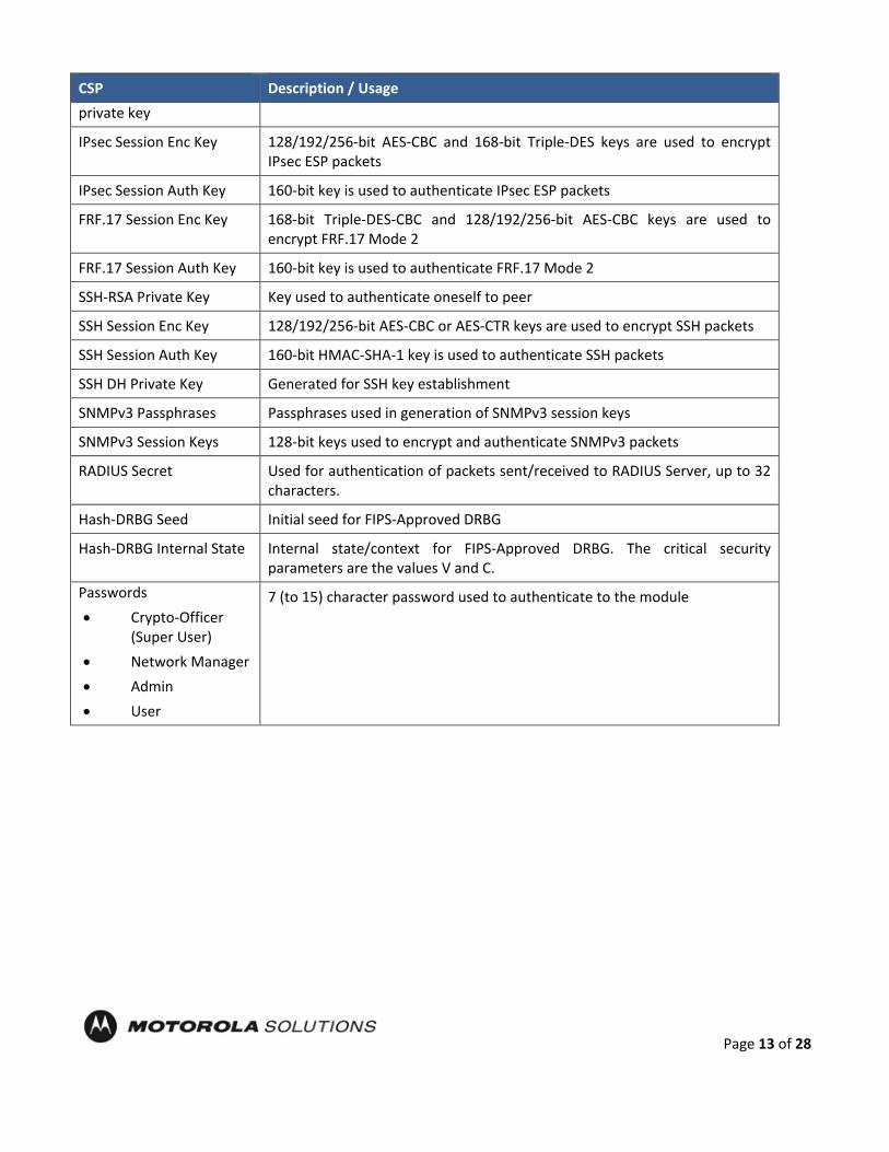
Table 9 – Critical Security Parameters (CSPs)
CSP Description / Usage
KEK This is the master key that encrypts persistent CSPs stored within the module.
KEK-protected keys include PSK and passwords.
Encryption of keys uses AES128ECB
IKE Preshared Keys Used to authenticate peer to peer during IKE session
PKI private key 2048-bit RSA or 256/384-bit ECDSA key used for certificate request signing and IKEv1 authentication
SKEYID HMAC-SHA-1, HMAC-SHA-256 or HMAC-SHA-384 (minimum 112 bit key), used in IKE to provide for authentication of peer router.
Generated for IKE Phase 1 by hashing preshared keys with responder/receiver nonce
SKEYID_d Phase 1 key used to derive keying material for IKE SAs
SKEYID_a Key used for integrity and authentication of the phase 1 exchange
SKEYID_e Key used for Triple-DES or AES data encryption of phase 1 exchange
SKEYSEED Seed value is generated from initiator and responder nonce values and DH –pre-shared key. Used in IKEv2 IKE_SA
SK_d Key used to derive keying material for the CHILD_SAs established with IKEv2 IKE_SAs
SK_ai Key used by initiator as a key to the integrity protection algorithm for authenticating the component messages in IKEv2 IKE_SA
SK_ar Key used by responder as a key to the integrity protection algorithm for authenticating the component messages in IKEv2 IKE_SA
SK_ei Key used by initiator for encrypting and decrypting all subsequent exchanges in IKEv2 IKE_SA
SK_er Key used by responder for encrypting and decrypting all subsequent exchanges in IKEv2 IKE_SA
SK_pi Key used by initiator when generating an AUTH payload in IKEv2 IKE_SA
SK_pr Key used by responder when generating an AUTH payload in IKEv2 IKE_SA
Ephemeral DH Phase-1 private key (a)
Generated for IKE Phase 1 key establishment
Ephemeral ECDH Phase-1 private key
Generated for IKEv1 Phase 1 key establishment
Ephemeral DH Phase-2 private key (a)
Phase 2 Diffie-Hellman private keys used in PFS for key renewal
Ephemeral ECDH Phase-2 Phase 2 Elliptic Curve Diffie-Hellman private keys used in PFS for key renewal
Page 13 of 28
CSP Description / Usage private key
IPsec Session Enc Key 128/192/256-bit AES-CBC and 168-bit Triple-DES keys are used to encrypt IPsec ESP packets
IPsec Session Auth Key 160-bit key is used to authenticate IPsec ESP packets
FRF.17 Session Enc Key 168-bit Triple-DES-CBC and 128/192/256-bit AES-CBC keys are used to encrypt FRF.17 Mode 2
FRF.17 Session Auth Key 160-bit key is used to authenticate FRF.17 Mode 2
SSH-RSA Private Key Key used to authenticate oneself to peer
SSH Session Enc Key 128/192/256-bit AES-CBC or AES-CTR keys are used to encrypt SSH packets
SSH Session Auth Key 160-bit HMAC-SHA-1 key is used to authenticate SSH packets
SSH DH Private Key Generated for SSH key establishment
SNMPv3 Passphrases Passphrases used in generation of SNMPv3 session keys
SNMPv3 Session Keys 128-bit keys used to encrypt and authenticate SNMPv3 packets
RADIUS Secret Used for authentication of packets sent/received to RADIUS Server, up to 32 characters.
Hash-DRBG Seed Initial seed for FIPS-Approved DRBG
Hash-DRBG Internal State Internal state/context for FIPS-Approved DRBG. The critical security parameters are the values V and C.
Passwords • Crypto-Officer
(Super User) • Network Manager • Admin • User
7 (to 15) character password used to authenticate to the module

Page 14 of 28
2.2 Public Keys
Table 10 – Public Keys
Key Description / Usage RSA Firmware Load Key RSA 2048 bit key used for firmware authentication SSH-RSA Key (RSA 2048-bit) Distributed to peer, used for SSH authentication SSH Known Host Keys (RSA 1024 and 2048-bit) Distributed to module, used to authenticate peer IKE DH public key (g^a) (2048-bit) Generated for IKE Phase 1 key establishment IKE ECDH public key (256/384-bit) Generated for IKEv1 Phase 1 key establishment IKE DH phase-2 public (g^a) key
(2048–bit) Phase 2 Diffie-Hellman public keys used in PFS for key renewal (if configured)
IKE ECDH phase-2 public key
(256/384-bit) Phase 2 Elliptic Curve Diffie-Hellman public keys used in PFS for key renewal (if configured)
SSH DH Key (2048-bit) Generated for SSH key establishment PKI public key (RSA 2048-bit or ECDSA 256/384-bit) Generated for IKEv1 authentication

Page 15 of 28
3 Roles, Authentication and Services 3.1 Assumption of Roles
The module supports seven distinct operator roles, Cryptographic Officer (Super User), Admin, Network Manager, User, MotoAdmin, MotoMaster, and MotoInformA/B. The cryptographic module enforces the separation of roles using Role-based authentication. The Crypto Officer and Network Manager roles can drop down to the User privilege level without a password.
Table 9 lists all operator roles supported by the module. The Module supports concurrent operators. Each operator has an independent session with the gateway, either though SSH (via Ethernet port), via the console, or over SNMPv3 (via Ethernet port) when specified. Once authenticated to a role, each operator can access only those services for that role. In this way, separation is maintained between the role and services allowed for each operator.
Table 11 – Roles Description
Role ID Role Description Authentication Type Authentication Data
Crypto-Officer (Super User)
The owner of the cryptographic module with full access to services of the module.
Role-based operator authentication.
Username and Password
Network Manager (NM)
An operator of the module with almost full access to services of the module.
Role-based operator authentication.
Username and Password
Admin An assistant to the Crypto-Officer that has read only access to a subset of module configuration and status indications.
Role-based operator authentication.
Username and Password
User A user of the module that has read only access to a subset of module configuration and status indications.
Role-based operator authentication.
Username and Password
MotoAdmin (MO)
A SNMPv3 user who can issue any command from the SNMP V3 User Manager menu.
Role-based operator authentication.
Passphrase
MotoMaster (MM)
A SNMPv3 user who can change its own passphrases from the SNMP V3 User Manager menu.
Role-based operator authentication.
Passphrase

Page 16 of 28
Role ID Role Description Authentication Type Authentication Data
MotoInformA/B (MI)
A SNMPv3 user who receives and transmits reliable messages over SNMPv3.
Role-based operator authentication.
Passphrase
3.2 Authentication Methods
Username and Password
Passwords are alphanumeric strings consisting of 7 to 15 characters chosen from the 94 standard keyboard characters. The probability that a random attempt will succeed or a false acceptance will occur is 1/94^7 which is less than 1/1,000,000. After three consecutive unsuccessful login attempts, an operator is locked out for two minutes, ensuring that that the probability is less than one in 100,000 per minute, that random multiple attempts will succeed or a false acceptance will occur.
Passphrase
Each SNMPv3 user has its own pair of encryption and authentication passphrases. The SNMPv3 user authentication or encryption passphrase must be 8-64 characters long and may contain uppercase and lowercase alphabetic characters (A-Z) and (a-z); numeric characters (0-9); and any of the following special characters (! “ % & ” ( ) * + , - . /: ; < = > ?).
The probability that a random attempt will succeed or a false acceptance will occur is 1/81^8 which is less than 1/1,000,000. The timing of the SNMPv3 authentication protocol as implemented limits the probability of randomly guessing a SNMPv3 passphrase in 60 seconds to less than 1 in 100,000. Assuming 1 ms for processing each authentication attempt, the probability that a false acceptance will occur in a one minute period is 60000/81^8 = 3.24/10^11 and it is less than 1/10^5. One authentication attempt takes about 100 ms in real-life scenario. 3.3 Services
All services implemented by the Module are listed in the tables below. Each service description also describes all usage of CSPs by the service.
Table 12 – Authenticated Services
Service Description CO NM Admin User MO MM MI
Firmware Update Load firmware images digitally signed by RSA (2048 bit) algorithm
X X
Key Entry Enter Pre-Shared Keys (PSK) X X
User Management
Add/Delete and manage operator passwords
X X
Reboot Force the module to power cycle via a command
X X

Page 17 of 28
Service Description CO NM Admin User MO MM MI
Zeroization Actively destroy all plaintext CSPs and keys
X X
Crypto Configuration
Configure IPsec and FRF.17 services
X X
IKE Key establishment utilizing the IKE protocol
X X
PKI Peer to peer authentication for IKEv1
X X
IPSec Tunnel Establishment
IPsec protocol X X
FRF.17 Tunnel Establishment
Frame Relay Privacy Protocol X X
Alternating Bypass
Provide some services with cryptographic processing and some services without cryptographic processing
X X
SSHv2 For remote access to the gateway X X
Network Configuration
Configure networking capabilities X X
SNMPv3 Network management, including traps and configuration
X X X X X
Enable Ports Apply a security policy to a port X X
File System Access file system X X
Authenticated Show Status
Provide status to an authenticated operator
X X X X
Access Control Provide access control for Crypto-Officer, Network Manager, Admin, and User
X X X X
Table 13 – Unauthenticated Services
Service Description
Unauthenticated Show Status
Provide the status of the cryptographic module – the status is shown using the LEDs on the front panel
Power-up Self-tests Execute the suite of self-tests required by FIPS 140-2 during power-up (by Reboot service, or by physically power cycling the module)

Page 18 of 28
All Services available in FIPS Approved mode are also available in FIPS Non-Approved mode. The Approved mode is defined by the correct configuration.
Table 14 defines the relationship between access to CSPs and the different module services. The modes of access shown in the table are defined as:
• G = Generate: The module generates the CSP.
• R = Read: The module reads the CSP. The read access is typically performed before the module uses the CSP.
• E = Execute: The module executes using the CSP.
• W = Write: The module writes the CSP. The write access is typically performed after a CSP is imported into the module, when the module generates a CSP, or when the module overwrites an existing CSP.
• Z = Zeroize: The module zeroizes the CSP.
Table 14 – CSP Access Rights within Services
CSP
Firm
war
e U
pdat
e
Key
entr
y
Use
r Man
agem
ent
IKE
PKI
IPse
c tu
nnel
es
tabl
ishm
ent
FRF.
17 tu
nnel
es
tabl
ishm
ent
SSH
v2
Rebo
ot
Zero
izat
ion
Cryp
to C
onfig
urat
ion
Net
wor
k Co
nfig
urat
ion
SNM
Pv3
Alte
rnat
ing
Bypa
ss
Enab
le P
orts
File
Sys
tem
*
Auth
entic
ated
Sho
w
Stat
us
Acce
ss C
ontr
ol
KEK - - E - - - - - E Z GE - - - - - - -
IKE Pre-shared Key - W - E - - - - - Z RW - - - - REW E -
PKI private key - - - R EG - - - - Z - - - - - RW - -
SKEYID - - - EG - - - - Z Z - - - - - - - -
SKEYID_d - - - EG - - - - - Z - - - - - - - -
SKEYID_a - - - EG - - - - - Z - - - - - - - -
SKEYID_e - - - EG - - - - - Z - - - - - - - -
SKEYSEED - - - EG - - - - Z Z - - - - - - - -
SK_d - - - EG - - - - - Z - - - - - - - -
SK_ai - - - EG - - - - - Z - - - - - - - -
SK_ar - - - EG - - - - - Z - - - - - - - -

Page 19 of 28
SK_ei - - - EG - - - - - Z - - - - - - - -
SK_er - - - EG - - - - - Z - - - - - - - -
SK_pi - - - EG - - - - - Z - - - - - - - -
SK_pr - - - EG - - - - - Z - - - - - - - -
Ephemeral DH Phase-1 private key (a)
- - - EG - - - - - Z - - - - - - - -
Ephemeral ECDH Phase-1 private key
- - - EG - - - - - Z - - - - - - - -
Ephemeral DH Phase-2 private key (a)
- - - EG - - - - - Z - - - - - - - -
Ephemeral ECDH Phase-2 private key
- - - EG - - - - - Z - - - - - - - -
IPsec Session Enc Key - - - EG - E - - - Z - - - - - - - -
IPsec Session Auth Key
- - - EG - E - - - Z - - - - - - - -
FRF.17 Session Enc Key
- - - EG - - E - - Z - - - - - - - -
FRF.17 Session Auth Key
- - - EG - - E - - Z - - - - - - - -
SSH-RSA Private Key - - - - - - - EG - Z EG - - - - RW - -
SSH Session Enc Key - - - - - - - EG - Z - - - - - - - -
SSH Session Auth Key - - - - - - - EG - Z - - - - - - - -
SSH DH Private Key - - - - - - - EG - Z - - - - - - - -
Passwords - - EW - - - - - - Z - - - - - RW - E
RADIUS Secret - - - - - - - - - Z - - - - - RW - EW
SNMPv3 Passphrase - - EW - - - - - - Z - - E - - RW - -
SNMPv3 Session Keys - - - - - - - - - - - - EGZ - - - - -
DRBG Seed - - - EG - - - - - Z - - - - - - - -
DRBG Internal State - - - EG - - - - - Z - - - - - - - -

Page 20 of 28
*For the “File System” service, access to all available keys is limited to the input and output of the ciphertext key block (encrypted with KEK) and password bank (checksums only) as well as on-module backup and restoration.
4 Self-tests Each time the Module is powered up it tests that the cryptographic algorithms still operate correctly and that sensitive data have not been damaged. Power up self–tests are available on demand by power cycling the module.
On power up or reset, the Module performs the self-tests described in Table 15 below. All KATs must be completed successfully prior to any other use of cryptography by the Module. If one of the KATs fails, the Module enters the error state. KAT failure is indicated by the Encryption LED being unlit when test fails. Device is not able to power up if self-test fails.
Table 15 – Power Up Self-tests
Test Target Description
Firmware Integrity
16 bit CRC performed over all code in flash
AES (Hardware implementation)
KATs: Encryption, Decryption Modes: CBC Key sizes: 128 bits
AES (Firmware implementation)
KATs: Encryption, Decryption Modes: ECB, CBC, CTR Key sizes: 128, 192, 256 bits
DRBG
KATs: HASH DRBG Security Strengths: 256 bits
DRBG Health Checks
Performed on power-up per SP 800-90 Section 11.3. Required per IG C.1.
HMAC (Hardware implementation)
KATs: Generation, Verification SHA sizes: SHA-1 Includes hardware SHA-1 KAT
HMAC (Firmware implementation)
KATs: Generation, Verification SHA sizes: SHA-1, SHA-256, SHA-384 Performed independently for HMAC Cert. #2606 and for HMAC Cert. #2607
RSA
KATs: Signature Generation, Signature Verification Key sizes: 2048 bits
ECDSA KATs: Signature Generation, Signature Verification: Curves: P-256, P-384
SHA KATs: SHA-1, SHA-256, SHA-384 Triple-DES (Hardware implementation)
KATs: Encryption, Decryption Modes: TCBC, Key sizes: 3-key
Triple-DES (Firmware
KATs: Encryption, Decryption Modes: TCBC,

Page 21 of 28
Test Target Description implementation)
Key sizes: 3-key
Table 16 – Conditional Self-tests
Test Target Description
NDRNG NDRNG Continuous Test performed when a random value is requested from the NDRNG.
DRBG DRBG Continuous Test performed when a random value is requested from the DRBG.
Firmware Load RSA 2048 signature verification performed when firmware is loaded.
RSA Pairwise Consistency
Pair-wise consistency test for public and private key generation (RSA)
ECDSA key validation
ECDSA Full Validation (as specified in SP 800-56A) for peer’s ephemeral public key. It is performed by recipient during key agreement and just after ECDSA key pair is generated.
Bypass Test Bypass Test performed when the service Alternating Bypass is called.
5 Physical Security Policy The Motorola GGM 8000 Gateway is composed of industry standard production-grade components. To meet FIPS 140-2 Level 2 requirements, the Motorola GGM 8000 Gateway must have the three (there is a 4th seal that is optional) tamper-evident seals applied as described in Section 10. It is the responsibility of the Crypto-Officer to maintain the tamper seals. The seals should be inspected for evidence of tamper every three (3) months. If evidence of tamper has been identified, the module should be considered compromised and Customer Service should be contacted for further instructions. The tamper evident seals shall be installed for the module to operate in a FIPS Approved mode of operation. Please see Section 10 for specific instructions on installation of the tamper labels.
Note: A FIPS label kit can be ordered by using part number CLN8787A, Rev. B.
6 Operational Environment The Module is designated as a limited operational environment under the FIPS 140-2 definitions. The Module includes a firmware load service to support necessary updates. New firmware versions within the scope of this validation must be validated through the FIPS 140-2 CMVP. Any other firmware loaded into this module is out of the scope of this validation and require a separate FIPS 140-2 validation.
7 Mitigation of Other Attacks Policy The Motorola GGM 8000 Gateway has not been designed to mitigate against other attacks outside the scope of

Page 22 of 28
FIPS 140-2.
8 Security Rules and Guidance The Module design corresponds to the Module security rules. This section documents the security rules enforced by the cryptographic module to implement the security requirements of this FIPS 140-2 Level 2 module.
1. The Motorola GGM 8000 Gateway provides seven distinct operator roles: Crypto-Officer (Super User), Admin, Network Manager, User, MotoAdmin, MotoMaster, and MotoInformA/B. The Crypto-Officer role uses the Super User account.
2. The module shall provide role-based authentication.
3. The module shall clear previous authentications on power cycle.
4. When the module has not been placed in a valid role, the operator shall not have access to any cryptographic services.
5. The operator shall be capable of commanding the module to perform the power up self-tests by cycling power or resetting the module.
6. Power up self-tests do not require any operator action.
7. Data output shall be inhibited during key generation, self-tests, zeroization, and error states.
8. Status information does not contain CSPs or sensitive data that if misused could lead to a compromise of the module.
9. There are no restrictions on which keys or CSPs are zeroized by the zeroization service.
10. The module does not support a maintenance interface or role.
11. The module does not support manual key entry.
12. The module does not have any external input/output devices used for entry/output of data.
13. The module does not enter or output plaintext CSPs.
14. The module does not output intermediate key values.
The module is distributed to authorized operators wrapped in plastic with instructions on how to securely install the module. On initial installation, perform the following steps:
1. Power on the module and verify successful completion of power up self-tests from console port or inspection of log file. The following message will appear on the console interface: “power-on self-tests passed”.
2. Authenticate to the module using the default operator acting as the Crypto-Officer with the default password and username.
3. Verify that the Hardware and Firmware P/Ns and version numbers of the module are the FIPS Approved versions.
4. Change the Crypto-Officer and User passwords using the SysPassWord command. 5. Initialize the Key Encryption Key (KEK) with the KEKGenerate command. Account passwords and certain
keys are persistent across reboots and are encrypted with the Key Encryption Key (KEK). This key can be

Page 23 of 28
reinitialized at any time.
6. Configure the module as described in Section 1.2.
The module supports a minimum password length of 7 characters and a maximum length of 15 characters. The Crypto-Officer controls the minimum password length through the PwMinLength parameter: SETDefault -SYS PwMinLength = <length>, where <length> specifies the minimum length.
The Zeroization Service should also be invoked to zeroize all CSPs prior to removing a gateway from service for repair.
Page 24 of 28
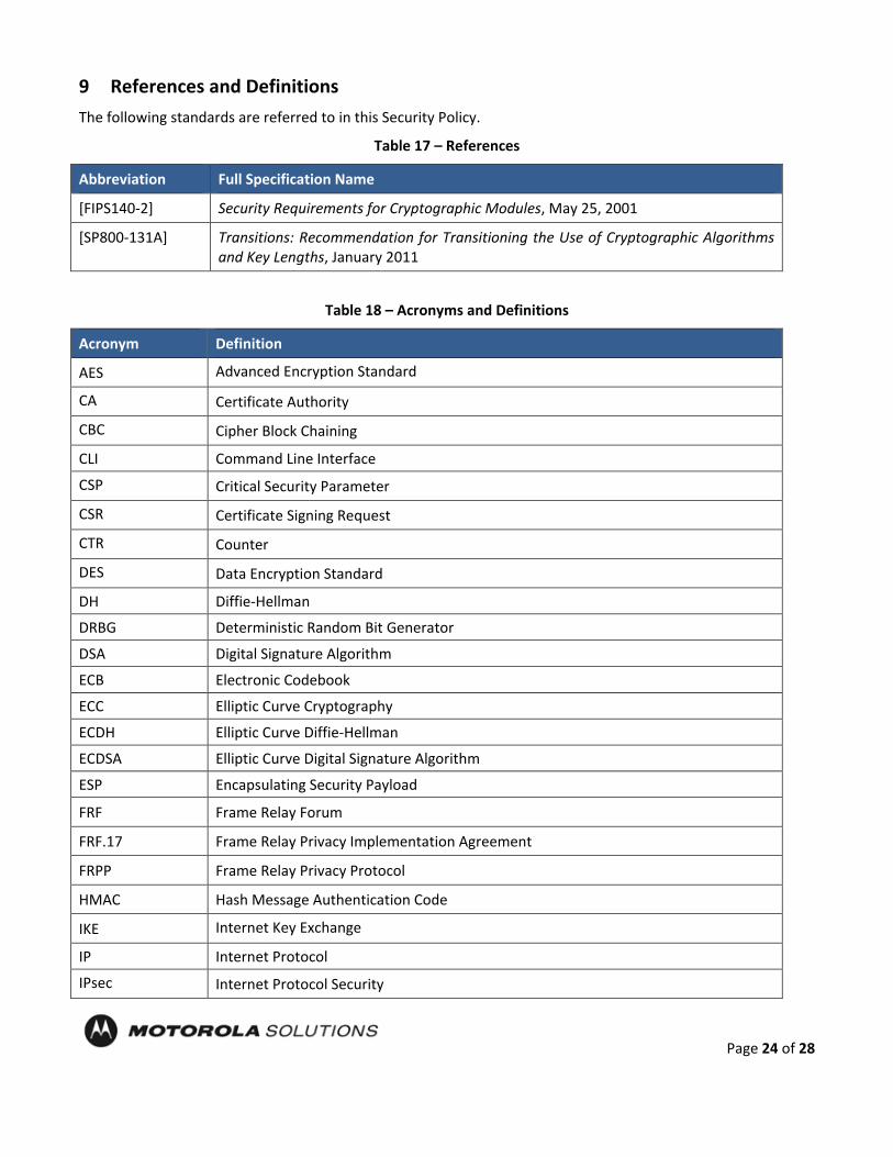
9 References and Definitions The following standards are referred to in this Security Policy.
Table 17 – References
Abbreviation Full Specification Name
[FIPS140-2] Security Requirements for Cryptographic Modules, May 25, 2001
[SP800-131A] Transitions: Recommendation for Transitioning the Use of Cryptographic Algorithms and Key Lengths, January 2011
Table 18 – Acronyms and Definitions
Acronym Definition
AES Advanced Encryption Standard
CA Certificate Authority
CBC Cipher Block Chaining
CLI Command Line Interface
CSP Critical Security Parameter
CSR Certificate Signing Request
CTR Counter
DES Data Encryption Standard
DH Diffie-Hellman
DRBG Deterministic Random Bit Generator
DSA Digital Signature Algorithm
ECB Electronic Codebook
ECC Elliptic Curve Cryptography
ECDH Elliptic Curve Diffie-Hellman
ECDSA Elliptic Curve Digital Signature Algorithm
ESP Encapsulating Security Payload
FRF Frame Relay Forum
FRF.17 Frame Relay Privacy Implementation Agreement
FRPP Frame Relay Privacy Protocol
HMAC Hash Message Authentication Code
IKE Internet Key Exchange
IP Internet Protocol
IPsec Internet Protocol Security

Page 25 of 28
Acronym Definition
KAS Key Agreement Scheme
KAT Known Answer Test
KDF Key Derivation Function
KEK Key Encrypting Key
MNR Motorola Network Router
NDRNG Non-Deterministic Random Number Generator
OSPF Open Shortest Path First
PFS Perfect Forward Secrecy
PIM Protocol Independent Multicast
PKI Public Key Infrastructure
PSK Pre-Shared Key
RNG Random Number Generator
RSA Rivest, Shamir and Adleman
SHA Secure Hash Algorithm
SSH Secure Shell
SNMP Simple Network Management Protocol
Tanapa The part number that is built and stocked for customer orders
10 GGM 8000 GATEWAY TAMPER EVIDENCE LABEL INSTALLATION INSTRUCTIONS Follow these steps to install tamper evidence labels on the GGM 8000 gateway: The surface to which the labels will be attached must be at a temperature of at least +10°C (+50°F), and the surface must be clean and dry. Clean any grease, dirt, oil, or adhesive residue from the areas to which the labels are to be attached before applying the tamper evidence labels. If you are replacing tamper evidence labels (after a repair, for example), remove the old labels and any adhesive residue with isopropyl alcohol (99% concentration) prior to applying the new labels.
1. Wipe the surface clean with isopropyl alcohol (99% concentration) to remove surface
contaminants. Please note that using a solution with an isopropyl alcohol concentration less than 99% is not acceptable.
2. Do not allow excess alcohol to air dry. Use a clean paper towel or cotton cloth to completely
remove any excess alcohol, thereby removing any residual contaminants.
3. Apply tamper evidence labels 1, 2, and 3 (optional) to secure the GGM 8000 base module and blank filler panel on the front of the chassis.
Do not push labels 1, 2, and 3 all the way up under the top cover overhang or tuck the labels into the

Page 26 of 28
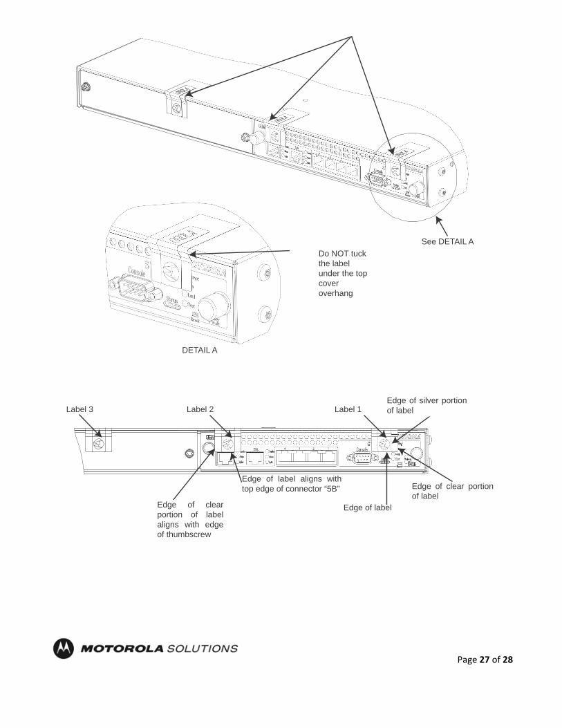
Figure 2 – Applying Tamper Evidence Labels 1, 2, and 3 to Secure the GGM 8000 Base Unit (Base Module and Blank Filler Panel in Expansion Module Slot
gap between the front panel and the top cover overhang. As shown in Detail A in Figure 2 the labels should come out at approximately a 45 degree angle from where they are affixed to the front panel to where they wrap around and over the top cover.
a. Remove the Kraft liner from the back of label 1 and attach the label as illustrated in Figure
2 (GGM 8000 base unit (base module and blank filler panel)) Center the silver portion of the label between the rightmost cooling hole and the Encrypt, Run, Load, and Test LEDs, with the Motorola logo on the label lined up with the top of the Load LED. Starting from the short edge of the label that is positioned on the front panel, affix the label by applying pressure while pushing the label up the front panel and onto the top cover.
b. Remove the Kraft liner from the back of label 2 and attach the label as illustrated in Figure
2 (GGM 8000 base unit (base module and blank filler panel)). Position the Motorola logo edge of the label directly above the top edge of connector “5B” with the left edge of the clear portion of the label aligned with the edge of the thumbscrew. Starting from the short edge of the label that is positioned on the front panel, affix the label by applying pressure while pushing the label up the front panel and onto the top cover.
Note: Label 3 is optional and is not required for a FIPS-approved configuration. The additional tamper evidence label provides additional tamper evidence beyond the module cryptographic boundary.
c. Remove the Kraft liner from the back of label 3 and attach the label as illustrated in
Figure 2.
Position the label approximately in the middle of the blank panel with the perforation between the “T” and the “O” aligned with the edge of the top cover. Starting from the short edge of the label that is positioned on the front panel, affix the label by applying pressure while pushing the label up the front panel and onto the top cover.
d. Rub the labels on the front and top of the chassis for two (2) seconds to ensure that the
labels have adhered.
If labels 1, 2, and 3 are applied correctly, the perforation between the “T” and the “O” aligns with the edge of the cover
Page 27 of 28
See DET AIL A
Label 2
Edge of label aligns with
top edge of connector "5B"
Do NOT tuck the label under the top cover overhang
See DETAIL A
DETAIL A
Label 3
Label 2
Label 1
Edge of silver portion of label
Edge of clear portion of label aligns with edge of thumbscrew
Edge of label aligns with top edge of connector “5B”
Edge of label
Edge of clear portion of label

Page 28 of 28
4. Apply tamper evidence label 4 to secure the GGM 8000 power supply module on the rear of the chassis.
Note: These instructions apply to a GGM 8000 equipped with either an AC or a DC power supply module.
a. Remove the Kraft liner from the back of the label and position the label as illustrated
in Figure 2.
Note: Figure 2 illustrates the label placement for the AC power supply module. The label placement for the DC power supply module is the same.
Position the Motorola logo edge of the label directly above the mounting screw, with the right edge of the silver portion of the label aligned with the right edge of the power supply module. Starting from the short edge of the label that is positioned on the rear panel, affix the label by applying pressure while pushing the label up the rear panel and onto the top cover.
b. Rub the label on the top and rear of the chassis for 2 seconds to ensure that the label
has adhered. 5. Secure the unit in a restricted area. 6. Allow the applied labels to cure for at least 4 hours; do not touch the labels during this time. If you need to re-apply the tamper evidence labels to the GGM 8000, repeat steps 1-6.