Motorized Test Stand...Reference and Registration 1 TCM Operation Manual Reference and Registration...
20
TCM Series Operation Manual Motorized Test Stand Model 100 and 350
Transcript of Motorized Test Stand...Reference and Registration 1 TCM Operation Manual Reference and Registration...
TCM Series Operation ManualMotorized Test Stand
Model 100 and 350
Contents
Reference and Registration . . . . . . . . . . . . . . . . . . . . . . . . . . . . . . . . . . . . . . 1
Welcome . . . . . . . . . . . . . . . . . . . . . . . . . . . . . . . . . . . . . . . . . . . . . . . . . . . . . . . . . . . . . . . 1
Warnings . . . . . . . . . . . . . . . . . . . . . . . . . . . . . . . . . . . . . . . . . . . . . . . . . . . . . . . . . . . . . . . 2
Overview . . . . . . . . . . . . . . . . . . . . . . . . . . . . . . . . . . . . . . . . . . . . . . . . . . . . . . . . . . . . . . . 3
Introduction . . . . . . . . . . . . . . . . . . . . . . . . . . . . . . . . . . . . . . . . . . . . . . . . . . . . . . . . . . . . 3
Parts Included with the TCM Series . . . . . . . . . . . . . . . . . . . . . . . . . . . . . . . . . . . . 3
Chatillon Force Gauges . . . . . . . . . . . . . . . . . . . . . . . . . . . . . . . . . . . . . . . . . . . . . . . 3
Front Panel Buttons . . . . . . . . . . . . . . . . . . . . . . . . . . . . . . . . . . . . . . . . . . . . . . . . . . . . . 4
Start/Stop . . . . . . . . . . . . . . . . . . . . . . . . . . . . . . . . . . . . . . . . . . . . . . . . . . . . . . . . . . . 4
Return to Zero (RTZ) . . . . . . . . . . . . . . . . . . . . . . . . . . . . . . . . . . . . . . . . . . . . . . . . . . 4
Jog Up . . . . . . . . . . . . . . . . . . . . . . . . . . . . . . . . . . . . . . . . . . . . . . . . . . . . . . . . . . . . . . 5
Jog Down . . . . . . . . . . . . . . . . . . . . . . . . . . . . . . . . . . . . . . . . . . . . . . . . . . . . . . . . . . . 5
Zero . . . . . . . . . . . . . . . . . . . . . . . . . . . . . . . . . . . . . . . . . . . . . . . . . . . . . . . . . . . . . . . . . 5
Speed Up . . . . . . . . . . . . . . . . . . . . . . . . . . . . . . . . . . . . . . . . . . . . . . . . . . . . . . . . . . . . 5
Speed Down . . . . . . . . . . . . . . . . . . . . . . . . . . . . . . . . . . . . . . . . . . . . . . . . . . . . . . . . . 5
Mode . . . . . . . . . . . . . . . . . . . . . . . . . . . . . . . . . . . . . . . . . . . . . . . . . . . . . . . . . . . . . . . 6
Front Panel Indicators and Display . . . . . . . . . . . . . . . . . . . . . . . . . . . . . . . . . . . . . . . 6
Speed Display . . . . . . . . . . . . . . . . . . . . . . . . . . . . . . . . . . . . . . . . . . . . . . . . . . . . . . . 6
Millimeters per Minute . . . . . . . . . . . . . . . . . . . . . . . . . . . . . . . . . . . . . . . . . . . . . . . 7
Inches per Minute . . . . . . . . . . . . . . . . . . . . . . . . . . . . . . . . . . . . . . . . . . . . . . . . . . . . 7
Compression . . . . . . . . . . . . . . . . . . . . . . . . . . . . . . . . . . . . . . . . . . . . . . . . . . . . . . . . 7
Tension . . . . . . . . . . . . . . . . . . . . . . . . . . . . . . . . . . . . . . . . . . . . . . . . . . . . . . . . . . . . . . 7
Modes of Operation . . . . . . . . . . . . . . . . . . . . . . . . . . . . . . . . . . . . . . . . . . . . . . . . . . . . . 7
Compression-Standard . . . . . . . . . . . . . . . . . . . . . . . . . . . . . . . . . . . . . . . . . . . . . . . 7
Tension-Standard . . . . . . . . . . . . . . . . . . . . . . . . . . . . . . . . . . . . . . . . . . . . . . . . . . . . 7
Compression-Cycle . . . . . . . . . . . . . . . . . . . . . . . . . . . . . . . . . . . . . . . . . . . . . . . . . . 8
Tension-Cycle . . . . . . . . . . . . . . . . . . . . . . . . . . . . . . . . . . . . . . . . . . . . . . . . . . . . . . . . 8
Rear Panel Ports and Connections . . . . . . . . . . . . . . . . . . . . . . . . . . . . . . . . . . . . . . . . 9
Communication Port . . . . . . . . . . . . . . . . . . . . . . . . . . . . . . . . . . . . . . . . . . . . . . . . . 9
USB Port . . . . . . . . . . . . . . . . . . . . . . . . . . . . . . . . . . . . . . . . . . . . . . . . . . . . . . . . . . . . . 9
Digital Force Gauge (DFG) Port . . . . . . . . . . . . . . . . . . . . . . . . . . . . . . . . . . . . . . . 9
Main Power Switch . . . . . . . . . . . . . . . . . . . . . . . . . . . . . . . . . . . . . . . . . . . . . . . . . . 10
Main Power Fuse . . . . . . . . . . . . . . . . . . . . . . . . . . . . . . . . . . . . . . . . . . . . . . . . . . . . 10
IEC Power Cord Connection . . . . . . . . . . . . . . . . . . . . . . . . . . . . . . . . . . . . . . . . . 10
Remote Foot Switch . . . . . . . . . . . . . . . . . . . . . . . . . . . . . . . . . . . . . . . . . . . . . . . . . 10
Emergency Switch . . . . . . . . . . . . . . . . . . . . . . . . . . . . . . . . . . . . . . . . . . . . . . . . . . . . . 11
Fault and Error Codes . . . . . . . . . . . . . . . . . . . . . . . . . . . . . . . . . . . . . . . . . . . . . . . . . . . 11
Securing the TCM to a Workbench . . . . . . . . . . . . . . . . . . . . . . . . . . . . . . . . . . . . . . 12
Specifications . . . . . . . . . . . . . . . . . . . . . . . . . . . . . . . . . . . . . . . . . . . . . . . . . . . . . . . 13
TCM Dimensions . . . . . . . . . . . . . . . . . . . . . . . . . . . . . . . . . . . . . . . . . . . . . . . . . . . . . . . 14
TCM Mounting Plate Options . . . . . . . . . . . . . . . . . . . . . . . . . . . . . . . . . . . . . . . . . . . 15
Standard Mounting Plate . . . . . . . . . . . . . . . . . . . . . . . . . . . . . . . . . . . . . . . . . . . . 15
Optional Multi-Thread Plate Kit (p/n SPK-TCM-005) . . . . . . . . . . . . . . . . . . . . . . 15
Support . . . . . . . . . . . . . . . . . . . . . . . . . . . . . . . . . . . . . . . . . . . . . . . . . . . . . . . . . . . . . . . 16
Optional Accessories . . . . . . . . . . . . . . . . . . . . . . . . . . . . . . . . . . . . . . . . . . . . . . . . . . . 16
Contact Us . . . . . . . . . . . . . . . . . . . . . . . . . . . . . . . . . . . . . . . . . . . . . . . . . . . . . . . . . . . . . 17
Returning product to AMETEK . . . . . . . . . . . . . . . . . . . . . . . . . . . . . . . . . . . . . . . . . . 17
Warranty . . . . . . . . . . . . . . . . . . . . . . . . . . . . . . . . . . . . . . . . . . . . . . . . . . . . . . . . . . . . . . 17
Reference and Registration 1
TCM Operation Manual
Reference and Registration
����� WELCOME
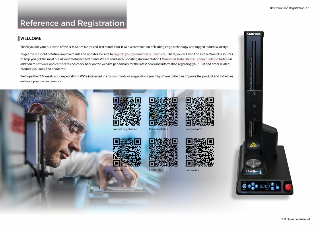
Thank you for your purchase of the TCM Series Motorized Test Stand. Your TCM is a combination of leading edge technology and rugged industrial design.
To get the most out of future improvements and updates, be sure to register your product on our website. There, you will also find a collection of resources
to help you get the most out of your motorized test stand. We are constantly updating documentation ( Manuals & Data Sheets; Product Release Notes ) in
addition to software and certificates. So check back on the website periodically for the latest news and information regarding your TCM and other related
products you may find of interest.
We hope the TCM meets your expectations. We’re interested in any comments or suggestions you might have to help us improve the product and to help us
enhance your user experience.
Product Registration
Software
Documentation
Certificates
Release Notes
Comments
Warnings 2
TCM Operation Manual
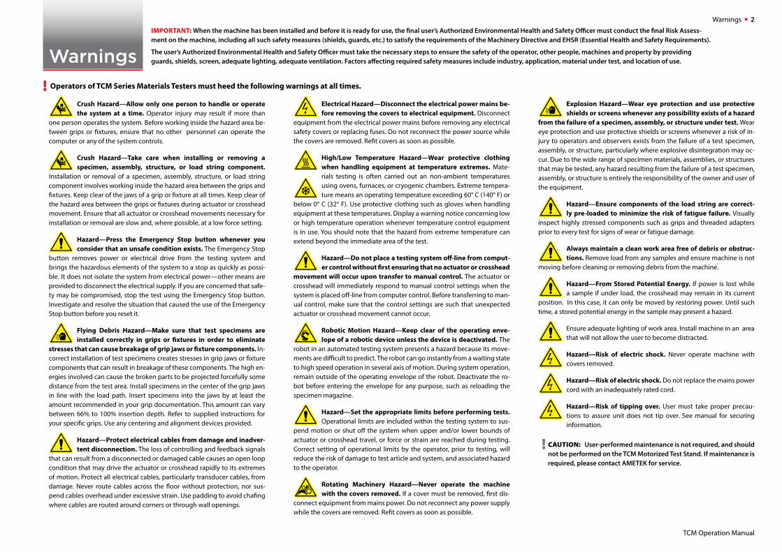
Warnings ! Operators of TCM Series Materials Testers must heed the following warnings at all times.
Crush Hazard—Allow only one person to handle or operate the system at a time. Operator injury may result if more than
one person operates the system. Before working inside the hazard area be-tween grips or fixtures, ensure that no other personnel can operate the computer or any of the system controls.
Crush Hazard—Take care when installing or removing a specimen, assembly, structure, or load string component.
Installation or removal of a specimen, assembly, structure, or load string component involves working inside the hazard area between the grips and fixtures. Keep clear of the jaws of a grip or fixture at all times. Keep clear of the hazard area between the grips or fixtures during actuator or crosshead movement. Ensure that all actuator or crosshead movements necessary for installation or removal are slow and, where possible, at a low force setting.
Hazard—Press the Emergency Stop button whenever you consider that an unsafe condition exists. The Emergency Stop
button removes power or electrical drive from the testing system and brings the hazardous elements of the system to a stop as quickly as possi-ble. It does not isolate the system from electrical power—other means are provided to disconnect the electrical supply. If you are concerned that safe-ty may be compromised, stop the test using the Emergency Stop button. Investigate and resolve the situation that caused the use of the Emergency Stop button before you reset it.
Flying Debris Hazard—Make sure that test specimens are installed correctly in grips or fixtures in order to eliminate
stresses that can cause breakage of grip jaws or fixture components. In-correct installation of test specimens creates stresses in grip jaws or fixture components that can result in breakage of these components. The high en-ergies involved can cause the broken parts to be projected forcefully some distance from the test area. Install specimens in the center of the grip jaws in line with the load path. Insert specimens into the jaws by at least the amount recommended in your grip documentation. This amount can vary between 66% to 100% insertion depth. Refer to supplied instructions for your specific grips. Use any centering and alignment devices provided.
Hazard—Protect electrical cables from damage and inadver-tent disconnection. The loss of controlling and feedback signals
that can result from a disconnected or damaged cable causes an open loop condition that may drive the actuator or crosshead rapidly to its extremes of motion. Protect all electrical cables, particularly transducer cables, from damage. Never route cables across the floor without protection, nor sus-pend cables overhead under excessive strain. Use padding to avoid chafing where cables are routed around corners or through wall openings.
Electrical Hazard—Disconnect the electrical power mains be-fore removing the covers to electrical equipment. Disconnect
equipment from the electrical power mains before removing any electrical safety covers or replacing fuses. Do not reconnect the power source while the covers are removed. Refit covers as soon as possible.
High/Low Temperature Hazard—Wear protective clothing when handling equipment at temperature extremes. Mate-rials testing is often carried out an non-ambient temperatures using ovens, furnaces, or cryogenic chambers. Extreme tempera-ture means an operating temperature exceeding 60° C (140° F) or
below 0° C (32° F). Use protective clothing such as gloves when handling equipment at these temperatures. Display a warning notice concerning low or high temperature operation whenever temperature control equipment is in use. You should note that the hazard from extreme temperature can extend beyond the immediate area of the test.
Hazard—Do not place a testing system off-line from comput-er control without first ensuring that no actuator or crosshead
movement will occur upon transfer to manual control. The actuator or crosshead will immediately respond to manual control settings when the system is placed off-line from computer control. Before transferring to man-ual control, make sure that the control settings are such that unexpected actuator or crosshead movement cannot occur.
Robotic Motion Hazard—Keep clear of the operating enve-lope of a robotic device unless the device is deactivated. The
robot in an automated testing system presents a hazard because its move-ments are difficult to predict. The robot can go instantly from a waiting state to high speed operation in several axis of motion. During system operation, remain outside of the operating envelope of the robot. Deactivate the ro-bot before entering the envelope for any purpose, such as reloading the specimen magazine.
Hazard—Set the appropriate limits before performing tests. Operational limits are included within the testing system to sus-
pend motion or shut off the system when upper and/or lower bounds of actuator or crosshead travel, or force or strain are reached during testing. Correct setting of operational limits by the operator, prior to testing, will reduce the risk of damage to test article and system, and associated hazard to the operator.
Rotating Machinery Hazard—Never operate the machine with the covers removed. If a cover must be removed, first dis-
connect equipment from mains power. Do not reconnect any power supply while the covers are removed. Refit covers as soon as possible.
Explosion Hazard—Wear eye protection and use protective shields or screens whenever any possibility exists of a hazard
from the failure of a specimen, assembly, or structure under test. Wear eye protection and use protective shields or screens whenever a risk of in-jury to operators and observers exists from the failure of a test specimen, assembly, or structure, particularly where explosive disintegration may oc-cur. Due to the wide range of specimen materials, assemblies, or structures that may be tested, any hazard resulting from the failure of a test specimen, assembly, or structure is entirely the responsibility of the owner and user of the equipment.
Hazard—Ensure components of the load string are correct-ly pre-loaded to minimize the risk of fatigue failure. Visually
inspect highly stressed components such as grips and threaded adapters prior to every test for signs of wear or fatigue damage.
Always maintain a clean work area free of debris or obstruc-tions. Remove load from any samples and ensure machine is not
moving before cleaning or removing debris from the machine.
Hazard—From Stored Potential Energy. If power is lost while a sample if under load, the crosshead may remain in its current
position. In this case, it can only be moved by restoring power. Until such time, a stored potential energy in the sample may present a hazard.
Ensure adequate lighting of work area. Install machine in an area that will not allow the user to become distracted.
Hazard—Risk of electric shock. Never operate machine with covers removed.
Hazard—Risk of electric shock. Do not replace the mains power cord with an inadequately rated cord.
Hazard—Risk of tipping over. User must take proper precau-tions to assure unit does not tip over. See manual for securing information.
! CAUTION: User-performed maintenance is not required, and should not be performed on the TCM Motorized Test Stand. If maintenance is required, please contact AMETEK for service.
IMPORTANT: When the machine has been installed and before it is ready for use, the final user’s Authorized Environmental Health and Safety Officer must conduct the final Risk Assess-ment on the machine, including all such safety measures (shields, guards, etc.) to satisfy the requirements of the Machinery Directive and EHSR (Essential Health and Safety Requirements).
The user’s Authorized Environmental Health and Safety Officer must take the necessary steps to ensure the safety of the operator, other people, machines and property by providing guards, shields, screen, adequate lighting, adequate ventilation. Factors affecting required safety measures include industry, application, material under test, and location of use.
Overview 3
TCM Operation Manual
Overview
����� INTRODUCTION
Two CHATILLON® TCM Series motorized test stands are available and covered by this Operation Manual:
• TCM100 Series (100 lbf, 500 N)
• TCM350 Series (350 lbf, 2500 N)
TCM Series motorized testers are designed to be use with Chatillon DF Series digital force gauges.
The TCM Series has a compact design, making it ideal for the laboratory or production environment. The machine is designed for benchtop installations.
These testers are designed to operate in a vertical orientation
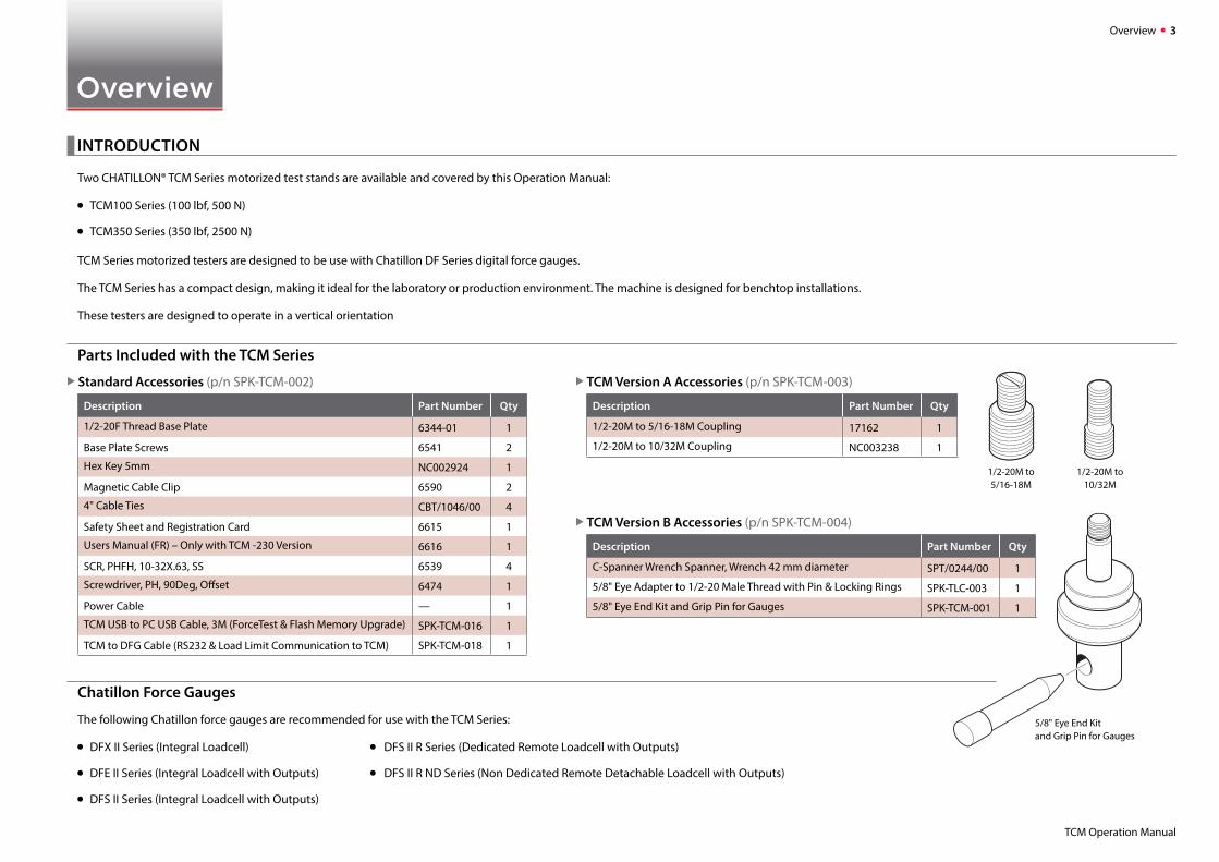
Parts Included with the TCM Series
X Standard Accessories (p/n SPK-TCM-002)
Description Part Number Qty
1/2-20F Thread Base Plate 6344-01 1
Base Plate Screws 6541 2
Hex Key 5mm NC002924 1
Magnetic Cable Clip 6590 2
4" Cable Ties CBT/1046/00 4
Safety Sheet and Registration Card 6615 1
Users Manual (FR) – Only with TCM -230 Version 6616 1
SCR, PHFH, 10-32X.63, SS 6539 4
Screwdriver, PH, 90Deg, Offset 6474 1
Power Cable — 1
TCM USB to PC USB Cable, 3M (ForceTest & Flash Memory Upgrade) SPK-TCM-016 1
TCM to DFG Cable (RS232 & Load Limit Communication to TCM) SPK-TCM-018 1
X TCM Version A Accessories (p/n SPK-TCM-003)
Description Part Number Qty
1/2-20M to 5/16-18M Coupling 17162 1
1/2-20M to 10/32M Coupling NC003238 1
X TCM Version B Accessories (p/n SPK-TCM-004)
Description Part Number Qty
C-Spanner Wrench Spanner, Wrench 42 mm diameter SPT/0244/00 1
5/8" Eye Adapter to 1/2-20 Male Thread with Pin & Locking Rings SPK-TLC-003 1
5/8" Eye End Kit and Grip Pin for Gauges SPK-TCM-001 1
1/2-20M to 5/16-18M
1/2-20M to 10/32M
5/8" Eye End Kit and Grip Pin for Gauges
Chatillon Force Gauges
The following Chatillon force gauges are recommended for use with the TCM Series:
• DFX II Series (Integral Loadcell) • DFS II R Series (Dedicated Remote Loadcell with Outputs)
• DFE II Series (Integral Loadcell with Outputs) • DFS II R ND Series (Non Dedicated Remote Detachable Loadcell with Outputs)
• DFS II Series (Integral Loadcell with Outputs)
Overview 4
TCM Operation Manual
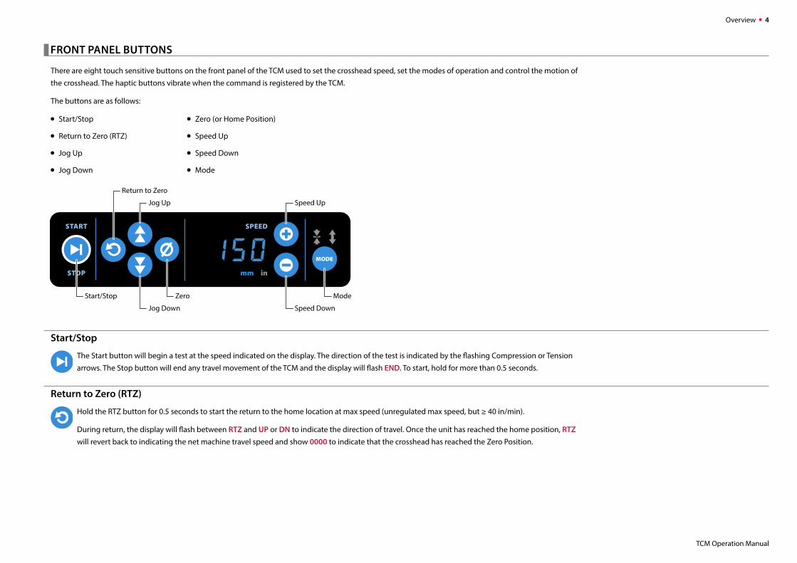
����� FRONT PANEL BUTTONS
There are eight touch sensitive buttons on the front panel of the TCM used to set the crosshead speed, set the modes of operation and control the motion of
the crosshead. The haptic buttons vibrate when the command is registered by the TCM.
The buttons are as follows:
• Start/Stop
• Return to Zero (RTZ)
• Jog Up
• Jog Down
Start/Stop
The Start button will begin a test at the speed indicated on the display. The direction of the test is indicated by the flashing Compression or Tension
arrows. The Stop button will end any travel movement of the TCM and the display will flash END. To start, hold for more than 0.5 seconds.
Return to Zero (RTZ)
Hold the RTZ button for 0.5 seconds to start the return to the home location at max speed (unregulated max speed, but ≥ 40 in/min).
During return, the display will flash between RTZ and UP or DN to indicate the direction of travel. Once the unit has reached the home position, RTZ
will revert back to indicating the net machine travel speed and show 0000 to indicate that the crosshead has reached the Zero Position.
• Zero (or Home Position)
• Speed Up
• Speed Down
• Mode
MODE
SPEED
STOP
START
Return to Zero
Jog Up Speed Up
Jog Down Speed Down
Zero ModeStart/Stop
Overview 5
TCM Operation Manual
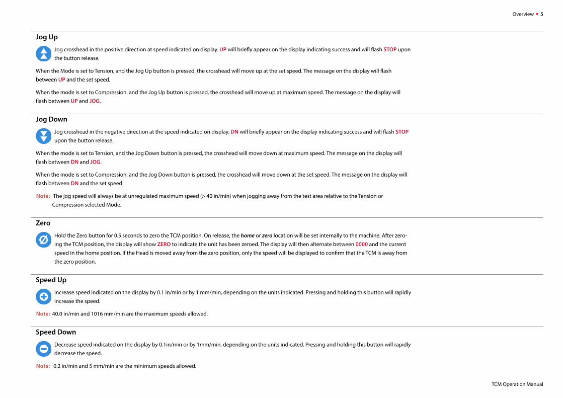
Jog Up
Jog crosshead in the positive direction at speed indicated on display. UP will briefly appear on the display indicating success and will flash STOP upon
the button release.
When the Mode is set to Tension, and the Jog Up button is pressed, the crosshead will move up at the set speed. The message on the display will flash
between UP and the set speed.
When the mode is set to Compression, and the Jog Up button is pressed, the crosshead will move up at maximum speed. The message on the display will
flash between UP and JOG.
Jog Down
Jog crosshead in the negative direction at the speed indicated on display. DN will briefly appear on the display indicating success and will flash STOP
upon the button release.
When the mode is set to Tension, and the Jog Down button is pressed, the crosshead will move down at maximum speed. The message on the display will
flash between DN and JOG.
When the mode is set to Compression, and the Jog Down button is pressed, the crosshead will move down at the set speed. The message on the display will
flash between DN and the set speed.
Note: The jog speed will always be at unregulated maximum speed (> 40 in/min) when jogging away from the test area relative to the Tension or
Compression selected Mode.
Zero
Hold the Zero button for 0.5 seconds to zero the TCM position. On release, the home or zero location will be set internally to the machine. After zero-
ing the TCM position, the display will show ZERO to indicate the unit has been zeroed. The display will then alternate between 0000 and the current
speed in the home position. If the Head is moved away from the zero position, only the speed will be displayed to confirm that the TCM is away from
the zero position.
Speed Up
Increase speed indicated on the display by 0.1 in/min or by 1 mm/min, depending on the units indicated. Pressing and holding this button will rapidly
increase the speed.
Note: 40.0 in/min and 1016 mm/min are the maximum speeds allowed.
Speed Down
Decrease speed indicated on the display by 0.1in/min or by 1mm/min, depending on the units indicated. Pressing and holding this button will rapidly
decrease the speed.
Note: 0.2 in/min and 5 mm/min are the minimum speeds allowed.
Overview 6
TCM Operation Manual
Mode
The Mode button is used for two purposes. It sets the mode of crosshead operation for the TCM and it is used to set the crosshead
speed units.
On <1s duration button press, switch between the following modes:
Tension Compression Cycle / Tension Cycle / Compression Tension.
Note: The mode selection will continue to repeat after the Cycle / Compression has been reached.
Holding the button for 5 or more seconds will toggle units between: in mm in
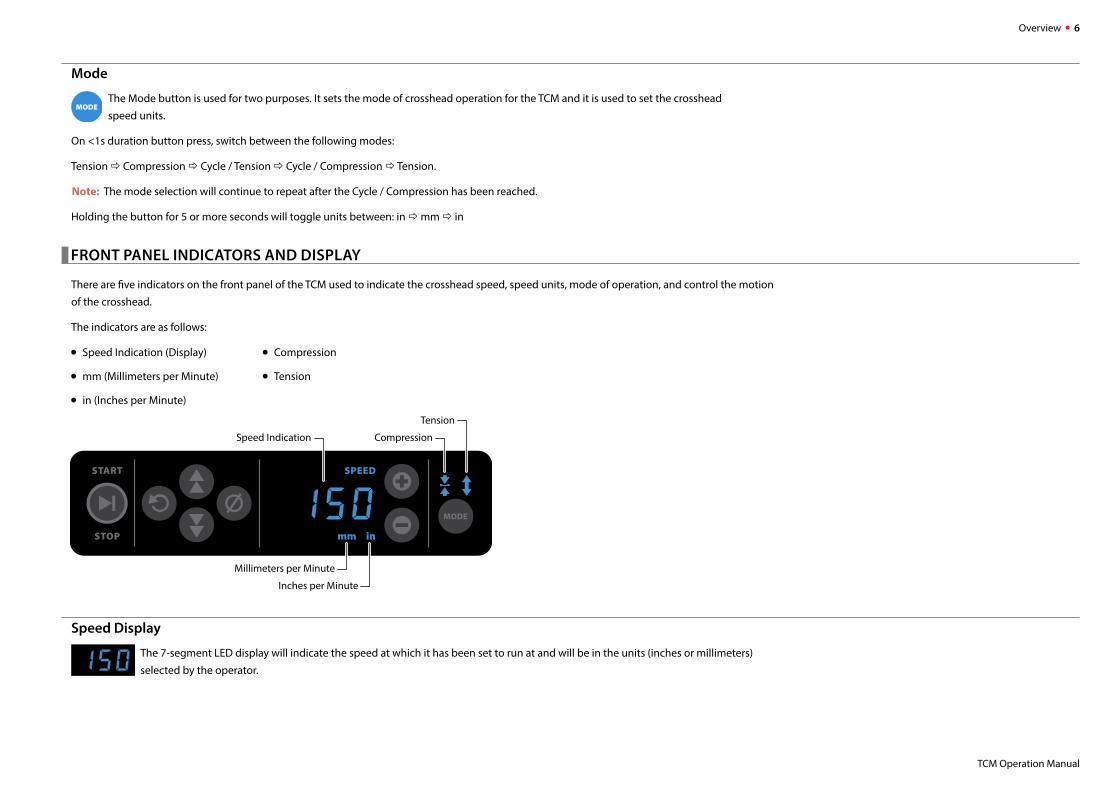
����� FRONT PANEL INDICATORS AND DISPLAY
There are five indicators on the front panel of the TCM used to indicate the crosshead speed, speed units, mode of operation, and control the motion
of the crosshead.
The indicators are as follows:
• Speed Indication (Display)
• mm (Millimeters per Minute)
• in (Inches per Minute)
Speed Display
The 7-segment LED display will indicate the speed at which it has been set to run at and will be in the units (inches or millimeters)
selected by the operator.
• Compression
• Tension
MODE
SPEED
STOP
START
Tension
CompressionSpeed Indication
Inches per Minute
Millimeters per Minute
Overview 7
TCM Operation Manual
Millimeters per Minute
When the mm indicator is illuminated, the units for the crosshead speed (as indicated on the Speed Indication Display) will be in millimeters
per minute.
Inches per Minute
When the in indicator is illuminated, the units for the crosshead speed (as indicated on the Speed Indication Display) will be in inches
per minute.
Compression
When the compression arrow indicator is illuminated, the crosshead will move in the compression direction when the Start/Stop button is
depressed. (See Modes of Operation below).
Tension
When this the Tension arrow indicator is illuminated, the crosshead will move in the tension direction when the Start/Stop button is depressed.
(See Modes of Operation below).
����� MODES OF OPERATIONNote: In all modes, when a DFG is connected to the TCM and a DFG set Force Limit is reached, the TCM will stop and the Message “Load” will be displayed.
Compression-Standard
When only the Compression indicator is illuminated, this indicates the Compression-Standard mode of operation. In this mode, the crosshead will
move in the compression direction (at the speed indicated on the display) when instructed to do so by pressing the Start/Stop button. It will automat-
ically continue in this direction until it reaches the adjustable limit switch position. If the mechanical limit switch is reached, the display will show BOT and the
Set Speed to indicate that the lower (bottom) travel limit switch has been reached. Further, if a force gauge was set to XMIT LIMIT (transmit a force limit), the
TCM will stop when a low signal is sent over the serial port. The XMIT will stop the TCM only when connected to the Test Stand using the XMIT cable (SPK-
TCM-018) into the DFG Port.
When moving in the compression direction, the display will flash alternatively between DN and the current speed.
Tension-Standard
When only the Tension indicator is illuminated, this indicates the Tension-Standard mode of operation. In this mode, the crosshead will move in the
tension direction (at the speed indicated on the display) when instructed to do so by pressing the Start/Stop button. It will automatically continue in this
direction until it reaches the adjustable limit switch position. If the mechanical limit switch is reached, the display will show TOP and the set speed to indicate
that the upper (top) travel limit switch has been reached. Further, if a force gauge was set to XMIT LIMIT (transmit a force limit), the TCM will stop when a high
signal is sent over the serial port. The XMIT will stop the TCM only when connected to the Test Stand using the XMIT cable (SPK-TCM-018) into the DFG Port.
When moving in the tension direction, the display will flash alternatively between UP and the current speed.
Overview 8
TCM Operation Manual
Compression-Cycle
When the Compression indicator is illuminated, and the Tension indicator is dimly lit, this indicates the Compression-Cycle mode of operation. In this
mode, the crosshead will move in the compression direction (at the speed indicated on the display) when instructed to do so by pressing the Start/
Stop button. It will automatically continue in this direction until it reaches the lower adjustable limit switch position, at which point it will change to the ten-
sion direction and continue until it reaches the upper adjustable limit switch position. Upon reaching the upper adjustable limit switch position, it will change
direction again and continue to cycle back and forth between the two limit switch positions. The Cycle mode can also be controlled by Force when setting the
Load Limits on the force gauge and connecting the force gauge to the TCM using cable SPK-TCM-018. When the crosshead is in motion for this mode, the Com-
pression indicator will flash the following messages during the cycle:
DN with the Cycle Count C001, C002…
then UP with the Cycle Count C001, C002.
The Maximum cycle count is 999.
Pressing the Start/Stop button again will stop the crosshead motion. Further, if a force gauge was set to XMIT LIMIT, the TCM will continue to cycle to both lim-
its when a low or high signal is sent to the DFG port. The XMIT will stop the TCM only when connected to the Test Stand using the XMIT cable into the DFG Port.
Tension-Cycle
When the Tension indicator is illuminated, and the Compression indicator is dimly lit, this indicates the Tension-Cycle mode of operation. In this mode,
the crosshead will move in the compression direction (at the speed indicated on the display) when instructed to do so by pressing the Start/Stop
button. It will automatically continue in this direction until it reaches the upper adjustable limit switch position, at which point it will change to the tension
direction and continue until it reaches the lower adjustable limit switch position. Upon reaching the lower adjustable limit switch position, it will change
direction again and continue to cycle back and forth between the two limit switch positions. The Cycle mode can also be controlled by Force when setting
the Load Limits on the force gauge and connecting the force gauge to the TCM using cable SPK-TCM-018. When the crosshead is in motion for this mode, the
Tension indicator will flash the following messages during the cycle:
UP with the Cycle Count C001, C002…
then DN with the Cycle Count C001, C002.
The Maximum cycle count is 999.
Pressing the Start/Stop button again will stop the crosshead motion. Further, if a force gauge was set to XMIT LIMIT, the TCM will continue to cycle to both lim-
its when a low or high signal is sent to the DFG port. The XMIT will stop the TCM only when connected to the Test Stand using the XMIT cable into the DFG Port.
Overview 9
TCM Operation Manual
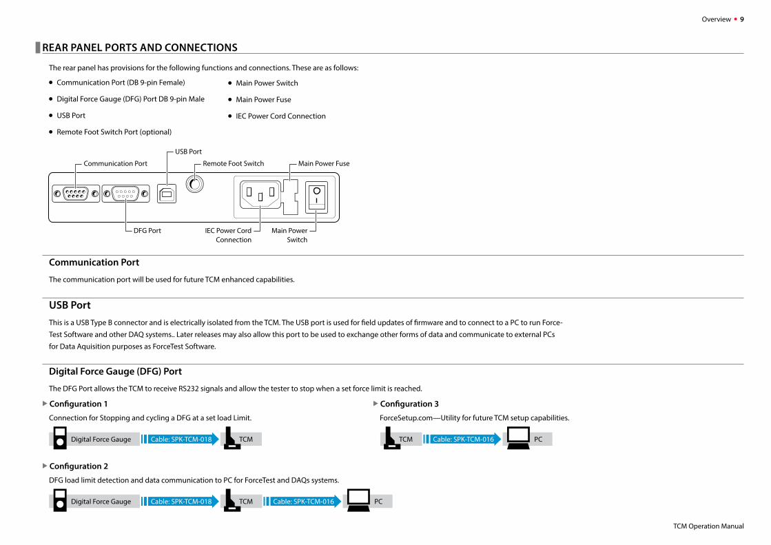
����� REAR PANEL PORTS AND CONNECTIONS
The rear panel has provisions for the following functions and connections. These are as follows:
• Communication Port (DB 9-pin Female)
• Digital Force Gauge (DFG) Port DB 9-pin Male
• USB Port
• Remote Foot Switch Port (optional)
Communication Port
The communication port will be used for future TCM enhanced capabilities.
USB PortThis is a USB Type B connector and is electrically isolated from the TCM. The USB port is used for field updates of firmware and to connect to a PC to run Force-
Test Software and other DAQ systems.. Later releases may also allow this port to be used to exchange other forms of data and communicate to external PCs
for Data Aquisition purposes as ForceTest Software.
Digital Force Gauge (DFG) Port
The DFG Port allows the TCM to receive RS232 signals and allow the tester to stop when a set force limit is reached.
X Configuration 1
Connection for Stopping and cycling a DFG at a set load Limit.
X Configuration 2
DFG load limit detection and data communication to PC for ForceTest and DAQs systems.
• Main Power Switch
• Main Power Fuse
• IEC Power Cord Connection
USB Port
Communication Port Remote Foot Switch Main Power Fuse
IEC Power CordConnection
DFG Port Main PowerSwitch
X Configuration 3
ForceSetup.com—Utility for future TCM setup capabilities.
Digital Force Gauge Cable: SPK-TCM-018 TCM
Digital Force Gauge Cable: SPK-TCM-018 Cable: SPK-TCM-016TCM PC
Cable: SPK-TCM-016TCM PC
Overview 10
TCM Operation Manual
Main Power Switch
This switch controls the main power to the TCM. Flip the switch next to the power cord inlet to turn the machine ON or OFF. When the machine is OFF, the
speed indicator display is not illuminated.
When first turning the machine OFF, you may note that it takes a few seconds for the speed indicator display to extinguish. This is normal and due to the
capacitors’ stored power that eventually discharges.
Main Power Fuse
The unit has a ceramic 5 mm x 20 mm 1.5 Amp slow-blow fuse. If for some reason the fuse needs to be replaced, use a fuse with same ratings as indicated.
To replace the fuse, follow these steps. First make sure the Main Power Switch is in the off position. Unplug the power cord from the outlet. Unplug the power
cord from the back of the TCM base. Now, using a screwdriver, pry open the fuse cover by inserting the blade of the screwdriver from the side the power cord
was in the back of the TCM and pry outward. Remove the old fuse and replace with the new one. Push fuse door back in place, plug the power cord back into
the TCM and then the power outlet. Turn on the Main Power Switch and check that the TCM powers up properly by observing the display and indicators on
the front panel of the TCM.
IEC Power Cord Connection
The input AC Mains Power requires no selection between 120 and 240 VAC as its power supply can automatically accommodate 100-240 VAC (50-60 Hz) nom-
inal. The appropriate IEC power cord was supplied with the TCM at time of order. To install the power cord, first plug the appropriate power cord into the TCM
and then into the power outlet. To remove the power cord, first unplug the power cord from the outlet and then remove the cord from the TCM.
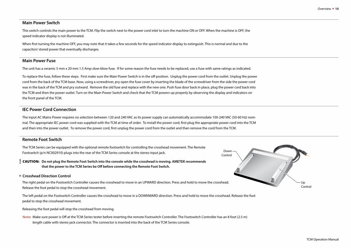
Remote Foot Switch
The TCM Series can be equipped with the optional remote footswitch for controlling the crosshead movement. The Remote
Footswitch (p/n NC002910) plugs into the rear of the TCM Series console at the stereo input jack.
! CAUTION: Do not plug the Remote Foot Switch into the console while the crosshead is moving. AMETEK recommends that the power to the TCM Series be Off before connecting the Remote Foot Switch.
X Crosshead Direction Control
The right pedal on the Footswitch Controller causes the crosshead to move in an UPWARD direction. Press and hold to move the crosshead.
Release the foot pedal to stop the crosshead movement.
The left pedal on the Footswitch Controller causes the crosshead to move in a DOWNWARD direction. Press and hold to move the crosshead. Release the foot
pedal to stop the crosshead movement.
Releasing the foot pedal will stop the crosshead from moving.
Note: Make sure power is Off at the TCM Series tester before inserting the remote Footswitch Controller. The Footswitch Controller has an 8 foot (2.5 m)
length cable with stereo jack connector. The connector is inserted into the back of the TCM Series console.
UpControl
DownControl
Overview 11
TCM Operation Manual
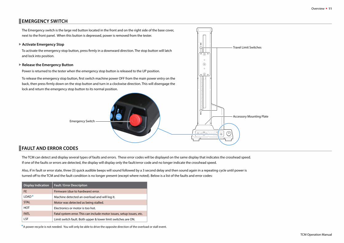
����� EMERGENCY SWITCH
The Emergency switch is the large red button located in the front and on the right side of the base cover,
next to the front panel. When this button is depressed, power is removed from the tester.
X Activate Emergency Stop
To activate the emergency stop button, press firmly in a downward direction. The stop button will latch
and lock into position.
X Release the Emergency Button
Power is returned to the tester when the emergency stop button is released to the UP position.
To release the emergency stop button, first switch machine power OFF from the main power entry on the
back, then press firmly down on the stop button and turn in a clockwise direction. This will disengage the
lock and return the emergency stop button to its normal position.
����� FAULT AND ERROR CODES
The TCM can detect and display several types of faults and errors. These error codes will be displayed on the same display that indicates the crosshead speed.
If one of the faults or errors are detected, the display will display only the fault/error code and no longer indicate the crosshead speed.
Also, if in fault or error state, three (3) quick audible beeps will sound followed by a 3 second delay and then sound again in a repeating cycle until power is
turned off to the TCM and the fault condition is no longer present (except where noted). Below is a list of the faults and error codes:
Display Indication Fault / Error Descripiton
FE Firmware (due to hardware) error.
LOAD * Machine detected an overload and will log it.
STAL Motor was detected as being stalled.
HOT Electronics or motor is too hot.
FATL Fatal system error. This can include motor issues, setup issues, etc.
LSF Limit switch fault. Both upper & lower limit switches are ON.
*A power recycle is not needed. You will only be able to drive the opposite direction of the overload or stall event.
MODE
SPEED
STOP
START
Emergency Switch
Travel Limit Switches
Accessory Mounting Plate
Overview 12
TCM Operation Manual
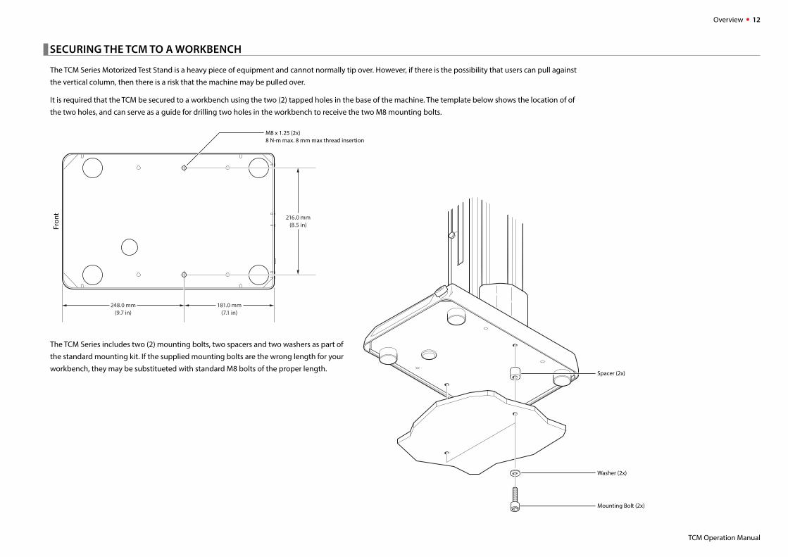
����� SECURING THE TCM TO A WORKBENCH
The TCM Series Motorized Test Stand is a heavy piece of equipment and cannot normally tip over. However, if there is the possibility that users can pull against
the vertical column, then there is a risk that the machine may be pulled over.
It is required that the TCM be secured to a workbench using the two (2) tapped holes in the base of the machine. The template below shows the location of of
the two holes, and can serve as a guide for drilling two holes in the workbench to receive the two M8 mounting bolts.
Fron
t
M8 x 1.25 (2x)8 N-m max. 8 mm max thread insertion
216.0 mm(8.5 in)
181.0 mm(7.1 in)
248.0 mm(9.7 in)
The TCM Series includes two (2) mounting bolts, two spacers and two washers as part of
the standard mounting kit. If the supplied mounting bolts are the wrong length for your
workbench, they may be substitueted with standard M8 bolts of the proper length.Spacer (2x)
Washer (2x)
Mounting Bolt (2x)
Specifications 13
TCM Operation Manual
Specifications
Load Capacity
TCM100 . . . . . . . . . . . . . 100 lbf (500 N)
TCM350 . . . . . . . . . . . . . 350 lbf (1500 N)
Travel
Standard . . . . . . . . . . . . 16 inches (~406 mm)
Extended . . . . . . . . . . . . 32 inches (~812 mm)
Speed
X Speed Range0.2 to 40.0 inches per minute (5 to 1016 millimeters per minute)
X Speed Accuracy± 0.1% of Set Speed (unloaded)
Frame Deflection
TCM100 . . . . . . . . . . . . . Less than 1 mm (0.04") at full load capacity
TCM350 . . . . . . . . . . . . . Less than 2 mm (0.06") at full load capacity
Measurement System
Chatillon DF Series Digital Force Gauge
Temperature
XOperating Temperature50 to 104° F (10 to 40° C)
Input Power
85-264 VAC at 47-63 Hz
Current . . . . . . . . . . . . . . 1 Amp Maximum
Relative Humidity
20 to 85% (non-condensing)
Weight
X Tester WeightStandard . . . . . . . . . . . . 57 lbs (25.9 kg) approximate
Extended . . . . . . . . . . . . 69 lbs (31.3 kg) approximate
X Shipping WeightStandard . . . . . . . . . . . . 197 lbs (90 kg)
Extended . . . . . . . . . . . . 209 lbs (94 kg)
Part Numbering System
Model / Force Crosshead Travel Height Power Mounting
100 lbf / 500 N . . . . TCM100 Standard 16" . . . . . . . . . . . . . . . S 115 VAC 60 Hz, US Power Cord . . . . . . . . . . . . . . . . . . . . . . . . -115 1/2-20F thread in base and 1/2-20M to 5/16-18M and 1/2-20M to 10-32M Couplings . . . -A
350 lbf / 1500 N . . . TCM350 Extended 32" . . . . . . . . . . . . . . E 230 VAC 50 Hz, UK and EU Power Cord . . . . . . . . . . . . . . . . -230 1/2-20F thread in base and 5/8” Eye End Adapter Kit for base and DFG . . . . . . . . . . . . . . . . . -B
230 VAC 50 Hz, China & Australia Power Cord . . . -230CNAU
SAMPLE PART NUMBERS
TCM100S-115-A . . . . . . . 100 lbf/400 N unit with standard 16" crosshead travel height, 115 VAC 60 Hz US power cord, 1/2-20F thread in base and 1/2-20M to 5/16-18M and 1/2-20M to 10-32M couplings.
TCM350E-230-B . . . . . . . 350 lbf/1500 N unit with extended 32” crosshead travel height, 230 VAC 50 Hz UK and EU power cord, 1/2-20F thread in base, and 5/8” Eye End Adapters for the base and DFG.
Specifications 14
TCM Operation Manual
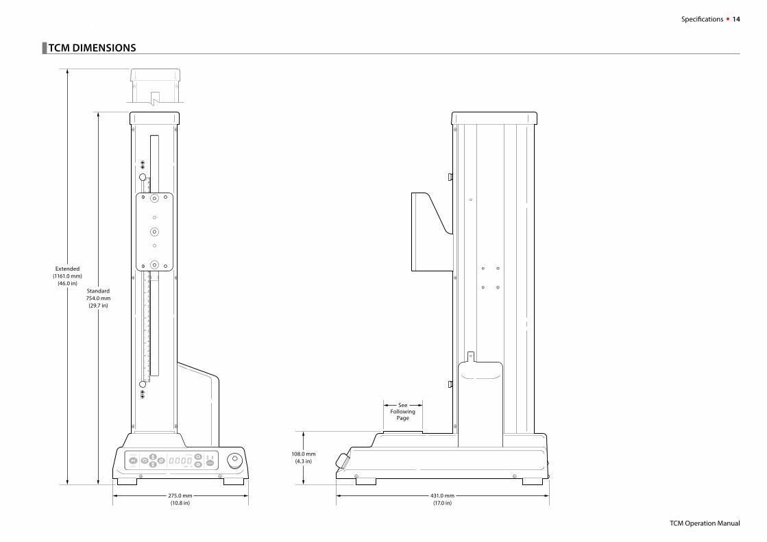
����� TCM DIMENSIONS
MODE
SPEED
STOP
START
Standard754.0 mm
(29.7 in)
275.0 mm(10.8 in)
Extended(1161.0 mm)
(46.0 in)
431.0 mm(17.0 in)
108.0 mm(4.3 in)
SeeFollowing
Page
Specifications 15
TCM Operation Manual
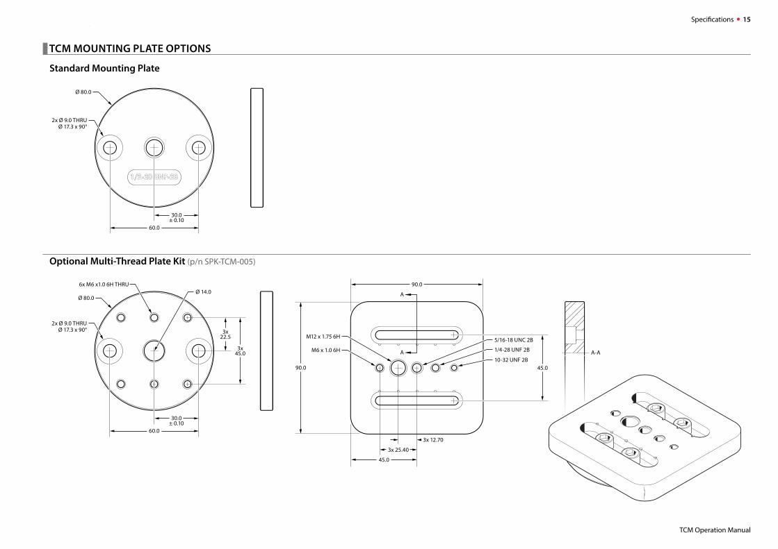
����� TCM MOUNTING PLATE OPTIONS
Standard Mounting Plate
Optional Multi-Thread Plate Kit (p/n SPK-TCM-005)
60.0
2x Ø 9.0 THRUØ 17.3 x 90°
Ø 80.0
30.0± 0.10
60.0
3x22.5
2x Ø 9.0 THRUØ 17.3 x 90°
Ø 80.0Ø 14.0
6x M6 x1.0 6H THRU
30.0± 0.10
3x45.0
90.0
90.0
10-32 UNF 2B
M6 x 1.0 6H
A
A-AA
45.0
M12 x 1.75 6H
1/4-28 UNF 2B
5/16-18 UNC 2B
3x 12.70
3x 25.40
45.0
Support 16
TCM Operation Manual
Support
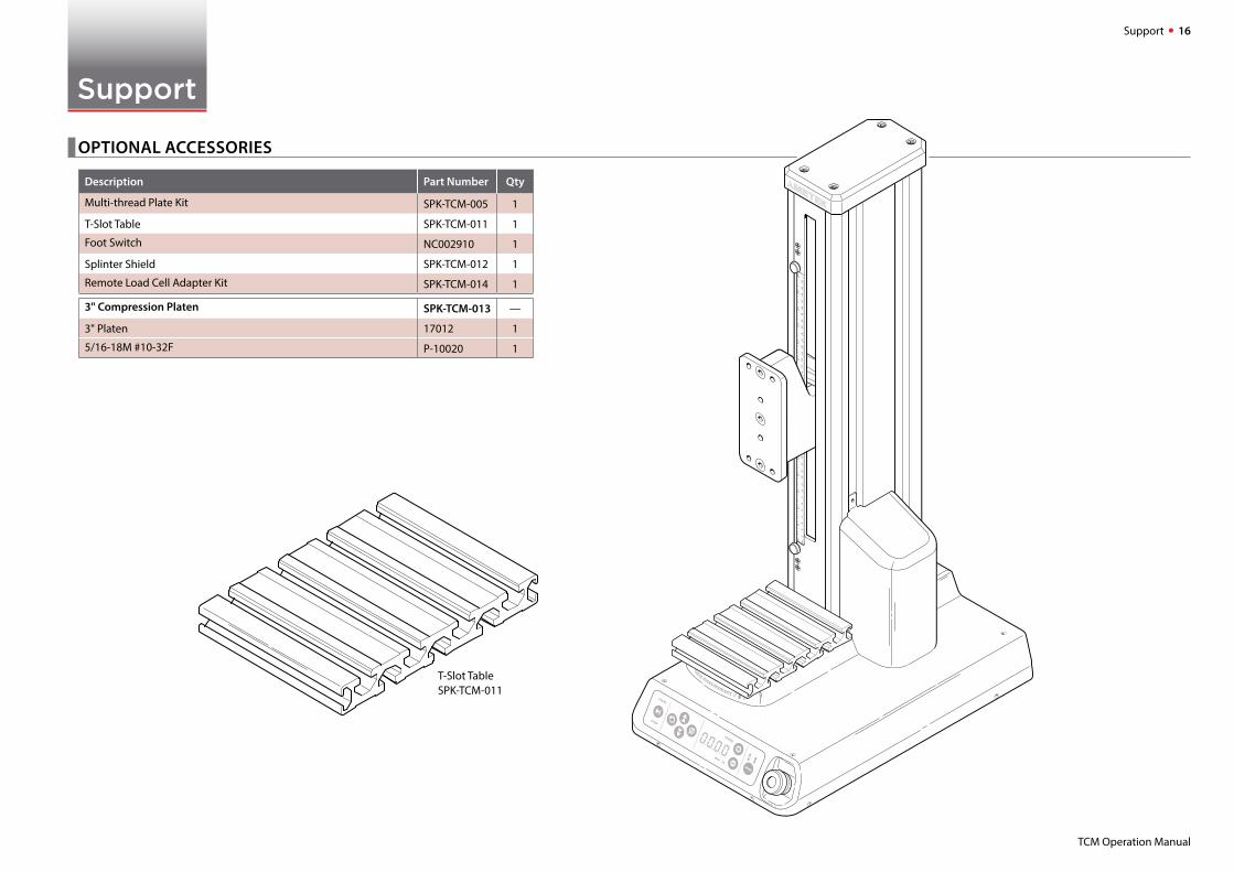
����� OPTIONAL ACCESSORIES
Description Part Number Qty
Multi-thread Plate Kit SPK-TCM-005 1
T-Slot Table SPK-TCM-011 1
Foot Switch NC002910 1
Splinter Shield SPK-TCM-012 1
Remote Load Cell Adapter Kit SPK-TCM-014 1
3" Compression Platen SPK-TCM-013 —
3" Platen 17012 1
5/16-18M #10-32F P-10020 1
MODE
SPEED
STOP
START
T-Slot TableSPK-TCM-011
Support 17
TCM Operation Manual
����� CONTACT US
United KingdomTel +44 (0)1243 833 370
FranceTel +33 (0)1 30 68 89 40
general.lloyd-instruments @ametek.com
GermanyTel +49 (0)2159 9136 510
DenmarkTel +45 4816 8000
USAFlorida
Tel +1 (800) 527 9999
IndiaTel +91 22 2836 4750
ChinaShanghai
Tel +86 21 5868 5111
Beijing
Tel +86 10 8526 2111-19
SingaporeTel +65 6484 2388
����� RETURNING PRODUCT TO AMETEK
Please contact your sales representative to complete a Return Material Authorization (RMA) form and/or receive an RMA number.
Return/shipping instructions will be provided with the RMA number.
����� WARRANTY
This instrument is warranted against defects in workmanship, material and design for two (2) years from date of delivery to the extent that AMETEK will, at its
sole option, repair or replace the instrument or any part thereof which is defective, provided, however, that this warranty shall not apply to instruments subject-
ed to tampering or, abuse, or exposed to highly corrosive conditions.
THIS WARRANTY IS IN LIEU OF ALL OTHER WARRANTIES WHETHER EXPRESS OR IMPLIED AND AMETEK HEREBY DISCLAIMS ALL OTHER WARRANTIES, INCLUDING,
WITHOUT LIMITATION, ANY WARRANTY OF FITNESS FOR A PARTICULAR PURPOSE OR MERCHANTABILITY. AMETEK SHALL NOT BE LIABLE FOR ANY INCIDENTAL
OR CONSEQUENTIAL DAMAGES, INCLUDING, BUT NOT LIMITED TO, ANY ANTICIPATED OR LOST PROFITS.
This warranty is voidable if the purchaser fails to follow any and all instructions, warnings or cautions in the instrument’s Operation Manual.
If a manufacturing defect is found, AMETEK will replace or repair the instrument or replace any defective part thereof without charge; however, AMETEK’s obli-
gation hereunder does not include the cost of transportation, which must be borne by the customer. AMETEK assumes no responsibility for damage in transit,
and any claims for such damage should be presented to the carrier by the purchaser.

6576. B 1905
© 2019 AMETEK Incorporated