Motor starters and “Special Purpose Ratings“ for the ... · Motor starters and “Special...
20
Motor starters and “Special Purpose Ratings“ for the North American market Technical Paper Dipl.-Ing. Wolfgang Esser Third, supplemented edition, 2012 General Purpose Ratings for USA and Canada www.eaton.eu
Transcript of Motor starters and “Special Purpose Ratings“ for the ... · Motor starters and “Special...

Motor starters and
“Special Purpose Ratings“
for the North American market
Technical Paper
Dipl.-Ing. Wolfgang Esser Third, supplemented edition, 2012
General Purpose Ratings for USA and Canada www.eaton.eu
2
Motor starters and “Special Purpose Ratings“
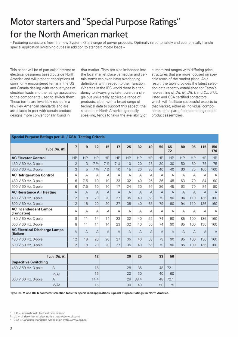
for the North American market– Featuring contactors from the new System xStart range of power products. Optimally rated to safely and economically handle special application switching duties in addition to standard motor loads –
Special Purpose Ratings per UL / CSA- Testing Criteria
Type DIL M..7 9 12 15 17 25 32 40 50 65
7280 95 115 150
170
AC Elevator Control HP HP HP HP HP HP HP HP HP HP HP HP HP HP
480 V 60 Hz, 3-pole 2 3 7 m 7 m 7 m 10 20 25 30 30 50 60 75 75
600 V 60 Hz, 3-pole 3 5 7 m 7 m 10 15 20 30 40 40 60 75 100 100
AC Refrigeration Control A A A A A A A A A A A A A A
480 V 60 Hz, 3-pole 6 7.5 10 10 23 32 40 26 36 45 63 70 84 90
600 V 60 Hz, 3-pole 6 7.5 10 10 17 24 30 26 36 45 63 70 84 90
AC Resistance Air Heating A A A A A A A A A A A A A A
480 V 60 Hz, 3-pole 12 18 20 20 27 35 40 63 79 90 94 110 136 160
600 V 60 Hz, 3-pole 12 18 20 20 27 35 40 63 79 90 94 110 136 160
AC Incandescent Lamps (Tungsten)
A A A A A A A A A A A A A A
480 V 60 Hz, 3-pole 8 11 14 14 23 32 40 55 74 90 85 100 136 160
600 V 60 Hz, 3-pole 8 11 14 14 23 32 40 55 74 90 85 100 136 160
AC Electrical Discharge Lamps (Ballast)
A A A A A A A A A A A A A A
480 V 60 Hz, 3-pole 12 18 20 20 27 35 40 63 79 90 85 100 136 160
600 V 60 Hz, 3-pole 12 18 20 20 27 35 40 63 79 90 85 100 136 160
Type DIL K.. 12 20 25 33 50
Capacitive Switching
480 V 60 Hz, 3-pole A 18 28 36 48 72.1
kVAr 15 20 30 40 60
600 V 60 Hz, 3-pole A 14.4 28 38.4 48 72.1
kVAr 15 30 40 50 75
Type DIL M and DIL K contactor selection table for specialized applications (Special Purpose Ratings) in North America.
1 IEC = International Electrical Commission2 UL = Underwriter‘s Laboratories (http://www.ul.com)3 CSA = Canadian Standards Association (http://www.csa.ca)
This paper will be of particular interest to electrical designers based outside North America and will present descriptions of commonly encountered terms in the US and Canada dealing with various types of electrical loads and the ratings associated to the components used to switch them. These terms are invariably rooted in a few key American standards and are associated in part with certain product designs more conventionally found in
that market. They are also imbedded into the local market place vernacular and cer-tain terms can even have overlapping definitions with respect to their function. Whereas in the IEC world there is a ten-dency to always gravitate towards a sin-gle but universally applicable range of products, albeit with a broad range of technical data to support this aspect, the situation in North America, generally speaking, tends to favor the availability of
customized ranges with differing price structures that are more focused on spe-cific areas of the market place. As a result, the table provides the latest selec-tion data recently established for Eaton’s newest line of DIL M, DIL L and DIL K UL listed and CSA certified contactors, which will facilitate successful exports to that market, either as individual compo-nents, or as part of complete enginereed product assemblies.

3
Photo 1: Presentation of various North American designations associated to load switching requirements for contactors (top), followed by available pro-
duct solutions to accommodate these (middle) and lastly, a sampling of the varied loads addressed by these contactors (bottom). This technical
document deals mainly with the appropriate selection data established for these products to address these differing applications.
General Use Continuous
Current
ResistanceLoads
Lightingloads Capacitors Transformers Elevator
Ratings
Coils(Pilot Duty)
= Categories per NEMA ICS 2, Table 2-4-17
= Load Types per UL 508, Table 62.4
General Purpose Ratings
Industry Standard HP rated Motors
App
licat
ions
Air Conditioning
Resistance Heating
HVAC
Miscellaneous i.e.
Pool, Spa, Vending,
Agriculture, Food
Processing
Ballast
E. Discharge Lamps
Capacitive
Switching
Elevator
Control
MRefrigeration
Control
Tungsten
Incandescent Lamps
Non-Motor Application Motor Application
Sw
itchi
ng
devi
ceLo
ad T
ypes
Transition Flow between
Definite Purpose- and Special Purpose-Applications
DefinitePurpose Contactor
Special Contactor
Standard Contactor
Special Purpose Contactor
100 %
0%
100 %
0%
General Purpose Ratings
In view of the fact that this paper deals mainly with special applications (Special Purpose Ratings or Definite Purpose Rat-ings), it is perhaps advisable to first review some of what is covered under “general“ applications. Or one could say, let’s have a look at “General Purpose Ratings“ (general applications) or “Gen-eral Purpose-Contactors“. Diagram 1 shows, however, that the term “General Purpose Ratings“, and the wording “General Use“, also tend to more readily associate with a grouping of specialized applications. In actual fact, “General Use“ is really the only term for which the qualifier “general“ seems applicable. And it can’t be even considered to be a common application for contactors. The term “General Use“ actually refers to a current rating (Continous Current), which corresponds to the utilization category AC-1 current (thermal current) from the
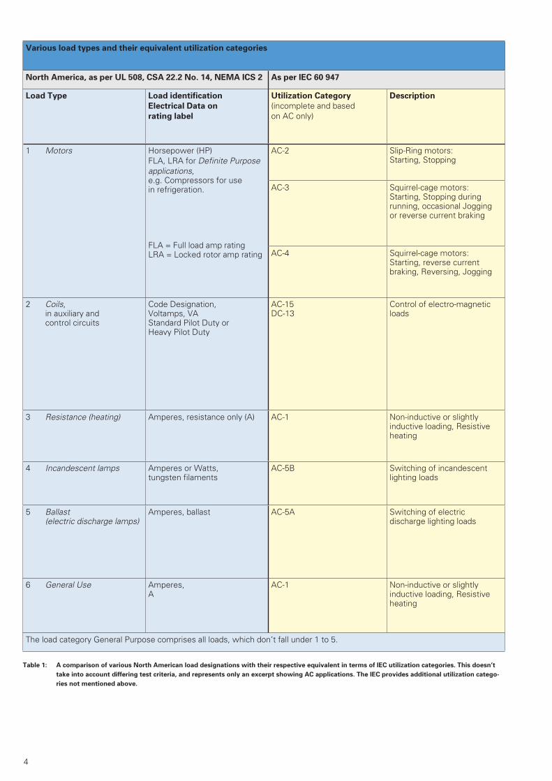
IEC world. Diagram 1 refers to additional and specialized applications and selection criteria, which are referenced as General Purpose ratings in NEMA ICS 2, Table 2-4-17 [13] or as various load types sub-ject to differing test criteria in UL 508 [4], e.g. Table 62.4 of that standard. This data can sometimes also appear on the rating labels of contactors. With respect to “Special Purpose Ratings“, which are described later, the data used for selec-tion allow for customized sizing of con-tactors based on the specific application. Table 1 compares load types for contac-tors in North America with the corre-sponding Utilization Categories per IEC. The comparison refers primarily to the type of load, without touching upon the underlying and divergent test criteria which generate ratings for each respec-tive market. The load types “Coils / Pilot Duty“ needed to be somewhat further separated as a non-motor application cat-egory, since they are more closely asso-
ciated to control circuit loading, whereas the remaining terms specifically deal with elements of the power circuit.
A Basic Function: Switching Motors
The majority of contactors in North Amer-ica are also used mainly for the purpose of switching motors. A term encountered frequently to describe this application would be “Across-the-Line-Motor-Start-ing“, which generally refers to a contac-tor combined with overload protection, possibly including also an overcurrent protective device. When energized, this assembly would permit full line voltage to appear at the motor terminals, as opposed to using the alternative method of reduced voltage as a means of starting the motor. Contactors, such as Eaton Types DIL M [1, 2] rated for World mar-kets, have broad appeal as the ideal solu-tion for these applications. (Diagram 1 +
2). Motor switching is, of course, a major
4
Various load types and their equivalent utilization categories
North America, as per UL 508, CSA 22.2 No. 14, NEMA ICS 2 As per IEC 60 947
Load Type Load identification
Electrical Data on
rating label
Utilization Category
(incomplete and based on AC only)
Description
1 Motors Horsepower (HP) FLA, LRA for Definite Purpose applications, e.g. Compressors for use in refrigeration.
FLA = Full load amp ratingLRA = Locked rotor amp rating
AC-2 Slip-Ring motors: Starting, Stopping
AC-3 Squirrel-cage motors: Starting, Stopping during running, occasional Joggingor reverse current braking
AC-4 Squirrel-cage motors:Starting, reverse current braking, Reversing, Jogging
2 Coils, in auxiliary and control circuits
Code Designation, Voltamps, VAStandard Pilot Duty or Heavy Pilot Duty
AC-15 DC-13
Control of electro-magnetic loads
3 Resistance (heating) Amperes, resistance only (A) AC-1 Non-inductive or slightly inductive loading, Resistive heating
4 Incandescent lamps Amperes or Watts, tungsten filaments
AC-5B Switching of incandescent lighting loads
5 Ballast (electric discharge lamps)
Amperes, ballast AC-5A Switching of electric discharge lighting loads
6 General Use Amperes, A
AC-1 Non-inductive or slightly inductive loading, Resistive heating
The load category General Purpose comprises all loads, which don’t fall under 1 to 5.
Table 1: A comparison of various North American load designations with their respective equivalent in terms of IEC utilization categories. This doesn’t
take into account differing test criteria, and represents only an excerpt showing AC applications. The IEC provides additional utilization catego-
ries not mentioned above.

5
part of the load category array referenced in Table 1. However, it cannot rightfully be grouped under the specialized applica-tions addressed by North American ter-minology such as “General Purpose“, “Special Purpose“ or “Definite Purpose“ since it is a domain largely covered by standard motor contactors with assigned HP values on their rating labels. Generally speaking, one thinks less in North America of applying individual con-tactors for any given application. Rather, one tends to encounter more complete solutions involving assemblies, such as motor starters. The term motor starter infers more complexity, and in its most complete form, such an assembly would incorporate at least 4 essential elements of a motor branch circuit: • Main Disconnect• Overcurrent Protection• Motor controller (switching)• Motor Overload Protectionand would mostly be realized by combin-ing a grouping of components to fulfill these functions.
Photo 2: Universally applicable World Market rated contactors for the xStart Product Range. The
motor starters rated up to 150A are ideally suited for normal industrial motor switching
but the contactors themselves can be applied just as well in North America for “Special
Purpose applications“.
Photo 3: For larger size contactors Eaton has now for years been employing vacuum technology [12] rather than using air as a medium for switching
contacts, thus enabling higher component life and reducing overall dimensions. Most of them are applied in motor starter combinations.
6
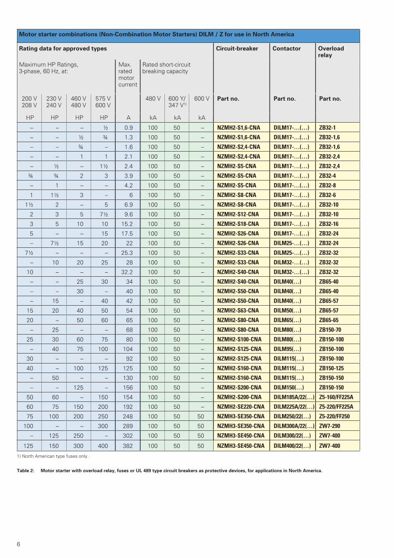
Table 2: Motor starter with overload relay, fuses or UL 489 type circuit breakers as protective devices, for applications in North America.
Motor starter combinations (Non-Combination Motor Starters) DILM / Z for use in North America
Rating data for approved types Circuit-breaker Contactor Overload relay
Maximum HP Ratings, 3-phase, 60 Hz, at:
Max. rated motor current
Rated short-circuit breaking capacity
200 V 208 V
230 V 240 V
460 V 480 V
575 V 600 V
480 V 600 Y/347 V1)
600 V Part no. Part no. Part no.
HP HP HP HP A kA kA kA
– – – ½ 0.9 100 50 – NZMH2-S1,6-CNA DILM17-…(…) ZB32-1
– – ½ ¾ 1.3 100 50 – NZMH2-S1,6-CNA DILM17-…(…) ZB32-1,6
– – ¾ – 1.6 100 50 – NZMH2-S2,4-CNA DILM17-…(…) ZB32-1,6
– – 1 1 2.1 100 50 – NZMH2-S2,4-CNA DILM17-…(…) ZB32-2,4
– ½ – 1½ 2.4 100 50 – NZMH2-S5-CNA DILM17-…(…) ZB32-2,4
¾ ¾ 2 3 3.9 100 50 – NZMH2-S5-CNA DILM17-…(…) ZB32-4
– 1 – – 4.2 100 50 – NZMH2-S5-CNA DILM17-…(…) ZB32-8
1 1½ 3 – 6 100 50 – NZMH2-S8-CNA DILM17-…(…) ZB32-6
1½ 2 – 5 6.9 100 50 – NZMH2-S8-CNA DILM17-…(…) ZB32-10
2 3 5 7½ 9.6 100 50 – NZMH2-S12-CNA DILM17-…(…) ZB32-10
3 5 10 10 15.2 100 50 – NZMH2-S18-CNA DILM17-…(…) ZB32-16
5 – – 15 17.5 100 50 – NZMH2-S26-CNA DILM17-…(…) ZB32-24
– 7½ 15 20 22 100 50 – NZMH2-S26-CNA DILM25-…(…) ZB32-24
7½ – – – 25.3 100 50 – NZMH2-S33-CNA DILM25-…(…) ZB32-32
– 10 20 25 28 100 50 – NZMH2-S33-CNA DILM32-…(…) ZB32-32
10 – – – 32.2 100 50 – NZMH2-S40-CNA DILM32-…(…) ZB32-32
– – 25 30 34 100 50 – NZMH2-S40-CNA DILM40(…) ZB65-40
– – 30 – 40 100 50 – NZMH2-S50-CNA DILM40(…) ZB65-40
– 15 – 40 42 100 50 – NZMH2-S50-CNA DILM40(…) ZB65-57
15 20 40 50 54 100 50 – NZMH2-S63-CNA DILM50(…) ZB65-57
20 – 50 60 65 100 50 – NZMH2-S80-CNA DILM65(…) ZB65-65
– 25 – – 68 100 50 – NZMH2-S80-CNA DILM80(…) ZB150-70
25 30 60 75 80 100 50 – NZMH2-S100-CNA DILM80(…) ZB150-100
– 40 75 100 104 100 50 – NZMH2-S125-CNA DILM95(…) ZB150-100
30 – – – 92 100 50 – NZMH2-S125-CNA DILM115(…) ZB150-100
40 – 100 125 125 100 50 – NZMH2-S160-CNA DILM115(…) ZB150-125
– 50 – – 130 100 50 – NZMH2-S160-CNA DILM115(…) ZB150-150
– – 125 – 156 100 50 – NZMH2-S200-CNA DILM150(…) ZB150-150
50 60 – 150 154 100 50 – NZMH2-S200-CNA DILM185A/22(…) Z5-160/FF225A
60 75 150 200 192 100 50 – NZMH2-SE220-CNA DILM225A/22(…) Z5-220/FF225A
75 100 200 250 248 100 50 50 NZMH3-SE350-CNA DILM250/22(…) Z5-220/FF250
100 – – 300 289 100 50 50 NZMH3-SE350-CNA DILM300A/22(…) ZW7-290
– 125 250 – 302 100 50 50 NZMH3-SE450-CNA DILM300/22(…) ZW7-400
125 150 300 400 382 100 50 50 NZMH3-SE450-CNA DILM400/22(…) ZW7-400
1) North American type fuses only.

7
Photo 4: A PKZM0 motor protective starter grouping is linked on its supply side via a 3 phase bus connector bus. The motor protectors are fed using a
common incoming terminal block BK25...-E , which features larger, distribution size electrical clearances to fulfill the requirements of a “Type E
construction“.
Photo 5: Examples of UL 508 Type F Combination Starters, which consist of UL 508 manual self-protected Type E Combination controllers combined with
standard magnetic contactors.
UL 508 “Type E“
“Type E“-Devices fulfill all 4functions (Main Disconnect, Short Circuit, Overload, Controller).
The Back-up protective switch can be eliminated.
Back-up protective switch
UL 508 “Type F“
“Type F“-Starters consist of a Manual “Type E“-Starter and a magnetic contactor.
The Back-up protective switch can be eliminated.
Back-up protective switch
1 = (Manual) “Type E“-Starter2 = Magnetic contactor
UL 508 Type F Combination Motor Controllers, can be applied without a contactor as UL 508 Manual Type E Self-Protected Combination Motor Controller
Maximum Motor HP Rating3 Phase, 60Hz
Trip settings Interrupting Capacity = Short Circuit Current Rating SCCR
Components
200 V208 V
230 V240 V
460V480 V
575 V600 V
Adjustable thermal
Instantaneous Trip, Fixed
240 V 480Y/277 V2)
600Y/347V2)
Motor Protector
Supply Terminal Contactor
[HP] [HP] [HP] [HP] [A] [A] [kA] [kA] [kA] Part no. Part no. Part no.1) 0.1 - 0.16 2.2 50 50 50 PKZM0-0,16 BK25/3-PKZ0-E DILEM
0.16 - 0.25 3.4 50 50 50 PKZM0-0,25 BK25/3-PKZ0-E DILEM
0.25 - 0.4 5.6 50 50 50 PKZM0-0,4 BK25/3-PKZ0-E DILEM
0.4 - 0.63 8.8 50 50 50 PKZM0-0,63 BK25/3-PKZ0-E DILEM
0.63 - 1 14 50 50 50 PKZM0-1 BK25/3-PKZ0-E DILEM
¾ ¾ 1 - 1.6 22 50 50 50 PKZM0-1,6 BK25/3-PKZ0-E DILEM
½ ½ 1 1 ½ 1.6 - 2.5 35 50 50 50 PKZM0-2,5 BK25/3-PKZ0-E DILEM
¾ ¾ 2 3 2.5 - 4 56 50 50 50 PKZM0-4 BK25/3-PKZ0-E DILEM
1 ½ 1 ½ 3 5 4 - 6.3 88 50 50 50 PKZM0-6,3 BK25/3-PKZ0-E DILEM
3 3 7 ½ 10 6.3 - 11 140 50 50 50 PKZM0-10 BK25/3-PKZ0-E DILEM
1) 0.1 - 0.16 2.2 65 65 - PKZM0-0,16 BK25/3-PKZ0-E DILM7
0.16 - 0.25 3.4 65 65 - PKZM0-0,25 BK25/3-PKZ0-E DILM7
0.25 - 0.4 5.6 65 65 - PKZM0-0,4 BK25/3-PKZ0-E DILM7
0.4 - 0.63 8.8 65 65 - PKZM0-0,63 BK25/3-PKZ0-E DILM7
0.63 - 1 14 65 65 - PKZM0-1 BK25/3-PKZ0-E DILM7
¾ ¾ 1 - 1.6 22 65 65 - PKZM0-1,6 BK25/3-PKZ0-E DILM7
½ ½ 1 1 ½ 1.6 - 2.5 35 65 65 - PKZM0-2,5 BK25/3-PKZ0-E DILM7
¾ ¾ 2 3 2.5 - 4 56 65 65 - PKZM0-4 BK25/3-PKZ0-E DILM7
1 ½ 1 ½ 3 5 4 - 6.3 88 65 65 - PKZM0-6,3 BK25/3-PKZ0-E DILM7
3 3 7 ½ 10 6.3 -11 140 65 65 - PKZM0-10 BK25/3-PKZ0-E DILM12
3 3 7 ½ - 9 - 12 168 50 50 - PKZM0-12 BK25/3-PKZ0-E DILM15
3 - - - 10 - 16 224 18 18 - PKZM0-16 BK25/3-PKZ0-E DILM17
5 - - - 16 - 20 280 18 18 - PKZM0-20 BK25/3-PKZ0-E DILM25
- 7 ½ 15 - 20 - 25 350 18 18 - PKZM0-25 BK25/3-PKZ0-E DILM25
7 ½ 10 20 - 24 - 32 448 18 18 - PKZM0-32 BK25/3-PKZ0-E DILM32
3 5 10 15 10 - 16 224 65 65 50 PKZM4-16 BK50/3-PKZ4-E DILM32
5 7 ½ 15 20 16 - 27 350 65 65 50 PKZM4-25 BK50/3-PKZ4-E DILM32
7 ½ 10 25 30 24 - 34 448 65 65 50 PKZM4-32 BK50/3-PKZ4-E DILM32
10 - 30 30 32 - 40 560 65 65 50 PKZM4-40 BK50/3-PKZ4-E DILM40
- 15 30 - 40 - 52 700 65 65 - PKZM4-50 BK50/3-PKZ4-E DILM50
- - 40 - 50 - 56 812 65 65 - PKZM4-58 BK50/3-PKZ4-E DILM65
- - 40 - 52 - 58 882 65 65 - PKZM4-63 BK50/3-PKZ4-E DILM651) In this range, select devices per motor full load current. Refer to NEC Table 430-250. 2) Solidly grounded power distribution system. Stand: March 2010
Table 3a: Electromechanical motor-protective circuit-breaker PKZM in UL 508 Type F Combination Starters

8
As it is the practice in other countries which have adopted IEC standards, there is also a tendency in North America to differentiate between motor starters which feature fuses as the primary over-current protective device (Table 2a + 2b) and those which are considered fuseless, (Table 3a + b, Photos 3 +4), and have either motor protectors or molded case circuit breakers as their core overcurrent protective element. The latter combina-tions are rapidly gaining in popularity because of the many additional features and benefits they can offer in modern installations. The tables reflect motor starter combina-tions featuring Eaton’s conventional line
of DIL M motor switching contactors. These standard contactors are part of Eaton’s comprehensive new line of “Sys-tems xStart“ industrial control motor starter components. (Diagram 5). A brand new feature of this innovative new line is the toolless connector system which provides the mechanical and elec-trical link between the motor protector and the magnetic contactor. (Diagram 6). It’s also designed and rated to cover the highest volume range of motors. These new, and labor saving connector pieces are UL listed and CSA certified and can also be used in combination with Eaton motor starter assemblies mounted on customized space saving bus bar adapt-
ers. Furthermore, they feature UL/CSA high fault short circuit ratings, making them particularly desirable in North American industrial control panel assem-blies which now mandate short circuit ratings for compliance with domestic electrical Codes. Refer to Table 3a + b for selection guidance on these motor starter components.
Particular North American requirements on motor starters, as well as component assemblies considered unconventional in the IEC world, are covered at length in a separate Eaton technical document [3] available for reference. The special con-siderations described therein are due
4 SCCR = Short Circuit Current Rating5 HP = Horsepower, 1 HP =̃ 1 PS
NEMA-Sizes für Contactors per the NEMA ICS 2 standard
3 Phase contactors per NEMA
NEMA-Sizes
Rated current HP Ratings 1)
1-phase 3-phase
120 V 60 Hz(115 V 60 Hz)
240 V 60 Hz(230 V 60 Hz)
208 V 60 Hz(200 V 60 Hz)
240 V 60 Hz(230 V 60 Hz)
480 V 60 Hz(460 V 60 Hz)600 V 60 Hz(575 V 60 Hz)
A HP (PS) HP (PS) HP (PS) HP (PS) HP (PS)
00 9 ½ 1 1 ½ 1 ½ 2
0 18 1 2 3 3 5
1 27 2 3 7 ½ 7 ½ 10
2 45 3 7 ½ 10 15 25
3 90 7 ½ 15 25 30 50
4 135 - - 40 50 100
5 270 - - 75 100 200
6 540 - - 150 200 400
7 810 - - - 300 600
8 1215 - - - 450 900
9 2250 - - - 800 1600
1) HP Ratings for single speed motors, without jogging, reversing and current breaking.
Table 4: North American NEMA-Sizes for contactors. A NEMA-Size has an assigned general purpose current rating along with definite HP values at vari-
ous motor nominal voltage ratings. All values per each NEMA size must be covered by one device in order for it to be assigned that designation.
UL 508 Type E - Self-Protected Combination Motor Controllers
consisting of electronic motor-protective circuit-breaker PKE and contactor DILM, can also be used as “UL 508 Type F Combina-tion Motor Starters”Max. HP-Rating SCCR [kA] Design using switchgear:
200 V, 60 Hz
240 V, 60 Hz
480Y/277 V,60 Hz
600Y/347 V,60 Hz
480Y/277V, 60 Hz
600Y/347V, 60 Hz
Motor-protective circuit-breakerplus BK25/3-…-E
Contactor(manda-tory)
Type
- - 0.5 0.5 14 14 PKE1,2 DIL M17 MSC-..-1,2-M17-SP0.75 0.75 2 - 18 - PKE4 DIL M17 MSC-..-4-M17-SP3 3 7.5 - 18 - PKE12 DIL M17 MSC-..-12-M17-SP5 7.5 15 - 18 - PKE32 DIL M32 MSC-..-32-M32-SP
Table 3b: Electronic motor-protective circuit-breaker PKE in UL 508 Type E Self-Protected Combination Motor Controllers. Caution: In this case when motor-
protective circuit-breakers PKE are used, a contactor is already included in the Type E controller. Here UL 508 type E combinations can be used as
well as UL 508 type F combinations.

9
Range (s)
66
10
Time
1 100
58
65
57
NC
NO
2 T1 4 T2 6 T3
22
31
30
27
23
28
19
33
34
26
29
932 9
65
5
101010
4
17 17
32
1
12
8
16
15
141114
11
9
26
713
28
26
20
21
18
42
3736
38 39
35
40 41
2524
43New
New
Excerpt from the SystemView without PKZM 4. For the complete range, see the current Main Catalogue.Auxiliary and main current connections up to 15 A, either with screw terminals or spring-loaded terminals.
Photo 6: System xStart motor starter breakdown, with particular emphasis on advantageous mounting and wiring aids such as toolless plug-in connec-
tors and bus bar adapters. These components and combinations have been designed as world market products and feature UL and CSA approv-
als for use in North America.
Contactors
1 Contactor up to 15 A 2 Contactor up to 38 A 3 Contactor up to 65 A 4 Contactor up to 170 A 5 Top-mounted auxiliary contact 6 Electronic timer module 7 Motor filter 8 Side-mounted auxiliary contact 9 Side-mounted auxiliary contact 10 Top-mounted auxiliary contact 11 Suppressor circuit 12 PE-module with spring 13 4-pole motor outgoer connector
Overload Relays
14 Overload relay up to 38 A 15 Overload relay up to 65 A 16 For separate mounting 17 Overload relay up to 170 A
Motor-Protective Switches
18 Motor-Protective Switchwith rotary actuation
19 Motor-Protective Switchwith pushbutton actuation
20 Electronic motor-protectivecircuit-breaker
21 Incomer terminal 22 Current limiter module 23 Shunt- and undervoltage releases 24 Trip-indicating auxiliary contact 25 Side-mounted auxiliary contact 26 Front auxiliary contact 27 Early-make auxiliary contact 28 Door-coupling rotary handle
and extension shaft 29 Early-make auxiliary contact 30 Insulated flush mounting enclosure 31 Insulated surface mounting enclosure
with Emergency-Stop pushbutton
Links and starters
32 Electrical link 33 Mechanical link 34 Combination plug-in connector 35 Motorstarter PKZ with
combination plug-in technology 36 Clip plate 37 Motorstarter PKE with
combination plug-in technology 38 Busbar adapter 39 Top-hat rail adapter
SmartWire-DT
40 Flat plug 41 Flat cable 42 Function element, DIL/MSC 43 Function element, PKE
10
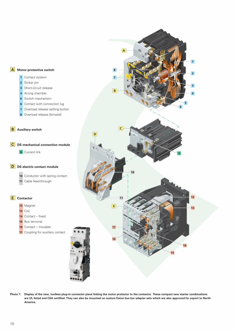
B
C
D
E
A Motor-protective switch
1 Contact system
2 Striker pin
3 Short-circuit release
4 Arcing chamber
5 Switch mechanism
6 Contact with connection lug
7 Overload release setting button
8 Overload release (bimetal)
DS electric contact module
10 Conductor with spring contact
11 Cable feed-through
DS mechanical connection module
9 Current link
Auxiliary switch
Contactor
12 Magnet
13 Coil
14 Contact – fixed
15 Box terminal
16 Contact – movable
17 Coupling for auxiliary contact
Photo 7: Display of the new, toolless plug-in connector piece linking the motor protector to the contactor. These compact new starter combinations
are UL listed and CSA certified. They can also be mounted on custom Eaton bus bar adapter sets which are also approved for export to North
America.
11
largely in part to the peculiar categories under which motor protectors and circuit breakers used in motor starter assem-blies are grouped per the relevant UL 508 [4] and UL 489 [5] product testing stan-dards in the US, and the respective coun-terpart CSA-C22.2 No. 14 [6] and CSA-C22.2 No. 5-02 [7] standards in Canada. The first set of standards mentioned for each respective country deals mostly with devices and assemblies used in the “controller portion of the circuit“ (Indus-trial Control Equipment), whereas the second grouping is considered more stringent in terms of component demands since it applies to devices with primary protective functions in the feeder and branch energy distribution portion of the electrical system (Distribution Equip-
ment). Energy distribution components also feature prominently in the electrical systems for machines and general indus-trial control apparatus, particularly in the supply side as well as on feeder bus sys-tems used throughout the more complex assemblies.
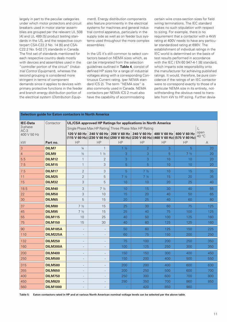
In the US it’s still common to select con-tactors based on NEMA sizes which, as can be interpreted from the selection guidelines outlined in Table 4, consist of defined HP sizes for a range of industrial voltages along with a corresponding Con-tinuous Current rating. (per NEMA stan-dard ICS 2). The term “NEMA size“ is also commonly used in Canada. NEMA contactors per NEMA ICS 2 must also have the capability of accommodating
certain wire cross-section sizes for field wiring terminations. The IEC standard makes no such stipulation with respect to sizing. For example, there is no requirement that a contactor with a 4kW rating at 400V needs to have any particu-lar standardized rating at 690V. The establishment of individual ratings in the IEC world is determined on the basis of test results performed in accordance with the IEC / EN 60 947-4-1 [8] standard, which imparts sole responsibility onto the manufacturer for achieving published ratings. It would, therefore, be pure coin-cidence if the ratings of an IEC contactor were to correspond exactly to those of a particular NEMA size in its entirety, not-withstanding the obvious need to trans-late from kW to HP sizing. Further devia-
Selection guide for Eaton contactors in North America
IEC-Data3-phase AC-3400 V 50 Hz
Contactor UL/CSA approved HP Ratings for applications in North America
Single Phase Max HP Rating Three Phase Max HP Rating Ith open40 °C
120 V 60 Hz (115 V 60 Hz)
240 V 60 Hz (230 V 60 Hz)
208 V 60 Hz (200 V 60 Hz)
240 V 60 Hz (230 V 60 Hz)
480 V 60 Hz (460 V 60 Hz)
600 V 60 Hz (575 V 60 Hz)
kW Part no. HP HP HP HP HP HP A
3 DILM7 ¼ 1 1 ½ 2 3 5 20
4 DILM9 ½ 1 ½ 3 3 5 7 ½ 20
5.5 DILM12 1 2 3 3 10 10 20
7.5 DILM15 1 3 5 5 10 10 20
7.5 DILM17 2 3 5 7 ½ 10 15 35
11 DILM25 2 5 7 ½ 7 ½ 15 20 35
15 DILM32 3 5 10 10 20 25 40
18.5 DILM40 3 7 ½ 10 15 30 40 55
22 DILM50 3 10 15 20 40 50 65
30 DILM65 5 15 20 25 40 60 80
37 DILM80 7 ½ 15 25 30 60 75 125
45 DILM95 7 ½ 15 25 40 75 100 125
55 DILM115 10 25 40 50 100 125 160
75 DILM150 15 30 40 60 125 125 160
90 DILM185A - - 50 60 125 150 225
110 DILM225A - - 60 75 150 200 250
132 DILM250 - - 75 100 200 250 350
160 DILM300A - - 100 125 250 300 350
200 DILM400 - - 150 150 300 400 450
250 DILM500 - - 150 200 400 500 550
315 DILM580 - - 200 200 400 600 630
355 DILM650 - - 200 250 500 600 700
400 DILM750 - - 250 300 600 700 800
450 DILM820 - - 290 350 700 860 850
560 DILM1000 - - - 420 850 980
Table 5: Eaton contactors rated in HP and at various North American nominal voltage levels can be selected per the above table.

12
100
90
80
70
60
50
40
30
20
10
0
0,05 0,1 0,2 0,5
tions would also include voltage and fre-quency ratings, which are different on the North American continent. NEMA Sizes simply reflect an in-country stan-dardization method and a convenient method for component selection, and is neither an indication of any particular quality level, nor is their usage always strictly required. NEMA-contactors are usually also larger in size dimensionally. In the IEC world the selection process for a contactor normally involves the use of a manufacturer’s catalog along with spe-cific knowledge of the rating and type of load to be switched, the corresponding utlization category and the voltage at which the load is operating. In North America the process can be as straight-forward as requesting a distributor to
supply a “NEMA Size 2“ contactor, which could then come from a variety of manufacturers. It would then feature all the typical ratings associated to that size, including standardized HP ratings and corresponding continuous current. In view of the fact that, in any given appli-cation, there is the greater likelihood of having a single set of voltage/current parameters, it is questionable whether the idea of a device providing additional standardized HP pairings at different volt-age levels can be that advantageous in the majority of cases.
From a practical standpoint, companies which export to North America should best select contactors such as those outlined in Table 5, or from motor starter combination tables providing
selections with or without protective devices. Table 5 outlines contactor sizes which would more closely match any given motor rating, thus allowing the choice of a possibly smaller and more economical device for the purpose. Selections per Table 5 can be easily and readily done since all ratings shown are approved and appear on the contactor’s rating label. The large majority of contactors are used in full voltage, across-the-line motor start-ing applications, both in non-reversing and reversing combinations. Electro-mag-netic contactors are still found in a num-ber of applications involving reduced volt-age starting, the most popular of which in North America would include the use of motor starting auto-transformers and special part-winding motors. Open transi-tion star-delta motor starting is not as popular there as it is in Europe, due in part to the relatively lesser amount of electrical networks using the 1/√3 vecto-rial relationship provided with supply con-ductors in 4 wire systems. On the other hand, certain industries such as refrigera-tion do on occasion employ star-delta motors for large hermetic motor com-pressors, and switching duties for those could be shared with up to 4 contactors since these would more than likely fea-ture closed transition starting. Eaton con-tactors are world market devices and thus the same version can be safely applied on all continents. Eaton contac-tors also feature export friendly double voltage coils, which can be reliably ener-gized with control power sources at both 50Hz and 60Hz standard control circuit voltage levels. Contactors are increas-ingly being energized with power sup-plied from electronic control sources. The majority of these cases would involve the use of export neutral DC coils, mostly in 24VDC [9] versions. During the first half of 2006 Eaton will be introducing spe-cially designed coils which will be in fulI compliance with the more stringent volt-age sag immunity requirements (SEMI1 F47 [10]) of the American semi-conduc-tor industry (Diagram 7). Eaton contac-tors can be conveniently selected using either kW or HP ratings depending on the actual motor rating. Machine manufactur-ers exporting to North America will often include IEC motors in their designs, and these will invariably be rated in kW as well as incorporate metric dimensioning features. It’s especially useful in these cases, therefore, to use components such as Eaton contactors with both kW and HP values on their rating labels since many local inspectors will not accept motor controllers which are not rated in HP, as it is a violation of the local electri-cal Codes.
Photo 8: The American Semi-Conductor industry in its SEMI F47 standard requires an increased level
of safeguarding against premature contactor coil drop-out during normal operation. In the
area shaded in green, the main contacts of the contactor are not allowed to open. This re-
quirement can be fully accommodated with specialized magnet systems in Eaton’s System
xStart range of contactors.
Duration of Voltage Sag in Seconds
Perc
en
t o
f C
on
tacto
r N
om
inal
Co
ntr
ol
Cir
uit
Vo
ltag
e
Permissible working range
of contactor coil acc. SEMI F 47
added safety withEaton contactors DIL MF
Undefined Range
Source: www.semi.org
6 SEMI = Semiconductor Equipment and Materials Institute 7 HVAC = Heating Ventilation Air Conditioning
13
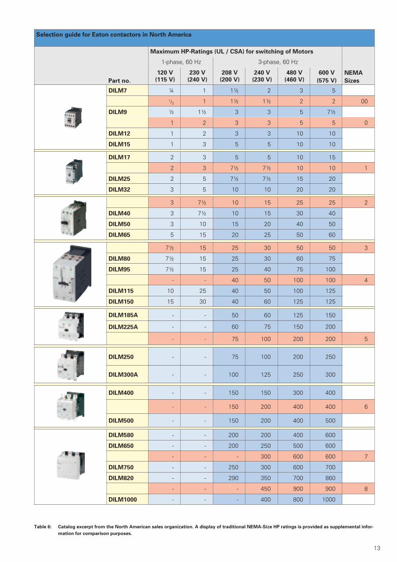
Table 6: Catalog excerpt from the North American sales organization. A display of traditional NEMA-Size HP ratings is provided as supplemental infor-
mation for comparison purposes.
Selection guide for Eaton contactors in North America
Part no.
Maximum HP-Ratings (UL / CSA) for switching of Motors
1-phase, 60 Hz 3-phase, 60 Hz
NEMA
Sizes
120 V
(115 V)
230 V
(240 V)
208 V
(200 V)
240 V
(230 V)
480 V
(460 V)
600 V
(575 V)
DILM7 ¼ 1 1½ 2 3 5
1/3 1 1½ 1½ 2 2 00
DILM9 ½ 1½ 3 3 5 7½
1 2 3 3 5 5 0
DILM12 1 2 3 3 10 10
DILM15 1 3 5 5 10 10
DILM17 2 3 5 5 10 15
2 3 7½ 7½ 10 10 1
DILM25 2 5 7½ 7½ 15 20
DILM32 3 5 10 10 20 20
3 7½ 10 15 25 25 2
DILM40 3 7½ 10 15 30 40
DILM50 3 10 15 20 40 50
DILM65 5 15 20 25 50 60
7½ 15 25 30 50 50 3
DILM80 7½ 15 25 30 60 75
DILM95 7½ 15 25 40 75 100
- - 40 50 100 100 4
DILM115 10 25 40 50 100 125
DILM150 15 30 40 60 125 125
DILM185A - - 50 60 125 150
DILM225A - - 60 75 150 200
- - 75 100 200 200 5
DILM250 - - 75 100 200 250
DILM300A - - 100 125 250 300
DILM400 - - 150 150 300 400
- - 150 200 400 400 6
DILM500 - - 150 200 400 500
DILM580 - - 200 200 400 600
DILM650 - - 200 250 500 600
- - - 300 600 600 7
DILM750 - - 250 300 600 700
DILM820 - - 290 350 700 860
- - - 450 900 900 8
DILM1000 - - - 400 800 1000
14
Whereas Table 5 provides the IEC rat-ings at 400V/50 Hz and the North Ameri-can continuous rated currents as addi-tional information, Table 6 gives an indi-cation of NEMA sizes for orientation purposes to further assist in the selection process. The impact of NEMA sized con-tactors has been somewhat diminished over the years by the steady increase in North America of machines and electrical assemblies imported from overseas. It can be argued that foreign manufacturers of machines and electrical equipment have enjoyed a technological edge in many aspects and this has led to greater acceptance and appreciation on the North American market for the positive design aspects of the smaller IEC style switching and protective components. It is worth noting that most American man-ufacturers of electrical equipment have in the meantime expanded their product lines to include smaller design IEC devices to meet the increased demand, not only in their own domestic backyard but on foreign soil as well. To make prog-ress on the European front it’s also man-datory to secure the CE mark in order to gain legal access to the EU markets. A portion of their product range expansion has come from Eaton’s own design rooms and production facilities. The recently introduced American standard UL 60947 will promote to an even greater degree the march towards har-monization with the IEC 60947 standard, whereby a certain amount of reciprocity to allow American aspects into the IEC normative document will surely also take place.
Special Purpose Contactors
It’s also the case in North America that not all electrical loads consist typically of squirrel cage motors, and that particular requirements based on specific loading duties, including specialized applications, need to be taken into consideration. For this reason there are special testing crite-ria in place to match the power and cur-rent parameters placed upon compo-nents by these specialized applications, e.g. elevator duty and refrigeration con-trol to name a few, and verify the ability of contactors to safely and reliably handle those particular load demands. Additional non-motor type loads include typical industrial lighting (Tungsten, Incandes-cent Lamps) as well as Ballast and Gas Discharge Lamp assemblies, resistive type loading (Air conditioning and Resis-tance Heating, HVAC 2) and the switch-
ing of Capacitors, typically used in individ-ual or group power factor compensation applications.
The scope of “Special Purpose Ratings“ assigned to standard or customized con-tactors for special markets can expand into a variety of applications, including:
• Pumps and compressors• Hoists and cranes• Welding equipment• Power supplies• Food processing• Vending machines• Agricultural applications
(Refer also to the various loads specified in the lower portion of Diagram 1).
Some of these applications are also cov-ered through specialized testing under IEC Utilization Categories, referenced in
Table 1. These involve standardized test set-ups with prescribed synthetic load-ing3, which more or less mimic the actual demands placed on switching devices in those applications. Eaton, however, places a greater emphasis on duplicating actual field conditions to test the suitablil-ity of its devices by performing tests using actual load equipment, often in
concert with various well-known manu-facturers of equipment such as capaci-tors, lighting, gas discharge lamps etc... in order to obtain more practical and rele-vant verification of the true capabilities of its components.
Contactors for Special Purpose Applica-tions could, in theory, require to be spe-cially designed to handle these differing switching demands. Eaton chooses instead to test and assign the large share of special purpose duties to its line of universally applicable motor switching DIL M contactors. There is an exception to that approach and it con-cerns Eaton contactors Type DIL K, which have been specially optimized to reliably switch capacitors in capacitor banks. Eaton is currently in the process on achieving special purpose contactor ratings for 3 phase applications. Whereas General Purpose and Definite Purpose ratings are mentioned and cov-ered in the UL 508 Industrial Control standard, the term Special Purpose is one which has been used mostly by manufacturers and users of electrical equipment to address these specialized applications. Eaton considers the major-ity of these special purpose applications to be well within the grasp of its stan-dard motor switching line of DIL M con-
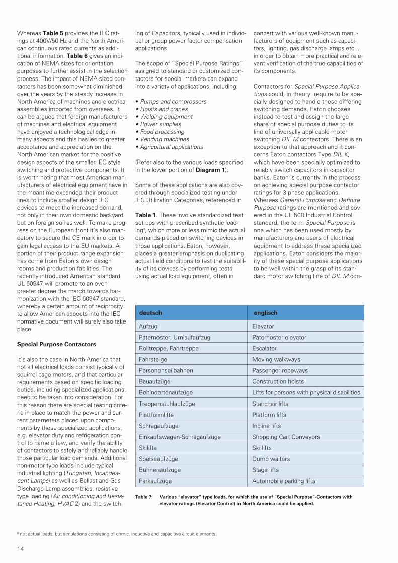
deutsch englisch
Aufzug Elevator
Paternoster, Umlaufaufzug Paternoster elevator
Rolltreppe, Fahrtreppe Escalator
Fahrsteige Moving walkways
Personenseilbahnen Passenger ropeways
Bauaufzüge Construction hoists
Behindertenaufzüge Lifts for persons with physical disabilities
Treppenstuhlaufzüge Stairchair lifts
Plattformlifte Platform lifts
Schrägaufzüge Incline lifts
Einkaufswagen-Schrägaufzüge Shopping Cart Conveyors
Skilifte Ski lifts
Speiseaufzüge Dumb waiters
Bühnenaufzüge Stage lifts
Parkaufzüge Automobile parking lifts
Table 7: Various “elevator“ type loads, for which the use of “Special Purpose“-Contactors with
elevator ratings (Elevator Control) in North America could be applied.
8 not actual loads, but simulations consisting of ohmic, inductive and capacitive circuit elements.
15
tactors, and conducts tests accordingly to generate the necessary data associ-ated to these applications in order to verify their suitability.
Definite Purpose Contactors
Besides contactors optimized for North American Special Purpose ratings, which Eaton covers with its line of conventional and high volume industrial contactors Type DILM, the North American market features a particular variety referred to as “Definite Purpose“ contactors. Definite-Purpose contactors (Contactors espe-cially designed to accommodate specific applications) consist mostly of special-ized, and cost optimized, constructions generally considered to be a notch below the design level of con-ventional industrial switching contactors (e.g. they generally feature reduced lifes-pan, greater amounts of exposed parts with consequent reduced shock hazard protection, and are usually equipped with less sophisticated connection means).
These controllers often display uncon-ventional designs or they consist mostly of single and double pole constructions. Definite-Purpose contactors will certainly cross paths to various degrees with con-tactors used in the range of applications previously described as Special Purpose. They are especially popular in HVAC applications and a host of other applica-tions, including low cost serial production equipment such as vending machines and the like. Domestically available prod-ucts are usually the components of choice preferred by North American users for these applications. The Definite Purpose contactor market is not one in which Eaton actively partici-pates, with the possible exception of specific customer related requirements which are normally met with the stan-dard industrial control line of contactors. The next parapraphs will highlight in greater detail significant aspects of con-tactor selection criteria with respect to various loading duties (as referenced in the lower portion of Diagram 1).
Elevator control
One could get the impression that con-tactors rated for elevator duty represent only a small segment of the market. However, as Table 7 infers, that doesn’t necessarily seem to be the case. Although it may not encompass all variations, the table still reflects a good number of constructively related derivations of this particular transporta-tion mode for which the same switch-ing duty requirements could also be deemed applicable. At the very least, it’s a market segment which is expanding in significance. In Europe, for example, where space in nar-row and crowded cities is always at a premium, the need arose years ago to provide car parking elevator facilities in certain city venues. That same trend can be seen spreading across North America. The requirement to provide additional transport means in varying sizes and con-figurations is evidently also becoming a necessity on that continent.
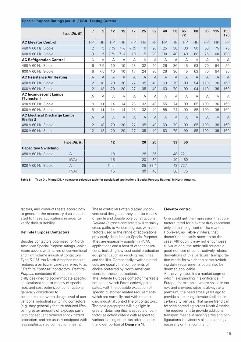
Special Purpose Ratings per UL / CSA- Testing Criteria
Type DIL M..7 9 12 15 17 25 32 40 50 65
7280 95 115 150
170
AC Elevator Control HP HP HP HP HP HP HP HP HP HP HP HP HP HP
480 V 60 Hz, 3-pole 2 3 7 ½ 7 ½ 7 ½ 10 20 25 30 30 50 60 75 75
600 V 60 Hz, 3-pole 3 5 7 ½ 7 ½ 10 15 20 30 40 40 60 75 100 100
AC Refrigeration Control A A A A A A A A A A A A A A
480 V 60 Hz, 3-pole 6 7.5 10 10 23 32 40 26 36 45 63 70 84 90
600 V 60 Hz, 3-pole 6 7.5 10 10 17 24 30 26 36 45 63 70 84 90
AC Resistance Air Heating A A A A A A A A A A A A A A
480 V 60 Hz, 3-pole 12 18 20 20 27 35 40 63 79 90 94 110 136 160
600 V 60 Hz, 3-pole 12 18 20 20 27 35 40 63 79 90 94 110 136 160
AC Incandescent Lamps (Tungsten)
A A A A A A A A A A A A A A
480 V 60 Hz, 3-pole 8 11 14 14 23 32 40 55 74 90 85 100 136 160
600 V 60 Hz, 3-pole 8 11 14 14 23 32 40 55 74 90 85 100 136 160
AC Electrical Discharge Lamps (Ballast)
A A A A A A A A A A A A A A
480 V 60 Hz, 3-pole 12 18 20 20 27 35 40 63 79 90 85 100 136 160
600 V 60 Hz, 3-pole 12 18 20 20 27 35 40 63 79 90 85 100 136 160
Type DIL K.. 12 20 25 33 50
Capacitive Switching
480 V 60 Hz, 3-pole A 18 28 36 48 72.1
kVAr 15 20 30 40 60
600 V 60 Hz, 3-pole A 14.4 28 38.4 48 72.1
kVAr 15 30 40 50 75
Table 8: Type DIL M und DIL K contactor selection table for specialized applications (Special Purpose Ratings) in North America.

16
The endurance tests to verify elevator duty controller ratings, which are per-formed at twice the motor full load cur-rent, rank amongst the most stringent in special purpose application verification testing. Contactors with elevator duty rat-ings are used primarily for the main motors which govern motion. Certain ele-vator manufacturers take it a step further and include them in additional safety related aspects such as braking or, for example, as part of the mechanism to operate doors, which can be considered just as vital when it comes to the overall safety and reliability of the entire elevator assembly. The selection data for Eaton contactors rated for elevator duty can be found in Table 8.
Resistive loading (Air conditioning und Resistance Heating, HVAC)
Switching resistive loads, i.e. loads which are primarily resistive or perhaps feature only a slightly inductive or capacitive component (IEC Utiliazation category AC-1) can be characterized as amongst
the easiest for a contactor to handle, sim-ply because switching demands are per-formed at, or nearly at, the contactor’s continuous current rating. The need to make, and possibly break, a multiple of the load current, such as is the case with motors, lighting, capacitors and trans-formers, does not apply. The lighter duty encountered in resistive switching appli-cations will minimize contact burning on the contactor’s main switching contact elements. In Canada, the endurance requirements for resistive heating loads in accordance with local standards is 2.5 times greater than corresponding require-ments per US standards, and the test is made even more demanding since it is run at the higher nominal voltage rating of 600V, which is the predominant nomi-nal voltage rating in Canada.
AC-1 current values of Eaton DIL M con-tactors are higher than their correspond-ing motor switching ratings. That means that smaller and more economical devices can be used to adequately han-dle resistive loads of the same ampacity
as more inductive motor loading levels. AC-1 switching conditions relate fre-quently to loads such as resistive heating ovens and electric space heaters. That’s been the basis, therefore, for the com-monly encountered term “Heating Con-tactors“, a reference which has been popularly associated in the market place to devices used in those applications. Resistive loads such as these will quite often be single phase only. The DILM-XP1 paralleling bridge accessory will then permit all 3 poles to be switched in paral-lel. (Photo 8). That allows the permissi-ble thermal current rating of a 3 pole con-tactor to increase by a factor of 2.5, thus enabling the selection of a smaller device to handle the load. The use of a load pro-tective overload relay is usually not required in resistive heating applications since it is not possible to generate over-loading in a heater. Suitable protection of conductors and cables is, however, nec-essary, and the ampacity levels of con-ductors used in continuous duty applica-tions is generally not allowed to exceed 80% of maximum loading. The conven-tional solution in North America would be to provide listed molded case circuit breakers as protective devices, equipped with fixed overload and overcurrent set-tings.
AC-1-Contactors will also often be used in conjunction with power electronic switching devices for galvanic separation of loads within a circuit. In those applica-tions the load current is switched ON and OFF electronically and the contactor is subject solely to the continuous current. Proper electrical interlocking circuitry should be introduced to insure load free switching of the contactor. In the event that the contactors would also be called upon to occasionally accomplish Emer-gency-OFF switching duties, it would be necessary during the contactor selection process to factor in a likely number of required Emergency-OFF operations, and to consider how high of a current would need to be switched during those opera-tions. Because the heat losses of mechanical contacts are so much less than corresponding electronic power switchin components, AC1-Contactors are also often used as by-pass contactors for soft starters. They can also be deemed in that capacity to be providing a certain protective or “insurance“ func-tion, in that during the time the current is flowing through the bypass contactors, the more vulnerable power electronic devices are not subject to potentially damaging overload and short-circuit cur-rent levels. The selection guidelines for Eaton contactors in these applications is provided in Table 8.
Photo 9: The paralleling bridge allows the AC-1 “General Purpose“ 3 phase current rating of the
contactor to be increased by a factor 2.5 times its value. This accessory is especially useful
when switching single phase resistive loads (such as heaters). It permits the use of smaller,
and more economical, contactors to handle the load.
17
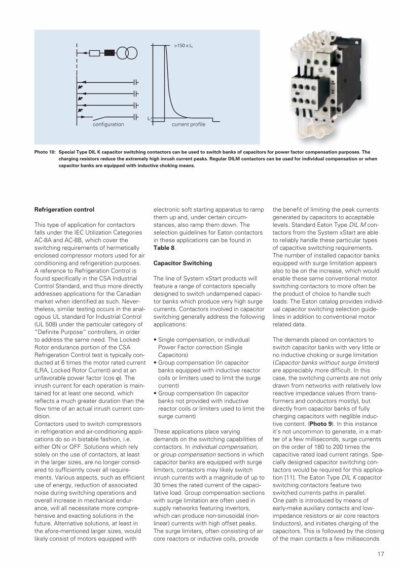
Photo 10: Special Type DIL K capacitor switching contactors can be used to switch banks of capacitors for power factor compensation purposes. The
charging resistors reduce the extremely high inrush current peaks. Regular DILM contactors can be used for individual compensation or when
capacitor banks are equipped with inductive choking means.
Refrigeration control
This type of application for contactors falls under the IEC Utilization Categories AC-8A and AC-8B, which cover the switching requirements of hermetically enclosed compressor motors used for air conditioning and refrigeration purposes. A reference to Refrigeration Control is found specifically in the CSA Industrial Control Standard, and thus more directly addresses applications for the Canadian market when identified as such. Never-theless, similar testing occurs in the anal-ogous UL standard for Industrial Control (UL 508) under the particular category of “Definite Purpose“ controllers, in order to address the same need. The Locked-Rotor endurance portion of the CSA Refrigeration Control test is typically con-ducted at 6 times the motor rated current (LRA, Locked Rotor Current) and at an unfavorable power factor (cos v). The inrush current for each operation is main-tained for at least one second, which reflects a much greater duration than the flow time of an actual inrush current con-dition. Contactors used to switch compressors in refrigeration and air-conditioning appli-cations do so in bistable fashion, i.e. either ON or OFF. Solutions which rely solely on the use of contactors, at least in the larger sizes, are no longer consid-ered to sufficiently cover all require-ments. Various aspects, such as efficient use of energy, reduction of associated noise during switching operations and overall increase in mechanical endur-ance, will all necessitate more compre-hensive and exacting solutions in the future. Alternative solutions, at least in the afore-mentioned larger sizes, would likely consist of motors equipped with
electronic soft starting apparatus to ramp them up and, under certain circum-stances, also ramp them down. The selection guidelines for Eaton contactors in these applications can be found in Table 8.
Capacitor Switching
The line of System xStart products will feature a range of contactors specially designed to switch undampened capaci-tor banks which produce very high surge currents. Contactors involved in capacitor switching generally address the following applications:
• Single compensation, or individual Power Factor correction (Single Capacitors)
• Group compensation (In capacitor banks equipped with inductive reactor coils or limiters used to limit the surge current)
• Group compensation (In capacitor banks not provided with inductive reactor coils or limiters used to limit the surge current)
These applications place varying demands on the switching capabilities of contactors. In individual compensation, or group compensation sections in which capacitor banks are equipped with surge limiters, contactors may likely switch inrush currents with a magnitude of up to 30 times the rated current of the capaci-tative load. Group compensation sections with surge limitation are often used in supply networks featuring invertors, which can produce non-sinusoidal (non-linear) currents with high offset peaks. The surge limiters, often consisting of air core reactors or inductive coils, provide
the benefit of limiting the peak currents generated by capacitors to acceptable levels. Standard Eaton Type DIL M con-tactors from the System xStart are able to reliably handle these particular types of capacitive switching requirements. The number of installed capacitor banks equipped with surge limitation appears also to be on the increase, which would enable these same conventional motor switching contactors to more often be the product of choice to handle such loads. The Eaton catalog provides individ-ual capacitor switching selection guide-lines in addition to conventional motor related data.
The demands placed on contactors to switch capacitor banks with very little or no inductive choking or surge limitation (Capacitor banks without surge limiters) are appreciably more difficult. In this case, the switching currents are not only drawn from networks with relatively low reactive impedance values (from trans-formers and conductors mostly), but directly from capacitor banks of fully charging capacitors with neglible induc-tive content. (Photo 9). In this instance it’s not uncommon to generate, in a mat-ter of a few milliseconds, surge currents on the order of 180 to 200 times the capacitive rated load current ratings. Spe-cially designed capacitor switching con-tactors would be required for this applica-tion [11]. The Eaton Type DIL K capacitor switching contactors feature two switched currents paths in parallel. One path is introduced by means of early-make auxiliary contacts and low-impedance resistors or air core reactors (inductors), and initiates charging of the capacitors. This is followed by the closing of the main contacts a few milliseconds
configuration current profile

18
later. The main contacts are now provid-ing the second current path, through which the capacitor rated current flows. As an added improvement to earlier designs, the capacitor switching contac-tors from the Eaton xStart generation no longer keep the pre-charging auxiliary contacts (from the first path) in the circuit when switching off the capacitors. This new feature effectively eliminates any possible thermal overloading of the con-tacts and of the associated surge limit-ers. The line of Eaton DIL K capacitor switching contactors is offered to accom-modate the most frequently encountered range of Capacitor Bank sizes used in such group compensation assemblies. (Table 8). IEC-Data for selecting contac-tor sizes can be referenced in [11].
Tungsten, Incandescent Lamps
From an electrical point of view, the switching of tungsten filament lamps or incandescent bulbs is really only a func-tion of the ohmic resistance involved. In the OFF or “cold“ state, the overall resis-tance of the lamp filament is relatively low. At the moment of switching on, this initial low resistance will lead to a momentary high inrush current which will quickly dissipate down to the rated cur-rent of the lamp once the resistance of the circuit path builds up as the filament gets hotter. On the average, the high instantaneous inrush currents generated by tungsten filament lamps can easily reach a momentary peak of at least 16 times the continuous current rating of the lamp.
When switching tungsten lamp loads, or for that matter any load with a high momentary inrush, careful consideration should be given in the design phase to the number of such loads which would be switched by a single contactor. The respective summation of inrush currents from all lamps would need to be taken into consideration and, whereas the con-tactor selected may be able to ade-quately handle the requirement, the high current peaks generated by a single switching operation could end up creat-ing undue burdens for the rest of the intallation. Dividing lamp loads into vari-ous sub-groups using a number of smaller contactors would represent a more benefical approach with respect to the overall functionality of the layout. For example, in the event of a fault, at least a portion of the lighting would still be func-tional if the overall load were to be shared by a greater number of devices. Refer to Table 8 for Selection guidelines on appropriate Eaton contactors for this application.
Ballast, Electrical Discharge Lamps
Electric Discharge Lamps encoutered throughout the industry are primarily of the High-Intensity Discharge Lamp vari-ety, the majority of which consist of Mercury Vapor Lamps, Metal Halide and High-Pressure Sodium lamps, as well as a number of additional types such as Electroluminescent and Low-Pressure Sodium Lamps. Not included in this cate-gory would be the more commonly known neon fluorescent lights (High volt-age lamps not covered as part of this paper). The main demands placed on electrical components for these types of lighting applications involve switching of the ballast necessary for the High Inten-sity Discharge lamps and the compensa-tion capacitors which may be involved in limiting ballast reactance levels. Capaci-tors will often be added to the ballast cir-cuit for this purpose, and must thus be taken into consideration when selecting a proper switching component such as a contactor. Ballasts essentially represent an inductive type load for a contactor. They produce the necessary voltage pulse to ignite the high intensity lamp discharge and they subsequently act to limit the current flowing through the lamp. It’s crucial for this current limita-tion to occur, otherwise the decreasing resistance of the gas medium would lead to increase current flow which would ultimately destroy the lamp. The process to select the proper ballast (pre-charging element) to match the charac-teristics of a particular type of HID lamp needs to be closely coordinated. Cur-rently, there are two distinct types of ballasts encountered: The more econom-ical electromagnetic type ballast, and the newer, more efficient electronic type ballast. According to available published literature, the energy saving potential of using an electronic ballast can be quite significant, up to at least 25% in many instances. The newer “Energy saving“ lamps are fluorescent types equipped with pre-charging, electronic type bal-lasts. There are many advantages associ-ated to the use of electronic ballasts, not the least among which is the beneficial effect to the human eye by reducing the amount of flicker normally produced by those lights. The electronic ballasts oper-ate at a much higher frequency than nor-mal supply network levels, and are thus able to significantly reduce the flickering effect. Both the European Union4 and the American government are taking strong steps to improve the efficiency of energy usage in commercial and indus-trial sectors in the coming years by mak-ing recommendations to replace electro-mechanical ballasts with more efficient
lighting solutions using electronic ver-sions. As mentioned, High Intensity Discharge Lamps are available in various forms and feature different operating characteris-tics. When first energized they will dis-play differing levels of inrush currents as well as duration times for the warm up and starting phases, possibly also involv-ing very high momentary surge currents in the millisecond range due to the use of charging capacitors. This type of parallel capacitive loading would be a crucial fac-tor in determining the ultimate rating of the contactor. Some High-Pressure-Sodium lamps as well as Mercury-vapor lamps employ the use of dispersion field transformers to mitigate the effect. For these types of lamps the starting phase can take as long as 10 minutes, during which time a current in the magnitude of 2.2 times the lamp’s rated current can flow. Three crucial aspects must conse-quently be observed in order to properly determine the ultimate rating of the con-tactor:
• Its continuous rated current and ther-mal loading capability,
• Its making capacity,• its making capacity for capacitive load
switching
These contactor parameters must never be exceeded. We are currently conduct-ing evaluation testing for specific lighting loads, the results of which will be pub-lished in an upcoming technical paper on the subject. These types of tests will pro-vide more precise selection data to deter-mine proper contactor sizes for lighting loads, than what is presently available using the NEMA General Purpose Tests referenced in Table 8.
In Electric Discharge Lamps the voltage level present at the lamp terminals will have a marked influence on the overall lamp temperature. This temperature can play a crucial role in its own right in cer-tain applications, such as promoting plant growth in commerical nurseries for example. Eaton has developed a line of
specialized type DIL L lighting contactors for this purpose, which feature a mark-edly reduced resistance across their con-tact surfaces combined with the capabil-ity to accommodate larger cross-sestions for conductor connection. Both design features act to significantly reduce the amount of voltage drop present on the lamp terminals. This also helps to achieve a more uniform distribution of maximum voltage levels throughout an installation, which is especially useful in applications involving numerous lamp loads.
19
Summary:
The most pertinent Special Purpose application test results achieved through extensive testing for our contactors are presented in Table 8. Test sequences to cover these various applications differentiate themselves mostly in the criteria established for the Overload and electrical Endurance por-tion of the testing. A standardized test to verify the dielectric integrity of the devices after testing is performed at a voltage level of 1000V + 2 x Un = 2200 V AC (since all Eaton contactors for the North American market are rated at a maximum voltage of Un = 600V.) The tested values are valid for 3 phase load-ing at the respective supply voltages indi-cated. It’s not possible to directly com-pare values tested in accordance with UL 508 and CSA C22.2 No.14 with those established per the IEC standards, or empirically transfer from one set of stan-dards to the other. The voltage difference alone, say between 400V and 480V, has an enormous impact on the switching capabilities of contactors from all manu-facturers. All the data presented, with the exception of “Capacitive Switching“, are covered with standard, off-the-shelf Eaton Type DIL M motor switching con-tactors. In order to switch capacitor banks of capacitors not equipped with surge current limiters, Eaton offers its line of specialized Type DIL K contactors, for both the IEC world and the North American market. Individual compensa-tion applications, as well as group com-pensation capacitor banks equipped with surge limitation, can be reliably handled on all continents by the conventional, and
more economical, Type DIL M motor switching contactors. Even those cus-tomers who aren’t exporting to North America can still benefit from the highly modernized advances and features offered by these products since all the Eaton contactors presented in this paper are world market devices which can be universally applied. The contactors are also CE marked and provided with IEC rating information in order to enable their export from North America to the rest of the world.
Validity:
The information contained herein was dutifully and thoroughly researched, but does not purport to serve as a substitute for the informational content of current and pertinent North American standards, since more detailed information is often required for comprehensive design and engineering purposes. At the time of print, all approval testing for the Eaton contactors and assemblies presented had been successfully completed, but the approval reports issued by the testing agencies were still in preparation.
Dipl.-Ing. Wolfgang EsserManager Product Support ICD-PSPIndustrial Control DevicesElectrical SectorEaton Industries GmbH, Bonn
With grateful acknowledgment of the support from:Mr. Andre R. Fortin, BA PhysInternational Corporate AdvisorCodes & Standards, Power ProductsHouston, TX, USA
References:
[1] Wolfgang Esser,xStart - The new Generation:100 Years of Moeller contactors- Continous Progress -VER 2100-937 GB,Moeller GmbH, Bonn, 2004Download: http://www.moeller.netQuicklink ID: 937en
[2] Wolfgang Esser “Modern Switching InstallationsEfficiently Fitted, and Wired Securely“VER 2100-938GBMoeller GmbH, Bonn, 2004Download: http://www.moeller.netQuicklink ID: 938en
[3] Wolfgang Esser “Special considerations governing
the application of Manual Motor Controllers and Motor Starters in North America”
Moeller GmbH, Bonn, 2004 VER1210-1280-928GB,
Download: http://www.moeller.netQuicklink ID: 928en
[4] UL 508, “Industrial Control Equipment”

Eaton is dedicated to ensuring that reliable, efficient and safe power is available when it’s needed most. With unparalleled knowledge of electrical power management across industries, experts at Eaton deliver customized, integrated solutions to solve our customers’ most critical challenges.
Our focus is on delivering the right solution for the application. But, decision makers demand more than just innovative products. They turn to Eaton for an unwavering commitment to personal support that makes customer success a top priority. For more information, visit www.eaton.com/electrical.
To contact an Eaton salesperson orlocal distributor/agent, please visitwww.eaton.eu/electrical/customersupport
Eaton Industries GmbH
Hein-Moeller-Str. 7–11D-53115 Bonn / Germany
© 2012 by Eaton CorporationAll rights reservedPrinted in Germany 08/12Publication No.: VER1200+2100-953GBip August 2012Article No.: 106649
Eaton is a registered trademark of Eaton Corporation
All other trademarks are property of their respective owners.
SmartWire-DT™ is a trademark of Eaton Corporation.