Motor Protection Application Guide - Your Power Control ... · PDF file1 Motor Protection...
28
Motor Protection Application Guide
Transcript of Motor Protection Application Guide - Your Power Control ... · PDF file1 Motor Protection...

Motor ProtectionApplication Guide

About the Authors
Paul Lerley has 28 years of utility and electronics experience, including 15 years at Central MainePower Company. He is a graduate of the University of New Hampshire and was Director of Substations Electrical Systems at Central Maine Power prior to joining Basler Electric Company. Mr. Lerley is a Senior Member of the IEEE and participates in four working groups of the Power System Relaying Committee. He has authored articles on testing for the Doble Engineering Conference and Transmission and Distribution magazine. He was previously very active in the Electric Council of New England. Mr. Lerley was Principal Application Engineer at Basler Electric from 1996 to 2000 and was a Planning Engineer at Central Maine Power from 2000 to 2010. He currently works for RLC Engineering as a Senior Power System Engineer.
Mike Young received his MBA from Rollins College in 1983 and BSET from Purdue University in 1971. He worked for Wisconsin Electric Power Company as a Relay Engineer for two years, and for Florida Power Corporation as a Field Relay Supervisor for 21 years. He authored the text "Protective Relaying for Technicians" and co-authored papers for the Georgia Tech Protective Relaying Conference. Mr. Young is a Regional Application Engineer for Basler Electric and is a member of the IEEE. Mr. Young retired from Basler Electric in 2002 and is President of North Idaho Relay Consulting.
Daniel (Dan) Ransom, PE has 40 years of industrial and utility electronics experience; including many years in motor protection development and application support for a major US relay manufacturer. He has extensive experience in consulting engineering for power and communications systems. Dan is an engineering graduate (BSEE) of Gonzaga University, Spokane, Washington; he also holds a liberal arts degree from Washington State University. He is a member of the IEEE IAS (Industry Applications), PES (Power Engineering), Communications, and Standards societies. To date he has one US patent. He is a Professional Electrical Engineer in 11 states, commonwealths, and territories across the United States. Dan joined Basler Electric in 2010 and is Principal Application Engineer for the West Coast region.
This document contains a summary of information for the protection of various types of electrical equipment. Neither Basler Electric Company nor anyone acting on its behalf makes any warranty or representation, express or implied, as to the accuracy or completeness of the information contained herein, nor assumes any responsibility or liability for the use or consequences of use of any of this information.
First printing April 1998Revision C.0 July 2013

1
Motor Protection Application Guide
1. Introduction
When applying protective relays to motors or any other equipment, the decision of how much protection is enough must be made. The answer depends on motor rewind cost, loss of production, effect of downtime, new versus old installation, metering, control, and the consequences of a motor failure on the electrical system and process.
This guide presents an overview of motor hazards and a discussion of detection and protection options. Typical setting value ranges for the Basler Electric BE1-11m protection system are given along with considerations to help designers and users when selecting Basler's motor protection solution.
Most of the protection functions apply to squirrel cage, wound, induction motors. Additional protection elements are needed for synchronous motors and are mentioned in this guide.
2. Overview of Motor Hazards
Motor protection is a challenge because many different incidents can affect a motor and the associated load. Motor hazards include the following:
Motor induced • High internal temperature • Insulation failure (faults within the motor) • Bearing failure • Mechanical failure • Failure to start • Synchronous motors - loss of field
Load induced • Overload and underload • Jamming • High inertia, especially at starting
Environment induced • High ambient temperature • High contaminant level or blocked ventilation • Extreme cold or wet conditions
Source induced • Loss of phase or phases • Voltage unbalance • Overvoltage • Undervoltage • Phase reversal • Out-of-step condition resulting from
system disturbance
Operation induced • Closing out of phase • High duty cycle • Jogging • Rapid reversing
3. Protection 3.1 Stator Faults
3.1.1 Phase Fault Overcurrent Protection: Choose the phase CT so the motor running mode full load amps (FLA) is no less than 50% of the rated phase CT primary. Ideally, the phase CT primary should be chosen so the FLA is 100% of the phase CT primary or slightly less, but never more.
Phase-to-phase and three-phase stator faults usually are detected with nondirectional, instantaneous elements. If the available three-phase fault current is a low multiple of the relay setting (weak system), quick pickup is not assured. In this situation, differential relaying should be considered (see Section 3.2). Otherwise, instantaneous phase overcurrent elements typically are applicable when the motor rating is less than one-half of the supply transformer kVA rating.

2
When an instantaneous element is used for stator faults the setting should be as low as possible, yet never operate during the starting period. The locked rotor amps (LRA), ILR is usually six times the full load amps (FLA), IFL. Fig. 1 illustrates the element settings in relation to the starting current and the FLA. The instantaneous phase element (50P) should be set at no less than 1.7 times the LRA (using the value of LRA at maximum starting voltage), plus a safety margin (1.25 pu plus relay accuracy (0.02). This setting assumes the element is sensitive to the transient overreach (DC offset) of an asymmetrical fault.
Lower settings are possible if the element disregards the transient component or if a time delay longer than the transient time (6-15 cycles) is added (50TP). Verify that the minimum available three-phase fault current at the motor terminals is at least 3 times the element setting. When applying a time delay ensure that all of the equipment can withstand the maximum available fault current for the total clearing time (element operation time, plus auxiliary time delay, plus circuit breaker operating
time). FIGURE 1. STATOR SHORT-CIRCUIT PROTECTION WITH 50 OR 50P ELEMENT.
3.1.2 Differential Protection: Differential protection is used on motors where the available short-circuit current is close to the value of LRA. It is also used on very large motors because of
its greater sensitivity. Differential protection is always preferred; however, it is generally more costly than instantaneous relaying because all six leads must be brought out of the motor and additional elements might be required.
Differential protection is selected over other methods because of its sensitivity, speed and security.
a) Self-balancing differential: The most economical approach is self-balancing differential as shown in Fig. 2. The cost for this method is reduced because only three CTs are required instead of the six CTs needed for larger motors with larger conductors. This differential requires one ring or doughnut CT per phase of sufficient diameter to accommodate conductors from both ends of the motor, as well as three 50 elements (one each per phase). This scheme is self-balancing and produces no current for starting or load variation and, because there is only one CT per phase, there is no concern about matching CT performance to eliminate unequal CT saturation. CT saturation is likely for large fault currents but is sufficiently slow to allow the instantaneous elements to operate.
FIGURE 2. SELF-BALANCING DIFFERENTIAL.

3
b) Percentage-restraint differential: An alternate form of differential protection uses six CTs, used especially on 1500-2500 HP and greater motors (see Fig. 3). Not all motors are built with access to both ends of the motor windings; in which case this type of differential protection cannot be used. Order the external neutral connections to implement differential protection.
Typically, all six CTs are the same ratio and accuracy class. When connecting the CTs, observe correct CT phasing as shown in Fig. 3. A motor relay with three, two-winding inputs can be applied. Ideally, equal currents flow in the restraint windings for normal load, starting and external faults. For internal phase or ground faults, all of the current will flow through the operate windings. The CTs do not always give the same secondary current for the same primary current because of variations in manufacturing and burden connections (meters, unequal lead lengths). For example, during a fault, non-identical error currents can flow because of dc offset so that the transient response in the CTs is not the same.
The differential function must be set above the maximum error current that can flow during an external fault; yet the element must be set below the minimum fault current that can flow during a winding fault. Using the percentage-differential relaying concept, the differential current required to operate the element is a percentage of the "through" or total restraint current. Modern motor relays often have separate settings for starting mode and running mode percentage differential slopes.
The scheme also protects for cable faults between the motor and the motor breaker (52) by using the line-side CTs of the breaker. If the motor and motor breaker are supplied separately, match the CT ratios and accuracy classes when specifying the equipment.
FIGURE 3. CONVENTIONAL PERCENTAGE-DIFFERENTIAL RELAYING.
3.1.3 Ground Fault Protection: a) Ground sensor 50G: Common causes of motor ground faults are damage to motor conductor insulation and internal shorts from moisture within the motor. The preferred and most sensitive method to detect stator ground faults is with a ground sensor CT. This scheme works particularly well with solidly grounded connections and also supplies good results in low-impedance grounded systems. See Fig. 4. All three-phase leads from the motor pass through the opening of a flux summation or toroidal current transformer supplying the instantaneous overcurrent 50G element shown in Fig. 4.
This arrangement leaves only the ground-fault zero-sequence currents in the CT. This CT has a maximum opening around 8 inches (20 cm) that prevents its use on larger motors. With a fixed ratio of 50:5 (regardless of the size of the motor) and a sensitive instantaneous overcurrent, the toroidal differential provides a pickup in the range of 4-12 amps. If more sensitive settings are required, add a time delay to avoid nuisance trips caused by zero-sequence cable capacitance current flow during external faults.
The ground fault sensor connection might be the only scheme providing sufficient sensitivity when the supply system is high-impedance grounded. If a large ground fault current is available in a solidly grounded system, the 50G element must operate before the low-ratio CT saturates. Fortunately, the high impedance of modern relays reduces the CT burden and alleviates this problem.

4
b) Residual ground connection 51N: For larger motors where the conductors will not fit through a ground sensor CT, the residual ground connection shown in Fig. 4 must be used. The ground fault element sensitivity is limited by the phase CT ratio. Because unequal CT performance is expected, the built-in timing of a 51 element avoids tripping on false residual current. This 51N element must be coordinated against the 51G system ground protection element (typically in the supply transformer neutral, if used). Set the 51N delay with sufficient time to override any spurious ground current that might be caused by switching or other system transients.
FIGURE 4. GROUND SENSOR ELEMENT (50G) AND RESIDUAL GROUND CONNECTION (51N AND 50N).
c) Ground fault 50N: In a residually connected, solidly grounded feeder application, where the ground fault is usually high and the CT quality is good (C-400 or better), an instantaneous element (50N) can be used for ground-fault tripping. The system is solidly grounded so a ground fault will draw current in the magnitude of a three-phase fault, per IEEE Standard C37.96. An alternate method is to set this element at 4 times FLA or greater to avoid tripping on starting.
3.2 Thermal Damage
When a motor stator winding is energized with the rotor at rest or "locked," stator winding currents can range from 3 to 7 times rated full-load value depending on motor design and supply system impedance. Heating in the stator
winding, proportional to I2t, is 9 to 49 times rated conditions and the winding is without benefit of the ventilation normally produced by motor rotation. Actual values of LRA are part of the motor data supplied by the motor manufacturer.
Depending on the design, a motor can be thermally stator limited or rotor limited during locked-rotor conditions. The motor manufacturer can furnish the allowable locked-rotor time only after the motor design is completed. This time is given as time at rated locked-rotor current starting from either rated ambient temperature (cold stall time) or rated operating temperature (hot stall time). These parameters are given as part of the motor time-current curve defined by IEEE Standard 620.
Starting times depend on motor design and load torque characteristics and must be determined for each application. Although starting times of 2 to 20 seconds are common, high-inertia loads might take several minutes to attain full speed. Starting time increases if bus voltage is less than nominal.
The starting current of a motor falls between the locked rotor value and the FLA when the rotor begins to turn. Therefore, stator heating decreases as the motor accelerates.
The motor thermal limits curve has three separate pieces and is based on the three running conditions of the motor (see Fig. 5, upper curve): • Locked rotor or stall condition • Motor acceleration • Motor running overload
For most motors the motor thermal limit curve is one smooth curve. In most cases manufacturers provide curves for both hot and cold motor conditions. Overloads must be below this motor thermal damage curve. However, especially in long starting, high-inertia motors, the starting thermal damage curve can have similar current as does the running (overload) mode thermal curve; leading to possible nuisance trip during starting. In this case, the starting thermal damage curve (locked rotor and acceleration) and the running thermal damage curves do not fit smoothly together. Modern motor protection relays use custom locked rotor and running (overload) curves to fit motor protection to these type of motor thermal limits.

5
Ieq = equivalent thermal current in pu (unit of thermal pickup current) I = maximum phase current in pu I1 = positive sequence fundamental component of current in pu I2 = negative-sequence fundamental component of current in pu k = constant to determine additional heating caused by negative-sequence current in pu
The factor k is a user setting. With k set to 8, the formula gives a derating factor closely matched to the NEMA MG1-2009 (Motor Guide) derating factor (from voltage unbalance). A larger k makes the estimation of equivalent current, Ieq more conservative. If k is set to 0, the motor relay uses maximum positive-sequence current only (I1max). Because voltage sensing is optional, the unbalance ratio of negative-sequence to positive-sequence current (I2/I1) is used instead of voltage unbalance.
The Basler thermal model implementation has two unique features. One is the ability to tailor the 49 thermal model pickup with the Overload (OL) setting. The range of this setting is 0.9-1.2. The normal thermal curve pickup is at service factor (SF) · FLA; with this setting the thermal curve pickup becomes OL · SF · FLA. Using this Overload setting, the thermal model pickup can be fine tuned for lightly or heavily loaded applications.
Another unique feature is the ability to set the thermal capacity at which the motor will perform an emergency start. This setting, Max Emergency Thermal Capacity, increases the trip point of the thermal model, thus keeping the process running. Once the emergency start is made, the thermal model adjusts to retain thermal data and thus protects the motor as the motor cools into the nominal thermal range. Most relay manufacturers do not provide this important protection.
b) RTD temperature biasing: RTD biasing modifies the thermal model by taking temperature data from the stator RTDs as additional inputs to the thermal capacity calculations. RTD biasing accounts for motor operation in high ambient temperatures or after experiencing a cooling loss.
4
FIGURE 5. MOTOR THERMAL CURVE LIMIT.
3.2.1 Thermal Overload Protection: The life of the motor is reduced if the winding temperatures exceed the designated insulation class levels for a significant time. Prolonged operation at 10°C above the design temperature limits reduces motor life by a factor of two. Motor thermal characteristics must be managed carefully.
a) 49 thermal model: A 49 thermal element creates a realistic thermal model of the motor because the 49 thermal element takes the load level and negative-sequence current into account. Thus, the thermal model creates an "equivalent current" Ieq that best represents the actual motor dynamics.
In particular, the thermal model calculation uses equivalent thermal current with unbalance biasing, the selected thermal curve, pickup current, motor cooling constant(s), RTD biasing based upon measured stator temperature, and the hot/cold safe stall ratio.
The equivalent thermal current, Ieq follows:
Formula 1 where,
Ieq= I 1+kI2
I1
2

6
Typically, three points are defined at Minimum RTD Bias Temperature, Center RTD Bias Temperature, and Maximum RTD Bias Temperature. Set the Minimum RTD Bias at ambient (40°C). A good starting point for the centerpoint Thermal Capacity (%TC) is the percentage difference between Hot Stall time and Cold Stall time. Later, this point can be modified from a learned observation and from motor monitoring. Determine centerpoint temperature from manufacturer's data: Temperature Rise of Stator times 10 percent margin plus the rated operation Ambient Temperature. Set the third and end point for maximum insulation temperature.
For example, if maximum insulation factor of the motor is F (most used), then 155°C and 100% TC is the end point of RTD biasing.
More than three points for RTD biasing can be set resulting in more motor productivity in high-temperature environments. Because thermal biasing is an exponential temperature phenomenon, the Basler BE1-11m provides more than three points for more accurate biasing.
c) RTD temperature sensing and voting: Motor relays monitor the RTD temperature data, usually six embedded in the stator windings (two per phase) and one or two on the motor bearings. The motor relay uses RTD voting to force concurrence among the different blocks of RTD data. For example, if stator RTD voting is set for 3, then 3 or more temperatures must exceed the pickup level before the relay takes action. With this setting, two RTDs can be malfunctioning and the motor relay continues to use correct temperature data.
Typically, the motor relay accepts two setting levels for each monitored point: a low setting for alarm and a high setting for shutdown. The specific settings are derived from the winding insulation class, defined in NEMA MG1, and judgment based on the plant operating conditions. The recommended setting for alarm temperature level is the sum of the maximum ambient, plus 10 degrees hot spot allowance, plus the full-load temperature rise. This value should be below the insulation class rating. The trip level should be at the insulation class temperature; however, this setting can be as much as 50°C above the class rating if the process is critical because the loss of life from occasional short overload periods is insignificant. Setting the trip temperature at the insulation class limit is a conservative setting.
Typically, motors are cooled by a rotor-mounted fan blade that forces air through the motor frame while the motor is running. Thermal limits and temperature rise are based on this cooling functioning as designed with a known level of ambient air temperature. If normal cooling is blocked, overheating at normal load current is possible. The only protection will be temperature-measuring devices located in the motor such as RTDs or thermocouples. The motor relay provides this protection with inputs from RTDs imbedded in one or more of the winding slots. With the Basler BE1-11m, thermocouples placed in the air plenum can be connected to 4-20 mA or 0-10 V transducer modules as inputs to the Remote Module (the Remote Module accepts both RTDs and analog inputs).
d) Traditional 51-element implentation: Older motor protection used 51 elements instead of the 49 thermal model and no RTD temperature data. Fig. 6 compares these two methods of motor protection, IEEE device numbers (51 or 49). These devices might have nearly identical static characteristics but differ greatly in their dynamic response; therefore, in their ability to track the motor temperature over time.
FIGURE 6. THERMAL OVERLOAD - RUNNING.

7
To force the static characteristic to pass through point P in Fig. 6, the time dial in a 51 element or the time constant in the 49 thermal element is adjusted. The dynamic response of a 51 element is linear and uses uncompensated motor current, whereas the 49 thermal model has an exponential response and uses the equivalent current, Ieq.
Running mode thermal overload can be provided by an overcurrent element 51P that has a time-current characteristic similar to the thermal overload limit. The minimum pick up of this 51P element is the continuous overload specification of the motor, i.e., FLA · SF. The characteristic is usually an I2t curve. The time dial is chosen to coordinate against the thermal limit (Point P) and allow short duration overloads predictable from the process analysis.
Fig. 7 compares the 51 element and the 49 thermal model response for motor current step changes. The 49 thermal model element performs better, especially when the process requires tolerating temporary overloads. The 49 thermal mode element "remembers" the work (heat) in the motor; the 49 element does not reset to zero when the current is below the overload limit as does the 51 element (see the 2400 second area). Instead, the 49 thermal model element settles at a value corresponding to the thermal capacity (TC) at the given load level.
FIGURE 7. COMPARE 49 THERMAL MODEL ELEMENT AND 51L DYNAMIC RESPONSE.
The 51 element tends to trip faster than the 49 thermal model and complete motor usage is not attained. With the 49 thermal model element, more work is obtained from the motor without damage (see the 6400 second area). However, the 51 element can serve as a backup to the 49 thermal element. The 49 thermal model gives a more accurate presentation of motor operation and heating.
3.2.2 Locked Rotor Protection: The motor relay thermal model provides locked rotor protection because of the rapid heating that occurs in a motor that does not transition from starting mode to running mode in sufficient time (acceleration too long). Backup to the thermal model is shown as a 14 speed switch input (see Fig. 8). The speed switch is set at 10%-50% of full speed. Use a timer with the speed switch so that the motor trips if shaft rotation does not reach set rotational speed within the starting period.
FIGURE 8. LOCKED ROTOR PROTECTION.
Failure to accelerate to running mode can also be protected by using the 48 element. This element is a timer that starts when a motor starts and trips if the timer setting is exceeded prior to the motor reaching the running mode. Motor start and motor run signals are provided to the element. The 48 time setting must be set to a time a little longer (2-5 seconds) than the typical start time of the motor and no longer the maximum hot stall time.

8
The 51P element is a time-overcurrent element set for backup of the running mode thermal overload. Primary protection is from the thermal model. The failure to accelerate is detected by the thermal model, with backup from the overload 51P element (set for running mode) shown in Fig. 8, as well as 14 and 48 elements.
For some large induction motors with low starting voltages or with high-inertia loads and long starting times, the starting time can exceed the allowable locked-rotor time without excessively heating the rotor. Make initial settings for the thermal model and backup elements, if used, then examine motor start reports and learned starting parameters to optimize locked rotor protection. The 48 element and the 14 speed switch are particularly helpful for high-inertia (long) starts. For high inertia, prolonged starting, set the 48 incomplete sequence element to a time slightly longer than the actual start time; the thermal model will recognize that the motor shaft is turning and starting current is dropping. Because the motor shaft is turning there is motor cooling. Another method is to use a 14 speed switch. The speed switch trips a motor start effort if no or insufficient shaft turning has occurred within a preset time delay.
3.2.3 Repetitive Starts and Jogging Protection: In repeated starting and intermittent operation, very little heat is removed by the cooling medium produced by a turning rotor. Repeated starts can build temperatures to dangerously high values in either stator or rotor windings unless sufficient time is provided to allow the heat to dissipate.
The NEMA MG1 Sections 12.54, 20.12, and 21.12 provide guidelines for typical installations. These standards allow two starts in succession, coasting to reset between starts with the motor initially at ambient temperature, and for one start when the motor is at a temperature not exceeding its rated load operating temperature. This best practice assumes that the applied voltage, frequency, load torque during acceleration, method of starting, and load inertia are all within motor design. The application and protection of motors having abnormal starting conditions must be coordinated with the data from the manufacturer. The motor relay uses manufacturer's data such as hot cold stall time and the cooling time constants to the 49 thermal model to help limit excessive starting.
Modern motor relays include a protective element for thermal overload protection. Unlike an inverse-time electromechanical counterpart, this relay tracks the stored value of the "thermal capacity". Motor starting alone can use 50%-65% of the available thermal capacity. The thermal-model motor relay also recognizes that a stopped motor cools more slowly than a running motor because there is no cooling air produced by the rotor. Therefore, it is possible that attempting to start a motor twice in rapid succession might cause a protective trip on thermal overload. Although provision is made for emergency starting (to continue or save a valuable process), the manufacturer's recommendation for frequent starts should be used.
The motor relay also provides Starts Per Time Interval, Time Between Starts, Time Since Last Start, and Time Since Last Trip. Select a setting for number of starts and time to match manufacturer recommendations. Exact determination of starting occurrences is a very complex calculation that is affected by many factors including motor size, enclosure, voltage, ambient temperature, inertia, load-speed-torque characteristic, and running time. Typically, motor restarts depend more on the stator thermal capacity than on rotor thermal capacity and stall time. The best rule, by far, is to minimize the number of starts because each start reduces the life of the motor.
3.2.4 Unbalance Protection: a) Cause and effects: Unbalance in the
feeder phase voltages or motor winding impedance causes unbalanced currents to flow to the motor. These currents can cause more damage than symmetrical faults or balanced three-phase starting or running abnormalities. The negative-sequence current I2 from the unbalance causes rotor heating and additional copper losses in the stator windings because of increased line current flow at 120 Hz. The resulting I2R loss raises the motor temperature quickly. Rotor structural damage is common when the protective relaying does not operate quickly for unbalanced conditions.
b) Detection: The low negative-sequence motor impedance causes the amount of negative-sequence current to be typically about five times larger than the amount of negative-sequence voltage. Also, the negative-sequence

9
voltage (V2) measurement yields very different results depending on the location. Although the current unbalance is the parameter directly responsible for the temperature increase in the motor, two detection methods are available: voltage and current unbalance.
Two common measuring techniques have been implemented:
• NEMA defined unbalance• Negative-sequence measurement
The NEMA definition, found in MG1 Section 21.29.2 is percent voltage unbalance = 100 · (maximum voltage deviation from average voltage) / average voltage.
3.2.5 Voltage Sensing (47) or Phase Reversal: Voltage sensing element 47 can be connected to a bus or at the motor. In present usage, this protection commonly detects gross wiring errors like a phase reversal or an open phase. Connecting a 47 element to a bus on which many motors have connection has the advantage of detecting the unbalance voltage for a complete set of motors, but has the disadvantage of tripping all motors when an unbalance occurs. Slight bus voltage unbalance can be tolerated by a motor if its load is lighter at the time of the unbalance.
3.2.6 Voltage Unbalance Element:a) Motor terminal application: Voltage
unbalance 47 protection can be applied at the motor terminals or at the motor bus (preferred). NEMA MG1 20.24 and 21.29 recommend that continuous voltage unbalance should never exceed 5%. For small to moderate unbalance, the NEMA and negative-sequence formula yield approximately the same result. If used, a voltage unbalance element can be set at a maximum pickup of 5%. To set the time delay to trip, consider the thermal damage by the corresponding negative-sequence current. This voltage unbalance of 5% corresponds to an I2 of about 25%, provided the voltage is measured at the motor terminals. Assuming the motor can tolerate I2t = tun, the maximum time delay for a 5% voltage unbalance and tun = 40 would be 640 seconds. Although no standard exists for motors, a value of tun = 40 is often used.
Most motor protection relays do not offer the 47N element with an extremely inverse characteristic that could emulate the I2t
characteristic (the Basler BE1-11m can perform voltage inverse-time curves and is a unique exception). If the timing curve is inverse, the time dial should be selected to cause tripping when the voltage unbalance at the motor terminals, corresponding to the 1 pu I2, is equal to 20%.
Base the time delay on the worst case expected unbalance, i.e. open phase in the motor feeder cable. The positive and negative-sequence currents are then equal (1pu at full load). The trip time for this unbalance condition would thus be equal to tun (I2 =1pu). For tun = 40, the maximum delay for an open phase should be 40 seconds. If the element uses a definite time, this point needs to be the setting and result in overprotection, if the unbalance is less severe.
b) Motor bus application: In most applications, the voltage seen by the 47N will not come from the motor terminal, but from the bus. Depending on the size and nature of other loads connected to the bus, the 47N might not sense the open phase in the motor feeder. Therefore, 47N application requires careful consideration, as well as backup from current-based protection 46. This situation is the reason voltage-based unbalance protection has become a phase-reversal or phase-loss protection with high settings (50%).
3.2.7 Current Unbalance: Current unbalance (46) is measured in the motor feeder itself and has the advantage of being applied at each motor. It is easy to implement in multifunction motor relays like the BE1-11m. Measuring algorithms include the true negative-sequence measurement and the difference between the maximum and minimum phase currents.
To relate the current unbalance setting to the 5% NEMA voltage unbalance limit, it is necessary to establish the correlation between the current unbalance algorithm and the unbalanced voltage. For a negative-sequence type element, the I2 percent setting is approximately 4 to 5 times the percent voltage unbalance for the worst case nominal load condition.

10
The current unbalance measuring elements have an I2
2t = k characteristic that makes the time delay settings easier to apply than with the voltage element. If no other information is available, choose k = 40. The worst-case unbalance occurs for an open phase at full load. The negative-sequence current is then equal to the positive sequence current, i.e. 1 pu. The time dial should be set to cause tripping in 40 seconds in this case where k = 40.
For current unbalances it is common to provide an alarm first so that corrective action can be taken before removing the motor from service. This element is an inverse-time overcurrent element (51) using negative-sequence as the operating quantity. The curve characteristic should be a straight line on log-log scales, emulating the I2t = k, and should be set to match the motor running mode characteristic. The Basler BE1-11m has many current elements and thus can provide multiple timing and alarm levels.
3.3 Abnormal Supply
According to the NEMA MG1, Part 20.14., motors are expected generally to operate successfully under running conditions at rated load with a variation of plus or minus 10% of rated voltage, plus or minus 5% of rated frequency, or a combination of the two, provided the sum of the absolute values of the deviations does not exceed 10% and the frequency variation does not exceed plus or minus 5%. For synchronous motors, rated excitation current must be maintained. Fig. 9 shows the effects of voltage and frequency variations on induction motor characteristics.
Given these limits, there is no single protective device that can make a direct determination of these quantities simultaneously. However, variations in voltage or frequency will result usually in an increase in stator winding temperature over a long period. The 49 thermal model as well as direct temperature measuring devices, such as RTDs, will detect these changes
FIGURE 9. THE EFFECTS OF VOLTAGE AND FREQUENCY VARIATION ON INDUCTION-MOTOR CHARACTERISTICS.
11
and provide warning or tripping, provided the abnormal condition is not extreme. Voltage and current elements provide abnormal supply protection for extreme cases.
A large induction motor rotating at rated speed or a large synchronous motor with fixed excitation can be approximated at steady-state conditions as a constant kilovoltampere device for a given shaft load; therefore, current variations follow voltage variations inversely. An undervoltage condition will result in an overcurrent condition. Single-phase over- or undervoltage is likely to be detected by unbalanced voltage or current protection if so equipped. Three-phase undervoltage is protected by thermal overload protection because the current will be greater than normal for a given load.
Voltage elements, as previously mentioned, are not always sufficiently selective to provide reliable protection, especially on buses where several motors are connected because the spinning motors will support the voltage on the low or missing phase. However, an inverse time or definite time undervoltage (27) element, active only in the running mode, is recommended to trip when a prolonged undervoltage condition exists and as a backup. Pickup settings of 0.85 per unit will provide adequate protection. The time delay should be set to ignore transient voltage dips (100 ms).
A separate concern of undervoltage is its impact on starting a motor. Unlike a running motor, low voltage on starting of a motor produces lower starting current and, hence, lowers torque. If the torque is too low to overcome the torque requirements of the load, the motor will not start successfully. The motor relay uses an undervoltage element 27 to check the supply voltage before starting, active only in starting. If the voltage is too low the element prevents starting. Pickup settings of 0.7 per unit will provide adequate protection with no time delay.
3.3.1 Loss-of-Potential Element: Having accurate potential readings at the motor relay is necessary to determine whether a voltage unbalance condition is actual or is the cause of a blown sensing fuse. Losing a sensing fuse can cause a motor to trip offline if the motor relay does not have fuse loss protection, a 60FL
element, to block unwanted tripping. The 60FL element detects fuse loss and loss of potential by using voltage and current thresholds that are expressed as a percentage of the nominal voltage and current values. Upon detection of a fuse loss condition, 60FL will block voltage elements selected by the user such as 27/59 positive-, negative- and zero-sequence elements.
The 60FL element also provides an alarm that can be mapped as a Major or Minor alarm for immediate maintenance inspection. If the voltage elements are not blocked and are allowed to falsely trip the protected motor, serious "process" consequences may result. Modern motor protection relays like the Basler BE1-11m offer this protection.
3.3.2 Voltage Drop During Starting: Another concern during motor starting is the voltage drop caused by the LRA flowing through the supply transformer, especially for across-the-line (ATL) starts. A weak system or undersized supply transformer worsens the situation. When the supply voltage decreases during start, then so do the current and starting torque. If there are other running motors on the bus, the reduced voltage causes greater currents and further increases the voltage drop. Should the voltage drop sufficiently low it is possible for the motor torque to be too low and prevent a successful motor start.
Whether motor starting or system weakness is the problem, reduced voltage can cause trouble at times other than during acceleration. Reduced voltage in running mode will cause overheating with time. Short-term voltage dips might cause an already running motor to stall. The effect of trying to start more than one motor at the same time should be considered since it will increase the undervoltage condition. Many motors use motor contactors powered by the ac line voltage. Reduced voltage could drop out the motor contactor and cause an already running motor to drop off line when the motor contactor drops out. The Basler BE1-11m provides custom curves with voltage dependency to accommodate lowered-voltage starting.
To avoid these problems, perform voltage-drop calculations to determine the motor voltage conditions during starting. Check the calculations at maximum and minimum expected bus voltage before start. In a properly designed
12
power system, with a good match between bus and motor design voltages, starting voltage dips of 15% are common. Designers frequently assume that an accelerating motor draws its full voltage inrush current and calculate the upstream voltage drops on that basis. Clearly, any voltage drop in the supply system means that full voltage and corresponding inrush current cannot be present.
3.3.3 Overvoltage: Overvoltage conditions can stress the motor winding insulation and decrease motor life. Induction motors experience a slight increase in efficiency when the motor is running in an overvoltage condition. Motor slip decreases and is inversely proportional to the square of the voltage. The current decreases as well as the power factor. Because of I2t , temperature also decreases.
However, most new motor designs are close to the flux saturation point; thus increasing the voltage increases the V/Hz ratio and could cause air gap flux saturation resulting in excess motor heating. The motor relay thermal element detects this heating and eventually trips the motor. Faster reaction comes from setting an overvoltage element (59). Referencing NEMA MG1 Part 14.33, set the overvoltage element to alarm at 10% greater than nominal voltage. Set the time delay for 100 ms to avoid nuisance alarms.
3.3.4 Reduced-Voltage Starting: Employ reduced-voltage starting techniques when voltage drops are excessive during starting. These add to the motor controls but might be less expensive than increasing transformer and cable sizing. All of these techniques use some method to apply partial voltage to the motor during the initial starting sequence, then when the motor is at partial speed, full voltage is applied to finish the start sequence. Modern motor relays support reduced-voltage starting. Use different settings groups to optimize protection for each operation mode.
Wye-Delta starting applies a reduced voltage at the beginning of the start sequence with a wye connection of the motor and then changes to the delta connection for the motor to complete the start sequence. This arrangement reduces starting torque and voltage drop on the motor bus.
Another method of reduced voltage starting is autotransformer start. The autotransformer is connected in wye with the supply voltage and the tapped partial voltage is applied to the motor during starting mode. When the starting contactor makes its transition, the partial voltage source is opened and full supply voltage is applied.
3.3.5 Frequency Protection: Frequency in excess of 5% over the rated frequency without a corresponding voltage increase is not considered to be a hazardous condition for synchronous or induction motors provided the driven equipment does not overload the motors at the greater frequency.
At decreased frequency without a corresponding voltage drop, the flux requirements of a motor are increased, thus increasing the hysteresis and eddy current losses and heating. Sustained operation at 5% below nominal frequency and rated or overvoltage is not permissible per NEMA MG1, Part 20.14. Protection against this type of operation can be thermal overload or RTD temperature measurement. In addition, more refined protection can be obtained with the 81 underfrequency elements in fully featured motor relays. Time delay settings of 10-30 seconds allow the motor to ride though transient conditions without nuisance tripping.
Many utility substations are equipped with underfrequency (UF) load shedding relays to reduce the system load during a loss of generation and subsequent decay in system frequency. Large motor loads connected to the distribution substation might interfere with the normal operation of the underfrequency relay by showing a decline in frequency without a complete loss of voltage. This situation can happen when the distribution bus is disconnected from the supply transformer and the underfrequency (UF) relay(s) is connected to the distribution bus. The UF relay then sees the residual voltage from the motor load and might operate incorrectly. Relocating the underfrequency voltage transformer to the high side of the supply transformer or adding additional time delay to the underfrequency time delay usually solves the problem.

13
3.4 Mechanical or Process ProtectionGenerally, we think of protective relays
as devices that protect electrical equipment (motors, breakers, etc.). However, in the case of motor protection there are times when it is more important to protect the process.
3.4.1 Undercurrent (37) (Loss of Load): Some pump motors use the pumped fluid for cooling and a sudden loss of current indicates an immediate cooling loss, causing process disruption and possible motor damage.
For example, a water pumping station operates continuously at 90% of FLA. If the pump is damaged, lost its prime, or the shaft broke, the load on the motor is drastically reduced. In this case an undercurrent element (37) is valuable. This element is not in service until the motor is in running mode and set to detect loss-of-load conditions to alarm or trip from 50%-70% of FLA. Set a time delay to ride through temporary supply fluctuations (100 ms).
3.4.2 Underpower Protection (32): The underpower protection element can be set to be more sensitive than the 37 undercurrent element for process-related loss of load problems.
3.4.3 Jam Protection: Motor process such as chippers and shredders can become jammed. The motor relay enables jam protection in running mode only. This protection detects stalls when the load torque exceeds the breakdown torque and causes its speed to decrease to zero or near zero. This situation occurs when the applied shaft load is greater than the producing motor torque. This condition will develop motor current equal to or approaching locked-rotor current, and some reduction in terminal voltage depending upon the motor impedance. According to NEMA MG1, the maximum stall time must be marked on the motor name plate. Set jam protection with an instantaneous overcurrent element (50) at 70% of LRA. Time delay at this current should be instantaneous.
3.4.4 Bearing Protection: To minimize damage caused by bearing failure, protective devices can sound an alarm or de-energize the motor. Bearing protective devices respond to one or more of the following conditions: (1) Low oil level in reservoir: (71) level
switch (2) Low oil pressure: (63) pressure switch
(3) Reduced oil flow: (80) flow switch (4) High temperature: (38) thermocouples (5) Rate of temperature rise (6) Vibration (used on motors with
anti-friction bearings in place of thermal devices)
Usually, resistance temperature detectors
(RTDs) monitor large motor bearings and are used as one of the inputs to the motor relay. Dual-set points of the RTD function allows for alarm and trip settings at two different temperatures.
Unlike many motor relays, the Basler BE1-11m motor relay includes 4-20 mA or 0-10 Vdc analog transducer inputs in the Remote Modules to bring these signals and other process transducers back to the motor relay. In this manner the motor relay directs and modifies the production process, acting to replace a PLC (programmable logic controller).
4. Bus Transfer and Reclosing
Many motor buses are critical to process or plant operation; therefore, they must be maintained if at all possible. For static loads, high-speed reclosing or transfer to an alternate source is appropriate. However, motor loads require special considerations. When the motor is disconnected from the voltage supply, the voltage at the motor terminals does not go to zero. The machine generates a voltage at its open-circuited terminals that decays with time. A fast reclose applies the full bus supply voltage in series with the residual motor voltage, producing a total winding voltage that can be dangerously high. Capacitors in the circuit make the situation worse because capacitors support the voltage level.
A second complication is the decay in motor speed with respect to the supply system. The frequency of the residual voltage in the motor will be a decaying frequency value as the motor begins to slow. The worst case could be a nearly 2.0 per unit voltage and 180° out-of-phase condition with the supply voltage. The possibility of damage exists for local reclosing of the motor, high-side reclosing from the utility, transferring to an alternate source, or reduced-voltage motor starting. A Basler BE1-11 protection system with
sync-check capability or the BE1-700V relay can be utilized for this application. The safest restart method is with motor re-energization after some dead time, but other considerations apply.
4.1 Parallel Transfer
Parallel transfer is a method of transferring process loads from one source to an alternate source. In this method, the bus-tie breaker is closed before the normal source breaker is opened. This method has gained wide acceptance because the transient on the motor bus is eliminated, assuming the two sources are in phase.
However, the bus system designed for this transfer method might violate the interrupt rating for the circuit breakers and the short-term withstand ratings of the normal and alternate source power transformers. A fault in a motor or its leads occurring during the time the sources are paralleled might produce fault current levels in excess of the circuit breaker ratings. The probability of this happening is small; however, the consequences of such a fault should be thoroughly understood before the parallel transfer system is used.
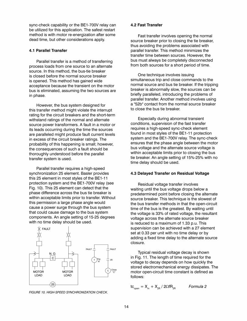
Parallel transfer requires a high-speed synchronization 25 element. Basler provides this 25 element in most styles of the BE1-11 protection system and the BE1-700V relay (see Fig. 10). This 25 element can detect that the phase difference across the bus tie breaker is within acceptable limits prior to transfer. Without this permission a large phase angle would cause a power surge through the bus system that could cause damage to the bus system components. An angle setting of 15-25 degrees with no time delay should be used.
FIGURE 10. HIGH-SPEED SYNCHRONIZATION CHECK.
14
4.2 Fast Transfer
Fast transfer involves opening the normal source breaker prior to closing the tie breaker, thus avoiding the problems associated with parallel transfer. This method minimizes the transfer time between sources. However, the bus must always be completely disconnected from both sources for a short period of time.
One technique involves issuing simultaneous trip and close commands to the normal source and bus tie breaker. If the tripping breaker is abnormally slow, the sources can be briefly paralleled, introducing the problems of parallel transfer. Another method involves using a "52b" contact from the normal source breaker to close the bus tie breaker.
Especially during abnormal transient conditions, supervision of the fast transfer requires a high-speed sync-check element found in most styles of the BE1-11 protection system and the BE1-700V relay. The sync-check ensures that the phase angle between the motor bus voltage and the alternate source voltage is within acceptable limits prior to closing the bus tie breaker. An angle setting of 15%-25% with no time delay should be used.
4.3 Delayed Transfer on Residual Voltage
Residual voltage transfer involves waiting until the bus voltage drops below a predetermined point before closing the alternate source breaker. This technique is the slowest of the bus transfer methods in that the open-circuit time of the bus is the greatest. By waiting until the voltage is 33% of rated voltage, the resultant voltage across the alternate source breaker is reduced to a maximum of 1.33 p.u. This supervision can be achieved with a 27 element set at 0.33 per unit with no time delay or by adding a fixed time delay to the alternate source closure.
Typical residual voltage decay is shown in Fig. 11. The length of time required for the voltage to decay depends on how quickly the stored electromechanical energy dissipates. The motor open-circuit time constant is defined as follows:
tcopen = Xm + X2R / 2ΩfR2R Formula 2

15
where: f = frequency Xm = per unit magnetizing reactance of the motor X2R = per unit rotor reactance at running speed R2R = per unit rotor resistance at running speed
At a value of one time constant, the voltage will have decayed to 36.8 percent of its initial value. Each successive time constant will drop the voltage and additional 36.8 percent until no voltage remains.
A safe value of residual voltage is considered 0.33 per unit per ANSI and IEEE. Meeting that requirement requires a delay in circuit reclosure of at least two time constants.
When auto-reclose of the motor feeder or auto-reclose of the utility source takes place, the phase angle residual voltage considerations should be used.
FIGURE 11. DECAY OF OPEN CIRCUIT VOLTAGE AND PHASE ANGLE.
Either the motor should be disconnected prior to reclose by using a frequency element, or the reclose should be delayed until the voltage has decayed to 0.33 per unit.
When it is better to protect the motor load from being re-energized out of phase or with high residual voltage rather than reclosing or transfering the motor load, a frequency element (81) set at 97%-98% of rated frequency with a time delay of 10-20 cycles will protect the motor by detecting any underfrequency condition as the motor is decelerating and trip the supply breaker. The time delay needs to be shortened if high-speed reclosing is in use. The same element can be used for automatic load shedding of the motor at abnormally low frequencies. In both cases potential transformers must be located between the motor supply breaker and the motor leads.
For synchronous motors, reclosing must not be permitted until proper resynchronization can be performed. Arrange to trip the supply breaker with an undervoltage or underfrequency relay or element and reconnect with a 25 synchronization element.
5. Synchronous Motors
Protection of the synchronous motor is similar to that of the induction machine with additional requirement for protection against the following conditions: • Loss of field • Out-of-step conditions
The field usually has its own protection for loss-of-field or field undervoltage. Small synchronous motors can be protected against loss of excitation by an additional low-set undercurrent (37) element connected to the field circuit (not the running mode 37 element). This element should have a time delayed drop-out to avoid nuisance tripping.
Also, power factor relay (55) can be used to detect an out-of-step or loss of excitation condition in a synchronous motor. When the motor loses synchronism or loss of field, watt flow weill be produced out of the motor and VAR flow into it. A short time delay is typical, and the relay is generally not in service until the motor is running at synchronous speed.
6. Typical Protection for Motors
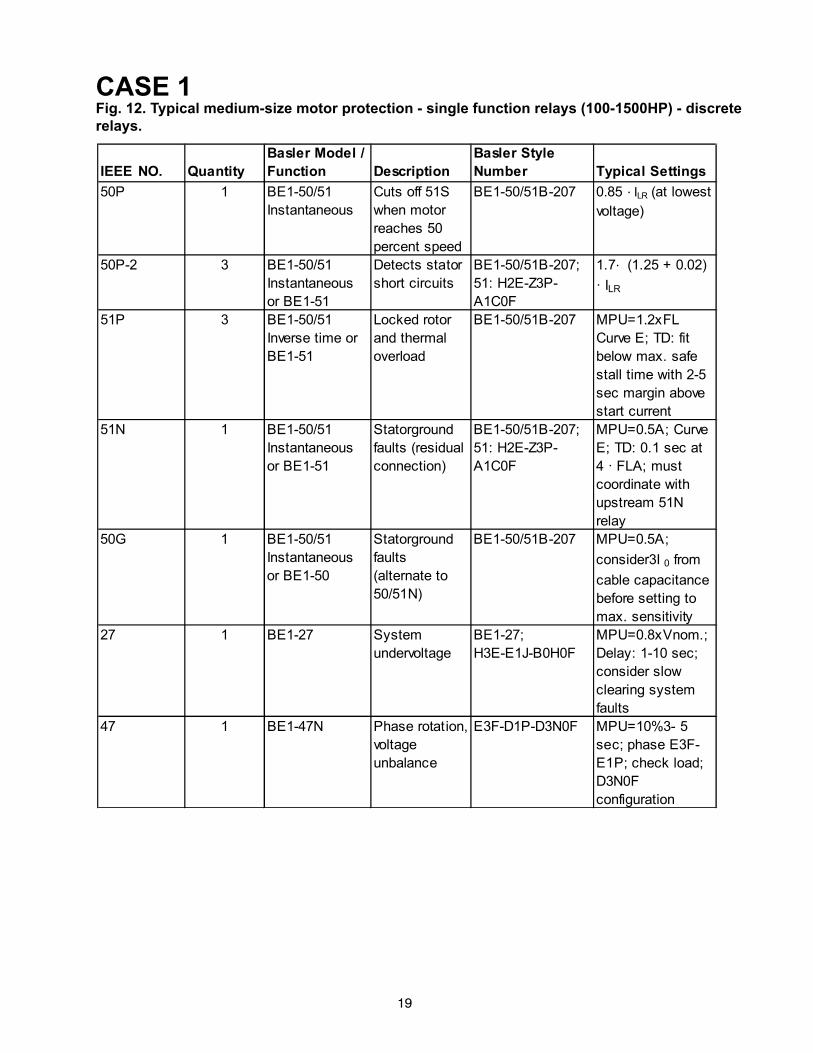
Case 1: Small-to-medium size motor (100-1500 HP)
Single-Function Relays (Old Method, Not Recommended)
This example specifies the relay selection and typical settings for motors in the 600-1500 HP range. This range is selected as the medium-size motor class. Cost and process considerations will ultimately determine the choice of protection level.
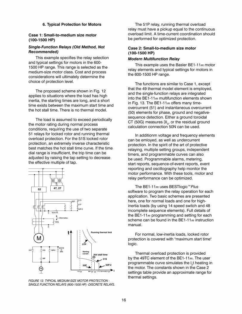
The proposed scheme shown in Fig. 12 applies to situations where the load has high inertia, the starting times are long, and a short time exists between the maximum start time and the hot stall time. There is no thermal model.
The load is assumed to exceed periodically the motor rating during normal process conditions, requiring the use of two separate 51 relays for locked rotor and running thermal overload protection. For the 51S locked rotor protection, an extremely inverse characteristic best matches the hot stall time curve. If the time dial range is insufficient, the trip time can be adjusted by raising the tap setting to decrease the effective multiple of tap.
FIGURE 12. TYPICAL MEDIUM-SIZE MOTOR PROTECTION - SINGLE FUNCTION RELAYS (600-1500 HP) -DISCRETE RELAYS.
16
The 51P relay, running thermal overload relay must have a pickup equal to the continuous overload limit. A time-current coordination should be performed for optimized protection.
Case 2: Small-to-medium size motor (100-1500 HP)Modern Multifunction Relay
This example uses the Basler BE1-11m motor relay elements and typical settings for motors in the 600-1500 HP range.
The functions are similar to Case 1, except that the 49 thermal model element is employed, and the single-function relays are integrated into the BE1-11m multifunction elements shown in Fig. 13. The BE1-11m offers many time-overcurrent (51) and instantaneous overcurrent (50) elements for phase, ground and negative-sequence detection. Either a ground toroidal CT (50G) measures 3I0, or the residual ground calculation connection 50N can be used.
In additionm voltage and frequency elements can be emloyed, as well as undercurrent protection. In the spirit of the art of protective relaying, multiple setting groups, independent timers, and programmable curves can also be used. Programmable alarms, metering, start reports, sequence-of-event reports, event reporting and oscillography help monitor the motor performance. With these tools, motor and relay performance can be optimized.
The BE1-11m uses BESTlogic™Plus software to program the relay operation for each application. Two basic schemes are presented here, one for normal loads and one for high-inertia loads (by using 14 speed switch and 48 incomplete sequence elements). Full details of the BE1-11m programming and setting for each scheme can be found in the BE1-11m instruction manual.
For normal, low-inertia loads, locked rotor protection is covered with "maximum start time" logic.
Thermal overload protection is provided by the 49TC element of the BE1-11m. The user programmable curve simulates the I2t heating in the motor. The constants shown in the Case 2 settings table provide an approximate range for thermal settings.

17
As stated in NEMA MG1, Part 21.29.1.2, the existence of unbalanced voltage feed results in four to ten times the current imbalance. Part 20.24 of the NEMA guide states that negative-sequence voltage unbalances should not exceed 5%. Current unbalance (46) detection provides rotor thermal protection. One method is accomplished with a negative-sequence (51Q) element and setting the pickup in amperes to approximately 5 times the product of maximum continuous voltage unbalance (pu) times the FLA. The time dial is set to cause tripping in K (the assumed I2
2t value) seconds for I2 equal to FLA.
FIGURE 13. TYPICAL SMALL TO MEDIUM SIZE MOTOR PROTECTION - MULTIFUNCTION RELAYS (100-1500 HP).
Another variation uses a 50 element with I2 as the input, with a time delay. This application uses negative-sequence current as the input to a 50 overcurrent element to sense unbalance conditions. For conservative protection choose 4 times 5%, which is 20% imbalance. Set the element for Mode I2 with a pickup of 20% and a delay of 10 seconds to avoid nuisance trips. Because the heating is slow (motor mass is large) a 10-second time delay is appropriate.
For locked rotor protection during high inertia, prolonged starting set the 48 incomplete sequence element to a time slightly longer than the actual start time. Alternately, or as a backup
method, a 14 speed switch can be used. The speed switch trips a motor start effort if no or insufficient shaft turning has occurred within a preset time delay.
Case 3: Differential protection for medium and large motors (> 600 HP)
This protection uses the Basler BE1-11m motor protection systems's percentage restraint differential protection.
When using differential (87) protection, plan to incorporate six-phase CTs with matching characteristics, so for lower operation currents (during the running mode) percentage Restraint Slope 1 can be smaller. However, during the starting mode, CT saturation is large. To avoid false trips during starting, choose a large Restraint Slope 2 for security.
Synchronous motors benefit from using the 40 and 55 functions. The 40Q function is available in the BE1-40Q relay. The 40 element functions on an abnormally low value or failure of machine field current.
The 55 element operates an excessive value of the reactive component of armature current, indicating abnormally low field excitation.
FIGURE 14. COMPREHENSIVE DIFFERENTIAL PROTECTION FOR MEDIUM AND LARGE MOTORS (GREATER THAN 600 HP).

18
7. Bibliography
1) Guide for AC Motor Protection, ANSI/IEEE Standard C37.96-2000.
2) Blackburn, J.L. and Domin, T.J., Protective Relaying Principles and Applications, CRC Press, 2007.
3) Hornak, D. L. And Zipse, D. W., Automated Bus Transfer Control for Critical Industrial
Processes, IEEE Transactions on Industry Applications, Sept/Oct 1991.
4) Motor Guide, NEMA Standard MG1-2009.5) Nailen, R. L., Motors, Electric Power
Research Institute, 1989.
6) Dymond, J. H., Stall Time, Acceleration Time, Frequency of Starting: The Myths and the Facts, IEEE Transactions on Industry Applications, Jan/Feb 1993.
7) IEEE Guide for the Presentation of Thermal Limit Curves for Squirrel Cage Induction
Machines, IEEE Standard 620-1996. 8) Boothman, D. R., Thermal Tracking - A Rational Approach to Motor Protection,
IEEE Power System Relay Committee, Jan 1974.
9) Horowitz, S. A. and Phadke, A. G., Power System Relaying, Research Studies Press, Ltd., 1995.
19
CASE 1Fig. 12. Typical medium-size motor protection - single function relays (100-1500HP) - discrete relays.

20
CASE 2Fig. 13. Small to Medium Size Motor, 100-1500HP Modern Motor Relay (Recommended)
IEEE NO. Quantity
Basler Model /
Function Description Basler Style Number
Typical Settings
(Primary)
50-1 1 BE1-11m Stator short
circuits
BE1-
11M5A1M1H2N0E000
Consult Instruction
manual and
BESTCOMSPlus®
software. Add
optional protection
as desired.
50-2 1 Stator Ground
protection
4 · FLA or greater
49TC 1 Thermal Model
protection
Choose curve or
create custom
curve to coordinate
with motor damage
curve
49TC Bias 1 Bias thermal
mode for high
ambient operation
Choose curve table
points; see above
discussion.
49RTD 6 Stator block Set voting to at
least 2.
49RTD 2 Bearing block Set voting to at
least 2.
49RTD 1 Ambient Set voting to 0.
27P-1 1 Low-voltage
starting
protec tion
0.7 pu · bus
voltage nominal
27P-2 1 Running m ode
voltage dropout
protec tion
0.85 pu · bus
voltage nominal
81-1 1 Underfrequency 0.95 pu · nominal
system frequency
81-2 O verfrequency 1.05 pu · nominal
system frequency

21
CASE 2 (continued)
IEEE NO. Quantity
Basler Model /
Function Description Basler Style Number
Typical Settings
(Primary)
47 Phase rotation,
voltage
unbalance
0.2 · bus voltage
46 (50-3) Current
unbalance
Use I2 (negative
sequence
current); 0.2 ·FLA: with a time
delay of 10,000ms
50-4 Running
overload
IEEE C37.96,
1.15 pu to 1.25
pu of SF · FLA
37 Undercurrent
(process
control sudden
loss of load)
50-5 Jam (running) 0.7 pu · LRC; no
time delay
66 Starts per
interval
Consult m otor
m anufac turer
data
48 Incom plete
sequence
Tim e greater
than norm al
s tarting plus
2-4 s .
14 Speed sw itch
(optional, high-
inertia s tarts ;
locked rotor
protec tion)

CASE 3Fig. 14. Differential Motor Protection, > 600HP, Modern Motor Relay.Add the 87 element to Case 2.
22
IEEE NO. Quantity
Basler
Model /
Function Description Basler Style Number
Typical Settings
(Primary)
87 1 BE1-11m Percentage
Restraint
Six CTs
BE1-
11M6D1M1J2P0E000
Consult
Instruction manual
and
BESTCOMSPlus
software.

NOTES

NOTES

NOTES

Revised 7/13