Motor Condition Monitoring Device - · PDF file1 New Product Motor Condition Monitoring Device...
22
1 New Product Motor Condition Monitoring Device K6CM Quantifying the status of a three-phase induction motor and pump. The alarm output threshold default is set. You can customize the value according to the site. As for comprehensive current diagnosis, the degradation can be detected comprehensively by combining each motor part and the load side. The insulation resistance of the three- phase induction motor and pump can be measured with current flowing (the secondary side leakage current of the inverter can also be detected). Features • Since the condition of the motor can be displayed in numeric values on the LCD, the motor condition can be checked without a dedicated tool. • The alarm output settings can be made according to the device, with reference to the threshold value that has already been set by default. • Depending on the threshold value setting for alarm output, the condition of the motor can be displayed on an alarm bar in three colors; Green (normal), Orange (warning), and Red (critical). • Equipped with a transistor output that externally outputs the status of the motor and error states of the K6CM main unit. • Monitoring can be performed easily on the PC by EtherNet/IP communication and a dedicated tool. • The numeric values of vibrations, temperature, insulation resistance, and current can be monitored by the same dedicated tool. • The trend of the motor condition can be monitored by a dedicated tool, and thus indications of a degradation can be monitored. • Clamp-type CT/ZCT that supports easy post installation. With a clamp-type CT/ZCT, the device can be installed without changing or removing the existing wiring, which makes post-installation easy. • Comes with the self-diagnosis function of the main unit internal circuit and analog sensing circuit. • Push-in Plus Terminal Technology reduces wiring work (double-insertion holes for crossover wiring). • UL listed for easy shipping to North America (ZCT (IRT) is UL recognized). * ZCT (IRT) is compatible with UL Recognition For the most recent information on models that have been certified for safety standards, refer to your OMRON website. Windows is a registered trademark of Microsoft Corporation in the United States and or other countries. EtherNet/IP TM is the trademarks of ODVA. Other company names and product names in this document are the trademarks or registered rademarks of their respective companies.
Transcript of Motor Condition Monitoring Device - · PDF file1 New Product Motor Condition Monitoring Device...
1
New Product
Motor Condition Monitoring DeviceK6CM
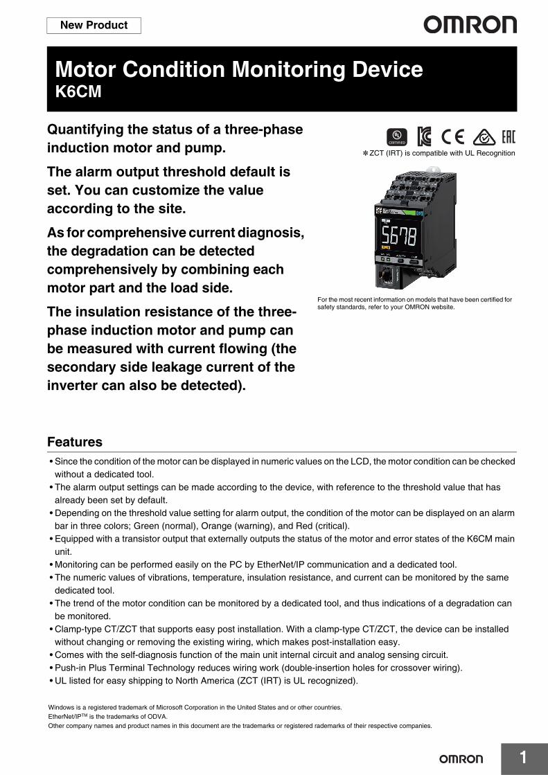
Quantifying the status of a three-phase induction motor and pump.
The alarm output threshold default is set. You can customize the value according to the site.
As for comprehensive current diagnosis, the degradation can be detected comprehensively by combining each motor part and the load side.
The insulation resistance of the three-phase induction motor and pump can be measured with current flowing (the secondary side leakage current of the inverter can also be detected).
Features• Since the condition of the motor can be displayed in numeric values on the LCD, the motor condition can be checked
without a dedicated tool.• The alarm output settings can be made according to the device, with reference to the threshold value that has
already been set by default.• Depending on the threshold value setting for alarm output, the condition of the motor can be displayed on an alarm
bar in three colors; Green (normal), Orange (warning), and Red (critical).• Equipped with a transistor output that externally outputs the status of the motor and error states of the K6CM main
unit.• Monitoring can be performed easily on the PC by EtherNet/IP communication and a dedicated tool.• The numeric values of vibrations, temperature, insulation resistance, and current can be monitored by the same
dedicated tool.• The trend of the motor condition can be monitored by a dedicated tool, and thus indications of a degradation can
be monitored.• Clamp-type CT/ZCT that supports easy post installation. With a clamp-type CT/ZCT, the device can be installed
without changing or removing the existing wiring, which makes post-installation easy.• Comes with the self-diagnosis function of the main unit internal circuit and analog sensing circuit.• Push-in Plus Terminal Technology reduces wiring work (double-insertion holes for crossover wiring).• UL listed for easy shipping to North America (ZCT (IRT) is UL recognized).
* ZCT (IRT) is compatible with UL Recognition
For the most recent information on models that have been certified for safety standards, refer to your OMRON website.
Windows is a registered trademark of Microsoft Corporation in the United States and or other countries.EtherNet/IPTM is the trademarks of ODVA.Other company names and product names in this document are the trademarks or registered rademarks of their respective companies.

K6CM
2
System ConfigurationBasic Configuration
*2. For details, refer to the technical data on page 16.
Dedicated tool
EtherNet/IP
Object monitored
K6CM-VBS1 (pre-amplifier)
K6CM-VBM
1 m (extendable to 100 m)
2.6 m
Single-phase power supply
Output signal (transistor output)
Measurement trigger signal
Built-in EtherNet/IP port
LAN
Note: Even without a computer, the alarm bar of the main unit notifies you of changes of motor state.
By keeping a computer or PLC continuously connected, you can monitor the state of a motor.
Sensor head
Connector
Tighten screw perpendicularly directly above rotation shaft (load side)
0.3 m
Inverter *1
Three-phase power supply (pre-wired cable)
(pre-wired cable)
Vibration & temperature monitoring type (K6CM-VB)
*1. Using an inverter helps prevent motor deterioration.In the conditions below, acceleration fluctuations tend to occur more frequently.• The frequency is stable at an inverter drive frequency of 50
Hz or higher.• The inverter carrier frequency is stable at 12.5 KHz or higher.
Test in the actual installation environment before use.
Dedicated tool
LAN
EtherNet/IP
Built-in EtherNet/IP port
Object monitored
Inverter secondary-side voltage
K6CM-ISM
1 m (extendable to 100 m)
Single-phase power supply
Output signal (transistor output)
Inverter (measurement is also possible with an inverter)
Three-phase power supply
40 m max. (From ZCT to motor. Extendable in some conditions) *2
Note: Even without a computer, the alarm bar of the main unit notifies you of changes of motor state.
By keeping a computer or PLC continuously connected, you can monitor the state of a motor.
7.5 kW or less(Measurement error increases when this value is exceeded.)
RST
(pre-wired cable)
(pre-wired cable)
1 m
Insulation resistance monitoring type (K6CM-IS)Three-phase, three-conductor, S-phase ground

K6CM
3
Dedicated tool
LAN
EtherNet/IP
Built-in EtherNet/IP port
Object monitored
K6CM-ISM
1 m (extendable to 100 m)
Single-phase power supply
Output signal (transistor output)
40 m max. (From ZCT to motor.Extendable in some conditions) *1
Note: Even without a computer, the alarm bar of the main unit notifies you of changes of motor state.
By keeping a computer or PLC continuously connected, you can monitor the state of a motor.
ST
R
N
7.5 kW or less(Measurement error increases when this value is exceeded.)
When an inverter is used with three-phase, four-conductor, N-phase ground, correct measurement is not possible
Note:
(pre-wired cable)
1 m
(pre-wired cable)
Three-phase, four-conductor, N-phase ground
*1. For details, refer to the technical data on page 16.
Comprehensive current diagnosis type (K6CM-CI)
Dedicated tool
LAN
EtherNet/IP
Object monitored
Single-phase power supply
Measurement trigger signal
K6CM-CIM
K6CM-CIC (CT)Any type of single-phase measurement
Three-phase power supply
Note: Even without a computer, the alarm bar of the main unit notifies you of changes of motor state.
By keeping a computer or PLC continuously connected, you can monitor the state of a motor.
0.75 kW to 300 kW (400 V)0.75 kW to 150 kW (200 V)
Built-in EtherNet/IP port
2.9 m
Output signal (transistor output)
Inverter *2 (Measurement is also possible without an inverter)
(pre-wired cable)
*2. When an inverter is used, the Degradation level may increase even with a normal motor. Adjust the alarm threshold to match the installation environment.

K6CM
4
Ordering InformationList of Models
Input partVibration & temperature sensor (Order separately)
Note: The vibration and temperature sensor consists of a sensor head and a pre-amplifier.A magnet is provided for the easy attachment of the vibration and temperature sensor.
ZCT (IRT) (Order separately)
Note: ZCT (IRT) is the abbreviation for Zero Current Transfer (Insulation Resistance Transfer).A cable for connection is provided with the ZCT (IRT).
CT (Order separately)
Note: A cable for connection is provided with the CT. Select a CT that sets the current of the applicable motor within the measurement range.To calculate the current, refer to Comprehensive Current Diagnosis Type Technical Data (Reference) on page 17.
EtherNet/IP communication cable recommended partsUse a Category 5 or higher STP cable (shielded twisted pair cable).
* It is recommended to use the cable and connector in combination described above.
Monitoring type Power supply voltage Model
Vibration & temperature type100 to 240 VAC K6CM-VBMA-EIP
24 VAC/VDC K6CM-VBMD-EIP
Insulation resistance type100 to 240 VAC K6CM-ISMA-EIP
24 VAC/VDC K6CM-ISMD-EIP
Comprehensive current diagnosis type100 to 240 VAC K6CM-CIMA-EIP
24 VAC/VDC K6CM-CIMD-EIP
Appearance (pre-amplifier)
Appearance (head) Attachment part Applicable Relay Model
M6 screw K6CM-VBM K6CM-VBS1
Rated voltage Through hole dia. (mm) Applicable Relay Model
200 to 480 VAC 52 dia. K6CM-ISM K6CM-ISZBI52
Rated primary-side current Applicable Relay Model5 A
K6CM-CIM
K6CM-CICB00525 A K6CM-CICB025
100 A K6CM-CICB100200 A K6CM-CICB200400 A K6CM-CICB400600 A K6CM-CICB600
Part name Manufacturer ModelCable Hitachi Metals, Ltd. NETSTAR-C5E SA 0.5 × 4P *
RJ45 connector Panduit Corporation MPS588-C *

K6CM
5
Industrial switching hub (recommended parts)
List of CombinationsAs for the K6CM, it is necessary to provide a combination of a vibration and temperature sensor, ZCT (IRT), and CT for the main unit and each model.One sensor must be provided for one main unit.
❍: Can be combined, ---: Cannot be combined
Product name Appearance
Specifications
ModelFunction No. of ports
Failure detection function
Industrial switching hub
Priority control (QoS): EtherNet/IP control data priorityFailure detection: Broadcast storm /LSI failure detection10/100BASE-TX, Auto-Negotiation
3 × W4S1-03B
5 × W4S1-05B
5 ❍ W4S1-05C
State monitoring componentsK6CM-VBMA-EIP/K6CM-VBMD-EIP
K6CM-ISMA-EIP/K6CM-ISMD-EIP
K6CM-CIMA-EIP/K6CM-CIMD-EIP
Vibration & temperature sensor
K6CM-VBS1 ❍ --- ---
ZCT (IRT) K6CM-ISZBI52 --- ❍ ---
CT
K6CM-CICB005 --- --- ❍
K6CM-CICB025 --- --- ❍
K6CM-CICB100 --- --- ❍
K6CM-CICB200 --- --- ❍
K6CM-CICB400 --- --- ❍
K6CM-CICB600 --- --- ❍

K6CM
6
Ratings and SpecificationsList of ModelsRatings
Power Supply
Power supply voltage K6CM-@@MA: 100 to 240 VAC, 50/60 HzK6CM-@@MD: 24 VAC, 50/60 Hz, 24 VDC
Allowable operating voltage range 85% to 110% of power supply voltage
Power supply frequency range 45 to 65 Hz
Power consumption
K6CM-VBM@24 VAC/24 VDC: 3.8 VA/2.1 W max.100 to 240 VAC: 7.1 VA max.
K6CM-ISM@24 VAC/24 VDC: 3.7 VA/2.0 W max.100 to 240 VAC: 6.2 VA
K6CM-CIM@24 VAC/24 VDC: 3.1 VA/1.6 W max.100 to 240 VAC: 6.0 VA max.
Input
Vibrations (vibration sensor)
Detection frequency 10 Hz to 10 kHz
Max. operating acceleration 10 G
Insulation resistance (ZCT (IRT))
Rated input voltage (Line voltage) 200 to 480 VAC, 50 Hz/60 Hz
Rated path current 300 AAC
Current, comprehensive current diagnosis (CT)
Rated input current 5 A, 25 A, 100 A, 200 A, 400 A, 600 A
Applicable motor type Three-phase induction motor
Outputs
Output relays Transistor output (N.C. contact)
Output relays 3-point
Output rating Rated voltage: 24 VDCMax. current: 50 mA, DC
Ambient operating temperature -10 to +55°C (with no condensation or icing)
Storage temperature -20 to +65°C (with no condensation or icing)
Ambient operating humidity 25% to 85% RH (with no condensation)
Storage humidity 25% to 85% RH (with no condensation)
Case color Black
Case material Polycarbonate UL94-V0
Altitude 2,000 m max.
Applicable wires Stranded wires, solid wires, or ferrules
Applicable wire size 0.25 to 1.5 mm2 (AWG24 to 16)
Wire insertion force 8 N max. (AWG20)
Screwdriver insertion force 15 N max.
Wire stripping length 8 mm
Recommended flat-blade screwdriver XW4Z-00B (Omron)
Current capacity 10 A (per pole)
Number of insertions 50 times
Weight Approx. 200 g
Mounting Mounts to DIN Trackscrew mounting
Dimensions 45 (W) × 90 (H) × 90 (D) mm
Setting method Communication settings from a dedicated tool via EtherNet/IP
Other functions Display value selection, self-diagnosis error output, setting value initialization, operation integration
Accessories Operation manual, CD-ROM (Motor condition monitoring Tool)

K6CM
7
Characteristics
*1. For details, refer to the technical data on page 16.*2. MS: Product status display, NS: Network status display.
Measurement range
K6CM-VB Acceleration: Up to 9.99 G, Velocity: Up to 45 mm/s,Motor temperature: 0 to 80°C, Differential temperature: 0 to 80°C
K6CM-IS Insulation resistance: 0.000 M to 1.000 MΩ,Leakage current: 0.00 mA to 200.0 mA
K6CM-CI
CurrentRating 5 A: 1.00 to 5.00 ARating 25 A: 5.0 to 25.0 ARating 100 A: 20.0 to 100.0 ARating 200 A: 40.0 to 200.0 ARating 400 A: 80.0 to 400.0 ARating 600 A: 120.0 to 600.0 ADegradation level: 0 to 999
Measurement absolute accuracy
K6CM-VBAcceleration ±3 dB±2 digit
Temperature Motor temperature: ±3°C±2 digit (±6°F±1 digit)Temperature Gap: ±6°C±2 digit (±12°F±1 digit)
K6CM-IS Insulation resistance
±35% rdg±2 digit (when the insulation resistance is 0.2 MΩ max.), when a 200-V/7.5-kW max. motor is used *1±35% rdg±2 digit (when the insulation resistance is 0.4 MΩ max.), when a 400-V/7.5-kW max. motor is used *1
K6CM-CI Current ±1.0% FS±1 digit (excluding CT variation)
Sampling cycleK6CM-VB Acceleration: 50 ms, Velocity: 0.5 s, Temperature: 0.5 s
K6CM-IS Normal mode: 10 s, Inverter special measurement mode: 60 s
K6CM-CI Comprehensive current diagnosis: 5 s, Current: 5 s
Moving average frequency 1, 2, 4, 8, 16, 32 times
External trigger(Excluding K6CM-IS)
External contact input specification
Short-circuit: Residual voltage 1.5 V max.Open: Leakage current 0.1 mA max.
Current during short-circuiting Approx. 7 mA
Transistor outputContact configuration: NPN open collector (normal close)Rated voltage: 24 VDC (maximum voltage: 26.4 VDC)Max. current: 50 mA, DC
Alarm
Parameters that can be output
K6CM-VB: Acceleration, Velocity, motor temperature, Temperature GapK6CM-IS: Insulation resistanceK6CM-CI: Degradation level, current
Expression method Transistor output, alarm bar
Setting value Same as the measurement range
Hysteresis 10% width of setting value
Reset method Manual reset/automatic reset (switchable)* Manual return method: Press the ALMRST button
LCD display 7-Segment digital display and single-shot displayFont height 14 mm
Applicable standards
Conforming standards EN61010-2-030Installation environment: Pollution degree 2, overvoltage category II, measurement category II
EMC EN61326-1(EMI: Class A EMS: Industrial Location)Acceleration ± 0.1G, Velocity ±2.25mm/s, Temperature ± 6°C, insulation resistance ± 35% rdg, current ± 10% F.S.
Safety standards
UL61010-2-030 (listing)Korean Radio Waves Act (Act 10564)RCMEAC
Insulation resistance
20 MΩ min.Between all external terminals and the caseBetween all power supply terminals and all other terminalsBetween all sensor connection terminals and trigger input terminal + output terminal + all EtherNet/IP ports
Dielectric strength
2,000 VAC for 1 minuteBetween all external terminals and the caseBetween all power supply terminals and all other terminalsBetween all sensor connection terminals and trigger input terminal + output terminal + all EtherNet/IP ports
Vibration resistance Vibration frequency 10 to 55 Hz, slice amplitude 0.35 mm in each of X, Y, Z directions 5 minute × 10
Shock resistance 100 m/s2, 3 times each in 6 directions along 3 axes
Degree of protection IP20
LED displayAlarm bar Red/Orange/Green
MS, NS *2 Red/Green
Ethernet communication
Communication protocol EtherNet/IP
Physical layer 100BASE-TX
Transmission distance 100 m (Distance between hub and node)

K6CM
8
Input partVibration & temperature sensorRatings
Characteristics
Item Model K6CM-VBS1
Power supply voltage Supplied from K6CM-VBM
Sensor head Max. acceleration 10 G
Ambient operating temperature Pre-amplifier: -10 to +55°C (with no condensation or icing)Sensor head: -10 to +80°C (with no condensation or icing)
Storage temperature Pre-amplifier: -20 to +65°C (with no condensation or icing)Sensor head: -20 to +90°C (with no condensation or icing)
Ambient operating humidity 25% to 85% RH (with no condensation)
Storage humidity 25% to 85% RH (with no condensation)
Altitude 2,000 m max.
Case color Pre-amplifier: BlackSensor head: Silver
Case material Pre-amplifier: Polycarbonate UL94-V0Sensor head: Aluminum alloy (ADC12) / Zinc die casting (ZDC2) (the threaded part is Steel (S45C))
Weight Pre-amplifier: Approx. 210 g (including cables)Sensor head: Approx. 40 g (including cables)
MountingPre-amplifier: DIN rail mounting, screw mountingSensor head: Screw mountingBetween pre-amplifier and sensor head: Connector connection (smart click connector)
Wire length Between pre-amplifier and sensor head: 2.6 m+0.3 m (cannot be extended)Between pre-amplifier and main unit: 1 m Can be extended up to a maximum length of 100 m
Item Model K6CM-VBS1
Measurement range Specified in main unit “Characteristics”
Applicable standards
Conforming standards
EN 61010-2-030Installation environment: Pollution degree 2, overvoltage category II, measurement category II
EMC EN 61326-1 (EMI: Class A EMS: Industrial Location)
Safety standardsUL 61010-2-030 (listing)RCMEAC
Insulation resistance 20 MΩ min.
Dielectric strength 500 VAC for one minute
Vibration resistance
Pre-amplifier Vibration frequency 10 to 55 Hz, slice amplitude 0.35 mm in each of X, Y, Z directions 5 minute × 10 sweeps
Sensor head Vibration frequency 10 to 55 Hz, slice amplitude 0.35 mm in each of X, Y, Z directions 5 minute × 10 sweeps
Shock resistancePre-amplifier 100 m/s2, 3 times each in 6 directions along 3 axes
Sensor head 100 m/s2, 3 times each in 6 directions along 3 axes
Degree of protection
Pre-amplifier IP20 (excluding the sensor-side cable)
Sensor head Conforming to IP67G (JIS C 0920 : 2003, Appendix 1)
LED display Pre-amplifier PWR: Green, ERR: Red, COM: Orange

K6CM
9
ZCT (IRT)Ratings and Specifications
CTRatings and Specifications
*1. Select a CT that brings the current of the applicable motor into the measurement range.To calculate the current, refer to the technical data on page 17.
*2. When using a flat wire, be sure to refer to the external dimensions drawing of the CT before selection on page 15.
Item Model K6CM-ISZBI52
Construction Indoor split type
Rated path current 300 A
Through hole dia. 52 mm dia.
Rated voltage 200 to 480 VAC, 50 Hz/60 Hz three phase
Measurement range Specified in main unit “Characteristics”
Measurement accuracy Specified in main unit “Characteristics”
Voltage input terminal 3-terminal lead wire, Length: 1m (pre-wired cable)
Output terminal 4-terminal lead wire, Length: 1m (pre-wired cable) Available wire length 100 m max.
Applicable standards
Conforming standards
EN 61010-2-030Installation environment: Pollution degree 2, overvoltage category II, measurement category II
EMC EN 61326-1 (EMI: Class A EMS: Industrial Location)
Safety standards
UL 61010-2-030 (Recognition) + CSA C22.2 No. 61010-2-030RCMEAC
Insulation resistance Between Mounting bracket - Secondary winding: 100 MΩ min.
Dielectric strength Between Mounting bracket - Secondary winding: 2000 VAC, 1 minute
Ambient operating temperature -10 to +55°C (with no icing)
Ambient operating humidity 25 to 85% RH
Weight Approx. 2.3 kg (including cables)
ModelItem K6CM-CICB005 K6CM-CICB025 K6CM-CICB100 K6CM-CICB200 K6CM-CICB400 K6CM-CICB600
Construction Indoor split type
Primary-side rated current 5 A 25 A 100 A 200 A 400 A 600 A
Measurement range *1 1 to 5 A 5 to 25 A 20 to 100 A 40 to 200 A 80 to 400 A 120 to 600 A
Secondary-side rated current Dedicated current
Secondary winding 3000 turns 6000 turns 9000 turns
Applicable frequency 10 Hz to 5 kHz
Insulation resistance Between output terminal and case: 50 MΩ min.
Dielectric strength Between output terminal and case: 2,000 VAC, 1 minute
Protective element 7.5 V clamp element
Permissible attachment/removal frequency 100 times
Attachable wire diameter *2 7.9 mm dia. max. 9.5 mm dia. max. 14.5 mm dia. max. 24.0 mm dia. max. 35.5 mm dia. max.
Operating temperature / humidity range -20 to +60°C, 85% max. (with no condensation)
Storage temperature / humidity range -30 to +65°C, 85% max. (with no condensation)
Supplied cable length 2.9 m (pre-wired cable)
Supplied cable terminal
Main unit side Ferrule terminal
CT side Round terminal

K6CM
10
Motor condition monitoring Tool (Software included with main unit)Operating Environment
Functions/Specifications (For more details, refer to the catalog of each product.)
* One vibration and temperature type, one insulation resistance type, and one current comprehensive diagnosis type can be set for one motor.
Element Specification
Supported OS Windows 7, Windows 8.1, Windows 10 (32 bit/64 bit) (Japanese/English)
.NET .NET Framework 4 and .NET Framework 3.5
CPU 1 GHz or more, 32 bit or 64 bit processor
Memory 1 GB or more, or 2 GB or more (for 64 bit)
HDD Available space of 16 GB or more, or 20 GB or more (for 64 bit)
Others Since this software is provided on a CD-ROM, a CD-ROM reading device must be available.If data is to be collected, a LAN I/F must be available.
Item Specification
Project Number of files that can be created No limit
ImportSupported format CSV data format
Measurement interval that can be imported 1 second to 99999 second (one-second step)
Number that can be registered in one project
Number of motors (device groups) 10
Number of devices per motor (device group) 3 *
Graphic displayType of graph Line graph
Display period 1 hour, 1 day, 1 month, 3 months, 6 months, 1 year, 2 years, 5 years, 10 years, 20 years

K6CM
11
Connection DiagramTerminal Diagram (Main Unit)
1 2 73 4 9
810
13 1415 1617 18
(2) Power voltage
A: 100 to 240 V AC D: 24 V AC/DC
1 2 1 2(No polarity)
(1) External trigger input
VB or CI: Function exists
IS: No function
Do not use
Do not use
7 89 10
(1) Sensor input
VB: Vibration and temperature sensor input
IS: ZCT (IRT) input
K6CM-VBS (pre-amplifier)
7 89 10
K6CM-ISZ(ZCT(IRT))
7 8
CI: CT input
K6CM-CIC(CT)
Output function
Transistor output
13 14
Interior
15 16
Interior
17 18
Interior
k l
Red/white
Black/white
Black
Red Red/white
Black/white
Black
Red
3 4
0 V5 V 680 Ω
Comparator+−
K6CM- VB M A -EIP(1) (2)

K6CM
12
Nomenclature
Note: Warning: Indicates that it is time for maintenance.Critical: Indicates that it is time for replacement.
* Trigger modes other than external triggerAlways: Trigger is not used. Measurement/monitoring are performed continuously after the power of the K6CM unit is turned on.Internal trigger: Measurement/monitoring starts based on the relation between the measured value and set value (trigger level).
You can use "Trigger Type" to specify whether measurement/monitoring start and continue for a set time when the measured value is over, or under, the set value (trigger level), or are executed while the measured value exceeds the set value (trigger level).
Name Meaning
Alarm barA bar on which the color of the emitted light changes according to the alarm status.
It is indicated in the following colors during measurement/monitoring. Green: Alarm status (normal)Orange: Alarm status (Warning)Red: Alarm status (Critical)
The alarm bar is lit out in each of the following states:When the power is OFF, when measurement is not being performed, and when a self-diagnosis error has occurred, etc.
Measurement type
Indicates the type of the measured value being displayed. The type can be switched each time the [DISP] key is pressed on the front operation part.
K6CM-VB “G”: Acceleration, “mm/s”: Velocity, “T”; Motor temperature,“ T”: Temperature Gap (difference between motor
temperature and room temperature)K6CM-IS “MΩ”: Insulation resistance, “mA”: Leakage currentK6CM-CI “Cim”: Degradation level, “A”: Current
Front operation part
[ALM RST] key Releases the latched alarm state. The main use of this key is to release the latched and fixed alarm state
after returning from the fault state to the normal state.
[DISP] key Switches the type of the measured value being displayed.
Others If two keys are simultaneously pressed and held for 5 seconds or longer, all settings of the main unit are reset to factory defaults.
Main unit status displayThe status of the main unit is indicated by lighting of the LCD characters.
“MON”: Measurement / monitoring is being performed“ERR”: A self-diagnosis error has occurred“AGE”: Running Time notification (it is recommended to replace the
product main unit)
Transistor output
13-14 Output of the alarm status (Warning).
When measurement/monitoring is in progress, OFF: Alarm state (Warning) or alarm state (Critical)ON: Alarm state (normal)
15-16 Output of the alarm status (Critical).When measurement / monitoring is in progress,
OFF: Alarm state (Critical)ON: Alarm state (normal)
17-18 Self-diagnosis error output. OFF: A self-diagnosis error has occurredON: Other than the above
External trigger input(excluding K6CM-ISM)
3-4 Input of the external contact signal to control measurement timing.
You can use "Trigger Type" to specify whether measurement/monitoring continue for a set time after starting by the rise or fall of the external contact, or are executed while the external contact is ON.You can also specify settings to enable selection of a trigger mode other than external trigger. *
· Unit power supply· External trigger input
Push-in Plus terminal
2D code
· Sensor inputPush-in Plus terminal
· Transistor outputPush-in Plus terminal
[ALM RST] key
[DISP] key
Current value, minimum value, and maximum measurement value type
Measurement value units (measurement type)
Alarm bar
Main unit status display Front operation part
EtherNet/IP port
Product status display
Network status display
LCD display for measured values and other values
Hook

K6CM
13
Dimensions (Unit: mm)
List of Models
Vibration & temperature sensor
45
90
86 (4)
(1.9)
90
K6CM-@@M
90 (40.7)2,400
3135
4
35
M12 (smart click connector)
M12 (smart click connector)
(44.7)318 30017
M6
17
17
A
10 mm or more
M6 screw
Surface finish20 mm dia. or more
Mounting hole dimensions
A-A´ cross section
A´
K6CM-VBS1
Pre-amplifier
Sensor head

K6CM
14
ZCT (IRT)
(152.5)
200
170
(150)(159)
170
110
36.4
5353
91
27.1
Four, M4
Four, M6
Two, M5
52 dia.
Mounting hole dimensions
Indoor split typeK6CM-ISZBI52

K6CM
15
CT
3339
41.3
325.3
40
5.57
CT Through-holeDimensions
10
7.97.4
R8
R5
K6CM-CICB005
22.928.9
325.5
40.5
48
CT Through-holeDimensions
R5
7.5
10
9.58.5
R7.5
K6CM-CICB025
330.5
53.7
46
29.437.4
CT Through-holeDimensions
R816
14.511
14.2 R9
K6CM-CICB100
44.955.9
35.56
75.7
52.5
CT Through-holeDimensions
24
24
R10
R8
K6CM-CICB200
62.573.5
92.5
635.5
54
CT Through-holeDimensions
37
35.5
R13
R18.5
K6CM-CICB400K6CM-CICB600
Cable supplied with CT
Product side CT side
Contraction tube
2.9 m

K6CM
16
Insulation Resistance Type Technical Data (Reference)Method of measuring the value on the insulation resistance meterLeakage current includes two types, namely capacitive leakage current (Ioc) that flows through the earth capacity, and resistive leakage current (Ior) that flows due to the degradation of wiring and devices, and is the cause of electric shock and fire. The leakage current is determined by detecting the value of the zero-phase current Io, which is the combined component of Ioc and Ior. (See the figure below)
About changes in the measurement accuracyIf there is almost no insulation deterioration in the motor, almost the entire constituent of Io becomes Ioc, and the measurement accuracy of Ior declines. Further, if the Ioc based on the motor-specific electrical capacitance is larger than Ior, then the measurement accuracy will similarly decline. Particularly, if the electrical capacitance increases in proportion to the capacitance of the motor, the measurement accuracy changes depending on the motor capacitance.The following items are the possible parameters affecting the measurement accuracy.
Increase in Ioc ......................Type of motor (manufacturer, structure), capacitance, number of poles, and the length of wire between ZCT (IRT) and the motor
Other noise components.......Through-current, through-positionExternal factors.....................Voltage imbalance
[Effect of residual current]Another noise component is the residual current* (hereinafter, specified as Ir). Ir increases in proportion to the through-current.
* Residual currentResidual current refers to the error that occurs as a result of an imbalance in the magnetic flux of each phase inside the core due to the arrangement of the through-wire of ZCT.Errors also occur as a result of the imbalance in the magnetic circuit of ZCT.
Ir combines with Io, and is output to the secondary side of ZCT. Ir is the same frequency component as Ior, and the amount of current or the phase difference with respect to Ior changes depending on the through-position of the power line passing through ZCT. Therefore, isolation from Ior, which must essentially be detected, becomes difficult.If the position of ZCT and the through-wire is fixed once, the phase of Ir does not change. Moreover, by fixing the through-wire in the center of ZCT, Ir can be reduced. Fix and install the through-wire in the center as much as possible.Use the following holder to fix the through-wire in the center of ZCT.
Part name Manufacturer Model
Rubber holder Midori Anzen Co. Ltd. HZ-25
R
S T
Io
ZCT
Ioc
Ioc
IorIor
Ioc
U
V
W
Motor
Io
Ior
Ioc
Capacitance Low
No. of poles Less
Wire length Short
High
Many
Long

K6CM
17
Effect of voltage imbalanceThe ZCT (IRT) calculates the Ior from the phase difference between the measured Io and the voltage. If there is a voltage imbalance, the phase of each phase voltage will change, and an error will occur in the calculation of Ior. Use the measurement results of the case when the voltage imbalance ratio is within 3%.
Range indicated by the measured value during insulation deteriorationThe accuracy of the insulation resistance value is decided under the influence of several parameters. (The parameters are as described on page 16)An example of the range shown by the measured value as a result of deterioration of the insulation resistance is shown in the figure below.Ioc may further increase depending on the manufacturer and structure of the motor, which may result in a decline in accuracy.
Inverter special measurementA case is known where a motor is driven by setting the system voltage and inverter to the same frequency.(Ex. System frequency: 60 Hz, inverter frequency: 60 Hz)In the past, since it was not possible to remove the frequency component of the inverter in such a configuration, it was difficult to measure the insulation resistance.In the inverter special measurement, the measurement of the insulation resistance is made possible by detecting the minute deviation in frequency. The 60 seconds required as the measurement time is the time for accumulation of the data necessary for this measurement.
Comprehensive Current Diagnosis Type Technical Data (Reference)Use the following expression when calculating the current value from the motor capacitance.
(Example) When a 5.5-kW motor is used at 200 V
Therefore, the CT K6CM-CICB025 in which 22 A is within the measurement range is selected.The measurement range is within 20 and 100 A even in the case of K6CM-CICB100, which means that 22 A is within the range and this model can also be used. However, during selection, priority must be given to a CT having a small rated current value in order to realize more accurate measurement.Note: In the expression shown above, general values must be used for the power factor and efficiency, and the load factor must be 100%. However,
depending on the actual operating environment, the actual current value and measured value may be different. If the CT is used at a current value that is below the lower-limit value of the measurement range of the CT, the measurement error of the degradation level will increase. Therefore, if possible, measure the current during a steady-state operation with a clamp meter, etc., and select a CT corresponding to the current value.
Range shown by the measured value0.2 MΩ ±35%
Insulation resistance of motor
Measurement value when Ir has the opposite phase of Ior
Measurement value when Ir has the same phase as Ior
0.2 MΩ
1 MΩ
0.1 MΩ
Elapsed time
Conditions• Top runner of Company A
(200-V type, 7.5 kW, 4 poles)• Wiring length of ZCT and motor: 40 m• The through-wire is fixed in the center of ZCT• Voltage imbalance ratio: 3%
Current value of motor (A) =Motor capacitance (kW) × 1000
Motor voltage (V) × √3 × Power factor (0.9) × Efficiency (0.8)
Current value of motor =5.5 × 1000
200 × √3 × 0.9 × 0.8 = 22 A

K6CM
18
List of ParametersSetting values
Parameter ContentModel
K6CM-VBM
K6CM-ISM
K6CM-CIM
Acceleration/upper-limit alarm threshold value (Critical and Warning) 0.00 to 9.99 G ●
Velocity/upper-limit alarm threshold value (Critical and Warning) 0.00 to 45.00 mm/s ●
Motor temperature/upper-limit alarm threshold value (Critical and Warning) 5 to 80°C ●
Temperature gap/upper-limit alarm threshold value (Critical and Warning) 5 to 80°C ●
Insulation resistance/lower-limit alarm threshold value (Critical and Warning) 0.000 to 1.000 MΩ ●
Degradation level/lower-limit alarm threshold value (Critical and Warning) 0 to 999 ●
Current/upper-limit alarm threshold value (Critical and Warning) 10 to 100% of the rated value ●
Main unit IP addressSets the IP address of the main unit.The default value is “192.168.250.10” (common to all models)
● ● ●
Software resetRestarts the K6CM. Used to enable the settings after changing the setting values.0 → 1: Execute
● ● ●
MAX/MIN reset Initializes the MAX/MIN value.0 → 1: Execute ● ● ●
Display value typeSets which measurement value to display in the 7-segment display at the front of the main unit. 0: PV (Present Value), 1: MIN, 2: MAX
● ● ●
Trigger mode Sets the trigger mode.0: At all times, 1: External trigger, 2: Internal trigger ● ● ●
Trigger typeSets Rise, Fall, or Level in the case of an internal trigger or external trigger.0: Rise, 1: Fall, 2: Level
● ● ●
Trigger level Sets the trigger level when “Internal trigger” and the trigger type “Level” have been selected. ● ● ●
Monitoring time
Sets the time for continuing measurement or monitoring in the case of an internal trigger or external trigger, when the trigger type is either Rise or Fall. Setting value: 0.1 to 600.0 s
● ● ●
Alarm latch Sets whether to enable or disable the alarm latch function.0: Disable (no latch), 1: Enable (latched) ● ● ●
Use Running TimeSets whether or not to use the main unit residual amount function.0: OFF (Do not use), 1: ON (Use)
● ● ●
Moving average times
Performs the averaging process for the past n-times of data including the sampling data of that time, each time sampling of the measurement value is performed.0: OFF, 1: 2 times, 2: 4 times, 3: 8 times, 4: 16 times, 5: 32 times
● ● ●
Temperature unit Sets the temperature unit. 0: °C, 1: °F ●
Circuit topology
Sets the Circuit topology. 0: Three-phase, three-conductor, S-phase ground 1: Three-phase, four-conductor, N-phase ground,
load-side connection
●
Using inverter Sets the Using inverter. 0: OFF (without inverter), 1: ON (with inverter) ●
Inverter special measurement
Sets the inverter special measurement. 0: OFF, 1: ON(Refers to the special calculation performed when the inverter frequency and commercial frequency are close.)
●
Current range Selects the connected CT. 0: 5 A, 1: 25 A, 2: 100 A, 3: 200 A, 4: 400 A, 5: 600 A ●

K6CM
19
Measured values / Status data
Parameter ContentModel
K6CM-VBM
K6CM-ISM
K6CM-CIM
Acceleration (Present value, MIN, MAX) 0.00 to 9.99 G ●
Velocity (Present value, MIN, MAX) 0.00 to 45.00 mm/s ●
Motor temperature 0 to 80°C (32 to 176°F) ●
Temperature gap (Difference between motor temperature and room temperature) 0 to 80°C (32 to 176°F) ●
Acceleration status Bit 00: Present value measurement statusBit 01: Present value input errorBit 04: MAX value measurement statusBit 05: MAX value input errorBit 08: MIN value measurement statusBit 09: MIN value input errorBit 12: Individual alarm threshold value (Warning) settingBit 13: Individual alarm threshold value (Critical) setting
●
Velocity status
Motor temperature status
Temperature gap status
Insulation resistance (Present value, MIN, MAX) 0.000 to 1.000 MΩ ●
Leakage current Ior (Present value, MIN, MAX) 0.0 to 200.0 mA ●
Leakage current Ioc (Present value) 0.0 to 200.0 mA ●
Ior statusBit 00: Present value measurement statusBit 01: Present value input errorBit 04: MAX value measurement statusBit 05: MAX value input errorBit 08: MIN value measurement statusBit 09: MIN value input errorBit 12: Individual alarm threshold value (Warning) settingBit 13: Individual alarm threshold value (Critical) setting
●
Ioc status
Degradation level (Present value, MIN, MAX)Degradation level of the motor calculated by measuring the current including the high-frequency component. 0 to 999
●
Current (Present value, MIN, MAX) 10 to 100% of the rated value ●
Degradation level statusBit 00: Present value measurement statusBit 01: Present value input errorBit 04: MAX value measurement statusBit 05: MAX value input errorBit 08: MIN value measurement statusBit 09: MIN value input errorBit 12: Individual alarm threshold value (Warning) settingBit 13: Individual alarm threshold value (Critical) setting
●
Current value status
Measurement CPU version Measurement unit version ● ● ●
Main CPU version Main unit version ● ● ●
EIP CPU version EtherNet/IP unit version ● ● ●
Measurement status 1: Measurement/monitoring in progress, 0: Measurement/monitoring stopped ● ● ●
Running time status
The product of the operation time and internal temperature is integrated, and ON is set if it reaches the design life.1: Reached (Operation integration has reached 100%)0: Not reached (Operation integration has not reached
100%)
● ● ●
Trigger input Status of external trigger input. 1: ON, 0: OFF ● ●
TR1 (Transistor 1 output status) Status of transistor 1.1: ON, 0: OFF ● ● ●
TR2 (Transistor 2 output status) Status of transistor 2. 1: ON, 0: OFF ● ● ●
TR3 (Transistor 3 output status) Status of transistor 3.1: ON, 0: OFF ● ● ●
Running time
Coefficient showing the extent of life of the main unit based on the product of the operation time and internal temperature. Incremented in units of 10% starting from 0%.0000 hex to 0064 hex (0 to 100)
● ● ●
K6CM
20
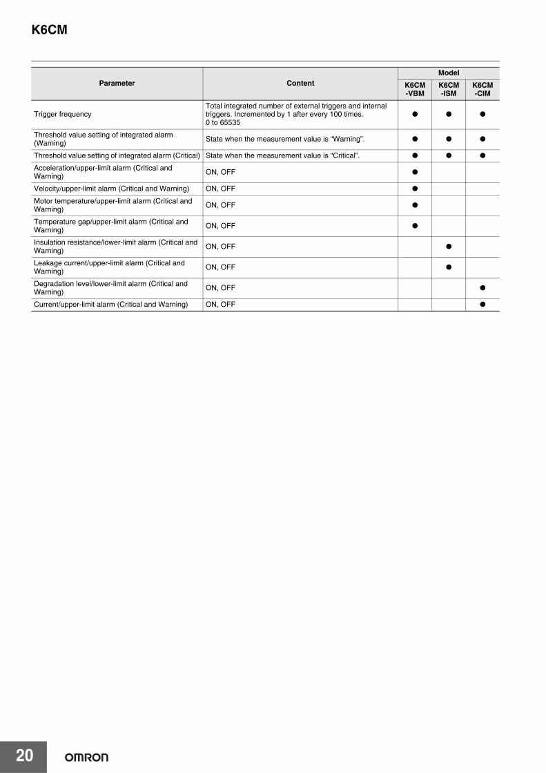
Trigger frequencyTotal integrated number of external triggers and internal triggers. Incremented by 1 after every 100 times.0 to 65535
● ● ●
Threshold value setting of integrated alarm (Warning) State when the measurement value is “Warning”. ● ● ●
Threshold value setting of integrated alarm (Critical) State when the measurement value is “Critical”. ● ● ●
Acceleration/upper-limit alarm (Critical and Warning) ON, OFF ●
Velocity/upper-limit alarm (Critical and Warning) ON, OFF ●
Motor temperature/upper-limit alarm (Critical and Warning) ON, OFF ●
Temperature gap/upper-limit alarm (Critical and Warning) ON, OFF ●
Insulation resistance/lower-limit alarm (Critical and Warning) ON, OFF ●
Leakage current/upper-limit alarm (Critical and Warning) ON, OFF ●
Degradation level/lower-limit alarm (Critical and Warning) ON, OFF ●
Current/upper-limit alarm (Critical and Warning) ON, OFF ●
Parameter ContentModel
K6CM-VBM
K6CM-ISM
K6CM-CIM

Terms and Conditions AgreementRead and understand this catalog.
Please read and understand this catalog before purchasing the products. Please consult your OMRON representative if you have any questions or comments.
Warranties.(a) Exclusive Warranty. Omron’s exclusive warranty is that the Products will be free from defects in materials and workmanship
for a period of twelve months from the date of sale by Omron (or such other period expressed in writing by Omron). Omron disclaims all other warranties, express or implied.
(b) Limitations. OMRON MAKES NO WARRANTY OR REPRESENTATION, EXPRESS OR IMPLIED, ABOUT NON-INFRINGEMENT, MERCHANTABILITY OR FITNESS FOR A PARTICULAR PURPOSE OF THE PRODUCTS. BUYER ACKNOWLEDGES THAT IT ALONE HAS DETERMINED THAT THE PRODUCTS WILL SUITABLY MEET THE REQUIREMENTS OF THEIR INTENDED USE.
Omron further disclaims all warranties and responsibility of any type for claims or expenses based on infringement by the Products or otherwise of any intellectual property right. (c) Buyer Remedy. Omron’s sole obligation hereunder shall be, at Omron’s election, to (i) replace (in the form originally shipped with Buyer responsible for labor charges for removal or replacement thereof) the non-complying Product, (ii) repair the non-complying Product, or (iii) repay or credit Buyer an amount equal to the purchase price of the non-complying Product; provided that in no event shall Omron be responsible for warranty, repair, indemnity or any other claims or expenses regarding the Products unless Omron’s analysis confirms that the Products were properly handled, stored, installed and maintained and not subject to contamination, abuse, misuse or inappropriate modification. Return of any Products by Buyer must be approved in writing by Omron before shipment. Omron Companies shall not be liable for the suitability or unsuitability or the results from the use of Products in combination with any electrical or electronic components, circuits, system assemblies or any other materials or substances or environments. Any advice, recommendations or information given orally or in writing, are not to be construed as an amendment or addition to the above warranty.
See http://www.omron.com/global/ or contact your Omron representative for published information.
Limitation on Liability; Etc.OMRON COMPANIES SHALL NOT BE LIABLE FOR SPECIAL, INDIRECT, INCIDENTAL, OR CONSEQUENTIAL DAMAGES, LOSS OF PROFITS OR PRODUCTION OR COMMERCIAL LOSS IN ANY WAY CONNECTED WITH THE PRODUCTS, WHETHER SUCH CLAIM IS BASED IN CONTRACT, WARRANTY, NEGLIGENCE OR STRICT LIABILITY.
Further, in no event shall liability of Omron Companies exceed the individual price of the Product on which liability is asserted.
Suitability of Use.Omron Companies shall not be responsible for conformity with any standards, codes or regulations which apply to the combination of the Product in the Buyer’s application or use of the Product. At Buyer’s request, Omron will provide applicable third party certification documents identifying ratings and limitations of use which apply to the Product. This information by itself is not sufficient for a complete determination of the suitability of the Product in combination with the end product, machine, system, or other application or use. Buyer shall be solely responsible for determining appropriateness of the particular Product with respect to Buyer’s application, product or system. Buyer shall take application responsibility in all cases.
NEVER USE THE PRODUCT FOR AN APPLICATION INVOLVING SERIOUS RISK TO LIFE OR PROPERTY OR IN LARGE QUANTITIES WITHOUT ENSURING THAT THE SYSTEM AS A WHOLE HAS BEEN DESIGNED TO ADDRESS THE RISKS, AND THAT THE OMRON PRODUCT(S) IS PROPERLY RATED AND INSTALLED FOR THE INTENDED USE WITHIN THE OVERALL EQUIPMENT OR SYSTEM.
Programmable Products.Omron Companies shall not be responsible for the user’s programming of a programmable Product, or any consequence thereof.
Performance Data.Data presented in Omron Company websites, catalogs and other materials is provided as a guide for the user in determining suitability and does not constitute a warranty. It may represent the result of Omron’s test conditions, and the user must correlate it to actual application requirements. Actual performance is subject to the Omron’s Warranty and Limitations of Liability.
Change in Specifications.Product specifications and accessories may be changed at any time based on improvements and other reasons. It is our practice to change part numbers when published ratings or features are changed, or when significant construction changes are made. However, some specifications of the Product may be changed without any notice. When in doubt, special part numbers may be assigned to fix or establish key specifications for your application. Please consult with your Omron’s representative at any time to confirm actual specifications of purchased Product.
Errors and Omissions.Information presented by Omron Companies has been checked and is believed to be accurate; however, no responsibility is assumed for clerical, typographical or proofreading errors or omissions.

Authorized Distributor:
In the interest of product improvement, specifications are subject to change without notice.
Cat. No. N218-E1-01 1117(1117)
© OMRON Corporation 2017 All Rights Reserved.
OMRON Corporation Industrial Automation Company
OMRON ELECTRONICS LLC2895 Greenspoint Parkway, Suite 200 Hoffman Estates, IL 60169 U.S.A.Tel: (1) 847-843-7900/Fax: (1) 847-843-7787
Regional HeadquartersOMRON EUROPE B.V.Wegalaan 67-69, 2132 JD HoofddorpThe NetherlandsTel: (31)2356-81-300/Fax: (31)2356-81-388
Contact: www.ia.omron.comKyoto, JAPAN
OMRON ASIA PACIFIC PTE. LTD.No. 438A Alexandra Road # 05-05/08 (Lobby 2), Alexandra Technopark, Singapore 119967Tel: (65) 6835-3011/Fax: (65) 6835-2711
OMRON (CHINA) CO., LTD.Room 2211, Bank of China Tower, 200 Yin Cheng Zhong Road, PuDong New Area, Shanghai, 200120, China CSM_1_1_1117Tel: (86) 21-5037-2222/Fax: (86) 21-5037-2200