
Motivation - IPFW · 10/16/2016 1 Fall 2013 Honore Hodary Motivation Overheating is one of the most...
21
10/16/2016 1 Fall 2013 Honore Hodary Motivation Overheating is one of the most common cause of failure in DC motors. It can lead to bearings failure (motor jam), winding‐isolation (short‐circuit), and degradation of the magnets. The amount of current drawn and the temperature generated by DC motor are crucial in understanding the performance and reliability of motors. Provide a low cost and effective tool for measuring the amount of current drawn and heat generated by DC motors.
Transcript of Motivation - IPFW · 10/16/2016 1 Fall 2013 Honore Hodary Motivation Overheating is one of the most...

10/16/2016
1
Fall 2013
Honore Hodary
Motivation Overheating is one of the most common cause of failure in DC motors. It can lead to bearings failure (motor jam), winding‐isolation (short‐circuit), and degradation of the magnets.
The amount of current drawn and the temperature generated by DC motor are crucial in understanding the performance and reliability of motors.
Provide a low cost and effective tool for measuring the amount of current drawn and heat generated by DC motors.

10/16/2016
2
Goals
Provide a cost effective mechanism for acquiring temperature and current data.
Allow the operator to determine when to perform preventive maintenance.
Record the temperature and current data to a host computer.
Display current and temperature data on LCD
Design a compact, portable, and user friendly system.
Functional Requirements
Measure the heat (temperature) generated by the motor.
Measure the amount of current drawn by the motor.
Record temperature and current data to a host computer for later analysis.
Display current and temperature data on LCD display.

10/16/2016
3
Specification Measured temperature shall be in the range of 0 to 300 degrees Fahrenheit.
Measured current shall be in the range of 1 to 15 A.
The temperature accuracy shall be within +‐2 degrees Fahrenheit.
The current accuracy shall be within +‐100 mA
Both temperature and current should be transmitted to a host computer every 60 seconds.
The operating temperature shall be between 0 and 100 degrees Fahrenheit.
The system shall not exceed 4 lbs.
System Block Diagram

10/16/2016
4
Subsystems Sensors module
Power supply module
Microcontroller module
Data display module
Data storage module
Signal conditioning module
Sensors Selection Criteria Transfer function must be linear
Response time must less than 100 ms
Must have great accuracy
Noise level must be less than 100 mV
Dynamic range must be between 0 A and 15 A
Must be easy to use

10/16/2016
5
TLS 15‐NP Current Sensor Type: Hall Effect
Maximum measure current: 15 A
Supply voltage: 5V
Supply current: 1.6 mA
Output type: voltage
Response time: <100 ns
Sensitivity: 41.6 mV/A
TLS 15‐NP

10/16/2016
6
CSLA2CD Current Sensor
Type: Hall Effect
Max Current: 72 A
Supply Current: 10 uA
Supply Voltage: 8V – 13.2V
Output type: Voltage
Response Time:3us
Sensitivity: 32.7 mV/A
CSLA2CD Sensor

10/16/2016
7
Sensors (Continued) Temperature Sensor (LM34)
Internally calibrated
Linear Output: 10mV/Degree Fahrenheit
Supply Voltage: 5V to 30V
Supply Current:75 uA
Response Time:750 mS
Measurement Range: ‐50 to 300 Degrees Fahrenheit
Accuracy: +‐2 Degrees
LM34 Sensor

10/16/2016
8
DS1820 Dynamic range: ‐67 to 257
Accuracy: 0.5 degrees Fahrenheit
Resolution: 10 bits
Cost: $6.00
DS1820
10/16/2016
9
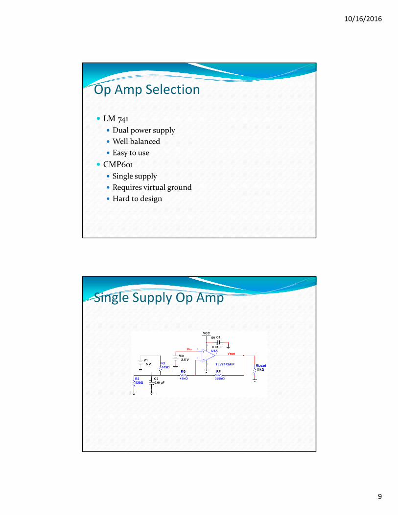
Op Amp Selection
LM 741
Dual power supply
Well balanced
Easy to use
CMP601
Single supply
Requires virtual ground
Hard to design
Single Supply Op Amp

10/16/2016
10
Signal Conditioning Module
Temperature Sensor Signal Conditioning Circuit
VCC
5V
U1
MCP601-I/P
3
2
4
7
6
RG
47kΩ
RF
329kΩ
C1
0.01µF
C20.01µFR2
820Ω
R1615Ω
VDD5 V
VinVout

10/16/2016
11
Current Sensor Signal Conditioning Circuit
U2
MCP601-I/P
3
2
4
7
6
R3
47kΩ
R4
329kΩ
C2
0.01µF
C30.01µF
R5820Ω
R6615Ω
VDD5 V
U4
MCP601-I/P
3
2
4
7
6
VCC
5V
VCC
5V
R11
137kΩ
R12
137kΩ
C6820pF
C8
1.64nF C9
0.01µF
U5
MCP601-I/P
3
2
4
7
6
C10
0.01µF
VCC
5V
Vin
Vout
Power SupplyWall adapter
Input: 110V – 125V
Output: 12V
Current: 1A
Regulator
Type: LM7805
Voltage: 5V
Current: 1A

10/16/2016
12
Power Supply Schematic
U1LM7805CTLINE VREG
COMMON
VOLTAGE
C1.01µF
C2.01µF
D11N4007G
OutputInput
USB Communication Module FT232R Controller
Provides communication channel between the MCU and the host computer.
Converts USB port to Virtual COM port in the host computer.
Manages enumeration and other USB bus communication requirements in hardware.
No USB specific firmware required.
Supports Bus‐powered and Self‐powered.
USB 2.0 full‐speed compatible.

10/16/2016
13
USB Controller (continued) Operating temperature: ‐40 to 85 degrees C.
Supply voltage: 1.8V to 5.25V.
Supply current: 15mA
Data transfer: 300 baud to 3 Mbaud.
USB Controller Schematic

10/16/2016
14
Microcontroller PIC18F4550
Analog‐to‐digital conversion (ADC)
Process temperature and current data.
Transfers temperature and current data to the host computer.
Display temperature and current data on LCD display.
Microcontroller Communication With USB Controller
Communication With DAC
Communication with LCD display

10/16/2016
15
Microcontroller (continued) Supply voltage: 2V to 5.5V
Supply current: 5.8 uA
Sink/source current: 25mA
Clock: Internal and external oscillator.
Timers: 4
ADC resolution: 10‐bit
Analog channels: 13
Interrupt sources: 20
Microcontroller Schematic

10/16/2016
16
System Integration
U3
UM232R
123456789101112 13
1415161718192021222324
U2
MCP601-I/P
3
2
4
7
6
R3
47kΩ
R4
329kΩ
C2
0.01µF
C30.01µF
R5820Ω
R6615Ω
U4
MCP601-I/P
3
2
4
7
6
R11
137kΩ
R12
137kΩ
C6820pF
C8
1.64nF C9
0.01µFU5
MCP601-I/P
3
2
4
7
6
C10
0.01µF
J3
PJ-102A
U7
GND
VCCCV
RSRW
E
D0D1D2D3D4D5D6D7
U8LM7805CTLINE VREG
COMMON
VOLTAGE
D1 1N4007G
C50.33µF
C70.1µF
D2
1N4007G
S1Key = Space
0
VCC
5V
VCC
VCC
VCC
VCC
U1LTSR 15_NP
1234 5 6
789
10
J1
HDR1X2
1
2
Isense_In
Isense_Out
VCC0
OUT
0 0
C1
0.01µF
U6
MCP601-I/P
3
2
4
7
6
R8
137kΩ
R9
137kΩ
C4820pF
C11
1.64nF C12
0.01µFU9
MCP601-I/P
3
2
4
7
6
R1
6kΩ R210kΩ
RG
6kΩ
RF
10kΩ
C13
0.01µFU10
MCP601-I/P
3
2
4
7
6
J2
HDR1X3
1
2
3
VCC
0
0
0VCC
0
0
VCC
0
U11
PIC18F4550
1234567891011121314151617181920 21
22232425262728293031323334353637383940
R7
10kΩ
C1422pF
C1522pF
VCC
VCC0
X1HC-49/U_11MHz
0
VCC0
AN0
AN0
AN1
AN1
VCC
0
RB3
RB3RB2
RB2
RB1
RB1
RB0
RB0
0
RB5
RB5
0RB4
RB4
0
VCC
0
00
VCC
0
0
0
00
0
0
0
0
Software Architecture

10/16/2016
17
Software: Microcontroller
Programming language: C
Program Initialization Configure ports
Configure ADC
Configure USART
ADC Conversion Reads data from analog channels
Format data
Data transfer/display Transfer data to the host computer
Display data on LCD display
Algorithm: Microcontroller

10/16/2016
18
Statechart
Testing and Validation

10/16/2016
19
Testing and Validation
Cost and Resource Management
Part Name Quantity Price Per Unit Total Cost
Actual Amount of Money Spent
MCP601 Op Amp 6 $0.60 $3.60 $3.60
TLS 15-NP Current Sensor
1 $17.00 $17.00 $17.00
LM34DZ Temperature sensor
1 $6.60 $6.66 $6.60
Resistors 17 $12.00(per kit) $12.00 $0.00 (Had it )
Capacitors 15 $9.00 (per kit) $9.00 $0.00 (Had it)
UM232R USB-to-UART Converter
1 $11.00 $11.00 $21.00
PIC18F4550 1 $6.90 $6.90 $0.00(Had it )
Terminal Blocks 2 $1.00 $2.00 $0.00 (removedfrom power supply)
Barrel power Jack 1 $3.00 $3.00 $0.00 (removed from an old router)
Diode 2 $6.00 (per kit) $12.00 $0.00 (purchased two years ago)
Oscillator 1 $4.00 $4.00 $0.00 (Had the part in my tool box)
Total $97.16 $48.20

10/16/2016
20
Risks
The microcontroller not sending data to PC
The temperature sensor not being attached to the motor
Lesson Learned
Project management
Planning is key to a successful project
Always buy extra components in case one get damaged
Gained valuable experience in analog signal conditioning
Gained experience programming PIC microcontroller
10/16/2016
21
Conclusion
All features of the USB Based Data Acquisition System were successfully implemented
The cost of designing the UBS Based Data Acquisition System was well bellow $100
Did not have enough time to focus on the project as given my work related responsibilities
Overall, this was a very rewarding experience
Thank you.
Questions?