Motional FeedBack loudspeaker system (MFB) - by-rutgers Feedback.pdf · Motional FeedBack...
7
Motional FeedBack loudspeaker system (MFB) Introduction A motional feedback system is a combination of a power amplifier and a loudspeaker in which (a part of) the feedback is obtained from the movement of the cone of an electro dynamic loudspeaker. In the picture at the left the difference is shown. On top you will find a normal power amplifier and speaker system. De- pending on the function β, which often is just an attenuator with a flat amplitude – frequency response, the amplification of the amp is determined. Moreover a very important function of negative feed back is the reduction of nonlinear distortion! In the picture below the so called motional feedback system has been displayed. The frequency response of the whole system is determined by β, the conversion of the input voltage to the piezo output and that of the correction. In all feedback (every time the word: ‘feedback’ is used, I mean: ‘negative feedback’. In Dutch: ‘tegenkoppeling’) systems one has to deal with stability problems. The larger the bandwidth of a system the more feedback could be applied (e.g. with a unity gain stable op amp the gain could be reduced to 1). We all know the stability problems with a tube power amplifier because of the limited bandwidth of the output transformer. They are that serious that many people prefer such amps without any feedback…. But why should you construct a motional feedback system? Well, it flattens the acoustic frequency response and reduces the distortion even in a (very) small enclosure set up! What could be expected? With an 8” loudspeaker in a 15 litre enclosure the frequency response could be flat from 30 Hz up to, say, 500 Hz. Moreover the distortion will be < 0.5 %. Mind that loudspeakers do have a distortion of 5 to 10 % primarily near the resonance frequency of the loudspeaker in its enclosure. The conversions A loudspeaker converts the current though its voice coil into sound pressure and/or air velocity by moving its cone. But how to get a transducer which converts the cone movements into an electric voltage for the feedback? Many solutions have been passed in review. See the literature. But to make a long story short, the sensor at the cone must be an acceleration detector. In the document: Bewegingstegenkoppeling bij luidsprekers’ (a document from the late sixties at Philips NatLab in the Netherlands [on this website]) this has been explained. From a voltage which is proportional to the acceleration, integration simply offers a velocity detector and two times integration offers a displacement detector. With acceleration feedback (with an acceleration detector or ‘accelerometer’) the acoustic frequency response could be obtained as flat. The resonance frequency of the speaker lowers but at the same time the Q of the system enhances! By also applying velocity feedback this Q will be managed. The accelerometer More than 40 years after the production of the first Philips Motional Feedback loudspeakers, the technique has been changed a lot. At the voice coil of the MFB loudspeaker a piezo element (see: ‘Pic- tures of some details’ on this site) had been fixed to produce the wanted electrical signal to serve the feedback. Nowadays such accelerometers are luckily introduced onto the market. Eventually, after three years of development, the piezo detector used in this project is the accelerometer ACH-01 from Measurement Specialties in the loudspeaker: RRS210HF-4 from Dayton Audio.
Transcript of Motional FeedBack loudspeaker system (MFB) - by-rutgers Feedback.pdf · Motional FeedBack...
Motional FeedBack loudspeaker system (MFB) Introduction
A motional feedback system is a combination of a power amplifier and a loudspeaker in which (a part of) the feedback is obtained from the movement of the cone of an electro dynamic loudspeaker. In the picture at the left the difference is shown. On top you
will find a normal power amplifier and speaker system. De-pending on the function β, which often is just an attenuator with a flat amplitude – frequency response, the amplification of the amp is determined. Moreover a very important function of negative feed back is the reduction of nonlinear distortion!
In the picture below the so called motional feedback system has been displayed. The frequency response of the whole system is determined by β, the conversion of the input voltage to the piezo output and that of the correction.
In all feedback (every time the word: ‘feedback’ is used, I mean: ‘negative feedback’. In Dutch: ‘tegenkoppeling’) systems one has to deal with stability problems. The larger the bandwidth of a system the more feedback could be applied (e.g. with a unity gain stable op amp the gain could be reduced to 1). We all know the stability problems with a tube
power amplifier because of the limited bandwidth of the output transformer. They are that serious that many people prefer such amps without any feedback….
But why should you construct a motional feedback system? Well, it flattens the acoustic frequency response and reduces the distortion even in a (very) small enclosure set up! What could be expected?
With an 8” loudspeaker in a 15 litre enclosure the frequency response could be flat from 30 Hz up to, say, 500 Hz. Moreover the distortion will be < 0.5 %. Mind that loudspeakers do have a distortion of 5 to 10 % primarily near the resonance frequency of the loudspeaker in its enclosure. The conversions
A loudspeaker converts the current though its voice coil into sound pressure and/or air velocity by moving its cone. But how to get a transducer which converts the cone movements into an electric voltage for the feedback? Many solutions have been passed in review. See the literature. But to make a long story short, the sensor at the cone must be an acceleration detector. In the document: Bewegingstegenkoppeling bij luidsprekers’ (a document from the late sixties at Philips NatLab in the Netherlands [on this website]) this has been explained. From a voltage which is proportional to the acceleration, integration simply offers a velocity detector and two times integration offers a displacement detector. With acceleration feedback (with an acceleration detector or ‘accelerometer’) the acoustic frequency response could be obtained as flat. The resonance frequency of the speaker lowers but at the same time the Q of the system enhances! By also applying velocity feedback this Q will be managed. The accelerometer
More than 40 years after the production of the first Philips Motional Feedback loudspeakers, the technique has been changed a lot. At the voice coil of the MFB loudspeaker a piezo element (see: ‘Pic-tures of some details’ on this site) had been fixed to produce the wanted electrical signal to serve the feedback. Nowadays such accelerometers are luckily introduced onto the market. Eventually, after three years of development, the piezo detector used in this project is the accelerometer ACH-01 from Measurement Specialties in the loudspeaker: RRS210HF-4 from Dayton Audio.
The project
has been executed with TentLabs in Eindhoven the Netherlands and could not have been finished without the elaborate help of Paul Vancluysen with the expensive tools Microsim and Leap and the advices of Rob Munnig Smidt of RMS Acoustics & Mechatronics. Paul has translated the signal transfer from the loudspeaker terminals to the accelerometer output for all different used speakers during the project and developed the circuits for the correction. It was my job to choose the types of loudspeaker and the piezo detectors, to modify the loudspeakers with these accelerometers, to execute the electric and acoustic measurements and control the progress of the project. During the last three years we went through many speakers and detectors before the eventually choice could be made! Mechanical problems
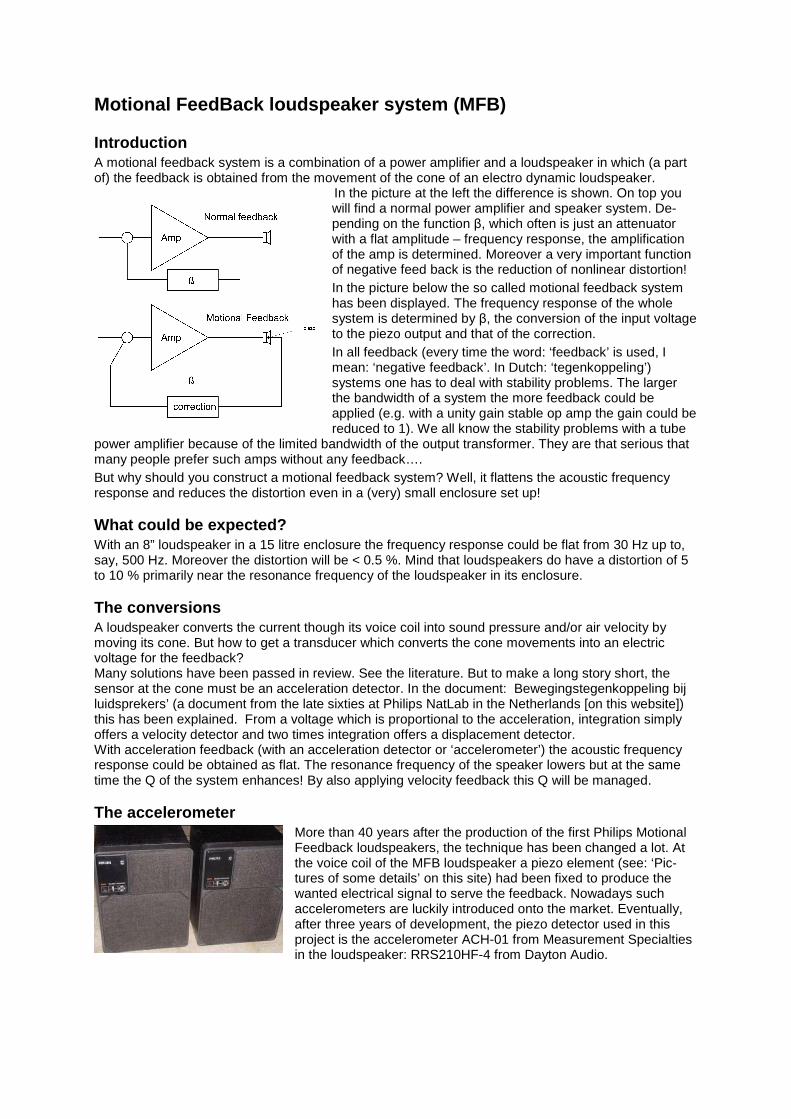
To lift a little corner of the veil: the mechanical connection between the voice coil of the speaker and the accelerometer should be as rigid as possible to avoid resonances at higher frequencies. The ACH-01 accelerometer has been mounted on a 50 mm round, 5 mm thick glass reinforced polyester plate which in turn is fixed on a piece of 50 mm plastic drain pipe before it should be let down into the 50 millimetre voice coil. All parts are fixed with super glue.
On the green PCB resides the SMD J310 FET with two SMD resistors (see the diagram). The correction circuit
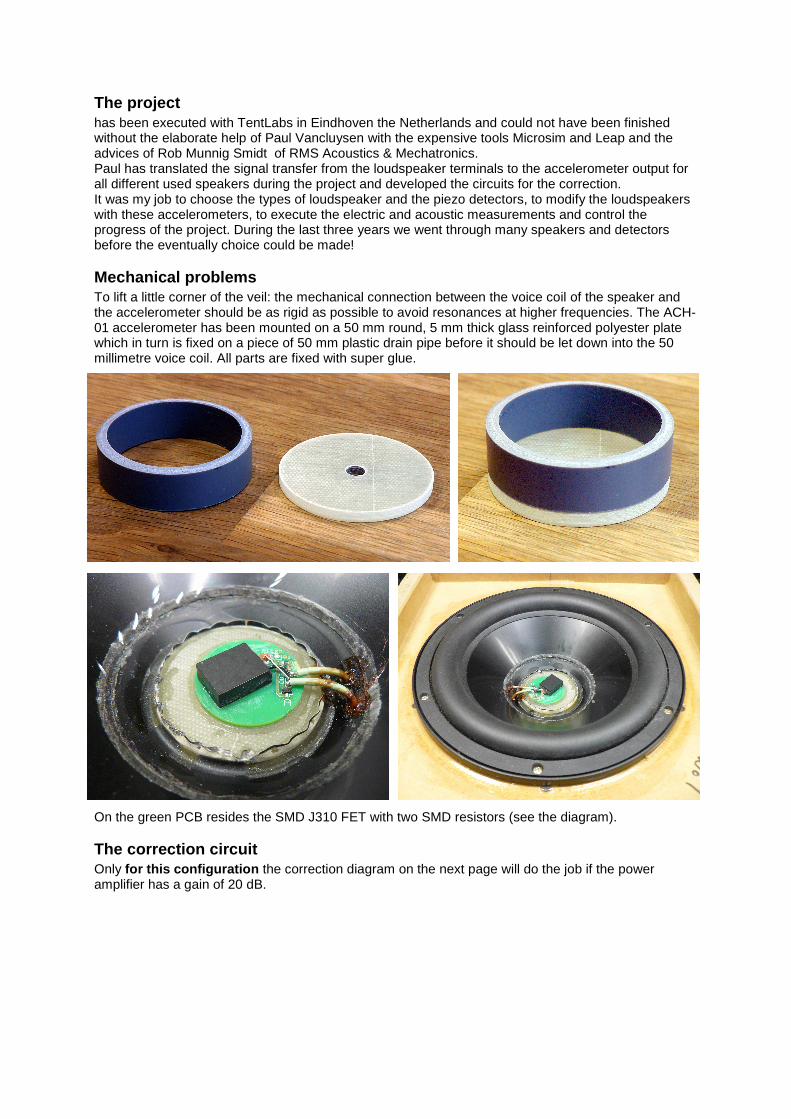
Only for this configuration the correction diagram on the next page will do the job if the power amplifier has a gain of 20 dB.

The band pass filter
Because of the limited bandwidth of the MFB system, a band pass filter at the input is needed. In our case from 40 to 500 Hz has been chosen otherwise the cone excursion at very low frequencies will exceed the linear region of the rather small 8” loudspeaker too soon and many subjects in the listening room will patter. Within this filter also the linear baffle step distortion could be corrected.
This filter (without baffle step correction!) has a frequency response as below:
The filter should be connected to the correction circuit between R23 and ground after discon-nection of R23 from ground of course.
The PCB
To give an idea of the PCB on which the band pass filter and the correction circuit has been designed, see the next page. The small PCB at the right serves the reduction of the ±50 volt for the PA to ±12 V for the op amps in the band pass filter and the correction circuit.

To get an idea of the placement of the components:
Measurements
During measurements of the overall system the loop is closed as with the simulations. This means that the accelerometer has been connected to the correction (via via!) which circuit is built close to the PA and connected to it. The PA has been connected to the loudspeaker (mind the phase!). R23 has been connected to ground. In the correction diagram the measuring points x, y and Z have been implemented so we can measure x=f(freq) and y=f(freq) with Z as input. Then we get:

The red curve is y/Z and the black one is x/Z. This shows that the negative feedback of this MFB works from less than 20 Hz up to about 500 Hz. The feedback is 17 dB at 65 Hz, which is the resonance frequency of the speaker in the small enclosure (with damping material). Here the distortion is largest which will be reduced nearly 10 x.
Two speakers?
If the acoustic power of one speaker does not satisfy, this could be solved by simply connect a second speaker in parallel. This means a second speaker of the same type in the same enclosure with the same amount of damping material. They should not be put in one box of two times the volume of the single speaker because at very low frequencies the acoustic coupling will be stronger than the electric coupling between the two cones. Put them in series connection is impossible, so the impedance offered to the amp will be halved, 2 Ω in our case. It is even possible to connect a large number of equal speakers to one MFB-speaker via several PA’s! A box for two speakers could look like:
so that a unit for middle and high frequencies could be placed on top of it. Such a unit could be an electrostatic loudspeaker (ESL), as shown in ‘Pictures of the ESL/MFB-prototype’ or in ‘(Gebogen) Luidspreker Array als Quasi Dipool’ on this site. Read also ‘ESL + MFB is the best of 2 worlds’.

Used Power Amplifier
In case a class-D amp (with a switch mode power supply) would satisfy very well for this application. Look for Hypex! Subwoofer
MFB is very suitable in subwoofer systems of course. With TentLabs such a configuration is in preparation. The amp has been completed with a number of dials with which the wanted frequency response, phase and amplitude will be adjustable. Keep an eye on: http://www.tentlabs.com/index.html Conclusions
MFB is a complicated system which offers a clear undistorted bass. This best could be demonstrated with a cello or pianoforte (Steinway). You get a beautiful semitone pitch perception at the lower notes. But: it is hard to construct and to reproduce. This description above is absolutely insufficient for DIY-ers if they are not familiar with the subject. They better could by a second hand Philips system for upgrading (see www.mfbfreaks.com ). 11-3-2014