Mosquito Bite Prevention through Graphene Barrier Layers · 2019-08-21 · 1 Mosquito Bite...
26
1 Mosquito Bite Prevention through Graphene Barrier Layers Cintia J. Castilho, Dong Li, Muchun Liu, Yue Liu, Huajian Gao*, Robert H. Hurt* Section 1: Additional information on the characterization of graphene materials ▪ Fig. S1: Morphology characterization of the graphene nanosheets and graphene films ▪ Fig. S2: Hexane permeation tests on graphene films Section 2: Additional information on the live mosquito experiments ▪ Fig. S3: Details of the experimental apparatus ▪ Fig. S4: Additional example images from live mosquito experiments ▪ Fig. S5: Biting statistics using the Poisson model applied to bite numbers as integer count data ▪ Fig. S6: Effect of water or sweat addition on mosquito behavior ▪ Fig. S7: Mosquito behavior during experiments with parafilm coatings on skin. Section 3: Additional information on the mechanical penetration tests ▪ Fig. S8: Details of the mechanical penetration test apparatus ▪ Note 1: Description of nanoindentation experiments using atomic force microscopy Section 4: Additional information on the mechanical modelling ▪ Fig. S9: Mechanical responses of an indented free-standing membrane ▪ Fig. S10: Effects of a hyperelastic substrate on the penetration force of a thin membrane ▪ Fig. S11: Effect of Poisson’s ratio on mechanical responses of a free-standing membrane under indentation ▪ Fig. S12: Scaling laws in the indentation force profile from the needle penetration experiment ▪ Table 1: Dimensional and dimensionless quantities in the membrane penetration model ▪ Table 2: Values of coefficient series in mechanical modelling for different Poisson’s ratios ▪ Table 3: Parameters in the needle penetration tests and membrane indentation model Section 5: Additional characterization of graphene films in the dry and wet states ▪ Fig. S13: X-Ray Diffraction Pattern of graphene films at dry and wet state ▪ Fig. S14: Thermogravimetric analysis (TGA) of graphene films at dry and wet state www.pnas.org/cgi/doi/10.1073/pnas.1906612116
Transcript of Mosquito Bite Prevention through Graphene Barrier Layers · 2019-08-21 · 1 Mosquito Bite...

1
Mosquito Bite Prevention through Graphene Barrier Layers
Cintia J. Castilho, Dong Li, Muchun Liu, Yue Liu, Huajian Gao*, Robert H. Hurt*
Section 1: Additional information on the characterization of graphene materials
▪ Fig. S1: Morphology characterization of the graphene nanosheets and graphene films
▪ Fig. S2: Hexane permeation tests on graphene films
Section 2: Additional information on the live mosquito experiments
▪ Fig. S3: Details of the experimental apparatus
▪ Fig. S4: Additional example images from live mosquito experiments
▪ Fig. S5: Biting statistics using the Poisson model applied to bite numbers as integer count
data
▪ Fig. S6: Effect of water or sweat addition on mosquito behavior
▪ Fig. S7: Mosquito behavior during experiments with parafilm coatings on skin.
Section 3: Additional information on the mechanical penetration tests
▪ Fig. S8: Details of the mechanical penetration test apparatus
▪ Note 1: Description of nanoindentation experiments using atomic force microscopy
Section 4: Additional information on the mechanical modelling
▪ Fig. S9: Mechanical responses of an indented free-standing membrane
▪ Fig. S10: Effects of a hyperelastic substrate on the penetration force of a thin membrane
▪ Fig. S11: Effect of Poisson’s ratio on mechanical responses of a free-standing membrane
under indentation
▪ Fig. S12: Scaling laws in the indentation force profile from the needle penetration
experiment
▪ Table 1: Dimensional and dimensionless quantities in the membrane penetration model
▪ Table 2: Values of coefficient series in mechanical modelling for different Poisson’s ratios
▪ Table 3: Parameters in the needle penetration tests and membrane indentation model
Section 5: Additional characterization of graphene films in the dry and wet states
▪ Fig. S13: X-Ray Diffraction Pattern of graphene films at dry and wet state
▪ Fig. S14: Thermogravimetric analysis (TGA) of graphene films at dry and wet state
www.pnas.org/cgi/doi/10.1073/pnas.1906612116

2
Section 1: Characterization of graphene materials.
Supplementary Figure S1. Graphene material characterization. a, AFM image and height profile of
as-produced GO nanosheets. The nanosheets show lateral size of ∼1 μm and thickness of ~1 nm. b, SEM images of GO nanosheets. Scale bar, 1 μm. c, X-ray diffraction patterns of the graphene films used in the
live mosquito experiments and puncture tests. The calculated interlayer spacing for rGO films is 0.37 nm
and for GO films is 0.84 nm.

3
Supplementary Figure S2. Custom-built diffusion cell used for graphene film permeation testing.
Top: custom diffusion cell used to test the permeation of vapor molecules through graphene films.
Bottom: Details of the graphene film support and system sealing. The device consists of an inner vessel
containing the liquid used in the test. The inner vessel is capped with an opened glass cover and a copper plate with a 1 cm hole for the GO films placed in between the vessel and the cover. O-rings are used to
further seal the system. An outer vessel creates the simulated atmosphere and is placed in a thermostatic
bath to control the temperature during the experiment. The outer vessel is mechanically stirred using a fan while the inner vessel is mechanically stirred using a magnetic stir bar (stir plate is shown in black under
the vessels in the figure), ensuring the transport resistances are minimized and only the film resistance is
measured. The simulated atmosphere in the outer vessel is created by passing dry air through a column of water. The liquid permeation was measured gravimetrically. The graphene film is supported by a copper
plate, and the film is fixed on the plate using an adhesive. A layer of aluminum foil is then used to further
seal the system. Liquid hexane is known to be rejected by dry graphene films (1) and thus was used to test
the films used in experiments. No mass loss was detected after 6 hours at T = 20°C, confirming the lack of cracks, holes and other defects in the graphene films as well as the quality of the seals in the device.

4
Section 2: Live mosquito experiments and experimental results
Supplementary Figure S3. Live mosquito experimental apparatus. a) Mosquito enclosure designed from a modified Plexiglas glovebox (see dimensions) placed within a biosafety cabinet. b) Labeled internal
contents of the enclosure. The inside temperature was regulated at 27°C ± 2°C by a heat lamp and controller.
Humidity was regulated at 75% ± 5% by using a humidifier and controller as described in Imam, et al [2014] (2). The red circles show the humidity and temperature sensors. The original gloves were removed,
and the holes converted to access ports for insertion of human arms without release of live mosquitoes. The
access ports were outfitted with a cheesecloth cover with a central insertion hole that can be kept closed
with a clamp between experiments.

5
Supplementary Figure S4. Additional example images from live mosquito experiments on human
skin patches with graphene coverings. a) Large group of attracted mosquitoes when rGO/cheesecloth
films were wetted with human sweat. b) Typical Aedes behavior on skin control experiments (no graphene) with cheesecloth overlayer. c) Images of single mosquitoes standing directly on graphene films: (left) on
wet rGO films near a sessile water droplet; (right): on wet GO hydrogel films.
6
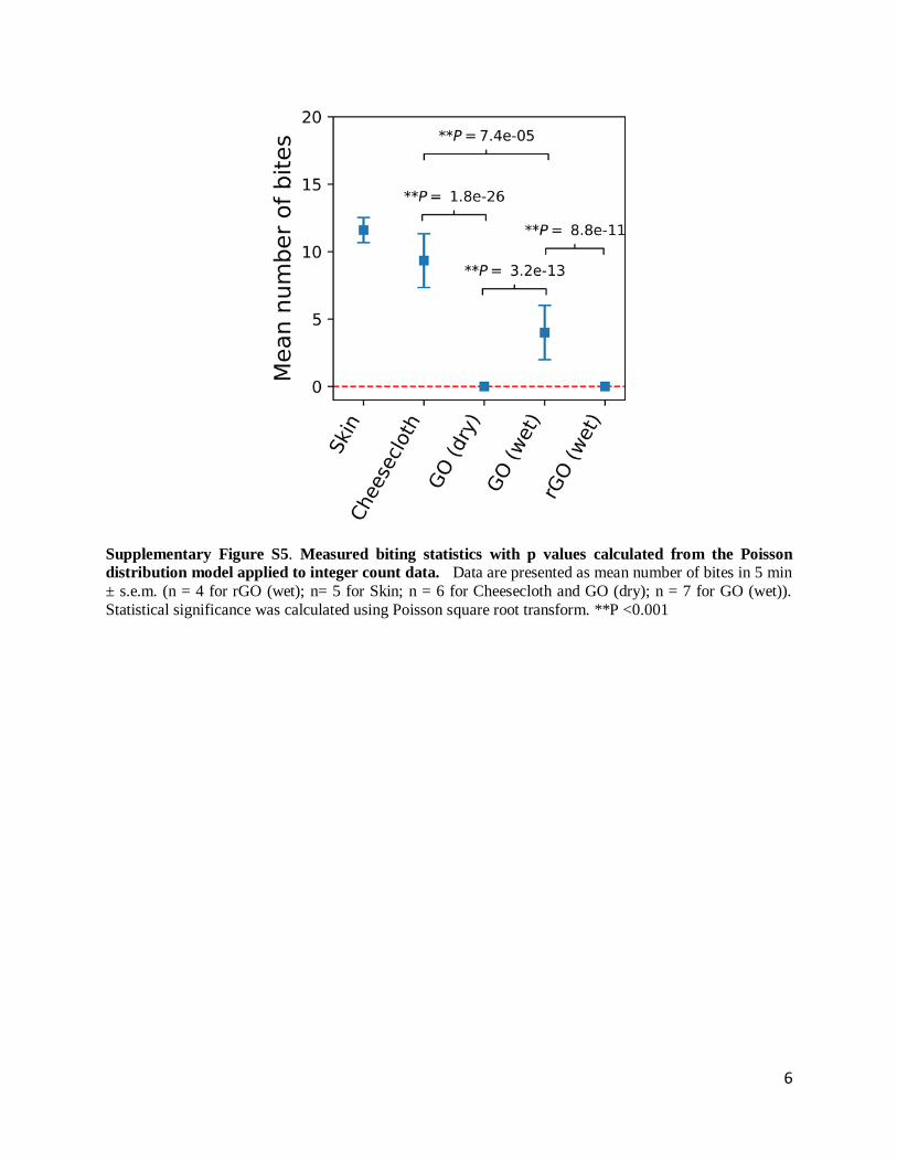
Supplementary Figure S5. Measured biting statistics with p values calculated from the Poisson
distribution model applied to integer count data. Data are presented as mean number of bites in 5 min
± s.e.m. (n = 4 for rGO (wet); n= 5 for Skin; n = 6 for Cheesecloth and GO (dry); n = 7 for GO (wet)).
Statistical significance was calculated using Poisson square root transform. **P <0.001

7
Supplementary Figure S6. Effect of water or sweat addition on mosquito behavior on graphene-
covered human skin patches. a, Mean residence times after initial contact on graphene films and control surfaces. b, Mean contact frequency of mosquitoes on graphene covered human skin patches and controls.
Supplementary Figure S7. Mosquito biting behavior on parafilm. a, Typical Aedes Aegypti behavior
observed during experiments with parafilm. Red arrows show swollen and red abdomen, reflecting successful blood feeding. Thinly stretched parafilm is commonly used in mosquito membrane feeders (3,
4). In those feeders, mosquitoes bite through parafilm to feed on underlying blood. b, Quantified mosquito
behavior during parafilm experiments. Left axis: Box plot of area-normalized bite frequency on parafilm. Right axis: Box plot of mosquito contact frequency (landings plus walk-ons) on parafilm.

8
Section 3: Mechanical penetration tests.
Supplementary Figure S8. Mechanical puncture test experiments. a, Sketch of the needle penetration
apparatus. The graphene films are clamped between two plexiglass supports with holes of 0.5 cm of
diameter. The inset shows an example of the raw data in the form of a force-displacement profile, from which the maximum load is reported as the critical penetration force. b, SEM images of the syringe needle
tip (stainless steel, 21 gauge) used in the tests (tip radius of curvature ~ 9µm).

9
Supplementary Note 1: Description of nanoindentation tests on graphene films using Atomic
Force Microscopy (AFM).
Free-standing graphene films were prepared as described in methods. The nanoindentation
samples were prepared by clamping free standing graphene films (thickness of 0.25 µm – 1 µm)
between two thin copper sheets supports. Two different types of AFM tips were used in the
nanoindentation tests: a Silicon tip (Asylum research probes) of radius 7 nm and spring constant
of 26 N/m and a diamond coated Silicon tip (Nanosensors) of radius 100 nm and spring constant
of 6 N/m. The tests were performed in contact mode. The forces exerted by the tips on the films
varied from ~0.5 µN to ~5 µN. The films were inspected using the AFM imaging and scanning
electron microscopy. No signs of indentation or puncture were found.

10
Section 4: Mechanical modelling
4.1 Membrane penetration model: the free-standing case
To help understand the mechanical behaviors of GO/rGO paper in the needle penetration
experiment, we adopted a theoretical model in which a circular membrane is pressed by a spherical
indenter tip at the center (Fig. 4b). The membrane is assumed to be linearly elastic until failure
occurs as the maximum tensile stress in the membrane reaches a critical value.
In the membrane penetration model, the following simplifications were made to reduce the
complexity of the problem without losing essential features: (1) In modeling the GO/rGO films as
a thin membrane, we neglect the effect of bending which is negligible compared to membrane
tension (5, 6); (2) The membrane boundary was assumed to be perfectly clamped, which is
expected to provide a lower bound to penetration force in case some boundary sliding occurs; (3)
The mosquito fascicle and the needle used in experiment (Supplementary Fig. S8) are modeled as
having spherical tips, an assumption commonly adopted in contact mechanics of membranes (7-
9); (4) The indenter tip was assumed to be rigid as the deformation of the tip is usually negligible
compared to that of a flexible membrane.
Even though the size of the indenter tip is much smaller than the membrane radius, it cannot be
neglected due to its significant influence on the membrane stress and penetration force. Assuming
that the indenter tip has the radius 𝑟𝑡, the membrane can be divided into two regions: the contact
region 0 ≤ 𝑟 ≤ 𝑟𝑐 where 𝑟𝑐 is the contact radius, and the free region 𝑟𝑐 < 𝑟 ≤ 𝑎 (Fig. 4b). The
contact region is loaded by pressure 𝑝(𝑟) from the indenter tip, and the outer edge of the free
region is clamped.

11
Supplementary Table 1. Dimensional and dimensionless quantities in the membrane penetration model
Dimensional variables Dimensionless variables
Radial coordinate 𝑟 𝜌 = 𝑟/𝑎
Radius of indenter tip 𝑟𝑡 𝜌𝑡 = 𝑟𝑡/𝑎
Radius of contract area 𝑟𝑐 𝜌𝑐 = 𝑟𝑐/𝑎
Membrane thickness ℎ 𝐻 = ℎ/𝑎
Axial deflection 𝑤 𝑊 = 𝑤/𝑎
Radial displacement 𝑢 𝑈 = 𝑢/𝑎
Stress components 𝜎𝑟, 𝜎𝜃 𝑆𝑟 = 𝜎𝑟/𝐸, 𝑆𝜃 = 𝜎𝜃/𝐸
Indentation/Penetration force 𝐹, 𝐹𝑝 𝐹 = 𝐹/(𝐸𝑎2), 𝐹𝑝 = 𝐹𝑝/(𝐸𝑎2)
Pressure in contact area 𝑃 𝑃 = 𝑝/𝐸
Föppl-Hencky membrane theory (10, 11) is adopted to model the indented membrane. With the
introduction of dimensionless variables listed in Supplementary Table 1, the out-of-plane/axial
equilibrium equation and compatibility equation can be expressed as (7-9):
−𝐻𝑆𝑟(𝜌)d𝑊(𝜌)
d𝜌=1
𝜌∫ 𝑃(𝜌)𝜌d𝜌𝜌
0
, (1)
𝜌𝜕
𝜕𝜌{1
𝜌
𝜕
𝜕𝜌[𝜌2𝑆𝑟(𝜌)]} +
1
2[d𝑊(𝜌)
d𝜌]
2
= 0. (2)
The normalized circumferential stress component 𝑆𝜃 can be obtained through the in-plane/radial
equilibrium equation:
𝑆𝜃(𝜌) =d
d𝜌[𝜌𝑆𝑟(𝜌)]. (3)
The normalized radial displacement 𝑈 can be calculated as
𝑈(𝜌) = 𝜌𝜀𝜃(𝜌) = 𝜌[𝑆𝜃(𝜌) − 𝜈𝑆𝑟(𝜌)] (4)
where 𝜀𝜃 is the circumferential strain component and 𝜈 is Poisson’s ratio of the membrane.
In the contact region 0 ≤ 𝜌 ≤ 𝜌𝑐 , the normalized membrane deflection 𝑊 has the following
profile:

12
𝑊(𝜌) = 𝑑̅ + √𝜌𝑡2 − 𝜌2 (5)
where 𝑑̅ is the normalized downward displacement of the indenter tip. Substituting Eq. (5) into
Eq. (2) and integrating the resulting equation twice yield
𝑆𝑟(𝜌) = −𝜌𝑡2 − 𝜌2
8𝜌2ln(𝜌𝑡
2 − 𝜌2) +4𝑐1 − 1
8+𝑐2𝜌2 (6)
where 𝑐1 and 𝑐2 are constants. Since the radial stress component is finite at the center of the
membrane, we have condition 𝑆𝑟(0) < ∞, which leads to
𝑐2 =𝜌𝑡2 ln 𝜌𝑡4
. (7)
In the free region 𝜌𝑐 < 𝜌 ≤ 1, the axial equilibrium equation (1) can be expressed as
−𝐻𝑆𝑟(𝜌)d𝑊(𝜌)
d𝜌=
�̅�
2𝜋𝜌 (8)
where the normalized penetration force �̅� = ∫ 𝑃(𝜌) ⋅ 2𝜋𝜌d𝜌𝜌𝑐
0. Combining Eq. (8) and Eq. (2)
yields
𝑆𝑟2(𝜌)𝜌3
𝜕
𝜕𝜌{1
𝜌
𝜕
𝜕𝜌[𝜌2𝑆𝑟(𝜌)]} = −
1
8(�̅�
𝜋𝐻)
2
. (9)
The solution to Eqs. (8) and (9) can be written in the form of polynomial series as
𝑊(𝜌) = 𝑄13 ∑𝑎𝑛 (1 − 𝜌
4𝑛+23 )
∞
𝑛=0
, (10a)
𝑆𝑟(𝜌) =3
2𝑄23 ∑𝑏𝑛𝜌
4𝑛−23
∞
𝑛=0
(10b)

13
where 𝑄 = �̅�/(2𝜋𝐻) is a dimensionless loading variable. {𝑎𝑛} and {𝑏𝑛} are coefficients whose
values can be determined through Eqs. (8) and (9) together with the boundary condition at the
outer edge of the membrane. For the clamped boundary,
𝑈(1) = [(1 − 𝜈)𝜌𝑆𝑟(𝜌) + 𝜌2𝜕𝑆𝑟(𝜌)
𝜕𝜌]𝜌=1
= 0, (11)
and the corresponding values of the first few entries in {𝑎𝑛} and {𝑏𝑛} are listed in Supplementary
Table 2.
Supplementary Table 2. Values of coefficient series {𝑎𝑛} and {𝑏𝑛} for different Poisson’s ratios
𝜈 = 0.17 𝜈 = 0.30
𝑎0 1.817 𝑏0 5.50× 10⁻¹ 𝑎0 1.817 𝑏0 5.50× 10⁻¹
𝑎1 6.05× 10⁻² 𝑏1 −5.50× 10⁻² 𝑎1 1.45× 10⁻² 𝑏1 −1.31× 10⁻²
𝑎2 5.18× 10⁻³ 𝑏2 −2.35× 10⁻³ 𝑎2 2.96× 10⁻⁴ 𝑏2 −1.35× 10⁻⁴
𝑎3 5.75× 10⁻⁴ 𝑏3 −2.00× 10⁻⁴ 𝑎3 7.87× 10⁻⁶ 𝑏3 −2.74× 10⁻⁶
𝑎4 7.21× 10⁻⁵ 𝑏4 −2.14× 10⁻⁵ 𝑎4 2.36× 10⁻⁷ 𝑏4 −7.00× 10⁻⁸
At the boundary between the contact and free regions, three continuity conditions should be
satisfied:
[d𝑊
d𝜌]𝜌=𝜌𝑐
−
= [d𝑊
d𝜌]𝜌=𝜌𝑐
+
, (12a)
[𝑊]𝜌=𝜌𝑐− = [𝑊]𝜌=𝜌𝑐
+ , (12b)
[𝑆𝑟]𝜌=𝜌𝑐− = [𝑆𝑟]𝜌=𝜌𝑐
+ (12c)
where (−) and (+) represent quantities on the sides of the contact and free regions, respectively.
The conditions (12a-c) are used to determine the values of the normalized contact radius 𝜌𝑐 ,
constants 𝑑̅ in Eq. (5) and 𝑐1 in Eq. (6). Once this is done, the displacement and stress fields in the
contact and free regions can be calculated from Eqs. (3-7) and (10).

14
In the present membrane indentation problem, it turns out that the radial stress component
monotonically decreases from the center to the edge of the membrane. Eq. (3) indicates that 𝑆𝜃 is
smaller than 𝑆𝑟 everywhere except at the center where we have 𝑆𝑟 = 𝑆𝜃 . Therefore, the maximum
tensile stress in the membrane corresponds to the radial stress at the center. According to the
maximum tensile stress criterion, we have
𝑆𝑟(0) ≤ 𝑆𝑡 (13)
where 𝑆𝑡 = 𝜎𝑡/𝐸 is the normalized tensile strength of the membrane. The corresponding
indentation force is taken as the critical penetration force of the membrane.
It can be verified that the above solution to membrane indentation problem converges to classical
Schwerin’s solution (5) to the indentation of a free-standing membrane under a point load.
Supplementary Fig. S9a compares Schwerin’s solution, finite element (FE) results and our
analytical solution. Relevant FE setups can be found in Section 4.2. Note that FE simulations have
convergence problems as the tip radius becomes very small. In Supplementary Fig. S9b, the
indentation forces predicted by the analytical solution are in good agreement with the FE results.
There is some difference in radial stress in the large deformation regime due to the intrinsic
limitations of Föppl-Hencky membrane theory.

15
Supplementary Figure S9. Mechanical responses of an indented free-standing membrane. (a) Convergence of solutions on membrane deformation as the tip radius goes to zero. (b) The profiles of
indentation force and central radial stress obtained from the analytical model and FE simulations.
Note that, in the analytical solution, Eqs. (12a-c) do not ensure smoothness in the radial stress and
continuity in the radial displacement at the edge of the contact area. The reason is that the
polynomial series in Eq. (10) is only an approximate solution to the governing equations.
Nevertheless, the present analytical solution should be applicable for the problem in hand since
the radial displacement is expected to be very small.
4.2 Effect of substrate
Finite element analysis was performed to investigate the effect of a hyperelastic substrate, which
mimics human skin, on the membrane penetration force 𝐹𝑝 . An axisymmetric FE model was
implemented in ABAQUS (Supplementary Fig. S10a). The bottom of the substrate was fixed,
while the lateral boundaries of the substrate and edges of the membrane were kept free. A spherical
indenter tip penetrated downward at the center of the membrane. Hard contact in the normal
0.03 0.06 0.09 0.12
0.210-6
0.410-6
0.610-6
0.810-6
Indentation force (FE results)
Indentation force (Present work)
Radial stress (FE results)
Radial stress (Present work)
Central deflection w0/a
Indenta
tion forc
e F
/(E
a2)
0.1
0.2
0.3
00
Radia
l str
ess
r/E
10-7
10-6
10-5
10-4
10-3
10-2
0.086
0.088
0.090
0.092
Centr
al deflection w
0/a
Tip radius rt/a
Schwerin's solution
FE results
Present work
a b

16
direction and frictionless interaction in the tangential direction were applied to the interfaces
between the tip and the membrane as well as between the membrane and the substrate.
A membrane element with zero bending stiffness was used to model the thin membrane, and the
indenter tip was treated as a rigid object. Other model parameters were taken from the needle
penetration experiment for dry GO/rGO paper (Supplementary Table 3). The substrate was
assumed to obey the following Neo-Hookean constitutive law for an incompressible hyperelastic
material:
𝑈 = 𝐶10(𝐼1̅ − 3) (14)
where 𝑈 is the strain energy per unit volume in the reference configuration, 𝐶10 is a coefficient
associated with the stiffness of the substrate, and 𝐼1̅ = �̅�12 + �̅�2
2 + �̅�32 is the first invariant of the
deviatoric strain tensor where �̅�𝑖 , 𝑖 = 1,2,3 are deviatoric principal stretches in the substrate. The
stiffness coefficient of stratum corneum of human skin 𝐶10 = 13.8 MPa (12) was used in this
study. The free-standing membrane model serves as a reference.
Supplementary Table 3. Parameters in the needle penetration tests and membrane indentation model.
Young’s modulus
(GPa) Poisson’s ratio
Membrane
thickness (µm)
Membrane radius
(mm)
Tip radius
(µm)
GO paper 2.28* 0.17† 0.5–5.0 2.5 9.0
rGO paper 2.55* 0.17† 0.5–5.0 2.5 9.0
* Obtained by fitting experimental data † Values reported in literature(13)

17
Supplementary Figure S10. Effects of a hyperelastic substrate on the penetration force of a thin
membrane. (a) The FE model of the tip-membrane-substrate system (b) Indentation force profiles for
different substrate stiffness coefficients. The cases 𝐶10 = 0 and 𝐶10/𝐸 = 0.006, where 𝐸 is the Young’s
modulus of the membrane, correspond to the cases without and with substrate support mimicking human
skin, respectively. Artificial stiffness coefficients are used in other cases. (c) Penetration forces for different
substrate stiffness coefficients. The inset shows details of the main figure when 𝐶10 is small. The membrane
thickness is assumed to be ℎ/𝑎 = 0.002, where 𝑎 is the membrane radius, in all cases in (b) and (c). (d)
Variations of penetration force with truncations on the membrane size.
Supplementary Fig. S10b shows the comparison between the free-standing membrane case and
supported membrane cases with the membrane tensile strength taken to be 𝜎𝑡/𝐸 = 0.05 .
Compared to the case of a free-standing membrane, the substrate is found to reduce the central
membrane deflection to 1/16 or less in all supported membrane cases. The corresponding
penetration forces are plotted in Supplementary Fig. S10c. The freestanding membrane case has
the lowest penetration force, implying that the membrane without support of substrate is the most
vulnerable to penetration by a sharp tip. The penetration force for supported cases decreases
approximately linearly with the stiffness coefficient 𝐶10 of the substrate, and the point representing
the free-standing case also lies close to the line. In particular, the penetration resistance of the thin
a
Membrane
Substrate
Tip
0.00 0.02 0.04 0.06 0.08 0.100.0
1.0x10⁻⁶
2.0x10⁻⁶
3.0x10⁻⁶
0.000 0.003 0.006
2x10⁻⁷
3x10⁻⁷
4x10⁻⁷
Supported cases
Freestanding case
Pe
netr
atio
n f
orc
e F
p/(
Ea
2)
Stiffness coefficient C10
/E
C10
= 13.8 MPa
c
0 1 22
4
6
8
10
12
Pen
etr
atio
n f
orc
e
Fp (
mN
)
Membrane radius a (mm)
C10
/E = 0 (freestanding)
C10
/E = 0.001
C10
/E = 0.006 (skin)
C10
/E = 0.020
d
0.00 0.01 0.02 0.03 0.04 0.05
10-8
10-7
10-6
Inde
nta
tio
n fo
rce
F/(
Ea
2)
Central deflection w0/a
C10
/E = 0 (freestanding)
C10
/E = 0.001
C10
/E = 0.006 (skin)
C10
/E = 0.020
C10
/E = 0.050
C10
/E = 0.100
b

18
membrane on human skin is almost twice that in the free-standing case. Supplementary Fig. S10d
confirms that the predicted penetration force is not sensitive to the selected membrane radius in
the model as along as the membrane radius is sufficiently large.
4.3 Effect of Poisson’s ratio
In our FE simulations and theoretical analysis, we have taken the Poisson’s ratio of GO/rGO paper
to be 𝜈 = 0.17 (13). It can be shown that the detailed choice of 𝜈 will not significantly affect our
conclusions.
Different Poisson’s ratios are considered in both FE and theoretical models of the free-standing
membrane case (Supplementary Fig. S11). The relationships between indentation force and central
deflection are shown under the membrane tensile strength of 𝑆𝑡 = 0.19 in Supplementary Fig.
S11a. It can be seen that the differences in central deflection between Poisson’s ratios 𝜈 = 0.1 and
𝜈 = 0.4 are less than 10% in both FE and theoretical results.

19
Supplementary Figure S11. Effect of Poisson’s ratio on mechanical responses of a free-standing
membrane under indentation. (a) Indentation force profiles for different Poisson’s ratios. The normalized
membrane thickness is taken as 𝐻 = ℎ/𝑎 = 2𝜁 where 𝜁 = 2 × 10⁻⁴ is the reference thickness. (b) Effect
of Poisson’s ratio on the penetration force for different membrane thicknesses.
Supplementary Fig. S11b shows that the penetration forces do not exhibit significant dependence
on Poisson’s ratio. Similar behavior can also be found in the FE results for membrane thicknesses
of 𝐻 = 𝜁 and 2𝜁, whereas the penetration forces increase gently with Poisson’s ratios for relatively
large thicknesses of 𝐻 = 5𝜁 and 10𝜁. However, the increases in penetration force are all within
10% compared with the results for 𝜈 = 0.1.
4.4 Fitting Young’s modulus of GO/rGO paper
Another uncertain material parameter is Young’s modulus of GO/rGO paper which can vary in a
broad range due to different preparation conditions(14-17). In principle, the exact value of Young’s
modulus of GO/rGO paper should be estimated by fitting with experiment. Here, we utilize the
membrane penetration model to estimate the Young’s modulus of GO/rGO paper from the needle
penetration experiment data.
0.00 0.05 0.100
2x10⁻⁷
4x10-7
= 0.10 (FEM)
= 0.17 (FEM)
= 0.25 (FEM)
= 0.40 (FEM)
= 0.10 (Present)
= 0.17 (Present)
= 0.25 (Present)
= 0.40 (Present)
Inde
nta
tio
n fo
rce
F/(
Ea
2)
Central deflection w0/a
0.1 0.2 0.3 0.40
1x10⁻⁶
2x10⁻⁶
Pe
netr
atio
n f
orc
e F
p/(
Ea
2)
Poisson's ratio
H = (FE) H = (Present)
H = 2 (FE) H = 2 (Present)
H = 5 (FE) H = 5 (Present)
H = 10 (FE) H = 10 (Present)
a b

20
In the force profile of a GO paper sample shown in Supplementary Fig. S12a, an abrupt increase
in indentation force indicates that the loading process starts from the contact between the indenter
tip and the membrane and ends with the failure of the membrane. While it is difficult to identify
when the indenter tip touches the membrane surface, we take advantage of the predicted scaling
law between the indentation force 𝐹 and membrane central deflection 𝑤0. For a thin membrane,
the indentation force scales with the central deflection as (5, 8)
𝐹
𝐸𝑎2= 𝑔(𝐸, 𝜈, 𝑎, ℎ, 𝑟𝑡) (
𝑤0
𝑎)𝜉
(15)
where 𝜉 = 3 and the function 𝑔 depends on material and geometrical parameters of the membrane
as well as the tip radius. Our membrane penetration model and FE simulations (Supplementary
Fig. S9b) also support this scaling law with 𝜉 = 3.01 and 𝜉 = 2.94, respectively. Therefore, for
each force profile, we can adjust the starting point for the loading process such that it fits well with
the cubic scaling law (Supplementary Fig. S12).

21
Supplementary Figure S12. Scaling laws in the indentation force profile from the needle penetration
experiment. (a) Force profile for GO paper with thickness ℎ = 1 μm. Data points 1, 2, 3 are three potential
starting points of the loading process. (b-d) Loading processes with points 1, 2, 3 taken as starting points,
respectively. The exponents 𝜉 are obtained by fitting experimental data with Eq. (15). Point 2 with 𝜉 =2.91 is the closest point to the true starting point of the loading process.
After the range of the loading process has been determined, the experimental data of indentation
force versus central deflection can be used to estimate the Young’s modulus of GO/rGO paper
through the following least square fitting:
Find 𝐸fit
Min. 𝑆 =∑[𝑤0𝑖∗ − 𝑤0(𝐹𝑖
∗; 𝐸fit)]2
𝑘
𝑖=1
s. t. 𝑤0 = 𝑀(𝐹), 𝑖 = 1, …𝑘
0 1 2 3
0
4
8
12
16
Indenta
tion forc
e F
(m
N)
Central deflection w0 (mm)
12 3
0.0 0.2 0.4
0
5
10
15
Ind
en
tatio
n f
orc
e F
(m
N)
Central deflection w0 (mm)
Experimental data
Fitted curve
Data point 2
= .
a
b c d
0.0 0.2 0.4
0
5
10
15
Ind
en
tatio
n f
orc
e F
(m
N)
Central deflection w0 (mm)
Experimental data
Fitted curve
Data point 1
= .
0.0 0.2 0.4
0
5
10
15
Ind
en
tatio
n f
orc
e F
(m
N)
Central deflection w0 (mm)
Experimental data
Fitted curve
Data point 3
= .

22
where 𝐸fit denotes the fitted Young’s modulus and 𝑆 denotes the sum of squared residue between
measured and calculated values for the central deflection. (𝐹𝑖∗, 𝑤0𝑖
∗ ) represents the 𝑖-th pair of
indentation force versus central deflection data extracted from experiment, and 𝑘 is the number of
data points in the loading process. The central deflection of the membrane 𝑤0 in response to the
indentation force 𝐹 is predicted by the membrane penetration model denoted as 𝑀(⋅). The final
value of Young’s modulus is taken as the average of fitted values for samples with different
thicknesses. The fitting results of Young’s modulus for GO/rGO paper are listed in Supplementary
Table 3.

23
Section 5: Characterization of graphene films in the dry and wet states
Supplementary Figure S13. TGA data on thermal mass loss for graphene oxide films in the dry and
wet states. The “dry” GO films are those equilibrated with laboratory air (51% relative humidity), and
contain about 20 wt-% water. The “wet” GO films were created by placing dry films (2.5 µm thickness, 4
cm2 area) in direct contact with excess liquid water (500 µL) and the surface water removed by blotting with a laboratory tissue. These wet GO films contain 96 wt-% water, which implies swelling to a thickness
of approximately 30 µm.
Supplementary Figure S14. XRD characterization of the graphene films in the dry and wet states.
The interlayer spacing for dry GO films is 0.83 nm by the Bragg equation. The wet films (made as described

24
in Fig. S13) do not show an XRD peak, consistent with the behavior of other GO films in the presence of excess liquid water (18).

25
References – Supplementary Information Section
1. Nair RR, Wu HA, Jayaram PN, Grigorieva IV, & Geim AK (2012) Unimpeded Permeation
of Water Through Helium-Leak–Tight Graphene-Based Membranes. Science
335(6067):442-444.
2. Imam H, Z, Sofi G, & Aziz S (2014) The basic rules and methods of mosquito rearing
(Aedes aegypti). Tropical Parasitology 4(1):53-55.
3. Finlayson C, Saingamsook J, & Somboon P (2015) A simple and affordable membrane-
feeding method for Aedes aegpyti and Anopheles minimus (Diptera: Culicidae). Acta
tropica 152:245-251.
4. Gonzales K & Hansen I (2016) Artificial diets for mosquitoes. International journal of
environmental research and public health 13(12):1267.
5. Komaragiri U, Begley M, & Simmonds J (2005) The mechanical response of freestanding
circular elastic films under point and pressure loads. Journal of applied mechanics
72(2):203-212.
6. Vella D & Davidovitch B (2017) Indentation metrology of clamped, ultra-thin elastic
sheets. Soft Matter 13(11):2264-2278.
7. Bhatia NM & Nachbar W (1968) Finite indentation of an elastic membrane by a spherical
indenter. International Journal of Non-Linear Mechanics 3(3):307-324.
8. Begley MR & Mackin TJ (2004) Spherical indentation of freestanding circular thin films
in the membrane regime. Journal of the Mechanics and Physics of Solids 52(9):2005-2023.
9. Jin C, Davoodabadi A, Li J, Wang Y, & Singler T (2017) Spherical indentation of a
freestanding circular membrane revisited: Analytical solutions and experiments. Journal
of the Mechanics and Physics of Solids 100:85-102.
10. Föppl A (1910) Vorlesungen über technische Mechanik (BG Teubner).
11. Hencky H (1915) Uber den Spannungszustand in kreisrunden Platten mit verschwindender
Biegungssteifigkeit. Zeitschrift fur Mathematik und Physik 63:311-317.
12. Kong XQ & Wu CW (2009) Measurement and Prediction of Insertion Force for the
Mosquito Fascicle Penetrating into Human Skin. Journal of Bionic Engineering 6(2):143-
152.

26
13. Ranjbartoreh AR, Wang B, Shen X, & Wang G (2011) Advanced mechanical properties of
graphene paper. Journal of Applied Physics 109(1):014306.
14. Dikin DA, et al. (2007) Preparation and characterization of graphene oxide paper. Nature
448(7152):457.
15. Pei S, Zhao J, Du J, Ren W, & Cheng H-M (2010) Direct reduction of graphene oxide films
into highly conductive and flexible graphene films by hydrohalic acids. Carbon
48(15):4466-4474.
16. Lin X, et al. (2012) Fabrication of highly-aligned, conductive, and strong graphene papers
using ultralarge graphene oxide sheets. ACS nano 6(12):10708-10719.
17. Wang C, Frogley MD, Cinque G, Liu L-Q, & Barber AH (2013) Deformation and failure
mechanisms in graphene oxide paper using in situ nanomechanical tensile testing. Carbon
63:471-477.
18. Chen P-Y, et al. (2016) Hierarchical Metal Oxide Topographies Replicated from Highly
Textured Graphene Oxide by Intercalation Templating. ACS Nano 10(12):10869-10879.