MOSFET POWER AMPLIFIERS - Quantum · PDF fileMOSFET POWER AMPLIFIERS Owner's ......
8
LIMITED WARRANTY T el : 956-428-4263 Fax : 956-421-4513 www .quantumaudio.net MOSFET POWER AMPLIFIERS Owner's Manual tel: (956) 428-4263 fax: (956) 421-4513 www.quantumaudio.net Quantum Audio warrants any products purchased in the U.S.A. from an authorized Quantum Audio dealer. All products are warranted to be free from defects in material and workmanship under normal use and service for a period of one (1) year. This warranty applies to the original purchase only. Quantum Audio will either repair or replace (as its option) any unit that has been found to be defective and under warranty provided the defect occurs within the one (1) year warranty period. This limited warranty does not extend to units have been subjected to misuse, abuse, neglect, or accident. In Quantum Audio’s judgment, products that show evidence of having been altered, modi- fied, or serviced without Quantum Audio’s authorization, will be ineligible under this warranty. To obtain warranty service please contact your retailer or visit our website at www.dbdrive.net for more details. QZA4400.4 QZA4800.4 QZA2100D QZA3100D QZA410OD
Transcript of MOSFET POWER AMPLIFIERS - Quantum · PDF fileMOSFET POWER AMPLIFIERS Owner's ......

LIMITED WARRANTY
T e l : 9 5 6 -4 2 8 -4 2 6 3 F a x : 9 5 6 -4 2 1 -4 5 1 3 w w w .q u a n tu m a u d io .n e t
MOSFET POWER AMPLIFIERS Owner's Manual
tel: (956) 428-4263 fax: (956) 421-4513www.quantumaudio.net
Quantum Audio warrants any products purchased in the U.S.A.
from an authorized Quantum Audio dealer. All products are warranted
to be free from defects in material and workmanship under normal use
and service for a period of one (1) year. This warranty applies to the
original purchase only.
Quantum Audio will either repair or replace (as its option) any
unit that has been found to be defective and under warranty provided
the defect occurs within the one (1) year warranty period.
This limited warranty does not extend to units have been
subjected to misuse, abuse, neglect, or accident. In Quantum Audio’s
judgment, products that show evidence of having been altered, modi-
fied, or serviced without Quantum Audio’s authorization, will be
ineligible under this warranty.
To obtain warranty service please contact your retailer or visit
our website at www.dbdrive.net for more details.
QZA4400.4 QZA4800.4QZA2100D QZA3100D QZA410OD

1
Congratulations on your purchase of a Quantum Audio® state-of-the-art power amplifier. Your selection of a Quantum Audio® car audio product indicates a true appreciation of fine musical reproduction. Whether adding to an existing system or including your Quantum Audio® amplifier in a new system, you are certain to notice immediate performance benefits.
A power amplifier’s performance is only as good as its installation. Proper installation will maximize the system’s overall performance. It is recommended that you have our product installed by an authorized Quantum Audio® retailer . . However, if you decide to install it yourself, please carefully read through this manual and take your time to do a quality installation.
Due to continuing product improvements and possible manual revisions, we recommend checking our website for latest product information at www.quantumauio.net.
Exposure to high power sound system can cause hearing loss or damage. Listening to your system at loud levels while driving, will impair your ability to hear traffic sounds and emergency vehicles. Use common sense when listening to your system.
IMPORTANT! Before making any connections, disconnect the car’s battery until the installation is completed to avoid possible damage to the electrical system.
Serial # Model #
Fuse Amplifier’s Power Wire At The Battery
Be sure to fuse the power wire within 12” of the car's battery. This will protect the car's battery in case of a short circuit between the power amplifier and battery. THIS IS A MUST, t he amplifier's built-in fuse will only protect the power amplifier not the car's battery!
Use High Grade Wire Connectors
T o ensure maximum power transfer and secure safe connections, it is recommended to use high grade barrier spades (for connection at amplifier) and terminal rings (for connection at battery).
Do Not Run Any Wires Underneath Vehicle
Exposed wires have a chance of being cut or damaged. It is best to run all wires through the vehicle under the carpet and/or side panels. This lends to a cleaner installation and less risk of damage.
Use Caution When Mounting Amplifier
Remember there are many electrical wires, gas lines, vacuum lines, brake lines as well as a gas tank in the automobile. Make sure you know where they are when mounting the amplifier to avoid puncturing lines, shorting wires or drilling holes in the gas tank.
Run Signal Wires Away From Electrical Wires
To avoid possibility of induced noise from the car's electrical system (i.e. popping noises or engine noise), run wires away from the car's electrical wiring.
Make All Ground Wires As Short As Possible And At The Same Point
In order to reduce the chance of ground loops (i.e. engine noise), make the grounding wire as short as possible to reduce the wire's resistance. Also, when using multiple components, make sure all units are grounded at the same point.
Avoid Sharp Edges When Running The Wires
T o avoid the possibility of power, signal or speaker shorts, be careful not to allow the amplifier’s wires to come in contact with sharp edges. Use a grommet to protect the wire when running through the fire wall .
2
Take this time to attach your sales receipt to the manual and put it in a safe place. In case of any unforeseen reason this product may need warranty service, your receipt will be necessary to establish purchase date.
INTRODUCTION SAFETY PRECAUTIONS
KEEP YOUR SALES RECEIPT
RECOMMENDATION
WARNING

3 4
Line Out
Full range line outputs have been provided for convenient connection to additional amplifiers in the system. The outputs are buffered to reduce signal loss. Please note that the amplifier’s input level adjusts these level outputs.
Power Fusing
This protects the amplifier against short circuits and excessive current.
Remote Turn-on
Automatically turns amplifier on when connected to the head unit's remote output. The amplifier will turn on and off with the head unit to save current consumption. This control also operates the reset circuit for the amplifier's protection. It must be connected with the head unit in order to reset protection circuits.
Adjustable Input Sensitivity
Allows you to fine-tune the level matching between your source and the power amplifier.
Low Impedance Stability
QZA4800.4 QZA2100DQZA3100D
DC Offset Protection
This circuit protects the output of the amplifier against DC voltage. If for some reason DC voltage is detected at the output stage, the amplifier will shut down protecting the speakers from direct current.
Short Circuit Protection
The circuit protects the amplifier from damage due to a short found in the speakers or wiring. If one of the speakers or its wiring comes in contact with ground, the amplifier will shut down. T o resume normal operation, correct the problem and turn the head unit off, then back on. The amplifier will reset and play again.
Thermal Protection
T o protect the amplifier circuitry against damage caused by prolonged exposure to high temperatures, a thermal protection circuit is activated if the amplifier reaches excessively high operating temperature. Once the thermal circuit is activated, the amplifier will shut down to cool off. The amplifier will automatically turn back on once it cools down to a safe operating temperature.
Power Indicator
The diagnostic L.E.D. Illuminates when the amplifier is on and receiving power.
Built-in Crossover
The “QZA Series” amplifiers include a built-in variable crossover. The crossover features a variable frequency selection for precise low pass filtering for the QZA2100D, QZA3100D, and QZA4100D. The alsoQZA4400.4, and QZA4800.4
features a variable lowpass filter as well as a highpass filter.
Power and Speaker Distribution Blocks
Heavy gauge bare wire distribution blocks are provided for maximum power and signal transfer with minimal resistance.
Bass Boost
For added low frequency performance the amplifiers are equipped with a variable *0~12 dB bass boost @ 45Hz.
FEATURES AND BENEFITS
-2 Ohm Stereo, 4 Ohm BridgedQZA4400.4 -2 Ohm Stereo, 4 Ohm Bridged
-1 Ohm Mono-1 Ohm Mono
QZA4100D -1 Ohm Mono

5 6
Before you start the installation, it will be necessary to find a mounting location for the amplifier. Find a location in which the amplifier will receive adequate ventilation in order to dissipate the heat it develops during operation. Two popular mounting locations are in the trunk or under the seat.
Select the location in which you wish to mount the amplifier. Use caution when mounting amplifier, there are many wires, gas lines, vacuum lines, brake lines as well as a gas tank in the automobile. Make sure you know where they are when mounting the amplifier to avoid puncturing lines, shorting wires or drilling holes in the gas tank. Once you are ready, use a pencil to mark the mounting holes in the bottom panel. After you have marked the locations of the holes move amplifier out of the way and drill small starter holes to make the tapping screws easier to install. Use provided screws to tighten down the amplifie r .
Connect The Amplifier To The Car's Battery
At times, the amplifier will need to draw large levels of current that cannot be provided by any circuit in the car's fuse box. We recommended using a 4 to 8 gauge power wire for your connections depending on the amplifier and length of the wire. Strip one end of the wire to connect to the terminal on the amplifier marked “+12V”. Loosen screw terminal and connect bare wire and tighten. Use caution to make sure no stray wire strands come in contact with surrounding terminals causing short circuits. Run the wire directly to the positive terminal of the car's battery. Make sure to use an in-line fuse within 12” of the car's battery to protect the electrical system and amplifier against short circuits and/or power surges.
Connect The Ground Terminal Of The Amplifier To The Car's Chassis
For the ground connection, use a 4 to 8 gauge wire (black) to connect to the terminal marked “ground” and then connect it to the car's chassis. Try to keep the length of the cable as short as possible, preferably less than 6". Also make sure that the point on the car where the connection is to be made is free of paint and dirt.
Connect The Remote Terminal Of The Amplifier To A Switchable +12V Source
This connection allows the amplifier to be turned on and off with the power control of the radio. If the radio has a REMOTE output terminal, connect it to the amplifier's terminal marked “remote” (using a 16 gauge wire or heavier). Now when the radio is turned on, the amplifier will automatically turn on. This connection can also be made to the radio’s Power Antenna wire.
IMPORT ANT! Before making any connections, disconnect the car’s battery until the installation is completed to avoid possible damage to the electrical system.
CAR BATTERY+12V
-
IN-LINE POWER FUSEMOUNTED WITHIN 12"
FROM BATTERY RECOMMENDED(NOT PROVIDED)
94.7
RADIO'S REMOTETURN-ON OUTPUT
MOUNTING LOCATION POWER CONNECTIONS
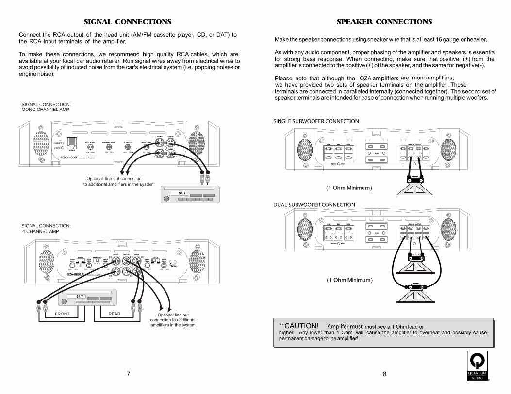
SINGLE SUBWOOFER CONNECTION
Amplifer must
QZA amplifiers
SIGNAL CONNECTIONS SPEAKER CONNECTIONS
DUAL SUBWOOFER CONNECTION
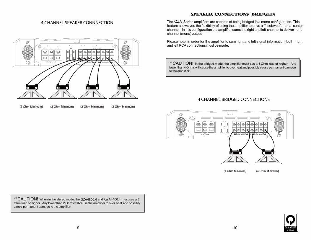
4 CHANNEL SPEAKER CONNNECTION
4 CHANNEL BRIDGED CONNECTIONS
QZA
QZA4800.4 QZA4400.4
SPEAKER CONNECTIONS (BRIDGED)


TROUBLESHOOTING THE SYSTEM SPECIFICATIONS
QZA2100D QZA3100D QZA4100DOutput Power :
1 ohm 1 x 2000W 1 x 3000W 1 x 4000W2 ohm 1 x 1000W 1 x 1500W 1 x2000W
Frequency Resp. 10Hz - 150Hz 10Hz - 150Hz 10Hz - 150HzS/N Ra o (A-weight) >90dB >90dB >90dBTHD with 80k filter <.05% <.05% <.05%Low Input Level 285mV - 6V 285mV - 6V 285mV - 6VCrossover Freq. 40Hz - 150Hz 40Hz - 150Hz 40Hz - 150HzCrossover Slope 12dB 12dB 12dBBass EQ 18dB @ 45Hz 18dB @ 45Hz 18dB @ 45HzSubsonic Filter 15Hz - 55hz 15Hz - 55hz 15Hz - 55hzBass Remote Yes Yes YesInput Voltage 11.2V - 14.4V 11.2V - 14.4V 11.2V - 14.4V
QZA4400.4Output Power :
4 ohms 4 x 100W2 ohms 4 x 200W
Bridged @ 4 ohms 2 x 1000W
Frequency Resp. 10Hz - 25KHzS/N Ra o (A-weight) >90dBTHD with 80k filter <.05%Low Input Level 285mV - 6VCrossover Freq. (Low) 30Hz - 150HzCrossover Freq. (High) 10Hz - 1.2KHzCrossover Slope 12dBBass EQ 18dB @ 45HzInput Voltage 11.2V - 14.4V
QZA4800.4
4 x 200W4 x 400W2 x 1200W
Rated @ 4 ohms 4 x 75W 2 x 95W
Rated @ 1 ohm 1 x 600W 1 x 900W 1 x 1200W
10Hz - 25KHz>90dB<.05%285mV - 6V30Hz - 150Hz10Hz - 1.2KHz12dB18dB @ 45Hz11.2V - 14.4V

![Power Amplifiers PartII[1]](https://static.fdocuments.net/doc/165x107/577d24611a28ab4e1e9c5708/power-amplifiers-partii1.jpg)