MOSFET Based High Frequency Inverter for Induction Heating...
7
NOVATEUR PUBLICATIONS NOVATEUR PUBLICATIONS NOVATEUR PUBLICATIONS NOVATEUR PUBLICATIONS INTERNATIONAL JOURNAL OF INNOVATIONS IN ENGINEERING RESEARCH AND TECHNOLOGY [IJIERT] INTERNATIONAL JOURNAL OF INNOVATIONS IN ENGINEERING RESEARCH AND TECHNOLOGY [IJIERT] INTERNATIONAL JOURNAL OF INNOVATIONS IN ENGINEERING RESEARCH AND TECHNOLOGY [IJIERT] INTERNATIONAL JOURNAL OF INNOVATIONS IN ENGINEERING RESEARCH AND TECHNOLOGY [IJIERT] VOLUME 1, ISSUE 1 NOV VOLUME 1, ISSUE 1 NOV VOLUME 1, ISSUE 1 NOV VOLUME 1, ISSUE 1 NOV-2014 2014 2014 2014 1 | Page MOSFET Based High Frequency Inverter for Induction Heating Equipment Using MATLAB / SIMULINK Environment Prof. V.V.Kulkarni, AISSMS College of Engineering, Pune University/Pune, Maharashtra, India L.B.Swami AISSMS College of Engineering, Pune University/Pune, Maharashtra, India Abstract High frequency resonant converters are used widely for induction heating. This paper presents a resonant inverter to achieve the desired high frequency with reduced switching losses and simulating the power electronic converter circuit using MATLAB/SIMULINK for induction heating equipment. The circuit designed has the load as induction coil and high frequency electricity is required to heat the work piece placed within the induction coil. The output power of the load coil is varied by changing the frequency of the inverter. The circuit uses the Power MOSFET instead of the IGBT.The series-resonant inverter is implemented to provide Zero Current Switching (ZCS) for all the switches at turn off conditions and Zero Voltage Switching (ZVS) at diode turn on. The main features of the proposed inverter are simple PWM control strategy and high efficiency. The operation mode of the inverter will be evaluated corresponding to the duty cycle of the switch. Keywords: Simulation, ZVS, ZCS, induction half-bridge resonant inverter. Introduction Electromagnetic induction refers to the phenomena by which electric current is generated in a closed circuit by the fluctuation of current in another circuit placed next to it. The heating process does not contaminate the material being heated and it is very efficient since the heat is actually generated inside the work piece Induction heating is working by applying a source of high frequency electricity to drive a large alternating current through a work coil. The passage of current through the work coil generates a very intense and rapidly changing magnetic field in the space within the work coil Induction heating is a reliable and innovative technology is characterized by the fact that the required energy is non-contacting transmitted into the work piece. The work piece to be heated is placed within this intense alternating magnetic field. [1][5]. Recent advances of the high-power semiconductor devices technology; the research on high-power solid-state high frequency power supply has achieved great progress. The IGBT offers low on resistance and requires very little gate drive power, it is widely used in generators with frequencies up to 100 kHz, but the frequency about 400 kHz is hard to achieve for the state-of -the art IGBT. The SIT has the defects like high conduction loss compared to IGBT, complicated fabrication process, high cost and price that restrict it in its applications. This very high switching frequency can be achieved using MOSFETs. MOSFET has the advantages like high switching speed, easy to be paralleled, so MOSFET is used in the range of high frequencies (in the range of 100-800 kHz) and high-power applications.[2] Current Switching (ZCS) for all the switches at turn off conditions and Zero Voltage Switching (ZVS) at diode turn on. The main features of the proposed inverter are simple PWM control strategy and high efficiency. The operation mode of the inverter will be evaluated corresponding to the duty cycle of the switch. [2][4][6] In practice, the work coil is usually incorporated into resonant tank circuit that forms either series or parallel resonance tank circuit. Thereducedswitching losses of the resonant converter render it suitable for implementing an efficient IH system. [1][4]The purpose of this work is to get a series-
Transcript of MOSFET Based High Frequency Inverter for Induction Heating...

NOVATEUR PUBLICATIONSNOVATEUR PUBLICATIONSNOVATEUR PUBLICATIONSNOVATEUR PUBLICATIONS INTERNATIONAL JOURNAL OF INNOVATIONS IN ENGINEERING RESEARCH AND TECHNOLOGY [IJIERT]INTERNATIONAL JOURNAL OF INNOVATIONS IN ENGINEERING RESEARCH AND TECHNOLOGY [IJIERT]INTERNATIONAL JOURNAL OF INNOVATIONS IN ENGINEERING RESEARCH AND TECHNOLOGY [IJIERT]INTERNATIONAL JOURNAL OF INNOVATIONS IN ENGINEERING RESEARCH AND TECHNOLOGY [IJIERT]
VOLUME 1, ISSUE 1 NOVVOLUME 1, ISSUE 1 NOVVOLUME 1, ISSUE 1 NOVVOLUME 1, ISSUE 1 NOV----2014201420142014
1 | P a g e
MOSFET Based High Frequency Inverter for Induction Heating
Equipment Using MATLAB / SIMULINK Environment
Prof. V.V.Kulkarni, AISSMS College of Engineering, Pune University/Pune, Maharashtra, India
L.B.Swami AISSMS College of Engineering, Pune University/Pune, Maharashtra, India
Abstract High frequency resonant converters are used widely for induction heating. This paper presents a resonant inverter to achieve the desired high frequency with reduced switching losses and simulating the power electronic converter circuit using MATLAB/SIMULINK for induction heating equipment. The circuit designed has the load as induction coil and high frequency electricity is required to heat the work piece placed within the induction coil. The output power of the load coil is varied by changing the frequency of the inverter. The circuit uses the Power MOSFET instead of the IGBT.The series-resonant inverter is implemented to provide Zero Current Switching (ZCS) for all the switches at turn off conditions and Zero Voltage Switching (ZVS) at diode turn on. The main features of the proposed inverter are simple PWM control strategy and high efficiency. The operation mode of the inverter will be evaluated corresponding to the duty cycle of the switch.
Keywords: Simulation, ZVS, ZCS, induction half-bridge resonant inverter.
Introduction Electromagnetic induction refers to the phenomena by which electric current is generated in a closed circuit by the fluctuation of current in another circuit placed next to it. The heating process does not contaminate the material being heated and it is very efficient since the heat is actually generated inside the work piece Induction heating is working by applying a source of high frequency electricity to drive a large alternating current through a work coil. The passage of current through the work coil generates a very intense and rapidly changing magnetic field in the space within the work coil Induction heating is a reliable and innovative technology is characterized by the fact that the required energy is non-contacting transmitted into the work piece. The work piece to be heated is placed within this intense alternating magnetic field. [1][5]. Recent advances of the high-power semiconductor devices technology; the research on high-power solid-state high frequency power supply has achieved great progress. The IGBT offers low on resistance and requires very little gate drive power, it is widely used in generators with frequencies up to 100 kHz, but the frequency about 400 kHz is hard to achieve for the state-of -the art IGBT. The SIT has the defects like high conduction loss compared to IGBT, complicated fabrication process, high cost and price that restrict it in its applications. This very high switching frequency can be achieved using MOSFETs. MOSFET has the advantages like high switching speed, easy to be paralleled, so MOSFET is used in the range of high frequencies (in the range of 100-800 kHz) and high-power applications.[2] Current Switching (ZCS) for all the switches at turn off conditions and Zero Voltage Switching (ZVS) at diode turn on. The main features of the proposed inverter are simple PWM control strategy and high efficiency. The operation mode of the inverter will be evaluated corresponding to the duty cycle of the switch. [2][4][6] In practice, the work coil is usually incorporated into resonant tank circuit that forms either series or parallel resonance tank circuit. Thereducedswitching losses of the resonant converter render it suitable for implementing an efficient IH system. [1][4]The purpose of this work is to get a series-

NOVATEUR PUBLICATIONSNOVATEUR PUBLICATIONSNOVATEUR PUBLICATIONSNOVATEUR PUBLICATIONS INTERNATIONAL JOURNAL OF INNOVATIONS IN ENGINEERING RESEARCH AND TECHNOLOGY [IJIERT]INTERNATIONAL JOURNAL OF INNOVATIONS IN ENGINEERING RESEARCH AND TECHNOLOGY [IJIERT]INTERNATIONAL JOURNAL OF INNOVATIONS IN ENGINEERING RESEARCH AND TECHNOLOGY [IJIERT]INTERNATIONAL JOURNAL OF INNOVATIONS IN ENGINEERING RESEARCH AND TECHNOLOGY [IJIERT]
VOLUME 1, ISSUE 1 NOVVOLUME 1, ISSUE 1 NOVVOLUME 1, ISSUE 1 NOVVOLUME 1, ISSUE 1 NOV----2014201420142014
2 | P a g e
resonant inverter for induction heating. The operating frequency is fixed, but the duty cycle control can be adjusted, based on power desired and load conditions. The required fixed-frequency control has some additional advantages, as reducing the electromagnetic noise spectrum and avoiding the acoustic noise due to different operating frequencies which cause low-frequency interferences amplified by the iron.[6]
Motivation for the Research. Probably the biggest concern with conventional energy sources is the amount of Pollutants that are released into the atmosphere. These growing concerns over the environmental changes caused by power generation with conventional energy sources has lead to the need for developing an alternative energy source; one that is highly efficient and pollution free. The most common method of heating uses fossil fuels such as coal. However, the burning of fossil fuels releases CO2 gas which has been directly associated with global warming due to the greenhouse effect. The demand for better quality, safe and less energy consuming products is rising. Safe, efficient and quick heating appliances attract more customers. Heating of electrically conducting or non-conducting materials is one of the essential processes in many industries. Electrical heating is preferred over conventional heating methods using fuel. This preference is due to certain advantages of electric heating such as high efficiency, low cost, free from pollution, compactness, quick start up and shut down easy temperature control etc. Due to these advantages electric heating is more convenient. For an extensive use of these advantages, it is necessary to develop a suitable induction heater.
Induction Heating Principle. Many practical work-pieces are cylindrical in form and are heated by being placed inside multi- or single-turn coils. The magnetic field, induced in the coil when energized, causes eddy currents to occur in the work-piece and these give rise to the heating effect. Theoretical analysis and practical experience a like show that most of the heat, generated by eddy currents in the work-piece, is concentrated in a peripheral layer of thickness δ given by,
δ = 5.64 cm ………………. (1)
Where µ and ρ are the magnetic permeability and electrical resistivity of the work-piece, respectively; f is the applied frequency. [2] [3]
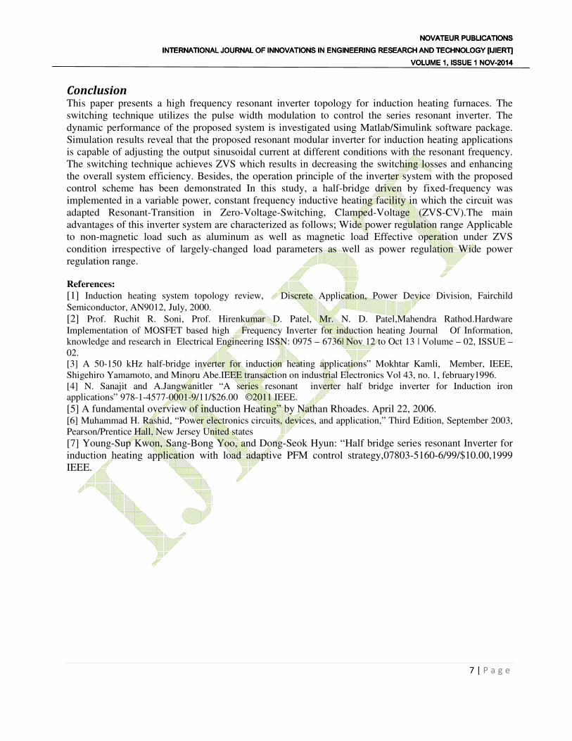
Choice of Converter. The half-bridge, series resonant converters were selected above the single-switch topologies due to the following reasons. i) The voltage across the semiconductors is clamped. Even though two switches are needed, at least half The voltage blocking capability is required. ii) Due to switching is done at a duty ratio of 50%, Feedback is not needed. Anti-parallel composite-switches must be used, as shown in Fig. 2 consisting of a singular- switch (S) and an anti-parallel diode (D). Metal Oxide Semiconductor Field Effect Transistors (MOSFETs) are shown because they are well suited for high frequency application. [4][7]
NOVATEUR PUBLICATIONSNOVATEUR PUBLICATIONSNOVATEUR PUBLICATIONSNOVATEUR PUBLICATIONS INTERNATIONAL JOURNAL OF INNOVATIONS IN ENGINEERING RESEARCH AND TECHNOLOGY [IJIERT]INTERNATIONAL JOURNAL OF INNOVATIONS IN ENGINEERING RESEARCH AND TECHNOLOGY [IJIERT]INTERNATIONAL JOURNAL OF INNOVATIONS IN ENGINEERING RESEARCH AND TECHNOLOGY [IJIERT]INTERNATIONAL JOURNAL OF INNOVATIONS IN ENGINEERING RESEARCH AND TECHNOLOGY [IJIERT]
VOLUME 1, ISSUE 1 NOVVOLUME 1, ISSUE 1 NOVVOLUME 1, ISSUE 1 NOVVOLUME 1, ISSUE 1 NOV----2014201420142014
3 | P a g e
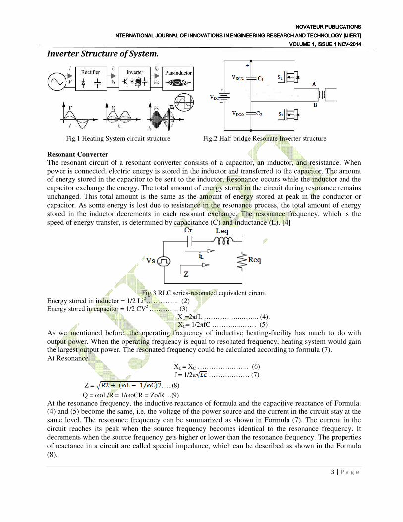
Inverter Structure of System.
Fig.1 Heating System circuit structure Fig.2 Half-bridge Resonate Inverter structure
Resonant Converter
The resonant circuit of a resonant converter consists of a capacitor, an inductor, and resistance. When power is connected, electric energy is stored in the inductor and transferred to the capacitor. The amount of energy stored in the capacitor to be sent to the inductor. Resonance occurs while the inductor and the capacitor exchange the energy. The total amount of energy stored in the circuit during resonance remains unchanged. This total amount is the same as the amount of energy stored at peak in the conductor or capacitor. As some energy is lost due to resistance in the resonance process, the total amount of energy stored in the inductor decrements in each resonant exchange. The resonance frequency, which is the speed of energy transfer, is determined by capacitance (C) and inductance (L). [4]
Fig.3 RLC series-resonated equivalent circuit
Energy stored in inductor = 1/2 Li2………….. (2) Energy stored in capacitor = 1/2 CV2 …………. (3)
XL=2πfL ……………..…….. (4). XC= 1/2πfC …………..…… (5)
As we mentioned before, the operating frequency of inductive heating-facility has much to do with output power. When the operating frequency is equal to resonated frequency, heating system would gain the largest output power. The resonated frequency could be calculated according to formula (7). At Resonance
XL = XC ………………….. (6)
f = 1/2π ……………… (7)
Z = …..(8)
Q = ωoL/R = 1/ωoCR = Zo/R ...(9)
At the resonance frequency, the inductive reactance of formula and the capacitive reactance of Formula. (4) and (5) become the same, i.e. the voltage of the power source and the current in the circuit stay at the same level. The resonance frequency can be summarized as shown in Formula (7). The current in the circuit reaches its peak when the source frequency becomes identical to the resonance frequency. It decrements when the source frequency gets higher or lower than the resonance frequency. The properties of reactance in a circuit are called special impedance, which can be described as shown in the Formula (8).

NOVATEUR PUBLICATIONSNOVATEUR PUBLICATIONSNOVATEUR PUBLICATIONSNOVATEUR PUBLICATIONS INTERNATIONAL JOURNAL OF INNOVATIONS IN ENGINEERING RESEARCH AND TECHNOLOGY [IJIERT]INTERNATIONAL JOURNAL OF INNOVATIONS IN ENGINEERING RESEARCH AND TECHNOLOGY [IJIERT]INTERNATIONAL JOURNAL OF INNOVATIONS IN ENGINEERING RESEARCH AND TECHNOLOGY [IJIERT]INTERNATIONAL JOURNAL OF INNOVATIONS IN ENGINEERING RESEARCH AND TECHNOLOGY [IJIERT]
VOLUME 1, ISSUE 1 NOVVOLUME 1, ISSUE 1 NOVVOLUME 1, ISSUE 1 NOVVOLUME 1, ISSUE 1 NOV----2014201420142014
4 | P a g e
Series Resonant Inverter.
The Class-D inverter will be generally used to energize the induction coil to generate high-frequency magnetic induction between the coil and the cooking vessel, high-frequency eddy currents and finally heat in the vessel bottom area. Class-D inverters take the energy from the mains voltage. The DC voltage is converted again into a high-frequency AC voltage by a Class-D inverter. Then the inverter supplies the high-frequency current to the induction coil.
Mode I Mode- II Mode- III
Mode – IV
Fig.4 Operation mode.
Fig.5 Waveform for main power circuit
Modes of Operation.
Mode I: to- t1 The resonant current flowing in an inverse direction changes its direction at the point of t=t0 flowing through S1. In this mode the DC-LINK voltage of Vdc lets the resonant circuit accumulate energy by supplying power through S1. Mode II: t1- t2 When S1 is turned off at the point of t=t1, the resonant current flowing through S1 begins free-wheeling through the D2 diode. In this process, a small amount of switching Turn-off loss occurs as the S1 switch is turned off while retaining some values in voltage and current. For the following mode, S2 is turned on when t1<t<t2. As the S2 switch remains at zero voltage/current,

NOVATEUR PUBLICATIONSNOVATEUR PUBLICATIONSNOVATEUR PUBLICATIONSNOVATEUR PUBLICATIONS INTERNATIONAL JOURNAL OF INNOVATIONS IN ENGINEERING RESEARCH AND TECHNOLOGY [IJIERT]INTERNATIONAL JOURNAL OF INNOVATIONS IN ENGINEERING RESEARCH AND TECHNOLOGY [IJIERT]INTERNATIONAL JOURNAL OF INNOVATIONS IN ENGINEERING RESEARCH AND TECHNOLOGY [IJIERT]INTERNATIONAL JOURNAL OF INNOVATIONS IN ENGINEERING RESEARCH AND TECHNOLOGY [IJIERT]
VOLUME 1, ISSUE 1 NOVVOLUME 1, ISSUE 1 NOVVOLUME 1, ISSUE 1 NOVVOLUME 1, ISSUE 1 NOV----2014201420142014
5 | P a g e
no switching loss takes place at turn-on. And the reverse recovery of D1 does not necessarily have to be fast. After turning off S1, the resonant current passes for a short period through the snubber C1 before freewheeling to D2. Mode III: t2- t3 Right after t=t2, the current freely resonates and flows in an inverse direction through S2 which is already turned on. Here, the resonant capacitor, Cr, serves as a source of voltage. Mode IV: t3- t4 When S2 is turned off at t=t3, the resonant current flowing through S2 starts freewheeling through the D1 diode. In this process, a small amount of switching loss occurs at turn-off. For the following mode, the S1 switch is turned on at a certain point (t3<t<t4). At this point, there is no switching loss at turn-on as the S1 switch remains at zero voltage/current. And the reverse recovery of D2 does not have to be fast. In this mode, the energy of the resonant circuit is converted to Vdc passing D1. The operating mode after t>t4 cycles from mode I to mode IV again as described above. Also in this process, the resonant current passes through the snubber C2 for a short period of time before freewheeling to D1. [1][2][4]
Simulation Results and Discussion The proposed induction heating system including the high frequency converter and the control scheme is simulated using Matlab/Simulink. The high frequency converter is represented by two MOSFETs together to to form half bridge series inverter feed the load by the required power at 65 KHz from the 50 Hz supply through a diode rectifier. The induction heating system is simulated by an RL circuit and connected to a capacitor (C) which represents the capacitance added for the system to resonate. The input voltage for inverter is DC voltage and in order to fire MOSFET two gate pulses with high frequency having 180 degree phase shift to avoid cross conduction of MOSFET.This is achived by using two pulse generatorsnamed as pulse generator 1 and pulse generator 2,generates square wave of frequency 65KHz. It is observed that at a time one MOSFET is on and it acts like as a switch to transfer the energy. This output energy is AC in the the form of square wave with high voltage ,low current side as shown in Fig.9 and this energy is coupled to tank through coupling transformer. The waveform of the current is sine wave due to the resonant circuit but the amplitude of the current is fluctuated. The transformer is step down transformer so that low voltage, high current side so that it induces high current in object to be heated. Also the nature of current induced in a coil is sinosidal in nature on the both inverter coupling transformer primery and secondery side as shown in Fig.10 and Fig.11.The switching signal frequency for any gate is 65 KHz. Fig.7and Fig.8 shows the switching signals for the gates of inverter. As discussed before, the output frequency of the proposed inverter system is 65 KHz, In addition, it is obvious one MOSFET is turned on for one cycle and turned-off for another cycle. The switching of the two MOSFET’S is interchangeable as expected. The system parameter is followed as; Vdc = 300V Cs1= Cs2= 1µf, Cr = 4.4µf

NOVATEUR PUBLICATIONSNOVATEUR PUBLICATIONSNOVATEUR PUBLICATIONSNOVATEUR PUBLICATIONS INTERNATIONAL JOURNAL OF INNOVATIONS IN ENGINEERING RESEARCH AND TECHNOLOGY [IJIERT]INTERNATIONAL JOURNAL OF INNOVATIONS IN ENGINEERING RESEARCH AND TECHNOLOGY [IJIERT]INTERNATIONAL JOURNAL OF INNOVATIONS IN ENGINEERING RESEARCH AND TECHNOLOGY [IJIERT]INTERNATIONAL JOURNAL OF INNOVATIONS IN ENGINEERING RESEARCH AND TECHNOLOGY [IJIERT]
VOLUME 1, ISSUE 1 NOVVOLUME 1, ISSUE 1 NOVVOLUME 1, ISSUE 1 NOVVOLUME 1, ISSUE 1 NOV----2014201420142014
6 | P a g e
Fig.5 Schematic diagram of HF inverter
Fig.6 Input DC Voltage for Inverter Fig.7 Switching signals for inverter (Gate1)
Fig.8 Switching signals for inverter (Gate2) Fig.9 Square Wave Output of Inverter
Fig.10 Output Current on Transformer Primary Side Fig.11Output Current on Transformer Secondary Side
Fig.12 Output Voltage across Series RLC Element
NOVATEUR PUBLICATIONSNOVATEUR PUBLICATIONSNOVATEUR PUBLICATIONSNOVATEUR PUBLICATIONS INTERNATIONAL JOURNAL OF INNOVATIONS IN ENGINEERING RESEARCH AND TECHNOLOGY [IJIERT]INTERNATIONAL JOURNAL OF INNOVATIONS IN ENGINEERING RESEARCH AND TECHNOLOGY [IJIERT]INTERNATIONAL JOURNAL OF INNOVATIONS IN ENGINEERING RESEARCH AND TECHNOLOGY [IJIERT]INTERNATIONAL JOURNAL OF INNOVATIONS IN ENGINEERING RESEARCH AND TECHNOLOGY [IJIERT]
VOLUME 1, ISSUE 1 NOVVOLUME 1, ISSUE 1 NOVVOLUME 1, ISSUE 1 NOVVOLUME 1, ISSUE 1 NOV----2014201420142014
7 | P a g e
Conclusion This paper presents a high frequency resonant inverter topology for induction heating furnaces. The switching technique utilizes the pulse width modulation to control the series resonant inverter. The dynamic performance of the proposed system is investigated using Matlab/Simulink software package. Simulation results reveal that the proposed resonant modular inverter for induction heating applications is capable of adjusting the output sinusoidal current at different conditions with the resonant frequency. The switching technique achieves ZVS which results in decreasing the switching losses and enhancing the overall system efficiency. Besides, the operation principle of the inverter system with the proposed control scheme has been demonstrated In this study, a half-bridge driven by fixed-frequency was implemented in a variable power, constant frequency inductive heating facility in which the circuit was adapted Resonant-Transition in Zero-Voltage-Switching, Clamped-Voltage (ZVS-CV).The main advantages of this inverter system are characterized as follows; Wide power regulation range Applicable to non-magnetic load such as aluminum as well as magnetic load Effective operation under ZVS condition irrespective of largely-changed load parameters as well as power regulation Wide power regulation range.
References:
[1] Induction heating system topology review, Discrete Application, Power Device Division, Fairchild
Semiconductor, AN9012, July, 2000.
[2] Prof. Ruchit R. Soni, Prof. Hirenkumar D. Patel, Mr. N. D. Patel,Mahendra Rathod.Hardware Implementation of MOSFET based high Frequency Inverter for induction heating Journal Of Information, knowledge and research in Electrical Engineering ISSN: 0975 – 6736| Nov 12 to Oct 13 | Volume – 02, ISSUE – 02. [3] A 50-150 kHz half-bridge inverter for induction heating applications” Mokhtar Kamli, Member, IEEE, Shigehiro Yamamoto, and Minoru Abe.IEEE transaction on industrial Electronics Vol 43, no. 1, february1996. [4] N. Sanajit and A.Jangwanitler “A series resonant inverter half bridge inverter for Induction iron applications” 978-1-4577-0001-9/11/$26.00 ©2011 IEEE.
[5] A fundamental overview of induction Heating” by Nathan Rhoades. April 22, 2006. [6] Muhammad H. Rashid, “Power electronics circuits, devices, and application,” Third Edition, September 2003, Pearson/Prentice Hall, New Jersey United states
[7] Young-Sup Kwon, Sang-Bong Yoo, and Dong-Seok Hyun: “Half bridge series resonant Inverter for induction heating application with load adaptive PFM control strategy,07803-5160-6/99/$10.00,1999 IEEE.