Morphing Unmanned Aerial Vehicles - Universitylib.tkk.fi/Dipl/2010/urn100303.pdf · Aalto...
103
Aalto University School of Science and Technology Faculty of Engineering and Architecture Department of Applied Mechanics Blé Bernard Wongui Morphing Unmanned Aerial Vehicles Thesis submitted in partial fulfilment of the requirements for the degree of Master of Science in Technology 30 May 2010 Supervisor: Professor Olli Saarela Instructor: Professor Olli Saarela
Transcript of Morphing Unmanned Aerial Vehicles - Universitylib.tkk.fi/Dipl/2010/urn100303.pdf · Aalto...

Aalto UniversitySchool of Science and TechnologyFaculty of Engineering and ArchitectureDepartment of Applied Mechanics
Blé Bernard Wongui
Morphing Unmanned Aerial Vehicles
Thesis submitted in partial fulfilment of the requirements for the degree of Masterof Science in Technology
30 May 2010
Supervisor: Professor Olli SaarelaInstructor: Professor Olli Saarela

Aalto University Abstract of Master’s ThesisSchool of Science and Technology
Author: Blé Bernard WONGUI
Title: Morphing Unmanned Aerial Vehicles
Date: 30 May 2010 Pages: 96 + 7Faculty: Faculty of Engineering and ArchitectureDepartment: Department of Applied MechanicsProfessorship: Kul-34 Aeronautical EngineeringSupervisor: Professor Olli SaarelaInstructor: Professor Olli Saarela
The performance and dynamic efficiency of an aircraft are significantly influenced by theaircraft shape and configuration. Therefore, the wing which is an important element in theaircraft load response in terms of drag and lift has been given increasing attention throughmorphing technology. Several governmental programs and academic research projects onmorphing aircraft have investigated methods of efficiently changing the wing geometric char-acteristics in-flight.The present thesis reviews the current knowledge on wing morphing concepts and investigatesthe type of methods that can be used to model morphing structures.This review includes the principles of the morphing concept, realization of a morphing struc-ture, aspects of morphing structure design, current methods to model morphing structures,challenges, and the perspectives of the morphing UAVs.It concludes that the wing cover skins must possess a high degree of deformability; but theymust be able to maintain their shape and structural integrity under the compression, tension,shear and bending characteristics of aerodynamic and flight loads including the effects ofadded masses. In order to meet these requirements, thermoplastic elastomers and shapememory polymers are suggested as good candidate materials for smart skins. Nevertheless,an excessively flexible skin is exposed to the hazard of sagging under pressure loads.It is suggested that bio-inspired micro air vehicles based on bat wing structure will gainintensive attention since such a structure prossesses a high flexibility with anisotropy andnon-linear elasticity.
Keywords: Morphing, UAV, Actuators, Sensors, Lagrange, Rayleigh-Ritz, FSDT.

2
PREFACE
The great rise of Unmanned Aerial Vehicles dates from the "Cold War" between theUSA and the former USSR after the Second World War. During that period, UAVswere confidentially developed by the US army as a means of strategic superiorityto allow surveillance and military intervention in the enemy fields without incurringthe death risk that human could not stand the view.This superiority has been gained through technological innovations in the field ofAutomation and Transmission systems. Later on, the Morphing Aircraft Structureprogram aimed to design and build active variable geometry wing structures withthe ability to morph in-flight to optimize the flight.The first aircraft capable of changing the sweep of its wing in-flight was the BellX-5 produced by the USA in 1951. Since then, the increasing interest in morphingstructure is the result of their significant advantages over conventional UnmannedAerial Vehicles.This thesis leading to the award of a Master’s of Science degree in Technology toMr. Blé Bernard WONGUI, holder of a BSc. in Mechanical Engineering, providesan appropriate documentation to address the modeling of morphing structures. Hiswork provides current information on the state of the art in UAVs.
Jovin GREYE.

3
Acknowledgments
The author is grateful to Professors Olli SAARELA and Erkki SOINNE for motivat-ing the funding the present Master’s thesis. The assistance and the succinct advicesof Professor SAARELA; but also the support of Professor SOINNE for aerodynamicmodeling were extremely valuable in completing this work.The author would like to express his gratitude particularly to the professionals withwhom he has exchanged on the topic and who have shared the result of their investi-gations. The first of them is Professor Michael I. FRISWELL1, School of EngineeringSwansea University. Professor Friswell made significant contributions by providingthe author with materials including his publications and lecture notes. Dr Fab-rizio SCARPA, Reader in Smart Structures, Department of Aerospace Engineering,Bristol University, and Dr Zhong YOU, Lecturer (Structures), Department of En-gineering Science, Oxford University provided the author with their publications orlecture notes.The author addresses a grateful regard to the friends and course mates who haveassisted him in several respects including proof-reading and bringing forth construc-tive comments on the linguistic level; but also for the technical assistance in soft-ware issues. Thanks to Dr YALAHO, J. GREYE, J. CHOO, B. ZOKO, and M.WEGELIUS.Finally, the author would like to embrace his daughters Julina Nagnon WONGUI,Lilja Wahzi WONGUI and Michelle Nadrey WONGUI for their patience, and thankhis companion Dace KALNINA for her support.
Espoo, 30 May 2010,
Blé Bernard WONGUI.
1Email correspondence included at the end of the present work.


Contents
Abbreviations . . . . . . . . . . . . . . . . . . . . . . . . . . . . . . . . . . 3
1 Introduction 51.1 Morphing Aircraft . . . . . . . . . . . . . . . . . . . . . . . . . . . . 51.2 Background Of Unmanned Aerial Vehicles . . . . . . . . . . . . . . . 51.3 Research Problem And Approach . . . . . . . . . . . . . . . . . . . . 61.4 Thesis Overview . . . . . . . . . . . . . . . . . . . . . . . . . . . . . . 7
2 Unmanned Aerial Vehicles 82.1 Classification Of UAVs . . . . . . . . . . . . . . . . . . . . . . . . . . 122.2 Mission Aspects of UAVs . . . . . . . . . . . . . . . . . . . . . . . . 14
3 Morphing Concepts 153.1 Morphing Shape Alternatives . . . . . . . . . . . . . . . . . . . . . . 183.2 Wing Planform Alternations . . . . . . . . . . . . . . . . . . . . . . . 19
3.2.1 Wing Span Morphing . . . . . . . . . . . . . . . . . . . . . . 203.2.2 Inflatable Wing Concept . . . . . . . . . . . . . . . . . . . . . 213.2.3 Sweep Angle Variation . . . . . . . . . . . . . . . . . . . . . . 22
3.3 Out-Of-Plane Transformations . . . . . . . . . . . . . . . . . . . . . . 243.3.1 Camber And Chord Control . . . . . . . . . . . . . . . . . . . 253.3.2 Wing Twist Control . . . . . . . . . . . . . . . . . . . . . . . 26
3.4 Airfoil Profile Adjustments . . . . . . . . . . . . . . . . . . . . . . . . 283.5 Morphing UAVs . . . . . . . . . . . . . . . . . . . . . . . . . . . . . . 30
4 Actuators And Sensors 334.1 Fiber Optic Sensors . . . . . . . . . . . . . . . . . . . . . . . . . . . . 334.2 Smart Materials . . . . . . . . . . . . . . . . . . . . . . . . . . . . . 344.3 Shape Memory Alloys . . . . . . . . . . . . . . . . . . . . . . . . . . 374.4 Piezo-Electric Materials . . . . . . . . . . . . . . . . . . . . . . . . . 38
4.4.1 Active Fiber Composites . . . . . . . . . . . . . . . . . . . . . 384.4.2 Macro Fiber Composite . . . . . . . . . . . . . . . . . . . . . 38
5 Structure Solutions 395.1 Design Aspects of Morphing Structures . . . . . . . . . . . . . . . . . 395.2 Multi-Stable Composite Materials . . . . . . . . . . . . . . . . . . . . 415.3 Adaptive Aero-Elastic Structures . . . . . . . . . . . . . . . . . . . . 44
5.3.1 Variable Geometry Truss . . . . . . . . . . . . . . . . . . . . . 455.3.2 Variable Stiffness Spar . . . . . . . . . . . . . . . . . . . . . . 465.3.3 Bend-Twist Coupled Beams . . . . . . . . . . . . . . . . . . . 475.3.4 Preloaded Internal Spine Structures . . . . . . . . . . . . . . . 49
i

CONTENTS ii
5.3.5 Kagome Lattice Structures . . . . . . . . . . . . . . . . . . . . 505.3.6 Auxetic Materials . . . . . . . . . . . . . . . . . . . . . . . . . 525.3.7 Belt Rib Concept . . . . . . . . . . . . . . . . . . . . . . . . . 535.3.8 Finger Concept . . . . . . . . . . . . . . . . . . . . . . . . . . 54
5.4 NextGen’s Wing Mechanism . . . . . . . . . . . . . . . . . . . . . . . 555.5 Lockheed’s Wing Mechanisms . . . . . . . . . . . . . . . . . . . . . . 565.6 Scaling Limitations . . . . . . . . . . . . . . . . . . . . . . . . . . . . 575.7 Control Issues Of Morphing UAVs . . . . . . . . . . . . . . . . . . . 58
6 Modeling Principles of Morphing Structures 596.1 Basic Static And FE Formulations . . . . . . . . . . . . . . . . . . . 596.2 Force-Displacements Relationship . . . . . . . . . . . . . . . . . . . . 61
6.2.1 Differential Method . . . . . . . . . . . . . . . . . . . . . . . . 616.2.2 Rayleigh-Ritz Energy Method . . . . . . . . . . . . . . . . . . 63
6.3 Span Morphing Wing Model . . . . . . . . . . . . . . . . . . . . . . 646.3.1 Aero-Elastic Model . . . . . . . . . . . . . . . . . . . . . . . . 646.3.2 Aerodynamic Model . . . . . . . . . . . . . . . . . . . . . . . 65
6.4 Camber Morphing Model . . . . . . . . . . . . . . . . . . . . . . . . 666.4.1 Structural Model . . . . . . . . . . . . . . . . . . . . . . . . . 666.4.2 Theodorsen’s Model . . . . . . . . . . . . . . . . . . . . . . . 69
6.5 Continuously Morphing Wing Model . . . . . . . . . . . . . . . . . . 716.5.1 Structural Model . . . . . . . . . . . . . . . . . . . . . . . . . 716.5.2 Piezo And Thermo Actuator Model . . . . . . . . . . . . . . . 78
6.6 Snap-Through Model . . . . . . . . . . . . . . . . . . . . . . . . . . . 80
7 Conclusion 867.1 Challenges . . . . . . . . . . . . . . . . . . . . . . . . . . . . . . . . 867.2 Perspectives . . . . . . . . . . . . . . . . . . . . . . . . . . . . . . . . 87
Bibliography 87

List of Figures
2.1 Black Hornet [9]. . . . . . . . . . . . . . . . . . . . . . . . . . . . . . 11
3.1 Ader’s Eole [33]. . . . . . . . . . . . . . . . . . . . . . . . . . . . . . . 163.2 Eagle in various wing configurations [109]. . . . . . . . . . . . . . . . 163.3 Classification for shape morphing of wing [111]. . . . . . . . . . . . . 193.4 In-flight deployment of I2000 inflatable Wing [46]. . . . . . . . . . . . 223.5 Aerodynamic coefficients of an inflatable wing [12]. . . . . . . . . . . 223.6 F-14 wing sweep mechanism [23]. . . . . . . . . . . . . . . . . . . . . 233.7 Chord-wise bending achieved by the heating of SMA strips in an
antagonistic design. (a) Un-morphed and (b) morphed [133]. . . . . . 263.8 Twisting of a wing section achieved by antagonistic SMA actuation.
(a) The left rib is flexed downward and right rib upward. (b) The leftrib is actuated upward and the right one downward [133]. . . . . . . . 27
3.9 Nominal wing (left) and morphed wing (right) [116]. . . . . . . . . . 273.10 Airfoil profile control [117]. . . . . . . . . . . . . . . . . . . . . . . . . 283.11 Position of the wing skins [118]. . . . . . . . . . . . . . . . . . . . . 293.12 NextGen’s morphing wing planform configurations [62]. . . . . . . . . 313.13 Lockheed’s folding wing concept [62]. . . . . . . . . . . . . . . . . . . 32
4.1 Basic fiber optic smart structure system [40]. . . . . . . . . . . . . . . 34
5.1 Morphing smart design concept [98]. . . . . . . . . . . . . . . . . . . 405.2 One dimensional morphing concept [78]. . . . . . . . . . . . . . . . . 425.3 Bi-stable composite materials [88]. . . . . . . . . . . . . . . . . . . . 435.4 Wing with two VGTs as spars [95]. . . . . . . . . . . . . . . . . . . . 455.5 Double octahedral VGT unit [95] . . . . . . . . . . . . . . . . . . . . 455.6 Wing box with movable central spar [92]. . . . . . . . . . . . . . . . . 465.7 Wing box with rotating leading and trailing edge spars [92]. . . . . . 465.8 a) Layup for bend-twist coupling and b) layup for extension-twist
coupling [93]. . . . . . . . . . . . . . . . . . . . . . . . . . . . . . . . 485.9 a) Single box layup, b) double box layup and c) patch layup [93]. . . 495.10 A beam column with eccentric load [52]. . . . . . . . . . . . . . . . . 505.11 A planar Kagome lattice [38]. . . . . . . . . . . . . . . . . . . . . . . 515.12 Chiral airfoil structure [130]. . . . . . . . . . . . . . . . . . . . . . . . 535.13 The belt rib concept [103]. . . . . . . . . . . . . . . . . . . . . . . . 535.14 Finger concept [102]. . . . . . . . . . . . . . . . . . . . . . . . . . . . 545.15 NextGen’s bat wing mechanism [89]. . . . . . . . . . . . . . . . . . . 555.16 Lockheed’s morphing wing joint design [62]. . . . . . . . . . . . . . . 56
1

LIST OF FIGURES 2
6.1 Member with actuator force [71]. . . . . . . . . . . . . . . . . . . . . 616.2 Forces and displacements for a post-buckled member [71]. . . . . . . . 626.3 Trailing edge framework for morphing wing [71]. . . . . . . . . . . . . 636.4 Camber line with PBP [83]. . . . . . . . . . . . . . . . . . . . . . . . 666.5 Wing morphing part model [83]. . . . . . . . . . . . . . . . . . . . . . 676.6 Stress and moment resultants for a laminate element [84]. . . . . . . . 686.7 Generic trapezoidal wing (left) and wing- box (right)[127]. . . . . . . 726.8 Geometry of laminate-actuator combination [120]. . . . . . . . . . . 81

List of Tables
2.1 UAV programs of the US military [14]. . . . . . . . . . . . . . . . . . 92.2 Extremum records of UAVs [8]. . . . . . . . . . . . . . . . . . . . . . 102.3 USAF classification of UAVs [10]. . . . . . . . . . . . . . . . . . . . . 122.4 UAV classification by altitude and endurance [8] . . . . . . . . . . . . 132.5 UAV classification by weight. . . . . . . . . . . . . . . . . . . . . . . 13
3.1 Effects of the change type on the aerodynamic characteristics in thescale 1-5 [34]. . . . . . . . . . . . . . . . . . . . . . . . . . . . . . . . 18
3.2 Morphing concepts, actuation and skin types. . . . . . . . . . . . . . 29
4.1 Most common smart materials [54]. . . . . . . . . . . . . . . . . . . . 36

ABBREVIATIONS 4
ADVENT Adaptive Versatile Engine TechnologyAFC Active Fiber Composites or Antagonistic Flexural unit CellAFRL Air Force Research LabsCPT Classical Plate TheoryDARPA Defense Advanced Research Projects AgencyDC Direct currentDHM Doublet-Hybrid MethodDLR Deutsches Zentrum für Luft-und Raumfahrt e.VDoD Department of DefenseEAP Electro-Active PolymersEO Electro OpticalFE Finite ElementFEA Finite Element AnalysisFEM Finite Element MethodFLIR Forward Looking InfraRedFMC Flexible Matrix CompositeFPASS Force Protection Aerial Surveillance SystemFSDT First-order Shear Deformation TheoryHAE High Altitude EnduranceHALE High Altitude Long EnduranceHSDT Higher-order Shear Deformation TheoryIR Infra RedISR Intelligence, Surveillance, ReconnaissanceISTAR Intelligence, Surveillance, Target Acquisition and ReconnaissanceLO-HAE Low Observable High Altitude EnduranceMAE Medium Altitude EnduranceMAS Morphing Aircraft StructureMAW Mission Adaptive WingMUAV Micro UAVNASA National Aeronautics and Space AdministrationNSMV Near Space Maneuvering VehiclePBP Post-Buckled PrecompressedPVDF Polyvinylidene FluoridePZN-PT Lead Zinc Niobate-Lead TitanatePZT Lead Zirconate TitanateSAR Synthetic Aperture RadarSMA Shape Memory AlloysSMP Shape Memory PolymersSTOL Short Take-Off and LandingSUAV Small UAVUAV Unmanned Aerial VehicleUCAV Unmanned Combat Air VehicleUSA United States of AmericaUSAF United States Air ForceVGT Variable Geometry TrussVLM Vortex Lattice MethodVSS Variable Stiffness SparVTOL Vertical Take-Off and Landing
Chapter 1
Introduction
1.1 Morphing AircraftMorphing aircraft are flight vehicles that are capable of altering their shape to meetchanging mission requirements of the aircraft and to perform flight control withoutthe use of conventional control surfaces. Therefore, the shape characteristics ofsuch an aircraft change in-flight to optimize performance. This morphing is realizedby monitoring the wing geometric parameters. These parameters include the wingspan, planform, aspect ratio, thickness, chord, camber, and consequently the wingarea.Aircraft morphing research is generally conducted for benefits including the improve-ment of the versatility of a given airframe by improving the performance for multipleflight regimes, the replacement of conventional control mechanisms, the increase ofcruise efficiencies and the reduction of structural vibration.
1.2 Background Of Unmanned Aerial VehiclesUnmanned Aerials Vehicles (UAVs) have been under development since the begin-ning of powered flight. Prior to the first manned airplane flight in 1903, rudimentaryUAV technology was applied to combat and surveillance [16]. However, World WarI is referred to as the effective introduction period of UAVs by US army [14]. Never-theless, those UAVs flew inaccurately; they were imperfect and unreliable. Despitethe lack of success of those vehicles, the UAV concept survived due to the tenacityof a small group of persons influencing politics for funding [4].Thus, research on morphing unmanned aerial vehicles has experienced over recentdecades increasing investigations in both military and civilian domains for appli-cations including surveillance, attack, fire detection, and traffic monitoring. Subse-quently, the NASA morphing project [1] focused on developing novel applications forsmart materials and inventing methods for applying those materials to aircraft. Ad-ditionally, the Morphing Aircraft Structure (MAS) program [2] aimed to design andbuild active, variable geometry wing structures with the ability to morph in-flight.Furthermore, the US Air Force’s Adaptive Versatile Engine Technology (ADVENT)program [3] supplied inlet, engine and exhaust technologies to optimize propulsionsystem performance.
5

CHAPTER 1. INTRODUCTION 6
This increasing interest in morphing structures is the result of their significantadvantages over conventional UAV structures. These advantages comprise the in-crease in the capability and versatility of the aircraft. According to [2], such anaircraft is a multi role platform that firstly, changes its state substantially to adaptto changing mission requirements. Secondly, it provides a superior system capabilityin term of an optimal performance into a single system with a low turning radius,long endurance, increased payload, and high speed. This is not possible without thewing reconfiguration. Finally, it uses a design that integrates innovative combina-tions of advanced materials, actuators, flow controllers and mechanisms to achievethe state change.
1.3 Research Problem And ApproachThe performance and dynamic efficiency of an aircraft are significantly influencedby the aircraft shape and configuration. Thus, the wing which is an importantelement in the aircraft load response has been given particular attention throughmorphing technology. Therefore, several governmental programs [2, 3], and aca-demic research projects [15, 17] on morphing aircraft have investigated methods ofefficiently changing the wing geometric characteristics in-flight.The present master’s thesis commissioned by the Department of Applied Mechanicsof Aalto University reviews the current knowledge on wing morphing concepts andinvestigates the type of methods that can be used to model morphing structures.This review includes:
1. Description of morphing concepts,
2. Principles of the morphing concept,
3. Realization of a morphing structure,
4. Design aspects of morphing structures,
5. Modeling principles of morphing structures,
6. Challenges and perspectives of the morphing UAVs.

CHAPTER 1. INTRODUCTION 7
1.4 Thesis OverviewThe remaining Chapters of this thesis are organized as follows:Chapter 2 reviews existing projects of UAV and gives their common classifications.Chapter 3 describes morphing concepts, following the introduction of the morphingshape alternatives. Section 3.5 is dedicated to the two most successful morphingUAV programs launched by NextGen Aeronautics and Martin Lockheed.Chapter 4 presents sensors and actuators. Additionally, it reviews the commonsmart materials.Chapter 5 introduces the factors that need to be considered when designing a mor-phing structure. Additionally, it reviews the structural solutions to achieve themorphing of a planform. The two last sections of this Chapter discuss the limita-tions set by the square-cube law on the use of materials in term of scalability andaddress the control issues of morphing vehicles.Chapter 6 presents the basis of finite element formulation of a morphing structure.Additionally, this Chapter includes the methods that may be used to model a camberand span morphing wing. It establishes the relationship between the actuationforce and the structural displacement using the differential and energy methods.Furthermore, it reviews the modeling of a continuously morphing flying wing and thesnap-through of unsymmetric composite laminates. Finally, this Chapter presentsthe Theodorsen’s function as a means to express the pressure distribution over amorphing wing.Chapter 7 concludes this review by assessing the challenges of the morphing tech-nology and giving a potential perspective.

Chapter 2
Unmanned Aerial Vehicles
This Chapter reviews existing projects of UAV and gives their common classifica-tions.Generally, an aircraft refers to any flying vehicle with configurations including fixed-wing, rotary-wing, helicopters, vertical take-off and landing (VTOL), and shorttake-off and landing (STOL) vehicles. According to [5], an aircraft may be eitherheavier or lighter than air, with balloons and airships belonging to the latter cate-gory. Moreover, the term unmanned aerial vehicle refers to a pilotless (no humancrew on board) aircraft. However, ballistic vehicles, cruise missiles, and artilleryprojectiles are not considered as UAVs. As described, UAVs are not limited by hu-man performance factors nor by his physiological and psychological characteristicsto accomplish missions that may be perishing for a human. Therefore, unmannedaerial vehicles can operate in environments contaminated by chemical, biological, orradioactive agents. They can carry cameras, sensors, communications equipment orother payloads including weapons.Worth mentioning is the fact that UAVs are generally used for military applications.Nevertheless, vertical take-off and landing applications extend to civilian domains.The VTOL unmanned aerial vehicle military applications include surveillance andreconnaissance, combat, and testing for new weapon systems. QH-50 GyrodyneTorpedo delivery drone [58] is an example of VTOL UAV. Additionally, civilianapplications include pipelines and power lines inspection and surveillance, oil andnatural gas search, and fire prevention. As the UAV field matures, the tendencyshifts to smaller, more flexible and versatile UAVs. New composite materials andimproved propulsion systems result in lighter, smaller, and more stealthy airframes,with the resulting fuel efficiency leading to levels of endurance that exceed humantolerance.As mentioned above, most of UAVs are used for military missions. Nonetheless,civilian applications gain momentum; but the consensus is that much more costeffective UAVs need to be utilized. Thus, well documented UAVs are those used bythe military around the world with the United States of America (USA) leading themarket and investments in research and development programs [4].
8

CHAPTER 2. UNMANNED AERIAL VEHICLES 9
Table 2.1 depicts characteristics of current UAV programs implemented by the De-partment of Defense (DoD) of the USA.
Table 2.1: UAV programs of the US military [14].
UAV advantages over manned aircraft in terms of endurance due to pilot fatigueand expendability have been demonstrated and proven in conflicts. For instance,a model of Pioneer [7] (a short range UAV) was used as a source of intelligence atthe tactical level during the Operation Desert Storm in Iraq. Additionally, a modelof Predator [82] performed surveillance missions such as monitoring area roads forweapon movements and conducting battle damage assessment in the Balkan conflicts[4].UAVs range in size from 15 grams (Black hornet) capable of carrying role equipmentto meet their specific mission, to a full size aircraft (Global Hawk).

CHAPTER 2. UNMANNED AERIAL VEHICLES 10
Table 2.2 presents the extremum records of UAVs.
Table 2.2: Extremum records of UAVs [8].
Currently, the smallest prototyped UAV called Black Hornet1 [9] is a 15 grams spynanocopter developed by Prox Dynamics for military use. It is expected to pro-vide soldiers with their own immediate intelligence, surveillance and reconnaissancecapability for operations indoors and outdoors, in confined areas; looking behind,between, and below obstacles with a bird’s eye view2 of areas of interest.
1Black Hornet is expected operational in 2011.2A view of an object from above, as though the observer were a bird.

CHAPTER 2. UNMANNED AERIAL VEHICLES 11
Figure 2.1 illustrates the Black Hornet.
Figure 2.1: Black Hornet [9].
The modern concept of U.S. military is to have the various aircraft systems workingtogether in support of personnel on the ground. The integration scheme is describedin terms of a "Tier" system. It is used by military planners to designate the variousindividual aircraft elements in an overall usage plan for integrated operations. TheTiers do not refer to specific models of aircraft; but to roles for which various modelsand their manufacturers competed [13].

CHAPTER 2. UNMANNED AERIAL VEHICLES 12
Table 2.3 presents the classification of UAVs according to the United States Airforce(USAF) standard.
Table 2.3: USAF classification of UAVs [10].
2.1 Classification Of UAVsUAVs can be classified based on number of characteristics including performanceand mission. The performance characteristics consist of:
1. Weight,
2. Range,
3. Altitude and endurance,
4. Wing loading,
5. Engine type,
6. Power/Thrust Loading.

CHAPTER 2. UNMANNED AERIAL VEHICLES 13
Table 2.4 and Table 2.5 show UAV classifications by altitude and endurance, andby weight respectively.
Table 2.4: UAV classification by altitude and endurance [8]
EO stands for Electro OpticalIR stands for Infra RedFLIR stands for Forward Looking InfraRedSAR stands for Synthetic Aperture Radar
Table 2.5: UAV classification by weight.

CHAPTER 2. UNMANNED AERIAL VEHICLES 14
Based on their geometric dimensions, three classes of UAVs may be considered.These categories include small size, medium size and large size UAVs. These threeclasses are directly related to the classification based on weight. Man-portable UAVsare briefly discussed below. The smallest unmanned aerial vehicles are Nano andMicro UAV’s (MUAV) such as the Black Hornet (Figure 2.1) and the AV BlackWidow developed for military surveillance, law enforcement, and civilian rescue ef-forts. Their weight and payload are just a few grams with vehicle size in the orderof few centimeters. Larger than MUAVs are the Small UAVs (SUAV). Their sizeranges from tenths of decimeter to a few meters, with platform weights in the or-der of a few kilograms. They are hand-launched or launched from a mobile launchstation. SUAVs including Raven, Pointer, and the Force Protection Aerial Surveil-lance System (FPASS) are man-portable, low-altitude, short-range systems assistedin providing base security, force protection, reconnaissance, and targeting. SmallUAVs are rapidly growing in type and offer a versatile family of capabilities. Theyprovide a unique target approaching capability. Their small size, quiet propulsionsystems, and ability to feed information directly to battlefield airmen enhance thecombat effectiveness [63].
2.2 Mission Aspects of UAVsAs mentioned earlier, the majority of UAVs is military orientated. Different militarymission requirements have created various types of UAVs including [14]:
1. Intelligence, Surveillance, Target Acquisition and Reconnaissance (ISTAR).Examples include most UAVs.
2. Unmanned combat aerial vehicles (UCAV). Examples include X45A, X45C,X46, and X47.
3. Multi-Purpose. Examples include MQ-1 Predator, MQ-5B Hunter, and MQ-9Predator B.
4. Vertical Take-Off and Landing (VTOL). Examples include Fire Scout, KillerBee, and X50.
5. Radar and Communication Relay. Examples include Tethered Aerostat RadarSystem, and Near Space Maneuvering Vehicle (NSMV)/Ascender/V-Airship.
6. Aerial Delivery and Resupply. Examples include CQ-10 Snow Goose.
ISTAR is a system using UAVs to gather enemy information, locate a target, or pa-trol hostile air space without risking lives of the operators. Often in battle grounds,combat commanders require real time information of the upcoming enemy forces.As an illustration, to be aware of the potential enemy defense, gathering informa-tion via reconnaissance UAVs is more effective in saving soldier lives. This categorycontains most UAVs.

Chapter 3
Morphing Concepts
Following the introduction of the morphing shape alternatives, this Chapter de-scribes morphing concepts including the planform alternation, out-of-plane trans-formation, and airfoil adjustment. Section 3.5 is dedicated to the two most successfulmorphing UAV programs launched by NextGen Aeronautics and Martin Lockheed.Friswell [15] defines four applications of the wing morphing concept:
1. Improvement of the aircraft performance to expand its flight envelope,
2. Replacement of conventional control surfaces for flight control to improve theperformance and stealth characteristics,
3. Reduction of the drag to improve the range,
4. Reduction of the vibration or the control of flutter.
Structural morphing is not a new concept in aircraft design. The Wright Brothers,for example, used wing warping through structural deformation to control the roll ofthe aircraft [65], Parker [64] proposed a variable camber wing to increase the flightspeed.Significant amount of investigations have been conducted since [28, 29, 30] on thewing structural morphing to achieve optimum aircraft performance by altering wingaerodynamic parameters. Thus, based on the changes induced by the structuralchanges in the aerodynamics of the wing, the morphing concepts are classified as[51]:
1. Large morphing to produce global aerodynamic effects: Examples include largeaspect ratio changes of the order of 50 - 60% or more.
2. Small morphing to produce global aerodynamic effects: Efforts like the syn-thetic jet actuation to produce hingeless trailing edge and morphing wing viatwisting the airfoil section come under this category.
3. Small morphing to produce local aerodynamic effects: Examples include groupsof synthetic jets for induced drag reduction and active skins to reduce the in-duced drag.
4. Intermediate morphing: Morphing for any other purposes like medium changesin span for flight in subsonic velocities.
15

CHAPTER 3. MORPHING CONCEPTS 16
By wing morphing, the author refers to a planform that is able to transform smoothlyits shape or any other characteristic affecting significantly its aerodynamic proper-ties. It is evident that a conventional aircraft has a wing matching the mission it isdedicated to. As a general observation, the concept of morphing wings is inspiredfrom birds; but also from bats at its early stage as illustrated by the flying machinesof Clement Ader [33] depicted by Figure 3.1.
Figure 3.1: Ader’s Eole [33].
In fact, birds are able to adapt their wings to the conditions that need to be met at agiven time. Thus, they can fold their wings tightly to dive for a prey, or fully extendthem to glide; saving thus energy as it can be seen in Figure 3.2. Additionallly, theyuse the camber and wing twist to control their flight. By changing the area of thewing, birds and other flying insects are able to alter the lift generated.
Figure 3.2: Eagle in various wing configurations [109].

CHAPTER 3. MORPHING CONCEPTS 17
Research [2, 15, 48] in the aircraft industry investigates the development of an air-craft wing that is able to mimic the bird wing morphing ability. Such an aircraftwould perform dissimilar missions. Thus, a fighter aircraft or unmanned aerial vehi-cle could have multiple roles including reconnaissance, fighting and heavily bombingwith an increased stealth capability. Furthermore, a commercial aircraft could adaptits wings smoothly for a high lift during takeoff and landing, extend them fully foroptimum cruising, and fold them slightly for an efficient descent.In order to morph the wing, approaches using the wing twist, leading and trailingedge deformations [31], and the airfoil camber control [30] have been given particularattention as efficient methods of mission optimization while minimizing the struc-tural weight and induced drag. There are two approaches to achieve shape changeson a morphing aircraft [26]:
1. Planform changes using rigid mechanisms. The variable sweep on aircraftincluding F-14 and XF 10F Jaguar is based on this technique [32].
2. Compliant mechanisms. Compliant mechanisms are single-piece flexible struc-tures that deliver the desired motion by undergoing elastic deformation asopposed to jointed rigid body motions of conventional mechanisms [110, 28].Therefore, compliance in design leads to jointless, no-assembly, monolithic me-chanical devices. The advantages of compliant mechanics include a reducedcomplexity, zero backlash and wear, sub-micron accuracy, and embedded ac-tuation and sensing devices. They are particularly adequate for applicationswith small range of motions. Such mechanics have been used on the modi-fied F-111 named Mission Adaptive Wing (MAW) [31]. However, the designof the F-111 suffers from weight penalty due to the use of several servo mo-tors, transmission components and accessory equipment. Additionally, theactuators require energy for changing the shape of a structure. Furthermore,power is needed by the actuator to overcome its stiffness. Thus, using electricor pneumatic actuators combined with complex mechanisms might be inade-quate to take full advantage of the morphing concept. Significant aerodynamicperformance gains are effectively achieved through large overall changes in theaircraft planform using recent morphing technology combining novel materialsand actuation systems [28].

CHAPTER 3. MORPHING CONCEPTS 18
3.1 Morphing Shape AlternativesSignificant geometric variations of an aircraft wing in-flight can allow efficient per-formance during different flight segments, or permit multi-role missions that areimpossible without the aircraft reconfiguration. Conventional aircraft use mecha-nisms to change discretely the wing area in different flight configurations. Theseconfigurations include takeoff, climb, cruise and landing. The discrete shape changeis achieved by extending or retracting flaps, slats, tabs, ailerons to either modifythe wing area and the airfoil camber for additional lift or the aircraft controllabilitycharacteristics.Several methods exist to increase the efficiency of different flight aspects of an aircraftthrough changing the aerodynamic characteristics of the wing. Firstly, changing thespan or the aspect ratio of the aircraft wing alters the aircraft lift characteristics,and stealth characteristics for military aircraft. Secondly, loitering can be performedmore efficiently by changing the airfoil shape through drooping the wings, increas-ing the airfoil camber, or twisting the wing. Performing any of these changes bymorphing during a mission would give increased efficiency in the loiter stage [34].Table 3.1 defines the aerodynamic advantages of varying the wing geometry.
Table 3.1: Effects of the change type on the aerodynamic characteristics in the scale1-5 [34].
It is evident from the table above that changing the sweep, the span or the airfoilcamber provides significant aerodynamic and economic advantages.

CHAPTER 3. MORPHING CONCEPTS 19
Considering aircraft performance parameters such as range and endurance, it can
be shown that these parameters are strongly dependent on(CL
CD
)and
(C
32
L
CD
)respec-
tively. Furthermore, these ratios are directly proportional to the wing aspect ratio.It is thus obvious that an increase in the wing aspect ratio will result in a rise of bothendurance and range. Therefore, by tailoring the wing geometry through morphingconcepts, its lift and drag characteristics can be adjusted to a variety of missions orflight segments.Sofla et al.[111] classify the wing morphing concepts into three major types:
1. Planform alternation,
2. Out-of-plane transformation,
3. Airfoil adjustment.
The planform alternation is performed through the wing area resizing by changingparameters including the span, chord length, and sweep angle. The out-of-planetransformations include the wing twist, the chord and span-wise camber changes.The airfoil adjustment regroups designs that can alter the wing profile with nosignificant change in the wing camber; the wing thickness control comes under thiscategory. Figure 3.3 shows the classification mentioned above.
Figure 3.3: Classification for shape morphing of wing [111].
3.2 Wing Planform AlternationsThe planform alternation can be realized by tailoring the win span, chord length,and sweep angle as shown in Figure 3.3. Thus, the wing sweep and span changesare designed to alter the wing configuration of an aerial vehicle for various flightconditions.
CHAPTER 3. MORPHING CONCEPTS 20
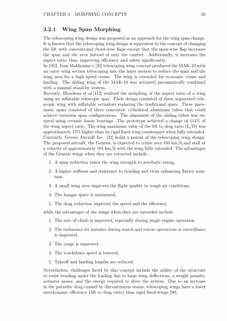
3.2.1 Wing Span MorphingThe telescoping wing design was proposed as an approach for the wing span change.It is known that the telescoping wing design is equivalent to the concept of changingthe lift with conventional chord-wise flaps except that the span-wise flap increasesthe span and the area instead of only the camber. Additionally, it increases theaspect ratio; thus, improving efficiency and safety significantly.In 1931, Ivan Makhonine’s [20] telescoping wing concept produced the MAK-10 withan outer wing section telescoping into the inner section to reduce the span and thewing area for a high speed cruise. The wing is extended for economic cruise andlanding. The sliding wing of the MAK-10 was actuated pneumatically combinedwith a manual stand-by system.Recently, Blondeau et al.[112] realized the morphing of the aspect ratio of a wingusing an inflatable telescopic spar. Their design consisted of three segmented tele-scopic wing with inflatable actuators replacing the traditional spars. These pneu-matic spars consisted of three concentric cylindrical aluminum tubes that couldachieve variation span configurations. The alignment of the sliding tubes was en-sured using ceramic linear bearings. The prototype achieved a change of 114% ofthe wing aspect ratio. The wing maximum value of the lift to drag ratio (L/D) wasapproximately 15% higher than its rigid fixed wing counterpart when fully extended.Currently, Gevers Aircraft Inc. [22] holds a patent of the telescoping wing design.The proposed aircraft, the Genesis, is expected to cruise over 450 km/h and stall ata velocity of approximately 101 km/h with the wing fully extended. The advantagesof the Genesis wings when they are retracted include:
1. A span reduction raises the wing strength to aerobatic rating,
2. A higher stiffness and resistance to bending and twist enhancing flutter resis-tant,
3. A small wing area improves the flight quality in rough air conditions,
4. The hangar space is minimized,
5. The drag reduction improves the speed and the efficiency,
while the advantages of the wings when they are extended include:
1. The rate of climb is improved, especially during single engine operation,
2. The endurance for instance during search and rescue operations or surveillanceis improved,
3. The range is improved,
4. The touchdown speed is lowered,
5. Takeoff and landing lengths are reduced.
Nevertheless, challenges faced by this concept include the ability of the structureto resist bending under the loading due to large wing deflections, a weight penalty,actuator issues, and the energy required to drive the system. Due to an increasein the parasitic drag caused by discontinuous seams, telescoping wings have a loweraerodynamic efficiency (lift to drag ratio) than rigid fixed-wings [90].

CHAPTER 3. MORPHING CONCEPTS 21
3.2.2 Inflatable Wing ConceptIn 1950s, Goodyear produced the first successful inflatable wings on their inflato-plane [45]. New materials address issues of leaking and deflation. Such wings canbe constructed of rigidizable fabric composites that harden, after deployment andexposure to ultra violet radiation, or of rugged woven materials to prevent dam-age. Thus, simply inflatable wings require constant pressurization to maintain theirshape, while inflatable/rigidizable wings harden into a persistent shape once inflated.The simply inflatable wings present a smooth surface compared to the rigidizablewings. This characteristic has a significant influence on the aerodynamic character-istics of the wing in terms of a higher lift and lower drag coefficients as it can beseen in Figure 3.5.The first use of inflatable wings in a UAV was applied to the Apteron vehicle thatwas developed in the 1970s by ILC Dover, Inc. Apteron had a 1.55 m wingspan, 373W engine, 3.18 kg gross weight and was remotely controlled via elevons mounted onthe trailing edge. It was successfull flight tested, but was never put into production[113].Recently, Simpson et al.[114] designed and constructed non-rigidizable inflatablewings to provide the roll control through the wing camber morphing. This is referredto as wing warping. Since the wings were non-rigid, it was possible to manipulatetheir shape to induce a roll moment. The wing design took advantage of the presenceof internal span-wise baffles (inflation cavities) to maintain the structural stiffnessat a lower internal pressure. The outer wing and internal baffles were constructedfrom high strength fibers such as Kevlar.Shape Memory Alloys (SMA), Electro-Active Polymers (EAP), and servo actuatedsystems represent good actuator candidates for inflatable wings. Cadogan et al.[115],for example, used SMA wires integrated to a multi-functional inflatable aerial vehi-cle. They actuated the aft end of the wing to achieve changes in section camber,leading to the aircraft roll control.Benefits of inflatable wings include wing morphing to alter aerodynamic character-istics in-flight, stowing when the wing is not in use to keep the vehicle size small,robustness, low mass, and low deployment time. Their applications include UAVssuch as High Altitude Long Endurance (HALE) vehicles. The wing planform canbe either full or partial span design, allowing a large design space and possible mis-sion adaptability. These wings are deployed to either provide new lifting surfacesor change the geometry of rigid lift surfaces. Their deployment increases both thespan and wing area, hence, the aspect ratio of the wing. This deployment can occurin a relatively short time depending on the size of the wing and on the type of theinflation system.

CHAPTER 3. MORPHING CONCEPTS 22
Figure 3.4 illustrates the deployment in-flight of NASA Dryden I2000 [56] inflat-able wing. Nitrogen gas pressurization of 1380-1725 kPa was applied to maintain asuitable wing strength and stiffness for the Dryden I2000.Apart from the use as a stand alone aerodynamic surface on a morphing UAV, theinflatable system can also be used as an aspect ratio increasing device on a largeraircraft to enable a more radical change in the wing configuration. This techniqueimproves the system efficiency across changing flight regimes, allowing the transitionfrom a high speed target approach to a low speed loitering [47].
Figure 3.4: In-flight deployment of I2000 inflatable Wing [46].
Figure 3.5: Aerodynamic coefficients of an inflatable wing [12].
3.2.3 Sweep Angle VariationThe concept of variable sweep started during World War II with the variable wingMesserschmitt P.1101 and was implemented by the US army on the Bell X-5 [21].In this design, the aerodynamic forces on the wing are carried by a complex andheavy pivoting mechanism. The concept attempts in the supersonic range to havea small compact wing for high speed flights and one with larger area and span fortakeoff climb and cruising. The design allows an aircraft to vary its aspect ratio andthickness to chord ratio (fineness ratio) to optimize the configuration for differentflight Mach numbers [25].
CHAPTER 3. MORPHING CONCEPTS 23
This concept may be implemented using one of the three approaches including:
1. The whole wing outboard of fuselage moves,
2. The outer part of the wings moves,
3. The wings, when swept back are integrated with the tailplane to form a deltasurface.
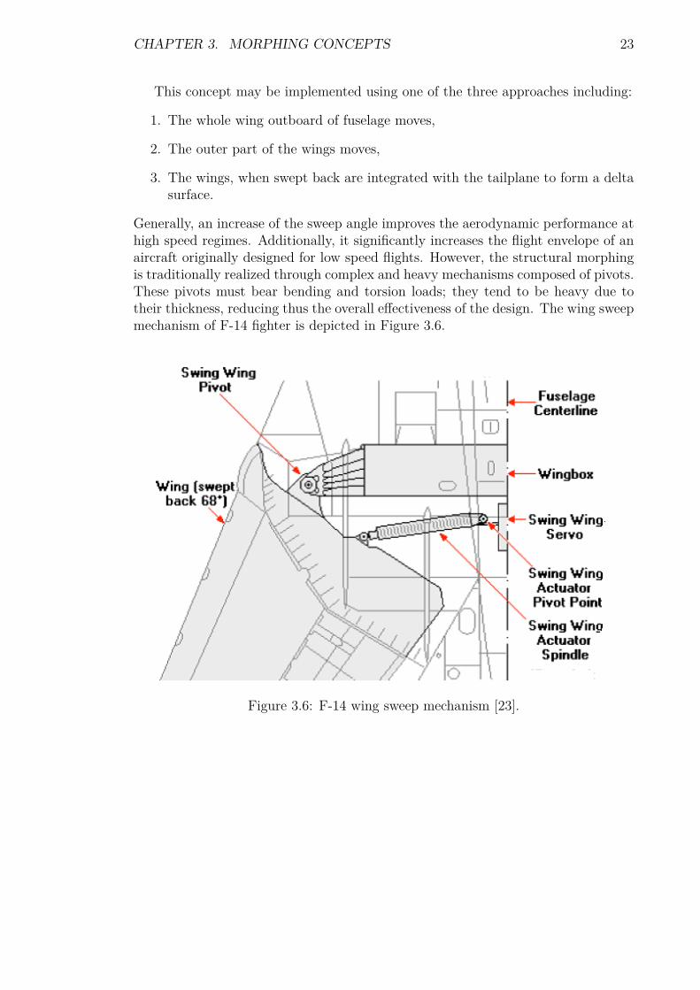
Generally, an increase of the sweep angle improves the aerodynamic performance athigh speed regimes. Additionally, it significantly increases the flight envelope of anaircraft originally designed for low speed flights. However, the structural morphingis traditionally realized through complex and heavy mechanisms composed of pivots.These pivots must bear bending and torsion loads; they tend to be heavy due totheir thickness, reducing thus the overall effectiveness of the design. The wing sweepmechanism of F-14 fighter is depicted in Figure 3.6.
Figure 3.6: F-14 wing sweep mechanism [23].
CHAPTER 3. MORPHING CONCEPTS 24
The characteristics of variable sweep concept include [24]:
1. Delay in the drag rise. Thus, the subsonic speed and high altitude cruisespeeds are increased.
2. Lower subsonic drag. Consequently, supersonic speeds can be reached withoutexcessively low thickness ratios or high wing loading.
3. Lower lift slope. This implies a higher approach and cruise attitude, and areduction in gust sensitiveness at high speed.
Nevertheless, the variable sweep concept involves difficulties including structuralthickness, significantly high wing loadings and transonic and supersonic trim diffi-culties [19]. To eliminate penalties associated with this concept, the oblique wingapproach was developed. The oblique wing flies supersonically with one wing sweptforward and the other swept backward. At low speeds, the wing changes to anunswept design for a better subsonic efficiency. It is known to have a lower super-sonic wave drag than conventionally designed symmetrically swept wings. Addition-ally, when flying at low speeds, the unswept wing has a higher efficiency than sweptwings. An oblique wing can vary the wing sweep with a single pivot that is primar-ily loaded in tension, trading the aspect ratio for the fineness ratio by sweeping onewing tip forward and the other wing tip backward. Furthermore, the asymmetricsweep can increase the fineness ratio of the wing more significantly than a symmetricsweep design [25].NextGen Aeronautics [59] developed UAVs based on scissors mechanism resulting ina variable sweep falling into the range of 15 to 35 degrees in-flight. NextGen’s UAVis reviewed in section 3.5.Alternatively, Friswell et al.[27] successfully demonstrated the use of unsymmetricallaminated composites to realize a variable sweep wing for morphing UAV appli-cations. Their numeric analysis identified the bifurcation point referred to as asnapping point at which the geometry changes. This confirms the possibility ofeliminating mechanical joints to obtain different geometries. In their design, thewing spars are made of bi-stable composites. When a bending moment is applied onthe spar, it causes the spar to snap to a second stable position around the bifurcationpoint which acts as a hinge. Therefore, the application of multistable compositessimplify the complex mechanical systems required to modify the geometry of con-ventional wings [44]. However, the use of bi-stable composite materials may sufferfrom fatigue at the bifurcation point. Furthermore, the compliance of the wing skinmay interfere with the snapping motion [111]. Multi-stable composite materials arereviewed in Chapter 5.
3.3 Out-Of-Plane TransformationsAn alternative approach to modifying the aerodynamic characteristics of a wing isto alter the wing out of its original plane. Several researches [83, 30, 111] haveshown the potential of smart materials to accomplish the out-of-plane alternation ofa morphing wing through camber change. This section presents the wing camber,chord, and twist controls.

CHAPTER 3. MORPHING CONCEPTS 25
3.3.1 Camber And Chord ControlIn the camber control approach, the adaptive airfoil can alter its camber to ob-tain the desired lift. This eliminates the need for conventional control surfaces.Experimental and computational results show a high promise for variable cambergeometries [31]. Camber change is performed either by the reconfiguration of thewing internal structure or the alternation of the wing skin. However, variable geom-etry airfoils such as the one developed for the Mission Adaptive Wing (MAW) [48]are complex structurally and consequently heavy and maintenance intensive.Recently, Diaconu et al.[49] intensively investigated the use of bi-stable or multi-stable structures as a morphing approach for the airfoil chord and camber changes.The bi-stability behaviour of the composite is the result of the simultaneous effects ofresidual stress resulting from cooling and the non-linear deflections in the structure[50]. In Diaconu’s design, such a bi-stable composite plate was embedded chord-wiseand vertically in the airfoil cross section. This plate snapped from one stable positionto another under moments applied alternatively by actuators on the edges of thelaminate. Thus, the chord-wise composite member controlled the airfoil camber,while the vertical element altered its chord length.Furthermore, Ursache et al.[52] demonstrated that by using structures that are act-ing in the post-buckling regime, it is possible to obtain significant changes in shapewith very modest changes in the applied load. Thus, by making use of non-linearstructural responses, camber control of deformable airfoils can be achieved by us-ing a carefully designed pre-loaded internal spinal structure. Such a structure isexpected to move through the desired shape changes under the control of a singleactuator. This actuator will deliver aerodynamic characteristics that match a set ofpre-specified target shapes and also give improved aero-elastic properties.Sofla et al.[132] developed a series of SMA-actuated flexural structures which couldbe used to deform wing sections. Their actuated structures were based on a conceptcalled antagonistic flexural unit cell (AFC). In this concept, a pair of one-way SMAactuators are placed at either side of a highly flexible unit core structure with largein-plane stiffness. The contraction of one SMA actuator upon heating results in theextension of the opposing SMA actuator mechanically. The contraction by heatingof the now-extended actuator, later in the cycle, reverses the actuation.High authority shape morphing beams can be made by the linear replication ofthe AFCs. Such actuated beams can be used to make reconfigurable wing boxesfor shape morphing wing structures. Although the slow cooling rate of the SMAactuation is not appropriate for the flight control applications, the achievable aero-dynamic changes are still suitable for in-flight mission adaptation of the wing. TheAFC based actuated structures are attractive for wing morphing applications be-cause the distributed SMA actuators carry aerodynamic loads and therefore reducethe weight penalty. Additionally, the new wing shapes after the cooling of each SMAactuator are retained without requiring power. This can eventually result in savingfuel and increasing the aircraft endurance [111].

CHAPTER 3. MORPHING CONCEPTS 26
Figure 3.7 illustrates a wing section prototype that is capable of undergoingcamber changes when actuated by antagonistic SMA actuators.
Figure 3.7: Chord-wise bending achieved by the heating of SMA strips in an antag-onistic design. (a) Un-morphed and (b) morphed [133].
3.3.2 Wing Twist ControlIn morphing via variable twist, the wing is configured to optimize the twist angle toobtain low drag and high lift aerodynamic characteristics. Sofla et al.[111] report thegradual changes of the airfoil chamber along the span as a method to create a con-trollable twisting of the wing. In their design, an antagonistic wing was prototypedusing shape memory alloy (SMA) actuators. An antagonistic structure is based ona pair of one-way SMA actuators as described in the previous section. Thus, thewing undergoes twisting by the asymmetric actuation of its SMA actuators.In an alternative approach, Mujahid et al.[116] controlled the roll of a mini UAVby twisting its flexible wing. In their design, torque rods ran spanwise. These rodswere rotated separately by two servo-motors mounted in the fuselage. Commandinga deflection of the servo induces the rods to rotate by acting against the wing leadingedge. Their results for flight characteristics for the roll and spinning showed thatthe vehicle was easier to fly using morphing instead of the conventional rudder aslateral directional effector.

CHAPTER 3. MORPHING CONCEPTS 27
Figure 3.8 presents the twisting of a wing section using antagonistic SMA actuation.
Figure 3.8: Twisting of a wing section achieved by antagonistic SMA actuation. (a)The left rib is flexed downward and right rib upward. (b) The left rib is actuatedupward and the right one downward [133].
Figure 3.9 illustrates the nominal wing and the morphed wing when each servo-motoris commanded to its equal but opposite value.
Figure 3.9: Nominal wing (left) and morphed wing (right) [116].
Moreover, adaptive aero-elastic structures offer potential solutions to achieve wingmorphing through out-of-plane transformation. This approach uses the aerodynamicforces acting upon the wing to provide the necessary forces and moments to bendand twist the wing. These structures are reviewed in Chapter 5.

CHAPTER 3. MORPHING CONCEPTS 28
3.4 Airfoil Profile AdjustmentsAn airfoil significantly influences the aerodynamic characteristics of any aircraft. Bytailoring the shape of the airfoil, the aircraft efficiency can be modified by tuning anoptimum airfoil configuration. Thus, if an airfoil section can be changed accordinglywith the shift of flight conditions, benefits may result that include the improvementsof the Mach number, aerodynamic efficiency, aerodynamic performances such asthe range, endurance, and the expansion of the flight envelope. The airfoil profileadjustments to alter the aerodynamic characteristics of the wing, as described inFigure 3.3, reshap the wing profile with no significant change of its camber. Austinel at.[117] developed a theoretical method which was experimentally validated. Theirpurpose was to control the static shape of flexible structures by employing internaltranslational actuators. In their design, 14 linear actuators were attached diagonallyto form a wing rib structure as depicted in Figure 3.10. The diagonal elements aretranslational actuators that expand and contract to deform the airfoil. A prototypeof the adaptive rib with the actuators was constructed to demonstrate the shape-control concept.
Figure 3.10: Airfoil profile control [117].
Dong el at.[118] designed and manufactured a changeable airfoil model using SMAsprings between the wing skin and its supporting wing-box. Thus, by changing theconstraint condition of the skins, they can achieve large deformation without over-stepping their strain allowance. Shape memory alloy springs with the help of stopstructures were used to actuate accurately certain points on the skins to approachthe target airfoil. The wing-box consisted of rigid steel ribs and spars. The coveringskin was allowed to slide over a cushion at the leading edge spar as illustrated byFigure 3.11. Cushions were used in order to avoid dislocation between the skinswhich were level with that of the tailing edge box. The resizing of the SMA springlength upon heating and cooling could alter the wing thickness.

CHAPTER 3. MORPHING CONCEPTS 29
Figure 3.11: Position of the wing skins [118].
Table 3.2 summarizes actuation and skin types associated to a typical wing morph-ing.
Table 3.2: Morphing concepts, actuation and skin types.

CHAPTER 3. MORPHING CONCEPTS 30
3.5 Morphing UAVsSeveral researchers [111, 114, 115, 118] have investigated, designed and prototypedmorphing UAVs. The two most successfull flight-tested vehicles are described in thissection.A large scale of wing morphing is achieved using either rigid mechanisms or smartmaterials embedded in the wing structures. Rigid mechanisms were used to achievelarge shape changes in DARPA [2] morphing program under which NextGen Aero-nautics and Lockheed Martin built full-scale wind-tunnel models as well as thesubscale flying models. Lockheed’s morphing concept is performed by folding thewings upwards and inwards to reduce its area and increase the sweep for a high-speed dash. In contrast, NextGen uses a movable scissors structure, covered witha flexible silicone skin reinforced with metal mesh, enabling the wing to reduce inarea as it is swept back.As a result of their intensive investigations, the first in-flight demonstration of ashape changing, or morphing wing was performed by NextGen with the UAV namedMFX-1 [59]. The geometry change was implemented using an internal electro-mechanical actuation system. Approximately 200% change in aspect ratio, 70%change in area, 40% change in span, while independently controlling the sweep andarea, and a wing sweep varying from 15 degrees to 35 degrees were demonstratedat various flight speeds around 50 m/s [96]. The model has a 3 meters semi-spanwhen fully extended; but it reduces to 2.2 meters when the wing is retracted for highspeed flights [61]. This successful test represents the first step in the developmentof a morphing UAV whose wing geometry can be rapidly and reversibly changed tooptimize the aircraft for dramatically different flight conditions.Following their previous success, NextGen completed the first autonomous flights ofa morphing unmanned aerial vehicle named MFX-2 [59], a scaled version of MFX-1weighting 135 kg and powered by twin-jet engines. The MFX-2 is capable of inde-pendently varying the wing area and sweep. The flight tests were the demonstrationsof the morphing technology for a Hunter-Killer (Predator B) UAV, combining theloiter endurance of a surveillance platform with the high-speed dash capability of anattack aircraft. MFX-2 has the ability to create substantial in-plane shape changesand a surface area reduction to transform the wing from an efficient, high-aspect-ratio loiter shape to an efficient, swept, reduced-wing-area transonic, low altitudedash shape [62]. Its wing has flexible, stretchable skin panels attached to an ar-ticulated lattice structure with actuators in the joints. Thus, morphing is achievedthrough the adjustable framework to allow in-plane reconfiguration of highly flexibleskins and internal components that create wing area and span changes, includingchanging leading edge sweep to control aerodynamic drag [62].The variable geometry wing has the ability to move between five different wingplanforms as illustrated in Figure 3.12. An increase of 36% in the aerodynamicefficiency from the cruise flight to the loiter configuration is noticeable from Figure3.12, while the wing surface increases 51% from the cruise regime to dash maneuverconfiguration. The wing mechanism is described in Chapter 5.

CHAPTER 3. MORPHING CONCEPTS 31
Figure 3.12: NextGen’s morphing wing planform configurations [62].
Lockheed’s morphing UAV was designed to investigate interactions between aero-dynamics and structures (an aero-elasticity analysis and testing research and devel-opment project). This design uses wing folding in several positions to reduce thewetted area and change the sweep at critical points in the mission [62]. The flighttests demonstrate long loiter time and high dash speed in a single shape-changingaircraft. The hinges of the folding wing are covered by flexible silicone skins, andsmall flaps on the inboard leading edges close the gaps between the inward-foldedwing and the fuselage. This flap is the first surface to be powered by a thermo-polymer actuator which can fit inside the wing thin leading edge. The model has a2.9 meters semi-span when unfolded for loiter and a 1.8 meters when folded for highspeed flights [61].

CHAPTER 3. MORPHING CONCEPTS 32
Figure 3.13 shows the folding wing concept with wings fully extended and re-tracted. The wing mechanism is described in Chapter 5.
Figure 3.13: Lockheed’s folding wing concept [62].

Chapter 4
Actuators And Sensors
This Chapter presents sensors and actuators. Additionally, it reviews the commonsmart materials. Smart materials require power supply or temperature regulationto induce deformations and maintain a stable state.
4.1 Fiber Optic SensorsIn 1990s, Dunphy et al.[42] identified number of benefits in combining optical fibersand composites. Compared with other sensing methods, optical fibers provide sev-eral compelling advantages. One of the most important benefit is their immunityto electro-magnetic interference. This eliminates the need for the costly and heavyshielding normally required to minimize electrical noise picked up when using electri-cally active sensors. Additionally, fiber optic sensors provide a high bandwidth, highsensitivity, and high dynamic range measurement capability. Additional advantagesof this technology include fatigue, corrosion resistance, and the inherent strength ofglass fibers [40]. These features enable fiber optic sensors to perform efficiently inextremely hostile environments of high temperatures, erratic vibrations, and shockloadings. The use of optical fiber technology with smart structures enables both therealization of multiplexed arrays of fiber sensors inter-connected by other fibers andthe implementation of distributed sensors. Thus, Wood [43] mentioned the fiberBragg grating sensor as an example in spacecraft application.Recently, Yin et al.[40] distinguishes two basic classes of fiber optic sensors referredto as extrinsic optic sensors and intrinsic sensors. They are embedded into or at-tached to materials during the manufacturing process to enhance process controlsystems, augment the non-destructive evaluation once the parts have been made.Additionally, they form health and damage assessment systems once the parts havebeen assembled into the structures, and enhance control systems.
33

CHAPTER 4. ACTUATORS AND SENSORS 34
A basic fiber optic smart structure system is depicted by Figure 4.1.
Figure 4.1: Basic fiber optic smart structure system [40].
In the figure above, fiber optic smart structure systems consist of optical fiber sensorsembedded or attached to parts. These parts sense environmental effects that aremultiplexed and directed down. The effects are then sent through an optical orelectronic signal processor. The signal processor in turn feeds the information to acontrol system that may or may not act on the information via a fiber link to anactuator.
4.2 Smart MaterialsAdvances in material technology have enabled the development of devices which canserve as both sensors and actuators. By integrating these devices into a structuretogether with a controller, the material becomes “Smart”. In fact, the materialsthemselves are not “smart” since they passively react to an input rather than mak-ing decisions. By incorporating actuators within a composite structure to make thestructure bend, the concept of shape control or morphing can be implemented. Asmart structure should possess the ability to sense its internal and external environ-ment. It should then be able to communicate the sensory signals via appropriatepathways (Figure 4.1) to one or several signal processing and control modules, wherethe information is analyzed and appropriate actions are decided. If necessary, thedecisions must be conveyed to actuators incorporated within the structure, whichrespond by altering its characteristics such as the shape, size, stiffness, position, ornatural frequency [41].

CHAPTER 4. ACTUATORS AND SENSORS 35
The actuators incorporated in the composite wing structure may induce the wingtwist, camber shaping and control surface deformations. Additionally, these materi-als may produce structures with variable stiffness. The aerodynamic efficiency of acontrol surface may also be controlled and improved by changing the flow conditionsover the lifting surface. The expected benefits from such concepts include a reduceddrag over a broad range of flight conditions, increased payload, greater range, im-proved aerodynamic performance, and improved stealth characteristics [35].It is common to classify smart materials as:
(a) Intrinsically adaptive materials. This category includes Shape MemoryAlloys (SMA) and Shape Memory Polymers (SMP). When stimulated, thesematerials are subjected to transformations in their molecular or microscopicstructures. These transformations induce changes in material mechanical prop-erties.
(b) Active materials. This class includes electro-active polymers (EAP), Piezo-electric ceramics (PZT), and magnetostrictive materials. They act as trans-ducers converting electrical, magnetic, or thermal energy into a mechanicalenergy.
The material choice depends on the specific morphing purpose. If the morphing isdedicated to flight control, the morphing system should exhibit [55]:
1. Relatively fast dynamic,
2. Capability to operate over a wide range of flight conditions,
3. High reliability,
4. Capability of repetitive actuation,
5. Robustness against uncertainties and disturbances such as gust loads,
6. Low power consumption.
Therefore, the ideal material should respond quickly to the external stimuli, becapable of large and recoverable free strains, transform effectively the input energyinto mechanical energy. Additionally, it should not be affected by fatigue issues.The use of smart materials simplifies mechanical systems and thus reduces operat-ing costs. Moreover, it significantly expands the functionality or operating range sothat a single system can have multiple uses with a substantial adaption to differentconditions. Furthermore, these materials increase the resilience of the system by im-proving diagnostics, addressing unforeseen problems, and enabling new capabilities.

CHAPTER 4. ACTUATORS AND SENSORS 36
Table 4.1 reports the main characteristics of the most common smart materi-als in terms of maximum free strain, maximum stress, deformation energy density,efficiency, and relative speed of response.
Table 4.1: Most common smart materials [54].
From the table above, SMAs and SMPs can undergo large free strains1 and exhibitlarge blocking forces2. Nevertheless, they have a slow response and a limited effi-ciency. PZT and single crystal Piezo-ceramics exhibit a much lower free strain butthey are capable of producing quite high blocking forces, and sensibly more efficient.
1Free displacement or free strain refers to the maximum displacement an actuator can developwhen there is no restraint against it.
2Blocking force refers to the maximum force an actuator can develop when it is reacting againsta fixed constraint.

CHAPTER 4. ACTUATORS AND SENSORS 37
Electro-active polymers exhibit good properties, although they can produce lowblocking stress [55]. Whilst hydraulic actuators can develop large displacements,they have a low blocking force. Piezo-electric stack actuators can develop largeforces but they cannot induce large displacements.Bending type actuators provide high displacements of the order of 1mm with lowblocking force about 0.5N . The stack actuators provide low displacements of theorder of 1µm with high blocking force appropriately 1kN . These two actuator typesrepresent the extreme ends of the current Piezo-electric actuation technology. In theintermediate range, there is a deficiency of the actuator designs that would providehigh displacement with high blocking force in the frequency range of few kilohertz[66].
4.3 Shape Memory AlloysModern morphing research intends to identify, explore and prototype new materialsor mechanisms for active deformations of a high performance vehicle wings with theultimate goal of a fully integrated adaptive wing structure for shape and maneuvercontrol, performance improvements, stability augmentation, gust load alleviation,and health and usage monitoring [36]. Therefore, in the new approach to morph awing efficiently, scientists and engineers envision a wing that will sense its environ-ment and adapt its shape to perform optimally in a wide range of flight conditions[37]. Such a wing will spread out on command using shape memory metal alloys orother novel smart materials. It is expected that the material of the wing itself willbend to create the new shape.Shape memory alloys (SMAs) are metallic alloys which undergo solid-to-solid phasetransformations induced by appropriate temperature and/or stress changes. Duringthese changes, the materials can recover permanent strains. Such alloys includeNiTi, NiTiCu, and CuAlNi [53]. They have the unusual property of snapping backto their original shape with a high force when a certain amount of heat is applied.Therefore, any shape can be modeled into the alloy as its original shape. Thesealloys are effective for low frequency applications. They have been utilized to realizethe hingeless control surfaces in the Smart Wing program of DARPA [48].The shape memory materials exhibit some novel performances including sensoring(thermal, stress or field), large stroke actuation, high damping, adaptive responses,shape memory, and super-elasticity capability which can be utilized in various en-gineering approaches to smart systems.

CHAPTER 4. ACTUATORS AND SENSORS 38
4.4 Piezo-Electric MaterialsPiezo-electric materials are able to produce an electrical response when mechanicallystressed and inversely a high precision motion can be obtained with the applicationof an electrical current. Developments in adaptive composite structures, by incorpo-rating integrated Piezo-electric elements, open the possibility to adaptively modifythe behavior of a structure. This offers potential benefits in a wide range of engineer-ing applications including wing morphing, vibration damping, precision positioning,and buckling control. Piezo-electric materials are the most popular because theirbandwidth covers most of the important aero-elastic modes [36].
4.4.1 Active Fiber CompositesActive fiber composites (AFC) constituted of unidirectional Piezo-electric ceramicfibers sandwiched between two electrodes and embedded in a polymer matrix presentmajor advantages over conventional Piezo-electric materials like ceramics and poly-mers. AFCs provide a novel method for large scale actuation and sensing in activestructures. They have demonstrated distinct advantages over current monolithicPiezo-ceramic actuators. These advantages include [36]:
1. Higher planar actuation strains,
2. A directional actuation or tailorable orthotropic actuation,
3. A robustness to damage,
4. A conformability to curved surfaces,
5. A potential for large area distributed actuation/sensing systems.
4.4.2 Macro Fiber CompositeThe Macro Fiber Composite (MFC) proposed by NASA [39] is a material expectedto act like muscles and nerves. It can be attached to a structure to bend it, reduce thevibrations and monitor the forces. The composite material is composed of ceramicfibers that can bend when a current is applied to them. By applying voltage to theMFC, the ceramic fibers change shape to expand or contract and turn the resultingforce into a bending or twisting action on the material. Likewise, voltage is generatedin proportion to the force applied to the MFC material. The material also generatesa current when it is vibrated or flexed.

Chapter 5
Structure Solutions
This Chapter introduces the factors that need to be considered when designing amorphing structure. Additionally, it reviews the structural solutions to achieve themorphing of a planform. The two last sections of this Chapter discuss the limitationsset by the square-cube law on the use of materials in term of scalability and addressthe control issues of morphing vehicles.
5.1 Design Aspects of Morphing StructuresAs mentioned earlier, the wing is mainly responsible for the aerodynamic loadsacting on the aircraft. Hence, most of research on morphing aircraft investigatesthe possibility of effectively changing the wing geometry. The design of a morphingaircraft is a multidisciplinary and interactive process since the idea is to design astructure that is capable of withstanding predetermined loads and to change itsshape in order to bear random loads during operation.McGowan [12] mentioned design key factors including weight as a primary require-ment, followed by functionality since each mission and therefore the associated ve-hicle has different requirements and constraints. Figure 5.1 illustrates the smartmorphing design concept which is the interaction of conflicting design perspectivesincluding flight control, aero-elasticity and power requirements. For instance, theengines supplying the system power are expected to be efficient at low and highspeed operations at any altitude. The actuator performance power and actuatorforce capability are essential to design success. The size, weight and volume of theactuators are important factors [62].
39

CHAPTER 5. STRUCTURE SOLUTIONS 40
Figure 5.1: Morphing smart design concept [98].
Morphing can be implemented using motors or complex mechanisms distributedthrough the wing. However, to reduce the complexity of the structure, the actuationsystem consisting of active materials should be embedded in the structure so thatno clear distinction can be made between the structure and actuation systems.Therefore, what is envisaged to produce and carry the loads is also capable tochange its own shape or a limited part of it. Thus, design considerations shouldinclude [78]:
(a) Aerodynamic vs. structural shaping: It ranges from pure aerodynamics(synthetic jets) to the heavily structural conforming flap.
(b) Static vs. dynamic: This will determine the working “bandwidth” of themorphing structure by considering how fast is the shape change required andhow often it needs to be changed. Thus, the speed and the frequency at whichthe shape change occurs are significant design parameters. Slow, quasi-staticchanges may be sufficient for some missions; rapid changes to increase aircraftmaneuverability will make future morphing aircraft even more capable [32].
(c) Small vs. large deformation: This should clarify how several degrees equiv-alent rotation and strain levels are induced by the morphing. Small and largemorphing have been discussed in Chapter 3.

CHAPTER 5. STRUCTURE SOLUTIONS 41
It is obvious that prior to morphing there is no actuation and the wing exhibitsa high stiffness state. However, during morphing, a minimal actuation is requiredand the wing is in a low stiffness state with changes in aerodynamic loads andactuation forces. Following the morphing, the system returns to its initial conditionsof actuation and stiffness. The structural integrity of the wing must be preservedunder all circumstances.Depending on the expected performance, the following elements should be consid-ered [98]:
(a) Extent of the shape change,
(b) Type of actuation,
(c) External work,
(d) Evaluation of deformation energy involved,
(e) Speed of actuation,
(f) Evaluation of power required,
(g) Level of reliability needed,
(h) Actuation occurrence,
(i) Necessity to operate in different conditions.
Moreover, optimization investigations can be performed for drag reduction [29, 99,100, 101] and to minimize the power needed for actuation [17].
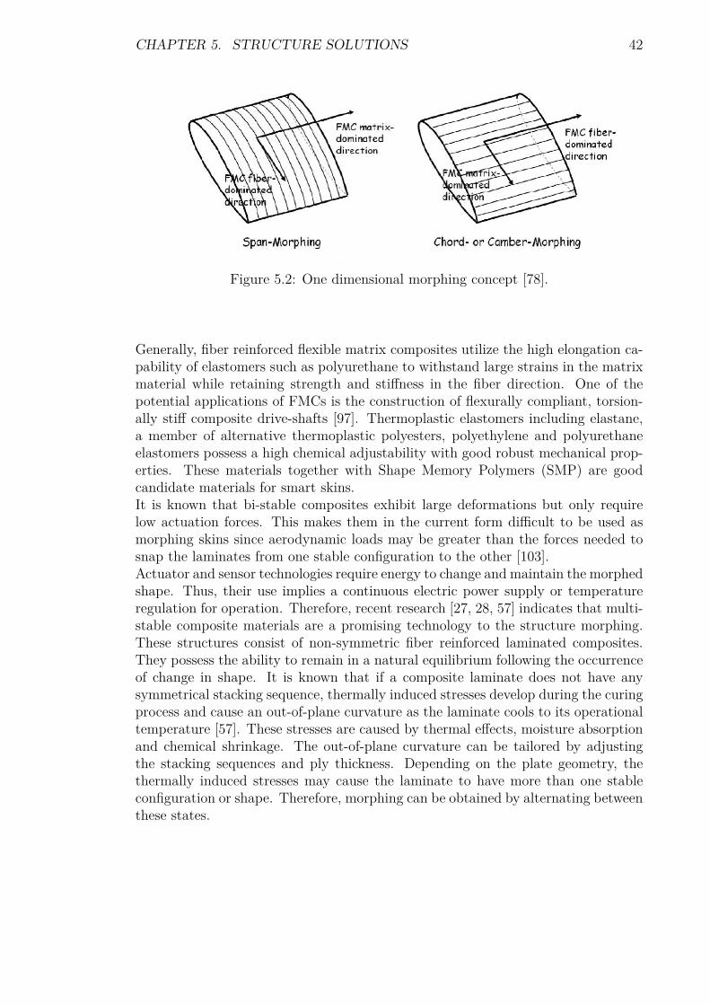
5.2 Multi-Stable Composite MaterialsTo minimize the structural weight and the complexity of a flying vehicle, compositematerials provide a promising solution. Generally, composite materials present highspecific strength and stiffness ratios. The high degree of design flexibility of fiberreinforced composites has increased their applications in aerospace structures. Thisis due to their superior performance compared to metals. It is known that theproperties of a composite depend on factors including the choice of the constituentmaterials, the method of combining them, and the process of fabrication. Thisdesign flexibility, though complex, enables the designer to tailor the material toobtain a desired structural response. Subsequently, to obtain a span-wise morphingwing using flexible matrix composite (FMC), it is common to orientate the fibersalong the chord, with the matrix direction aligned along the span as depicted inFigure 5.2. This configuration produces large strains at low actuation force and thefibers provide reinforcement and out-of-plane load carrying ability. In contract, forchord or camber changes, the fibers are orientated along the span while the matrixdirection is aligned with the chord. This direction may undergo large strains at lowactuation force. Thus, the fibers aligned with the span provide reinforcement andout-of-plane load carrying ability [78].However, these basic orientations are weak to resist shear loading. Therefore, thestacking sequences of the laminate should consider orientations including 45 degrees.
CHAPTER 5. STRUCTURE SOLUTIONS 42
Figure 5.2: One dimensional morphing concept [78].
Generally, fiber reinforced flexible matrix composites utilize the high elongation ca-pability of elastomers such as polyurethane to withstand large strains in the matrixmaterial while retaining strength and stiffness in the fiber direction. One of thepotential applications of FMCs is the construction of flexurally compliant, torsion-ally stiff composite drive-shafts [97]. Thermoplastic elastomers including elastane,a member of alternative thermoplastic polyesters, polyethylene and polyurethaneelastomers possess a high chemical adjustability with good robust mechanical prop-erties. These materials together with Shape Memory Polymers (SMP) are goodcandidate materials for smart skins.It is known that bi-stable composites exhibit large deformations but only requirelow actuation forces. This makes them in the current form difficult to be used asmorphing skins since aerodynamic loads may be greater than the forces needed tosnap the laminates from one stable configuration to the other [103].Actuator and sensor technologies require energy to change and maintain the morphedshape. Thus, their use implies a continuous electric power supply or temperatureregulation for operation. Therefore, recent research [27, 28, 57] indicates that multi-stable composite materials are a promising technology to the structure morphing.These structures consist of non-symmetric fiber reinforced laminated composites.They possess the ability to remain in a natural equilibrium following the occurrenceof change in shape. It is known that if a composite laminate does not have anysymmetrical stacking sequence, thermally induced stresses develop during the curingprocess and cause an out-of-plane curvature as the laminate cools to its operationaltemperature [57]. These stresses are caused by thermal effects, moisture absorptionand chemical shrinkage. The out-of-plane curvature can be tailored by adjustingthe stacking sequences and ply thickness. Depending on the plate geometry, thethermally induced stresses may cause the laminate to have more than one stableconfiguration or shape. Therefore, morphing can be obtained by alternating betweenthese states.

CHAPTER 5. STRUCTURE SOLUTIONS 43
The main advantage of using these structures is that they will maintain one of thestable shapes with the need of no force holding them in that position. This meansthat power is required only to transform the structure from one stable configurationto another. Hence, they can carry loads in both states as long as they do not reachthe critical snap-through load. Figure 5.3 illustrates examples of bi-stable materials.
Figure 5.3: Bi-stable composite materials [88].
If composite materials with multiple stable states are to be used for morphing air-craft, adequate actuation system must be defined so that these materials may snapfrom one stable state to another. Thus, in his PhD dissertation, Schultz [119] usedPiezo-electric patches (Macro Fibre Composite (MFC)) bonded to the surface of thelaminate to induce snap-through with a shear force. Schultz successfully produceda morphing laminate based on the MFC actuator and obtained good predictions ofthe snap-through loads for a patch bonded in the middle of the plate. Additionally,Schultz et al.[120] discussed the concept of using a Piezo-ceramic actuator bondedto a side of a two-layer asymmetric cross-ply laminate to provide the moments nec-essary to snap the laminate from one stable equilibrium shape to another. Theirexperimentally measured stable shapes of the laminate-actuator combination werepredicted very well using a model, and the predicted actuation voltage needed toinitiate the snap-through behavior was reasonably close to the experimental value.Schultz et al model is reviewed in Chapter 6. Furthermore, Dano and Hyer [121] butalso Hufenbach et al.[122] used shape memory alloy (SMA) wires to apply a bend-ing moment to a plate as a demonstration of the snapping-through of multi-stablecomposite materials for morphing applications. These wires require to be heated intheir operating ranges.
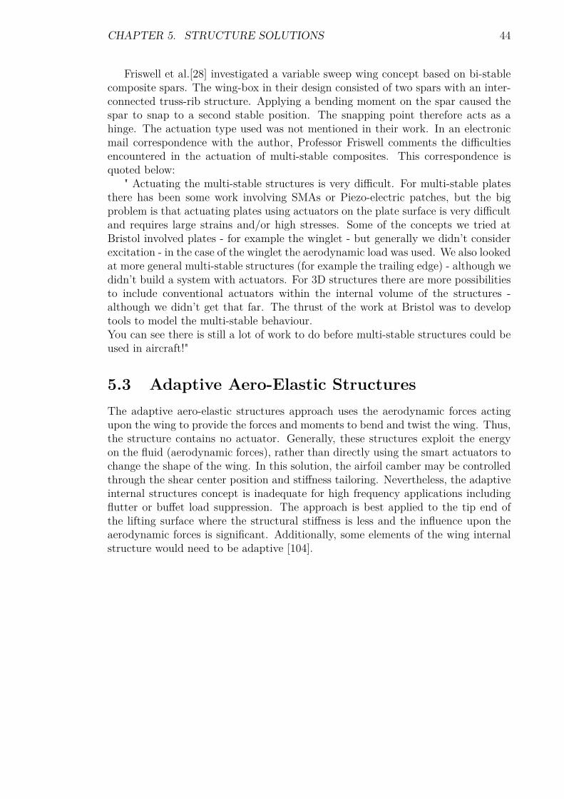
CHAPTER 5. STRUCTURE SOLUTIONS 44
Friswell et al.[28] investigated a variable sweep wing concept based on bi-stablecomposite spars. The wing-box in their design consisted of two spars with an inter-connected truss-rib structure. Applying a bending moment on the spar caused thespar to snap to a second stable position. The snapping point therefore acts as ahinge. The actuation type used was not mentioned in their work. In an electronicmail correspondence with the author, Professor Friswell comments the difficultiesencountered in the actuation of multi-stable composites. This correspondence isquoted below:
" Actuating the multi-stable structures is very difficult. For multi-stable platesthere has been some work involving SMAs or Piezo-electric patches, but the bigproblem is that actuating plates using actuators on the plate surface is very difficultand requires large strains and/or high stresses. Some of the concepts we tried atBristol involved plates - for example the winglet - but generally we didn’t considerexcitation - in the case of the winglet the aerodynamic load was used. We also lookedat more general multi-stable structures (for example the trailing edge) - although wedidn’t build a system with actuators. For 3D structures there are more possibilitiesto include conventional actuators within the internal volume of the structures -although we didn’t get that far. The thrust of the work at Bristol was to developtools to model the multi-stable behaviour.You can see there is still a lot of work to do before multi-stable structures could beused in aircraft!"
5.3 Adaptive Aero-Elastic StructuresThe adaptive aero-elastic structures approach uses the aerodynamic forces actingupon the wing to provide the forces and moments to bend and twist the wing. Thus,the structure contains no actuator. Generally, these structures exploit the energyon the fluid (aerodynamic forces), rather than directly using the smart actuators tochange the shape of the wing. In this solution, the airfoil camber may be controlledthrough the shear center position and stiffness tailoring. Nevertheless, the adaptiveinternal structures concept is inadequate for high frequency applications includingflutter or buffet load suppression. The approach is best applied to the tip end ofthe lifting surface where the structural stiffness is less and the influence upon theaerodynamic forces is significant. Additionally, some elements of the wing internalstructure would need to be adaptive [104].
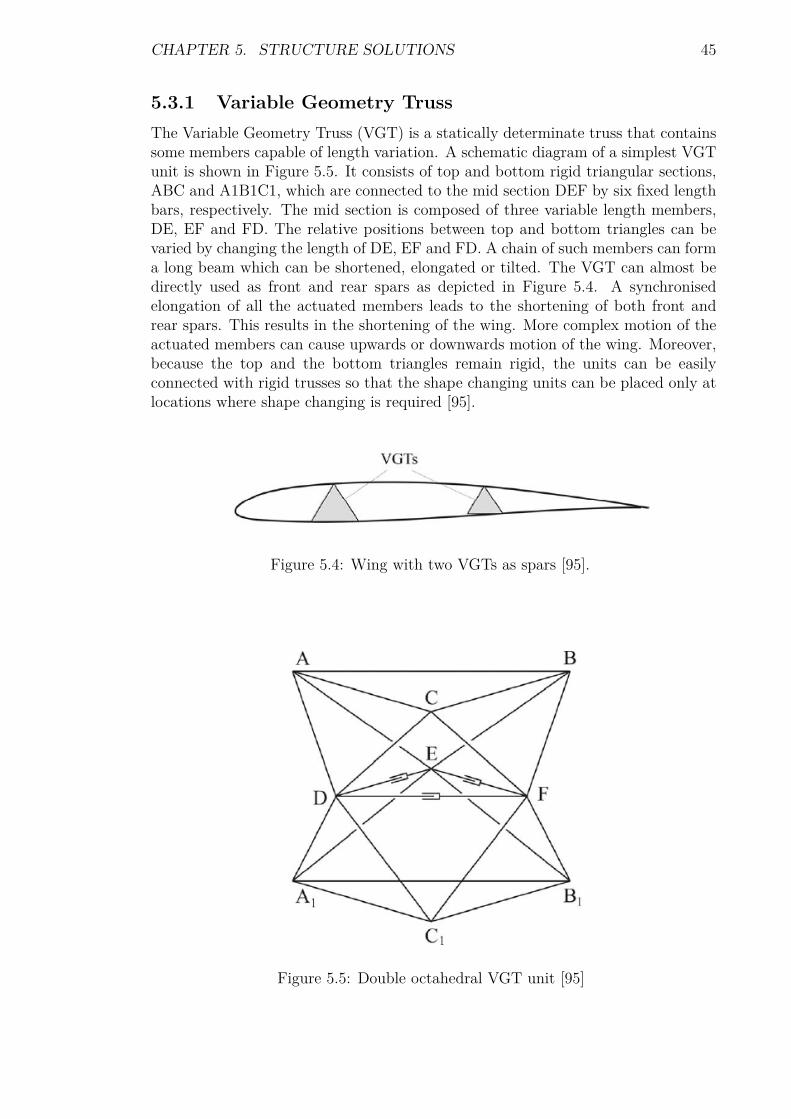
CHAPTER 5. STRUCTURE SOLUTIONS 45
5.3.1 Variable Geometry TrussThe Variable Geometry Truss (VGT) is a statically determinate truss that containssome members capable of length variation. A schematic diagram of a simplest VGTunit is shown in Figure 5.5. It consists of top and bottom rigid triangular sections,ABC and A1B1C1, which are connected to the mid section DEF by six fixed lengthbars, respectively. The mid section is composed of three variable length members,DE, EF and FD. The relative positions between top and bottom triangles can bevaried by changing the length of DE, EF and FD. A chain of such members can forma long beam which can be shortened, elongated or tilted. The VGT can almost bedirectly used as front and rear spars as depicted in Figure 5.4. A synchronisedelongation of all the actuated members leads to the shortening of both front andrear spars. This results in the shortening of the wing. More complex motion of theactuated members can cause upwards or downwards motion of the wing. Moreover,because the top and the bottom triangles remain rigid, the units can be easilyconnected with rigid trusses so that the shape changing units can be placed only atlocations where shape changing is required [95].
Figure 5.4: Wing with two VGTs as spars [95].
Figure 5.5: Double octahedral VGT unit [95]

CHAPTER 5. STRUCTURE SOLUTIONS 46
5.3.2 Variable Stiffness SparThe Variable Stiffness Spar (VSS) concept demonstrates the use of moving spars forthe aircraft roll control by rotating the spars as shown in Figure 5.7. Additionally,the torsional stiffness of the wing and the position of the local shear center can becontrolled by moving the chord-wise position of a central spar as illustrated in Figure5.6. As such, VSS is proposed in order to increase the maneuverability of a flexibleaircraft. A reduced torsional stiffness leads to larger deflections and reduced flutterspeeds [92]. This spar controls the wing torsional stiffness and twist to enhance theroll performance.
Figure 5.6: Wing box with movable central spar [92].
The chord wise motion of the central spar not only alters the torsional stiffness butalso the location of the local shear center. The wing twist is reduced as the spar ismoved from forwards to aft. However, the bending stiffness remains constant.
Figure 5.7: Wing box with rotating leading and trailing edge spars [92].

CHAPTER 5. STRUCTURE SOLUTIONS 47
The rotation of the spars alters their bending stiffness in both vertical and horizontaldirections as well as the torsional stiffness and shear center location.The cylindrical VSS as proposed by Chen et al.[123] consisted of a segmented sparlinked with hinges to the rib. The bending stiffness of their spar was different aboutits normal axis at each cross section of the spar. Therefore, the bending stiffness ofthe wing can be altered by rotating the spar about its own longitudinal axis. Thisresults in the twisting of the wing under load. Their spar was mechanically actuated.This mechanical actuation system may cause an additional weight increase of theentire structure. Therefore, Changho et al. [91] demonstrated successfully the useof shape memory alloy spars for aero-elastic performance enhancement.
5.3.3 Bend-Twist Coupled BeamsAn example of a coupled beam is a box beam so tailored that an imposed cantileverload results in twisting as well as bending, although no torsional load is imposed.Reversible behaviour would be exhibited if, in addition, an imposed torsional loadresults in bending as well as twisting, although no cantilever load is imposed. Such astructure is said to exhibit bend-twist coupling. The elastic coupling can be variedover the span with composites by appropriate selection of ply angles, thicknessesand the span-wise layup [93].For conventional laminated composites constructed of orthotropic layers, the levelof anisotropy is determined by the fiber orientation with respect to the primaryloading direction. Therefore, the fibers oriented at an angle j, as shown in Figure5.8, can be used to produce either bend-twist coupling or extension-twist coupling.Bend-twist coupling requires the mirror lay-up as depicted by Figure 5.8(a) and thehelical layup, Figure 5.8(b), is required for extension-twist coupling to be exhibited.In the case of coupled spars, it is considered beneficial to use braided planformsrather than a more conventional lamination method.

CHAPTER 5. STRUCTURE SOLUTIONS 48
A key advantage in using braided planforms is the relative ease of manufac-turing compared to conventional laminated composites. Moreover, the structuralbox is continuous, and fatigue or damage tolerance performance is better than willconventional laminated composites [94].
Figure 5.8: a) Layup for bend-twist coupling and b) layup for extension-twist cou-pling [93].

CHAPTER 5. STRUCTURE SOLUTIONS 49
The use of a single braided pre-form would produce the helical layup as illustratedin Figure 5.9(a). If, however, a single pre-form is cut and used in two halves to createa double box beam, the mirror layup can be achieved as shown by Figure 5.9(b).This is thought to be significantly more robust than the patch layup technique forcreating bend-twist coupling, which has joint strain incompatibilities and is proneto delamination when exposed to cyclic loads. Figure 5.9(c) depicts a patch layup[94].
Figure 5.9: a) Single box layup, b) double box layup and c) patch layup [93].
Distributed Piezo-electric materials are shown to be a very attractive element for thecontrol of vibration in flexible structures. Lead zirconate titanate (PZT) ceramicand the orthotropic polyvinylidene fluoride (PVF2 or PVDF) are widely used Piezo-electric materials. Lee, in his PhD dissertation [124], showed that PVF2 laminae cansense and produce both bending and twisting motions in laminated plates. However,PVF2 is very compliant and available only in very thin forms; this makes it a pooractuator candidate for most engineering applications. On the other hand, PZTis very stiff and has larger Piezo-electric coefficients than PVF2 [125]. PZT is atransversely isotropic material that can detect and generate only bending motionwhen positioned parallel to the structure axes. To make PZT supply bending as wellas twisting motion, Park et al.[128] attached directionally rectangular patches on thehost structure surfaces. Yang and Bian [126] sensed experimentally and actuated thebending and twisting motion in laminated plates by using embedded parallel PZTpatches. The patches supplied bending and twisting when they induced identicaland opposite strains, respectively.
5.3.4 Preloaded Internal Spine StructuresA deformable internal spinal structure can be used to achieve shape control with alimited number of low-power actuators [93]. Buckling of structural members leadsto a reduction in their structural stiffness, hence, a reduction in the demand onthe actuator force to induce a given displacement. Bi-stability provides anotheralternative approach to achieve a softer host structure against which actuators haveto work to produce a shape change.

CHAPTER 5. STRUCTURE SOLUTIONS 50
Post-buckling of single strut components has been successfully utilized to magnifythe performance of Piezo-electric actuators used to control a UAV with morphingwing by Ursache et al [52]. They present a global shape control accomplished bydistorting a slender internal spinal structure. This structure is attached to a hyper-elastic outer cladding that forms the aerodynamic surface of the morphed airfoil.The approach proposed consists of a partially buckled simply supported Euler strutsubjected to an eccentric end load, as depicted in Figure 5.10. Such a strut, whenmade of an isotropic material, takes up a half sine wave shape whose amplitude iscontrolled by the end loading. Therefore, with an appropriate choice of materialproperties, the buckled shape can be made to conform to the camber line of anairfoil [93]. The actuation type used in their design was not identified.Similarly, Vos et al.[83] used a new type of Piezo-electric flight control mechanismwhich relied on axial precompression to magnify control deflections and forces si-multaneously. Their Post-buckled precompressed bending actuator was oriented inthe plane of the 12% thick wing and mounted between the end of a tapered D-sparat the 40% chord and a trailing-edge stiffener at the 98% chord. Furthermore, Phaniet al.[71] used Piezo-actuation system under three forms including a linear actua-tor, composite beam, and a composite strut to deduce a closed-form relationshipbetween actuator force and displacement. The main advantage of such structures isthat a modest variation in the force applied can result in large deformations. Vosand Phani models are reviewed in Chapter 6.
Figure 5.10: A beam column with eccentric load [52].
5.3.5 Kagome Lattice StructuresA Kagome lattice is an arrangement of laths composed of interlaced triangles suchthat each point where two laths cross has four neighboring points. Figure 5.11illustrates a planar Kagome lattice. Several researches [26, 38, 105] show that theKagome lattice has promise as the basis of active structures. Its shape can bechanged by linear actuators replacing some of the bars of the lattice. By alteringthe length of these actuators changes the macroscopic shape of the structure.Kagome trusses are special because they are statically indeterminate and are effec-tively isotropic and stiff in-plane [103]. The feature making the Kagome planar trussexceptional for actuation is that any of its members (if considered as pin-jointed)can be actuated to achieve arbitrary in-plane nodal displacements with a minimalinternal resistance [38, 105].

CHAPTER 5. STRUCTURE SOLUTIONS 51
This attribute arises because the infinite, pin-jointed model satisfies most of therequirements for static determinacy, permitting a minimal elastic energy storage inbending even when the joints are welded. This truss is known to be of an infiniteplanar truss amenable to assembly from repeat units having both isotropic stiffnessand the properties desired for actuation [105].Such a truss pattern has several useful properties for morphing structures. In thecase of the three dimensional manifestation, two forms are possible: a Kagome planewith solid face sheet and two Kagome face sheets connected by a double tetragonalpattern core [26].Hutchinson et al.[105] conclude that the single Kagome plate with solid face sheetmay be deformed via truss actuation to form any long wave-length deformation.However, practical limits of actuation energy restrict deformations to small Gaussiancurvatures1. In the case of the twin Kagome face structure, it is suggested that norestriction is placed upon the Gaussian curvature of the desired form. Accordingto [105], by removing the mid-plane symmetry from the structure, it is possible tocreate a statically and kinematically determinate structure. Furthermore, by [26],in the case of a finite Kagome truss, it is possible to add additional members to theboundaries in order to make it both statically and kinematically determinate. Anairfoil was created in [26] using a repeating network of the Kagome lattice structure,with upper and lower nodes displaced. Linear actuators replaced selected trusssections to allow active camber control.
Figure 5.11: A planar Kagome lattice [38].
1Only surfaces that can be curved in both direction possess a Gaussian curvature which is definedmathematically as the product of the extreme curvatures in the orthogonal principal directions.

CHAPTER 5. STRUCTURE SOLUTIONS 52
5.3.6 Auxetic MaterialsAuxetic materials are cellular materials or structures composed of periodic or semi-periodic cells in the three spatial directions with set topological connectivity [127].They have a negative Poisson ratio and can be foams, ceramics, long fiber compositesor micro porous polymers as well as honeycomb. In honeycombs, the negativePoisson’s ratio behaviour implies a stiffening geometric effect.A chiral honeycomb structure is composed of circular elements (nodes) of equal ra-dius joined by straight ligaments (ribs) which are tangent to the nodes [106]. Thisstructure provides compliance and allows a continuous deformation of the airfoil. Asa result of a Poisson ratio close to -1, chiral honeycomb allows large deflections, whilethe material remains in elastic range [130]. The in-plane deformation mechanismof the honeycomb is provided by the rotation of the nodes. This results into thebending and axial deformation of the attached ligaments. This type of honeycomb isdominated by in-plane properties rather than out-of-plane like a conventional hon-eycomb. Such a structure presents advantages such as a high in-plane indentationresistance, shear modulus, and compressive strength [107]. It also allows a highdeformability whilst still recovering its original dimensions.Generally, a wing-box is mainly subjected to torsional and shear loads. These loadsare carried by internal structure such as spars and ribs, and the wing skin. Thehexa-chiral wingbox concept investigated in [106, 107] replaces the rib with a cellularnetwork. Such a honeycomb has in-plane special orthotropic properties, because ofthe combined action of the bending of the ligaments and their axial deformation.To assess the feasibility of having a completely passive morphing airfoil, withoutusing any external power supply or actuation system, Bornengo el at.[107] appliedtheir investigation of the hexa-chiral honeycomb to the wing of a race-car having anEppler 420 airfoil. Eppler420’s camber provides significant lift at low speed [130].The problem faced by making passive morphing wing is to allow the internal struc-ture to flex whilst still maintaining the structural integrity. They demonstratedthat the hexagonal chiral honeycomb internal layout of such an airfoil can achievepassively the required deformation pattern in order to produce the desired aerody-namic down-force. They evaluated the aerodynamic pressure distribution over theairfoil using Vortex Lattice Method (VLM). VLM calculates the external aerody-namic loading and transfers it into an equivalent structural loading applied to afinite element model. This structural loading induces a global deformation of theoriginal airfoil profile. This deformation alters the aerodynamic configuration ofthe wing of the race-car. The deformation mechanism, given by the rotation of thecircles and the combined bending and axial deformation of the ligaments, allows theairfoil to undergo substantial displacements within the elastic range of the material.This allows the airfoil to passively morph under aerodynamic loading. The shape ofthe airfoil can be changed at selected speeds only. However, these speeds must pro-vide sufficient dynamic pressure to activate the structural deformation mechanism.Thus, the airfoil alters its camber whilst still resisting the shear and torsion loads.

CHAPTER 5. STRUCTURE SOLUTIONS 53
Figure 5.12 illustrates an airfoil based on hexagonal chiral honeycomb.
Figure 5.12: Chiral airfoil structure [130].
5.3.7 Belt Rib ConceptThe Belt Rib concept as shown in Figure 5.13 is proposed by DLR in Germany fora continuous camber variation. In this solution, the continuous camber variation isachieved by transferring the stroke of an actuator into a geometric change of theairfoil shape through a closed belt and an internal networked structure simulatingthe ribs inside the airfoil section [18]. The orientation of the spars makes the camberchange possible due to the low stiffness. The skin of the airfoil which defines theshape, is essentially like a belt and the spars like spokes or ribs [103].
Figure 5.13: The belt rib concept [103].

CHAPTER 5. STRUCTURE SOLUTIONS 54
5.3.8 Finger ConceptThe rotating rib concept, referred to as the finger concept, has been developed atthe Politecnico di Milano based on the solution proposed by DLR. Its goals includethe possibility to be embedded into high lift devices with the expectation of addinga certain degree of adaptiveness to a classical control surface, a maximum span wisetrailing edge camber angle variation of ±5 degrees, and a gapless camber variationallowing a smooth deformed wing surface. Thus, a variable camber is achieved fora trailing edge.In this approach, the classical connection between the skin and the ribs, traditionallybased on rivets, is substituted by a discrete number of linear slides allowing the skinto glide over the rib contour. On the trailing edge of the airfoil, the upper andlower skins are not rigidly connected each to another; but they are able to glideinto a linear slide bearing. The actuator torque deforms the skin panels as well asgaining friction forces inside the slide bearings [102]. Thus, the airfoil is composedof a flexible rib made of separated plate like elements connected through revolutejoints. The rotation of the driven element is transferred gradually from element toelement by kinematics, providing the desired rib contour [18]. Figure 5.14 illustratesthe concept.
Figure 5.14: Finger concept [102].

CHAPTER 5. STRUCTURE SOLUTIONS 55
5.4 NextGen’s Wing MechanismFigure 5.15 shows the wing mechanism of the NextGen wing reviewed in Chapter3. The wing contains a planar mechanism that can be actuated by a series of linearactuators. A highly flexible skin (elastomeric skin) is attached to the mobile framethat completes the morphing wing. NextGen used an electric motor to deform thewing box structure that was stiffened by means of ribbons [111]. To hold a particularconfiguration, the structure makes use of worm gear mechanisms or other lockouts,without continuous power supply to the actuators [11].
Figure 5.15: NextGen’s bat wing mechanism [89].

CHAPTER 5. STRUCTURE SOLUTIONS 56
5.5 Lockheed’s Wing MechanismsFrom Figure 3.11, it can be seen that Lockheed’s wing has a dihedral angle changeand a change in gull2 configuration for shape morphing. In gull designs, the wing isdivided into two hinged segments that rotate with respect to each other and at thewing root. Lockheed’s folding wing concept is referred to as the most innovative.Their design uses electrical actuators to fold the wing [111].Figure 5.16 illustrates the wing structure. The design is unique because of its chal-lenging joint requirements. The joint must be strong, lightweight, able to changeshape while maneuvering, and maintain a smooth exterior surface to avoid disturb-ing flow around the airfoil. This problem has been successfully addressed throughthe use of embedded actuators and a knuckle joint capable of providing the necessaryshape continuity regardless of the joint position [96].
Figure 5.16: Lockheed’s morphing wing joint design [62].
2The gull wing is an aircraft wing configuration with a prominent bend in the wing somewherealong the span, generally near the wing root. Its name is derived from the seabirds which itresembles.

CHAPTER 5. STRUCTURE SOLUTIONS 57
5.6 Scaling LimitationsAccording to [79], the square-cube law is a principle drawn from the mathematics ofproportion and applied in engineering and biomechanics. It was first demonstratedby Galileo in the Two New Sciences [80] and states as:“When an object undergoes a proportional increase in size, its new volume is pro-portional to the cube of the multiplier and its new surface area is proportional tothe square of the multiplier”. This statement is represented mathematically as:
V2 = V1
(l2l1
)3
(5.1)
S2 = S1
(l2l1
)2
(5.2)
Where V1, l1 and S1 are respectively the original volume, length and surface areawhile V2, l2, and S2 denote the new volume, length and surface area in this order.The square-cube law limits biological materials to similarly be used in high-performancevehicles [36]:
1. Stresses vary with the square of the length.
2. Loads vary with the cube of the length for self-loaded structures by weight;but vary with the square of the length in the case of a pressure load.
Therefore, for the same material ultimate stress, the structural system is significantlyloaded as the size increases. Additionally, the aerodynamic pressure would scale withlength0 = 1 for the same dynamic pressure. However, Torenbeek [19] reports thatthe square-cube law has been defeated by the ingenuity of designers. Thus, aircraftwill not be scaled up according to a geometric similarity and the stress levels haveincreased considerably. Nevertheless, the actual wing structural weight fraction willtend to increase with the size of the aircraft, unless the wing loading is increased.Thus, statistical materials from Torenbeek show that for an aircraft powered by jetengines, the wing loading is approximately proportional toW 1
5 . This factor becomesW
13 for propeller propulsion. W denotes the weight of the aircraft.

CHAPTER 5. STRUCTURE SOLUTIONS 58
5.7 Control Issues Of Morphing UAVsA radical change in planform is accompanied with dramatic changes in aerodynamiccenter. Consequently, the morphing aircraft must be stable while morphing. There-fore, simultaneous combination of the flight control and morphing control becomean import issue to be addressed.Friswell et al.[26] report that Raytheon Corporation uses the wing asymmetry ona morphing UAV based on the concept of wing extension to control the roll mo-tions. Their UAV has two motors and gear set so that each wing could be extendedseparately. In addition to using wing extension for planform change, the extensionwas used asymmetrically for roll control. The roll moment is produced by the spandifferential.Currently, morphing vehicles are based on separating shape morphing and stabilitycontrol in order to maintain stability. With the exception of using anti symmetricwing extension, separate control effectors have been used to change the shape, tothose used to maintain stability [26]. Nevertheless, UAVs designed to mimic basicmorphing mechanisms commonly observed on bird wings should have the ability totwist their wings at the tip or at the root for roll control and vary the gull wingangle. Fortunately, NextGen’s has addressed successfully this concern through theirfolding wing reviewed in previous sections.However, any morphing approach will involve large rigid-body motions of the UAV’sflexible structures under aerodynamic and distributed actuation system loads. There-fore, the response of the UAV will be governed by the time-varying aerodynamicforces and moments which will be a function of the wing shape changes by the mor-phing command. Dynamic models for the morphing UAV must properly take intoaccount its inherent time-varying nature due to the dynamic coupling between in-ertial aerodynamics, structural, and distributed control forces. Unfortunately, sucha complex dynamic behavior is difficult to analyze theoretically. One possible ap-proach is to assume that the time-varying dynamics could be represented by a linearparameter-varying plant model that approximately captures the morphing UAV’scomplex behavior [108].

Chapter 6
Modeling Principles of MorphingStructures
This Chapter presents the basis of finite element formulation of a morphing struc-ture. Additionally, it includes the methods that may be used to model a camberand span morphing wing; it establishes the relationship between the actuation forceand the structural displacement using the differential and energy methods. Further-more, this Chapter reviews the modeling of a continuously morphing flying wingand the snap-through of unsymmetric composite laminates. Finally, it presentsthe Theodorsen’s function as a means to express the pressure distribution over amorphing wing.
6.1 Basic Static And FE FormulationsThe objective of a morphing airfoil or wing is to change lift with minimum weightand energy requirement using actuation forces or moments applied to the ribs whichtransfer them to the skin causing changes in the airfoil shape. This change in shapeinvolves large displacements resulting into a non-linear problem to be analyzed.Distributed non-linearities such as geometric non-linearity and buckling should beconsidered when deformations including translations, rotations, and the associatedstrains are large enough so that the equilibrium equations have to be written withrespect to the deformed geometry. The equilibrium equation for larger displacementcan be expressed using the updated Lagrangian formulations 1 [69]. Worth is men-tioning the fact that material non-linearity is excluded from the present discussion.Moreover, typical model will be described using Lagrangian formulations.Additionally, concentrated non-linearities including free-play, friction, and hysteresismay be caused by loose structural joints. These non-linearities require investigations.The influences of the actuator non-linearities on the actuator dynamics and the aero-elastic characteristics should be addressed as well. The actuator non-linearities areexpected to play an important role in the non-linear aero-elastic characteristics ofthe morphing structure.
1The updated Lagrangian formulation refers to the current configuration, often called the de-formed configuration; while the total Lagrangian formulation refers quantities to the original con-figuration [74]
59
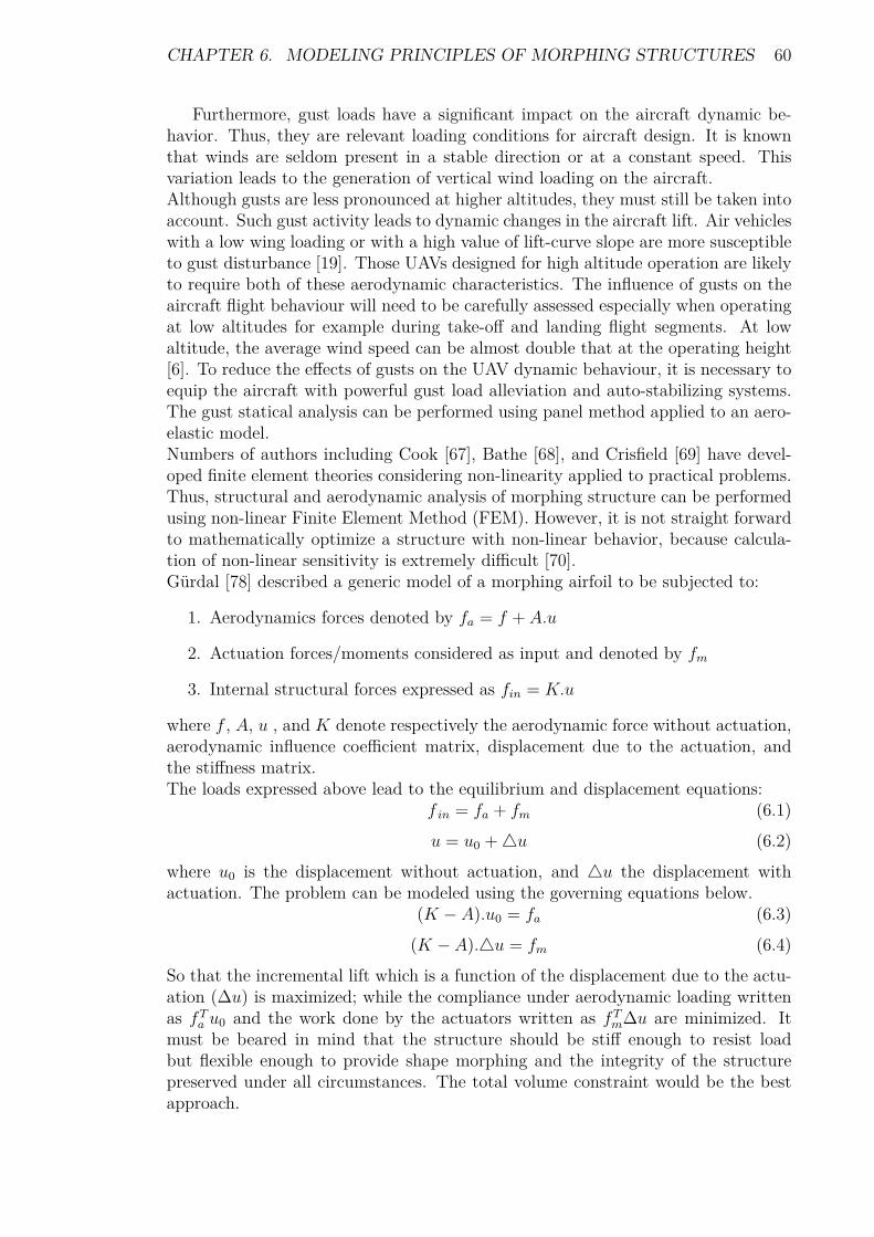
CHAPTER 6. MODELING PRINCIPLES OF MORPHING STRUCTURES 60
Furthermore, gust loads have a significant impact on the aircraft dynamic be-havior. Thus, they are relevant loading conditions for aircraft design. It is knownthat winds are seldom present in a stable direction or at a constant speed. Thisvariation leads to the generation of vertical wind loading on the aircraft.Although gusts are less pronounced at higher altitudes, they must still be taken intoaccount. Such gust activity leads to dynamic changes in the aircraft lift. Air vehicleswith a low wing loading or with a high value of lift-curve slope are more susceptibleto gust disturbance [19]. Those UAVs designed for high altitude operation are likelyto require both of these aerodynamic characteristics. The influence of gusts on theaircraft flight behaviour will need to be carefully assessed especially when operatingat low altitudes for example during take-off and landing flight segments. At lowaltitude, the average wind speed can be almost double that at the operating height[6]. To reduce the effects of gusts on the UAV dynamic behaviour, it is necessary toequip the aircraft with powerful gust load alleviation and auto-stabilizing systems.The gust statical analysis can be performed using panel method applied to an aero-elastic model.Numbers of authors including Cook [67], Bathe [68], and Crisfield [69] have devel-oped finite element theories considering non-linearity applied to practical problems.Thus, structural and aerodynamic analysis of morphing structure can be performedusing non-linear Finite Element Method (FEM). However, it is not straight forwardto mathematically optimize a structure with non-linear behavior, because calcula-tion of non-linear sensitivity is extremely difficult [70].Gürdal [78] described a generic model of a morphing airfoil to be subjected to:
1. Aerodynamics forces denoted by fa = f + A.u
2. Actuation forces/moments considered as input and denoted by fm
3. Internal structural forces expressed as fin = K.u
where f , A, u , and K denote respectively the aerodynamic force without actuation,aerodynamic influence coefficient matrix, displacement due to the actuation, andthe stiffness matrix.The loads expressed above lead to the equilibrium and displacement equations:
f in = fa + fm (6.1)u = u0 +4u (6.2)
where u0 is the displacement without actuation, and 4u the displacement withactuation. The problem can be modeled using the governing equations below.
(K − A).u0 = fa (6.3)(K − A).4u = fm (6.4)
So that the incremental lift which is a function of the displacement due to the actu-ation (∆u) is maximized; while the compliance under aerodynamic loading writtenas fTa u0 and the work done by the actuators written as fTm∆u are minimized. Itmust be beared in mind that the structure should be stiff enough to resist loadbut flexible enough to provide shape morphing and the integrity of the structurepreserved under all circumstances. The total volume constraint would be the bestapproach.

CHAPTER 6. MODELING PRINCIPLES OF MORPHING STRUCTURES 61
6.2 Force-Displacements RelationshipTo give a closed form relationship between the actuator force and structural displace-ments, Phani et al.[71] performed the analysis of single and multi-element structuralassemblies using two methods:
1. The differential approach referred to as the exact element theory based onstability functions.
2. The Rayleigh-Ritz approximate energy method based on an assumed trialfunction for the displacements.
A multi-element structure could describe the trailing edge of a wing, while a singleelement may represent the rib or spar of the wing of a micro vehicle. The differentialmethod and the approximate energy minimization technique were preferred over theconventional finite element analysis (FEA) due to their ability to pin-point the initialbuckling load, and trace the buckling path more accurately than FEA method.
6.2.1 Differential MethodStarting from a single strut subjected to an actuation force F inclined at an angleΦ as depicted in Figure 6.1; with the free body-displacement diagram in Figure 6.2,the analytical methods are extended to the trailing edge of a morphing wing asillustrated by Figure 6.3.
Figure 6.1: Member with actuator force [71].

CHAPTER 6. MODELING PRINCIPLES OF MORPHING STRUCTURES 62
Figure 6.2: Forces and displacements for a post-buckled member [71].
The moment equilibrium about a cut along the member at point B yields:M(x) = −EI d
2w
dx2 = Fcos(Φ)w +m1 − Fsin(Φ)x (6.5)
with E and I denoting respectively the material elastic modulus and the secondmoment of area of the beam. The differential equation above has the displacementcurve as a general solution:
w(x) = C1cos(βx) + C2sin(βx)− m1
P+ −Pz1x
P(6.6)
where C1 and C2 are coefficients defined by the end conditions:
1. At the fixed end, the displacement and the slope of the displacement curvevanish.
2. At full length of the strut, the displacement is assumed to be α according toFigure 6.1, while the slope of the displacement curve is zero.
and β =√
PEI
, P = Fcos(Φ), and Pz1 = −Fsin(Φ).Using stability functions which take into account the non-linear effect due to theaxial load in the member based on the moment distribution method described byLivesly and Chandler2 [72], the solution of equation 6.6 can be determined, and theflexural end-shortening can be obtained by integrating the displacement curve as:
ε = 12
L∫0
[dw
dx
]2
dx (6.7)
The net displacement along the actuator is given in terms of α and ε by a suitablecoordinate transformation from strut axes to actuator axes as:
δ(Φ) = αsin (Φ) + εcos (Φ) (6.8)2Their publication “Stability functions for structural frameworks” was found as a non printable
google electronic book.

CHAPTER 6. MODELING PRINCIPLES OF MORPHING STRUCTURES 63
6.2.2 Rayleigh-Ritz Energy MethodAlternatively, the Rayleigh-Ritz method based on the energy approximation or thetotal potential energy of the structure expressed as:
V = 12
∫ L
0EI
(d2w
dx2
)2
dx− Fsin (Φ)α− Fcos (Φ) ε (6.9)
is minimized by assuming a suitable trial function for the displacement field w(x)parametrized by α. The derivative of the potential energy equation with respect toα is set to zero, giving a close form expression for α.In the multi-element structures illustrating a morphing trailing edge (Figure 6.3),translations are produced using a hybrid system comprising of Piezo-electric stackscontolling struts AB and DE, and conventional actuators within inclined bracingelements to monitor the displacements. Additionally, the rotations are achievedby three methods: bending the individual struts BC and CD, introducing a post-buckled precompressed element FC, and differential end-shortening of the two strutsAB and DE. The energy approach, though approximate, was found to be sufficient.
Figure 6.3: Trailing edge framework for morphing wing [71].

CHAPTER 6. MODELING PRINCIPLES OF MORPHING STRUCTURES 64
6.3 Span Morphing Wing ModelA variable span morphing wing alters its wing span for various flight conditions toimprove performance by reducing the drag. The wing geometric characteristics suchas the aspect ratio and the wing area increase with the wing span expansion; whilethe span-wise lift distribution decreases for the same lift, inducing a decline in thedrag which results in performance improvement measured as an increase in range.However, the wing span-wise extension generates significant increase in the wingroot bending moment. Therefore, an analysis of a span-wise morphing wing mustcouple aerodynamic and aero-elastic investigations [75]. The aero-elastic response offlight vehicles with a concentrated structural non-linearity such as free-play, typicallyincludes flutter (a dynamic aero-elastic phenomenon), divergence (a static aero-elastic phenomenon), limit-cycle oscillation (a non-linear aero-elastic phenomenon),and chaotic motion.For the telescoping wing analysis, the wing configuration including wing retractedand wing fully extended together with basic wing geometric characteristics should beclearly presented and the computational tools stated. The doublet-hybrid method(DHM) can be used to calculate unsteady aerodynamic forces in subsonic flightregime while MSC/NASTRAN can be used for modeling the wing box structureconsisting of the main wing box and the sliding wing section. Appropriate con-straints should be applied to the wing structure with a particular attention to themoving part; since the structural characteristics of the variable span morphing wingare significantly dependent on the boundary conditions at the joint. The telescop-ing wing contains concentrated non-linearities such as free-play at the junction [75].free-play, which is a local structural non-linearity rising at the wing section interface,can be addressed using fictitious mass method3.
6.3.1 Aero-Elastic ModelAero-elastic modeling involves two aspects including a structural model, and anaerodynamic model. But in some cases, a control model is added to represent theeffects of actuators and other control elements. Thus, the exact modeling of theaero-elastic behaviour of an air vehicle implies the coupled solution of:
1. The full compressible Navier Stokes equations,
2. The full structural vibration equations.
The structural model leads to the equations of motion obtained by inserting theexpression of the system total energy ( sum of the kinetic energy and potential energywhich is composed of the internal and external energy) into Lagrange’s equationwritten as:
d
dt
(∂T
∂q
)−(∂T
∂q
)+(∂U
∂q
)= ∂V
∂q(6.10)
where T, V, U, and q denote respectively the kinetic energy, the potential energy,the internal energy, and the generalized coordinate.
3Fictitious masses are used to improve the accuracy and efficiency of modal based structuralanalyzes that involve substructure synthesis, local excitation, and local structural changes.

CHAPTER 6. MODELING PRINCIPLES OF MORPHING STRUCTURES 65
Thus, the aero-elastic equations of the wing structure are given in a matrix formas:
[M ] {x}+ [K] {x} = {f} (6.11)where [M ] and [K] denote the mass and stiffness matrices respectively, while {f}and {x} are the aerodynamic load and structural displacement vectors respectively.The aerodynamic load vector can be written as:
{f} = {{f}}+ {f0} (6.12)where {{f}} is due to the wing deflection and {f0} resulting from the airfoil shapeor angle of attack.For the determination of a static deformation of the structure (x = 0), the vectorialequations
[K] {x} = {f} (6.13)have to be solved using for instance the modal approach.
6.3.2 Aerodynamic ModelAerodynamic models depend on flow regime and simplicity. Four flow regimes maybe considered for aero-elasticity investigations [76]:
1. Incompressible,
2. Subsonic,
3. Transonic,
4. Supersonic.
The aerodynamic loads can be computed using Vortex Lattice Method (VLM). VLMprovides a platform considering linearized and non-linearized compressible flow ap-proaches. Additionally, compressibility effects can be accounted for by correctingthe airflow density using Prandlt-Glauert correction [81]. A simplified modelingconsists of ignoring the effect of the wake vortices4. Thus, a quasi-steady model isperformed with the assumption that there are only the lift placed on the quarterchord, and the pitching moment around the flexural axis, contributing to the aero-dynamic forces. Both lift and pitching moment coefficients can be computed usingintegral equations from thin airfoil theory.In addition to the aerodynamic forces mentioned above, the air exerts another forceon the airfoil: the wing forces a mass of air during its acceleration or decelerationmotion. The air reaction force is known as the added mass effect5 [76]. This forcecauses both lift and moment contributions.
4The instantaneous aerodynamic forces depend not only on the instantaneous position of theairfoil but also on the position and strength of the wake vortices [76].
5Added mass or virtual mass is the inertia added to a system because an accelerating or decel-erating body must move some volume of surrounding fluid as it moves through it [77].

CHAPTER 6. MODELING PRINCIPLES OF MORPHING STRUCTURES 66
6.4 Camber Morphing ModelVos et al.[83] describe a semi analytical method and the Theodorsen theory tocompute the pressure distribution over a camber morphing airfoil to predict the liftover the morphing part of a laminate wing actuated by post-buckled precompressed(PBP) actuators.
6.4.1 Structural ModelPBP actuators belong to a subset of low net passive stiffness or zero net passive stiff-ness class actuators. These actuators work on the fundamental principle expressedas:
Fpiezo = (K −Ksp)4x (6.14)where Ksp , K, and 4x denote respectively a negative spring rate mechanism, thepassive stiffness of the structure, and the generated deflection. The morphing wingpanel employing PBP actuators on the camber is depicted in Figure 6.4.
Figure 6.4: Camber line with PBP [83].

CHAPTER 6. MODELING PRINCIPLES OF MORPHING STRUCTURES 67
Figure 6.5 illustrates the schematic model for the analysis.
Figure 6.5: Wing morphing part model [83].
From Figure 6.5, the morphing part of the airfoil is loaded by the skin modeled asspring with tension force F0 and spring stiffness K and the aerodynamic end force,Pm
2 , resulting from the pressure distribution over the airfoil. The trailing edge ismodeled as a mass positioned at the end of the actuator. It is assumed that the skincan be modeled as a membrane which will not exhibit any out-of-plane displacementdue to the aerodynamic force since the precompressed force in the skin is larger thatthe aerodynamic load. Therefore, a uniform stress distribution is expected throughthe skin. Hence, half of the aerodynamic load is carried by the morphing part andthe other half by the rigid part.Subsequently, resultant forces and moments from the actuator in the laminate wingskin are obtained by integrating the stress over the skin thickness according to [84],by applying the laminate notations illustrated in Figure 6.6.
N =∫ t
2
−t2
σdz (6.15)
M =∫ t
2
−t2
σzdz (6.16)
The stress resultant is in the form of forces per unit length and moments per unitlength.

CHAPTER 6. MODELING PRINCIPLES OF MORPHING STRUCTURES 68
Figure 6.6: Stress and moment resultants for a laminate element [84].
The forces and moments in the laminate that are induced by the actuator elementsare a function of the Piezo-electric zero (virgin) strain denoted by Λ. Assuming noexternal loading, and neglecting thermal effects, the in-plane laminate strains andcurvatures are described by:[
A BB D
]a
(Λ0
)a
=[A BB D
]l
(εκ
)l
(6.17)
where the subscript a and l stand for actuator and laminate respectively. Theequations above allow to define the relationship between the actuation zero strainΛ and the laminate curvature κ once the values of D and B are known from theclassical laminate plate theory. The free strain of the actuator in the laminate isone of the driving parameters of the eventual deflection of the morphing wing [83].The out-of-plane displacement due to external loading on the PBP can be accessedthrough Euler-Bernoulli beam6 equation and by applying Rayleigh-Ritz method7 [86]using assumed shape functions ψi. The principle of assumed shapes is somewhatakin to using a Fourier series to represent a time signal by the summation of a seriesof sinusoids of different amplitude and phase.
6The Euler-Bernoulli equation describes the relationship between the beam’s deflection and theapplied load [85]: ∂2
∂x2
(EI ∂2u
∂x2
)= w
7The Rayleigh–Ritz approach is used to represent the deformation of the system by a finiteseries of known assumed deformation shapes multiplied by unknown coefficients. The idea is thatthis combination of shapes represents the true deformation of the system as closely as possible.Themore shapes used, the more accurate will be the approximation.

CHAPTER 6. MODELING PRINCIPLES OF MORPHING STRUCTURES 69
For a system where the deformation varies in only one dimension, the bendingdeformation is given by:
w(x, t) =N∑i=1
qi(t)ψi(x) (6.18)
where ψi(x) is the ith assumed deformation shape (a function of x), qi(t) is the ithunknown coefficient (the generalized coordinate), which is a function of time, andN is the number of terms in the series. Applying the partial differential equation6.10 leads to the beam state equation:
Mq +Kq = Pm2 ψ(L) (6.19)
which yields, when solved for N number of shape functions, an approximate solutionfor the aerodynamic load represented at the right side of the equation above. Theexact solution is given by equation 6.10. Furthermore, a Vortex Lattice code can beused to evaluate the present semi analytical method.
6.4.2 Theodorsen’s ModelTheodorsen’s function C(k), a complex quantity8, is used to model the changesin amplitude and phase of the sinusoidal unsteady aerodynamic forces relative tothe quasi-steady forces for different reduced frequencies [86]. This function is animportant component in predicting the starting of flutter in the frequency domainand in the analysis of the response to continuous turbulence.The solution of the flow around the airfoil undergoing harmonic oscillations can bedivided into two parts [86]:
(a) Circulatory terms: the lift and moment terms occurring due to the vor-ticity in the flow are related to Theodorsen’s function.
(b) Non-circulatory terms: the apparent inertia forces whose creation is notrelated to vorticity. These internal forces are also referred to as added massesas seen in the previous section. For example as the airfoil moves, a cylindricalmass of air accelerates with the airfoil and introduces a reactive force andmoment upon the airfoil. These terms are of minor importance for bendingor torsion type flutter of cantilever wings at low reduced frequencies, but theyare significant for flutter of control surfaces at higher reduced frequencies.
8C(k) = F (k) + iG(k), where k is the reduced frequency defined as k = ωbU
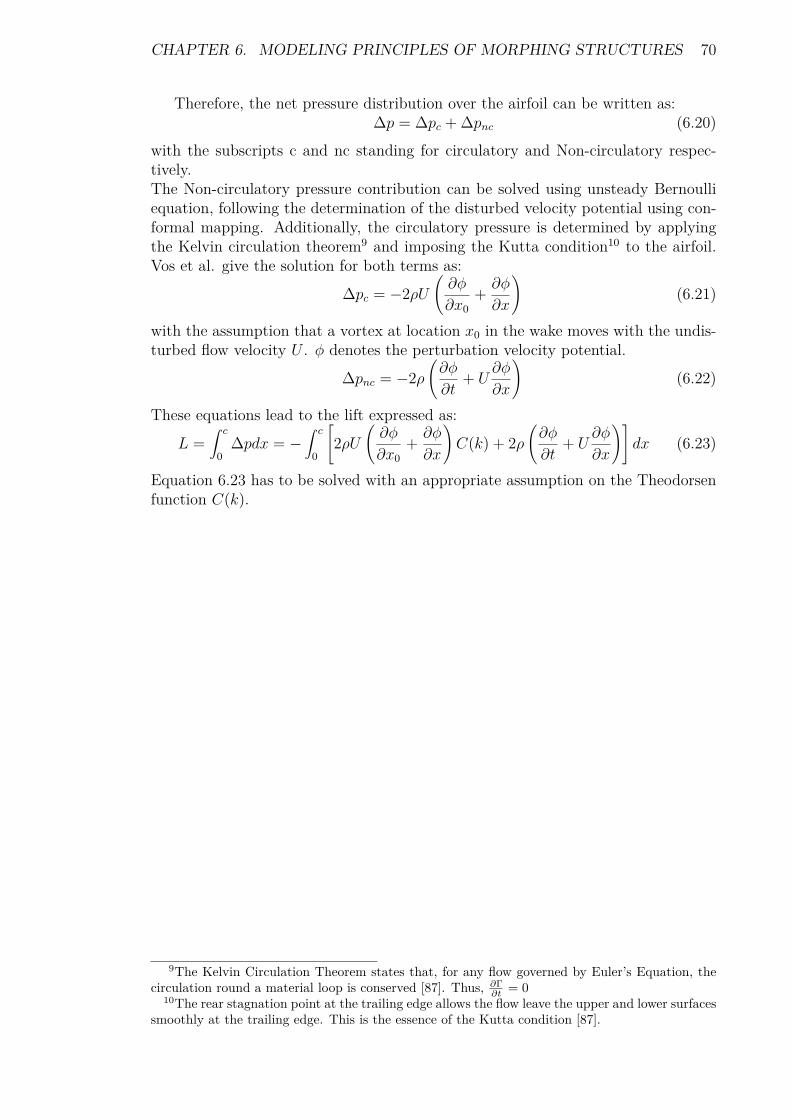
CHAPTER 6. MODELING PRINCIPLES OF MORPHING STRUCTURES 70
Therefore, the net pressure distribution over the airfoil can be written as:∆p = ∆pc + ∆pnc (6.20)
with the subscripts c and nc standing for circulatory and Non-circulatory respec-tively.The Non-circulatory pressure contribution can be solved using unsteady Bernoulliequation, following the determination of the disturbed velocity potential using con-formal mapping. Additionally, the circulatory pressure is determined by applyingthe Kelvin circulation theorem9 and imposing the Kutta condition10 to the airfoil.Vos et al. give the solution for both terms as:
∆pc = −2ρU(∂φ
∂x0+ ∂φ
∂x
)(6.21)
with the assumption that a vortex at location x0 in the wake moves with the undis-turbed flow velocity U . φ denotes the perturbation velocity potential.
∆pnc = −2ρ(∂φ
∂t+ U
∂φ
∂x
)(6.22)
These equations lead to the lift expressed as:
L =∫ c
0∆pdx = −
∫ c
0
[2ρU
(∂φ
∂x0+ ∂φ
∂x
)C(k) + 2ρ
(∂φ
∂t+ U
∂φ
∂x
)]dx (6.23)
Equation 6.23 has to be solved with an appropriate assumption on the Theodorsenfunction C(k).
9The Kelvin Circulation Theorem states that, for any flow governed by Euler’s Equation, thecirculation round a material loop is conserved [87]. Thus, ∂Γ
∂t = 010The rear stagnation point at the trailing edge allows the flow leave the upper and lower surfaces
smoothly at the trailing edge. This is the essence of the Kutta condition [87].

CHAPTER 6. MODELING PRINCIPLES OF MORPHING STRUCTURES 71
6.5 Continuously Morphing Wing ModelAmeri el at.[131] whose work is reviewed in this section, present a conceptual ap-proach for the modeling of a small-scale flying wing with active winglets actuatedvia a distribution of actuators. The conceptual approach allows the tailoring ofthe main parameters influencing the flexibility of the structures. The goal of theirwork was to modify the flying wing from its discrete surfaces concept, actuated viasingle torque actuator, to a seamless continuous concept actuated via a distributionof actuators. They used equivalent plate continuum models to simulate morphingstructures with the assumption that only global quantities of the response are ofconcern. An equivalent plate model approach was chosen instead of the widely usedequivalent beam model because the beam model is not suitable for low aspect ratiowings made of composite materials.The challenges with equivalent plate models is the difficulty of capturing local effects.When simple polynomial Ritz based functions are used, the resulting numericalanalysis is significantly simplified leading to explicit expressions of stiffness andmass matrix in terms of system design variables.The plate representation of a structure is considered as a bridge between the simplebeam model and the complex, but accurate Finite Element (FE) model. Existingsolutions for plates are classified according to the deformation theory used:
a) The Classical Plate Theory (CPT). The CPT is based on the Kirchhoff-Lovehypothesis. This hypothesis states that a straight line normal to the platemiddle surface remains straight and normal during the deformation process.The CPT approach works well when through-thickness shear deformations arenegligible. This is applicable to thin isotropic plates.
b) The First-order Shear Deformation Theory (FSDT). The FSDT is based on theReissner-Mindlin model. It relaxes the constraint that a normal to the mid-surface stays normal to the mid-surface after deformation. It allows a uniformtransverse shear strain. Due to its simplicity, the FSDT has a low computationrequirement.
c) The Higher-order Shear Deformation Theory (HSDT). The HSDT is based on amore accurate representation of the local distribution of the transverse shear.
6.5.1 Structural ModelThe wing is modeled by applying the First-order Shear Deformation Theory (FSDT).The wing geometry is defined by a small number of sizing and shape design variables.Particularly, the skin depth and thickness, spar caps, ribs and spar thicknesses areall defined through polynomials with respect to the coordinates of a reference planewhere the wing trapezoid is defined. Similarly, displacements are defined by polyno-mials whose coefficients represent the time-dependent generalized coordinates. Theminimization of the total energy leads to the Lagrange equations and the mass andstiffness matrices are evaluated by analytical integration.

CHAPTER 6. MODELING PRINCIPLES OF MORPHING STRUCTURES 72
Geometry DefinitionThe geometry of the wing is depicted in Figure 6.7. It represents a generic trape-zoidal wing shape defined over a global left-handed coordinate system x, y and z.It is composed of spars, ribs and caps.
Figure 6.7: Generic trapezoidal wing (left) and wing- box (right)[127].
The wing is defined over the following bounded set:x :
{x1 + ytan (ΛLE) < x < x1 + ytan (ΛLE) + c (y)} (6.24)y :
{y1 < y < y2} (6.25)where ΛLE is the leading edge sweep angle and c(y) is the local chord.A depth distribution is defined over the bounded region of the wing. This depthdistribution is the height of each composite skin layer forming the wing shape withrespect to a reference plane z = 0. The i − th layer height zski is described by apolynomial series in the x and y global coordinates as follows:
zski (x, y) =Nk∑k=1
Hskik xmkynk (6.26)
where the Hski coefficients are used as design variables. Under the hypothesis of asmall thickness-to-depth ratio, two sets of depth are taken into account. These arethe upper zup, and the lower surfaces zlo.Similarly, a distribution of the i − th composite layer thickness is defined over thewing planform:
tski (x, y) =Nj∑j=1
T skij xmjynj (6.27)

CHAPTER 6. MODELING PRINCIPLES OF MORPHING STRUCTURES 73
Each spar is identified by a spar line having the general expression:xspj (y) = a1y + a2 (6.28)
This linear equation locates the η axis of a local coordinates system (ξ, η, z) whichis rotated with respect to the global system by an angle Λspj. The thickness distri-bution and cap area of the spars are expressed as simple polynomials in y, as tspj (y)and Aspj (y) respectively. Each rib is modeled as parallel to the longitudinal axis,and thus is identified simply by the line y = yrbk , with thickness distribution trbk (x)and spar cap area Arbk (x).
Material PropertiesEach skin layer has its own fibre direction in the x-y plane and the constitutiveequations reflect a plane strain behavior:
σski = Qskiεski (6.29)
where σski =[σxx σyy σxy
]Tand εski =
[εxx εyy γxy
]Tare the stress and
strain vectors respectively. Qski is the constitutive matrix of the i− th layer.The constitutive behaviour of each spar is defined in the local (ξ, η, z) coordinatesystem so that
σspj = Qspj εspj (6.30)
where σspj =[σηη σxz
]Tand εspj =
[εηη γηz
]TThis means that the spars sustain only axial stress and the transverse shear. Thespar strain vector in global coordinates εspj =
[εxx εyy γxy γxz γyz
]Tis related
to the strain in local coordinates by means of the following relation:εspj = Tεspj (6.31)
where T is the global-to-local rotation matrix for the spar strain vector defined as
T =[s2 (Λspj ) c2 (Λspj ) s (Λspj ) c (Λspj ) 0 0
0 0 0 s (Λspj ) c (Λspj )
](6.32)
where s = sinus and c = cosinusThe spar caps sustain only axial stress, and thus the constitutive equation is simply
σηη = Eεηη (6.33)A rotation vector gives the global-to-local transformation:
εηη = tTεspcr (6.34)
where εspcr =[εxx εyy γxy
]Tis the spar cap strain vector in global coordinates
and the rotation matrix is given byt =
[s2 (Λspj ) c2 (Λspj ) s (Λspj ) c (Λspj )
]T(6.35)
Similar relations are obtained for the ribs and the rib caps. They behave in a similarway to the spars and spar caps previously described, but the local η axis is rotatedby an angle Λrbk = 90◦ and coincides with the x axis.

CHAPTER 6. MODELING PRINCIPLES OF MORPHING STRUCTURES 74
First-Order Shear DeformationThe first-order shear deformation plate theory (FSDT) is based on the Reissner-Mindlin assumption where the u, v and w displacements of the wing are approxi-mated as
u (x, y, z, t) = u0 (x, y, t) + zψx (x, y, t) (6.36)v (x, y, z, t) = v0 (x, y, t) + zψy (x, y, t) (6.37)
w (x, y, z, t) = w0 (x, y, t) (6.38)where u0, v0 and w0 denote the corresponding mid-plane displacements in the x, y, zdirections; ψx and ψy are unknown functions giving contributions to the transverseshear deformations in the x− z and y − z planes respectively.Under the hypothesis of small surface curvatures, the wing skins are modeled as athin plane stress panel, and the strain field is given by:
εxx = u,x (6.39)εyy = v,y (6.40)
γxy = u,y + v,x (6.41)while the transverse shear fields captured by the spars and ribs are:
γxz = u,z + w,x (6.42)γyz = u,z + w,y (6.43)
Substituting equations (6.36) through (6.38) into equations (6.42) and (6.43) showsthat ψx and ψy are the actual rotations of the sections about the y and x axesrespectively:
ψx = γxz − w0,x (6.44)ψy = γyz − w0,y (6.45)
Mass And Stiffness MatricesThe equivalent plate theory is based on the assumption that the deformation fieldis approximated by a series of Ritz polynomials. Thus, the unknowns in equations(6.36) through (6.38) are expressed as:
u0 (x, y, t) = a1 (x, y)T q1(t) (6.46)v0 (x, y, t) = a2 (x, y)T q2(t) (6.47)ψx (x, y, t) = a3 (x, y)T q3(t) (6.48)ψy (x, y, t) = a4 (x, y)T q4(t) (6.49)
w0 (x, y, t) = a5 (x, y)T q5(t) (6.50)
where ai =[..., xnpymp , ...
]Tare vectors containing the polynomial terms or
shape functions, which may be of different lengths. The qi are vectors of the time-dependent generalized coordinates.

CHAPTER 6. MODELING PRINCIPLES OF MORPHING STRUCTURES 75
Substituting equations (6.46) trough (6.50) into equations (6.36) through (6.38)and defining the displacement vector u =
[u v w
]Tand the vector of generalized
coordinates q =[
qT1 qT2 qT3 qT4 qT5]T, leads to:
u = Sq (6.51)where S = S (x, y, z) is the matrix relating the generalized coordinates to the physi-cal displacements. Substituting equations (6.46) trough (6.50) into equations (6.39)trough (6.41) and equations (6.42) and (6.43) leads to:
εski = Eq (6.52)εspj = Wq (6.53)
where E = E (x, y, z) andW = W (x, y, z) are matrices providing the deformationfield for the skin layers and for the spars respectively.Finally, the mass and stiffness matrices for each element of the wing are obtainedusing an energy approach. Specifically, the kinetic (T ) and elastic potential (ε)contributions to the total energy of the wing are defined for the skin, spar and sparcaps (the procedure is identical for ribs and rib caps) and the application of theLagrange equations
d
dt
(∂T
∂qn
)−(∂T
∂qn
)+(∂ε
∂qn
)= 0 (6.54)
with n = 1, 2, ...,Nq minimizes the total energy with respect to the generalizedcoordinates, and gives the mass and stiffness matrices. In practice, this procedurerequires the computation of integrals over the geometric domain. Since the natureof the shape functions and the definition of depths, thicknesses and areas are allpolynomials in x and y, the integrals may be calculated in closed form, and nonumerical evaluation is required.
Wing SkinsThe contribution to the kinetic energy of an infinitesimal skin element of volumetski (x, y) dxdy and of density ρ, is given by
dT ski = 12ρt
ski (x, y) uT udxdy (6.55)
Substituting equation (6.51) and integrating over the wing domain defined by equa-tions (6.24) and (6.25), gives the total kinetic energy as:
T ski = 12 q
T(∫ ∫
ρtski (x, y)S(x, y, zski
)TS(x, y, zski
)dxdy
)q (6.56)
T ski = 12 q
TM ski qSimilarly, the potential energy of the infinitesimal skin element is
dεski = 12t
ski (x, y) εskiTσskidxdy (6.57)
Substituting equations (6.29) and (6.52) and integrating over the wing domain, givesthe total potential energy as
εski = 12q
T(∫ ∫
tski (x, y)E(x, y, zski
)TQskiE
(x, y, zski
)dxdy
)q (6.58)
εski = 12q
TKskiq

CHAPTER 6. MODELING PRINCIPLES OF MORPHING STRUCTURES 76
Wing SparsThe contribution to the kinetic energy of an infinitesimal spar element of volumetspj (η)dηdz and of density ρ is given by:
dT spj = 12ρt
spj (η) uT udηdz (6.59)
Substituting equation (6.50) and considering the global-to-local coordinate systemrelation,
dη = dy
cos (Λspj ) (6.60)
the double integration over the wing length and between the lower an upper limitof the spar leads to the following expression for the mass matrix:
M spj = ρ
cos (Λspj )
∫ zup(xspj ,y)zlo(xspj ,y)
∫ y2
y1tspj (y)S (xspj , y, z)T S (xspj , y, z) dydz (6.61)
where xspj = xspj (y) is the spar line as defined in equation (6.28). The potentialenergy of the infinitesimal spar element is defined as:
dU spj = 12t
spj (η) εspjT σspjdηdz (6.62)
Equations (6.30), (6.31), (6.53) and (6.60) give the expression for the spar stiffnessmatrixKspj = 1
cos (Λspj )
∫ zup(xspj ,y)zlo(xspj ,y)
∫ y2
y1tspj (y)ETT (Λspj )T Qspj
T (Λspj )Edydz (6.63)
with E = E (xspj , y, z)
Spar CapsThe volume of an infinitesimal spar cap element, belonging to the j − th spar,is Aspcr (y) dηdx. Thus, following the procedure adopted in the previous section,expressions for the mass and stiffness matrices for the spar caps are:
M spcr = ρ
cos (Λspj )
∫ y2
y1Aspcr (y)S (xspj , y, z∗)T S (xspj , y, z∗) dy (6.64)
Kspcr = E
cos (Λspj )
∫ y2
y1Aspcr (y)W (xspj , y, z∗)T ttTW (xspj , y, z∗) dy (6.65)
where z∗ = zup/lo (xspj , y) is the height at which the spar cap is defined.Finally, mass and stiffness matrices of the whole structure are given by summingthe contributions of all the elements of the wing.
M =∑M ski +
∑M spj +
∑M spcr +
∑M rbk +
∑M rbcs (6.66)
K =∑Kski +
∑Kspj +
∑Kspcr +
∑Krbk +
∑Krbcs (6.67)

CHAPTER 6. MODELING PRINCIPLES OF MORPHING STRUCTURES 77
Multiple Plate CapabilityIf the system comprises more than one plate, each of them with arbitrary orientationin space, a global coordinate system has to be set up. A local coordinate system,fixed with respect to the undeformed reference state, is defined for each plate. Thus,if the same set of polynomial is used for each plate, the global number of degrees offreedom will be NP × Nq where NP is the number of plates and Nq is the numberof degrees of freedom of each plate. Finally, each plate will add to the system acontribution to the kinetic and potential energies that is evaluated with respect tothe local coordinate system and thus, the formulation obtained in previous sectionsis used for this purpose.Ameri el at. formulated the displacement compatibility between contiguous platesby means of stiff springs. Both rotational and longitudinal springs are used intheir work. The displacement compatibility is imposed in global coordinates; butexpressed in local coordinates as follows: Consider the contiguous plates i and jand let Ri and Rj be respectively the global-to-local transformation matrix of eachplate. In order to impose the displacement compatibility of the point Ai belongingto body i and the point Aj belonging to body j , the following expression leads tothe potential energy of the springs linking Ai and Aj:
ε = 12(uiAi − u
jAj
)Tkx 0 0 0 00 ky 0 0 00 0 kz 0 00 0 0 krx 00 0 0 0 kry
(uiAi − u
jAj
)(6.68)
where u collects the elastic displacements and the rotations of a point of the struc-ture in global coordinates. Thus, the global displacement vector can be expressedin terms of the local displacement u, via a geometrical rotation matrix, and, con-sequently, in terms of the Lagrangian coordinates via the matrix of shape functionsS.
u = Ru = RSq (6.69)Substituting equation (6.69) in to equation (6.68) leads to the following expressionfor the potential energy
ε = 12(qTi Ks
iiqi + qTjKsjjqj + qTi Ks
ijqj + qTjKsjiqi
)(6.70)
where the generic contribution to the stiffness matrix is defined as
Kslp = STAlR
lT
kx 0 0 0 00 ky 0 0 00 0 kz 0 00 0 0 krx 00 0 0 0 kry
RpSAp (6.71)
with l = i,j and p = i,j

CHAPTER 6. MODELING PRINCIPLES OF MORPHING STRUCTURES 78
6.5.2 Piezo And Thermo Actuator ModelA patch of Piezo or thermo actuator undergoes a strain variation when an electricalfield or a thermal variation respectively, is imposed through the thickness. Assumingthat the patches are thin enough to be modelled as plates and assuming a plane-strain behavior, the previous relations can be expressed analytically as:
ε∆T =
ε11ε22γ12
=
α1α20
∆T (6.72)
εV =
ε11ε22γ12
=
d13d230
Vt
(6.73)
where ε∆T and εV are the strains defined in the principal material coordinatesof each patch, α1 and α2 are the thermal expansion coefficients in the 1 and 2directions respectively, d13 and d23 [m/V ] are the Piezo-electric constants; ∆T isthe temperature variation input with respect to a reference temperature while theratio V/t, between the input voltage V and the distance between the electrodes t,represents the through-the-thickness electric field.The strain vectors in global coordinates ε∆T and εV , is obtained by applying therotation matrix T which is a function of the angle θ. The angle θ defines theorientation of the principal material coordinate system with respect to the global,and is defined as follows:
T (θ) =
m2 n2 mnn2 m2 −mn−2mn 2mn (m2 − n2)
(6.74)
where m = cos (θ) n = sin (θ) such thatε = T (θ) ε (6.75)
Using this definition, the strain vectors in global coordinates is obtained as:ε∆T = T (θ)−1 b∆T∆T (6.76)
εV = T (θ)−1 bVV
t(6.77)
where b∆T =[α1 α2 0
]Tand bV =
[d13 d23 0
]TThe strain due to the stress field εS is obtained by subtracting from the total strainfield ε the contribution due to the thermal and the Piezo-electric strains.
εS = ε− (ε∆T + εV ) (6.78)Recalling equation (6.52), linking the total strain vector to the generalized coordi-nates vector for an infinitesimal skin element, and equations (6.76) and (6.77), theprevious equation becomes
εS = Eq − T (θ)−1 b∆T∆T − T (θ)−1 bVV
t(6.79)
The constitutive relations providing the stress vector σ =[σxx σyy σxy
]Tis
given by:σ = QεS (6.80)
where Q is the constitutive matrix rotated in global coordinates.

CHAPTER 6. MODELING PRINCIPLES OF MORPHING STRUCTURES 79
The equations describing the interaction between the smart patches and the struc-ture is obtained via a virtual work approach. The virtual work δWε done by theelastic forces on an infinitesimal element of Piezo-thermo actuator of volume tdxdyis defined as:δWε = δεTσtdxdy = δqT
{ETQ
(Eq − T (θ)−1 b∆T∆T − T (θ)−1 bV
V
t
)}tdxdy
(6.81)The inertial forces fi acting on an infinitesimal element of mass ρtdxdy is definedusing d’Alembert principle:
fi = −ρtudxdy = −Sqρtdxdy (6.82)Thus, the virtual work dWi done by the inertial forces becomes:
dWi = duTf i = −δqTSTSqρtdxdy (6.83)Similarly, the virtual work δWext done by the external forces fext per unit area isdefined by:
dWext = duTf extdxdy = δqTSTf extdxdy (6.84)The equilibrium condition states that the external and inertial virtual works mustbalance the internal work done by the stresses:
dWext = dWi + δWε (6.85)Substituting in the previous equation, equations (6.81), (6.83), and (6.84), leads to:
δqT{ETQEq −ETQT (θ)−1 b∆T∆T −ETQT (θ)−1 bV
V
t
}tdxdy (6.86)
= δqT{−ρtSTSq + STf ext
}dxdy
which is integrated over the area SA of the actuator patch, leading toMAq +KAq = eext + eV V + e∆T∆T (6.87)
whereMA =
∫ ∫SASTSρtdxdy (6.88)
KA =∫ ∫
SAETQEtdxdy (6.89)
eext =∫ ∫
SASTf extdxdy (6.90)
eV =(∫ ∫
SAETQT (θ)−1 dxdy
)bV (6.91)
e∆T =(∫ ∫
SAETQT (θ)−1 tdxdy
)b∆T (6.92)
where MA and KA are the mass and stiffness contributions of the strain actuatorto be added to the total mass and stiffness matrices of the structure, while eV ande∆T are the generalized vectors providing to the structure the effect of an appliedvoltage and a temperature variation, respectively. If NA actuators are placed overthe wing surface, the contribution of each actuator has to be included. If the patchdimensions are small compared to the whole skin area, then the previous equationscan be discretized and evaluated with respect to the center point coordinates of thepatch, namely xA, yA and zA. For instance equation (6.88) becomes
MA = S(xA, yAzA
)TS(xA, yAzA)ρtab (6.93)
where a and b are the width and length of the patch, supposed to be rectangular.

CHAPTER 6. MODELING PRINCIPLES OF MORPHING STRUCTURES 80
6.6 Snap-Through ModelSchultz et al.[120] discussed the concept of using a piezoceramic actuator (Macro-Fiber Composite (MFC) actuator) bonded to a side of a two-layer unsymmetriccross-ply [0/90]T laminate to provide the moments necessary to snap the laminatefrom one stable equilibrium shape to another. They developed a model based onthe Rayleigh-Ritz technique and the use of energy and variational methods. Ananalytical model was developed in three steps including cooling the cured laminate,bonding the actuator to the laminate, and applying voltage to the laminate-actuatorcombination. These steps are reviewed in this section. Figure 6.8 illustrates thelaminate-actuator geometry. The laminate is considered to be fixed at the geometriccenter, and with no external applied loads.Accordingly, in each of the three steps, the three components of the displacementof the geometric mid-surface of the laminate (the reference surface in this analysis)are approximated by:
u0 = c5x+ 13c6x
3 + c7xy2 − 1
6c21x
3 − 18c1c3x
4 − 140c
23x
5 (6.94)
v0 = c8y + c9x2y + 1
3c10y3 − 1
6c22y
3 − 18c2c4y
4 − 140c
24y
5 (6.95)
w0 = 12(c1x
2 + c2y4)
+ 16(c3x
3 + c4y3)
(6.96)
where u, v, and w are the displacements in the x, y, and z directions, respectively.The 10 parameters c1 through c10 are unknown coefficients to be determined. Be-cause of symmetry requirements on the displacement, the third order w-displacementpolynomial can not be used to represent the w-displacement field over the entire lam-inate. However, a quarter-symmetry argument is applied to allow the use of thispolynomial to represent the w-displacement field. Then, the total potential energyis calculated over only one-quarter of the laminate.

CHAPTER 6. MODELING PRINCIPLES OF MORPHING STRUCTURES 81
Figure 6.8: Geometry of laminate-actuator combination [120].
Step I: Laminate Cooling ModelThe first step of the model is to determine the initial cooled shape of the two-layer[0/90]T laminate. Because this step does not include the actuator, and no forcesare applied to the laminate, only thermal effects within the laminate are considered.Accordingly, the total potential energy, Π, in this step is the strain energy of thecooled laminate, Π1, given by:
Π = Π1 = 41
2
∫ Lx2
0
∫ Ly2
0
∫ z2
z0
[(σx − σTx
)εx +
(σy − σTy
)εy +
(σxy − σTxy
)γxy
]dxdydz
(6.97)
where σ denotes the stress in the laminate, σT is the thermally induced stress, ε andγxy represent the strains. Additionally, Lx and Ly are the side lengths of the laminateas depicted in Figure 6.8, the thickness coordinates z0 and z2 are the coordinatesfor the bottom of the 0◦ graphite-epoxy layer and the top of the 90◦ graphite-epoxylayer, respectively.

CHAPTER 6. MODELING PRINCIPLES OF MORPHING STRUCTURES 82
The stresses are given byσx = Q11εx + Q12εy + Q16γxy − σTx (6.98)σy = Q12εx + Q22εy + Q26γxy − σTy (6.99)
σxy = Q16εx + Q26εy + Q66γxy − σTxy (6.100)
where Q denotes the transformed reduced stiffnesses of the graphite-epoxy layers.The thermally induced stresses are given by:
σTx = Q11εTx + Q12ε
Ty + Q16γ
Txy (6.101)
σTy = Q12εTx + Q22ε
Ty + Q26γ
Txy (6.102)
σTxy = Q16εTx + Q26ε
Ty + Q66γ
Txy (6.103)
withεTx = αx∆T (6.104)εTy = αy∆T (6.105)
γTxy = αxy∆T = 0 (6.106)where α denotes the coefficient of thermal deformation of the layer and ∆T thetemperature change from the cure temperature to room temperature which is theoperating temperature in the case in hands.For small strains and moderate rotations, the mid-surface strains and curvaturesin the laminate are given by the Von Kárrmán approximation through the moregeneral strain-displacement relations:
ε0x = ∂u0
∂x+ 1
2
(∂w0
∂x
)2
and/κ0x = −∂
2w0
∂x2 (6.107)
ε0y = ∂v0
∂y+ 1
2
(∂w0
∂y
)2
and/κ0y = −∂
2w0
∂y2 (6.108)
γ0xy = ∂u0
∂y+ ∂v0
∂x+ ∂w0
∂x
∂w0
∂yand/κ0
xy = −2 ∂2w0
∂x∂y(6.109)
According to the Kirchhoff hypothesis, the strains as a function of the thicknesslocation, z, are given by
εx = ε0x + zκ0
x (6.110)εy = ε0
y + zκ0y (6.111)
γxy = γ0xy + zκ0
xy (6.112)By substituting equations (6.94) through (6.96) into equations (6.107) through(6.109) and equations (6.110) through (6.112) and, in turn, substituting these re-sults into equations (6.98) through (6.100) and equation (6.97), taking into accountequations (6.101) through and (6.106), and carrying out the integrations of equa-tion (6.97), the total potential energy is reduced to an algebraic equation in termsof material properties, geometry, and the coefficients c1 through c10.
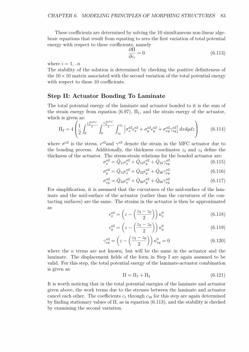
CHAPTER 6. MODELING PRINCIPLES OF MORPHING STRUCTURES 83
These coefficients are determined by solving the 10 simultaneous non-linear alge-braic equations that result from equating to zero the first variation of total potentialenergy with respect to these coefficients, namely
∂Π∂ci
= 0 (6.113)
where i = 1, ..nThe stability of the solution is determined by checking the positive definiteness ofthe 10×10 matrix associated with the second variation of the total potential energywith respect to these 10 coefficients.
Step II: Actuator Bonding To LaminateThe total potential energy of the laminate and actuator bonded to it is the sum ofthe strain energy from equation (6.97), Π1, and the strain energy of the actuator,which is given as:
Π2 = 4
12
∫ LMF Cx
2
0
∫ LMF Cy
2
0
∫ z3
z2
[σa2x ε
a2x + σa2
y εa2y + σa2
xyγa2xy
]dxdydz
(6.114)
where σa2 is the stress, εa2and γa2 denote the strain in the MFC actuator due tothe bonding process. Additionally, the thickness coordinates z2 and z3 define thethickness of the actuator. The stress-strain relations for the bonded actuator are:
σa2x = Q11ε
a2x + Q12ε
a2y + Q16γ
a2xy (6.115)
σa2y = Q12ε
a2x + Q22ε
a2y + Q26γ
a2xy (6.116)
σa2xy = Q16ε
a2x + Q26ε
a2y + Q66γ
a2xy (6.117)
For simplification, it is assumed that the curvatures of the mid-surface of the lam-inate and the mid-surface of the actuator (rather than the curvatures of the con-tacting surfaces) are the same. The strains in the actuator is then be approximatedas
εa2x =
(z −
(z3 − z0
2
))κ0x (6.118)
εa2y =
(z −
(z3 − z0
2
))κ0y (6.119)
γa2xy =
(z −
(z3 − z0
2
))κ0xy = 0 (6.120)
where the κ terms are not known, but will be the same in the actuator and thelaminate. The displacement fields of the form in Step I are again assumed to bevalid. For this step, the total potential energy of the laminate-actuator combinationis given as:
Π = Π1 + Π2 (6.121)It is worth noticing that in the total potential energies of the laminate and actuatorgiven above, the work terms due to the stresses between the laminate and actuatorcancel each other. The coefficients c1 through c10 for this step are again determinedby finding stationary values of Π, as in equation (6.113), and the stability is checkedby examining the second variation.

CHAPTER 6. MODELING PRINCIPLES OF MORPHING STRUCTURES 84
Step III: Actuation of The MFCThis step considers the laminate-actuator combination with no slipping between thelaminate and the actuator, and includes the deformation due to voltage applied tothe actuator. The initial shape is specified by the coefficients c1 through c10 associ-ated with the shape determined from Step II. For Step III, these known coefficientsare renamed ci1 through ci10, respectively. The superscript ‘i’ denotes ‘initial.’The total potential energy of the model is broken into the laminate contribution, Π1,and the actuator contribution, Π3. The contribution to the total potential energyfrom the MFC actuator is then written as:
Π3 = 4
12
∫ LMF Cx
2
0
∫ LMF Cy
2
0
∫ z3
z2
[(σa3x − σEx
)εa3x +
(σa3y − σEy
)εa3y +
(σa3xy − σExy
)γa3xy
]dxdydz
(6.122)
where σa3denotes the stress, εa3 and γa3 are the strains in the actuator. The mid-surface of the graphite-epoxy laminate remains the reference surface. The stressesin the actuator are given by:
σa3x = Q11ε
a3x + Q12ε
a3y + Q16γ
a3xy − σEx (6.123)
σa3y = Q12ε
a3x + Q22ε
a3y + Q26γ
a3xy − σEy (6.124)
σa3xy = Q16ε
a3x + Q26ε
a3y + Q66γ
a3xy − σExy (6.125)
where σE denotes the Piezo-electrically induced stresses given byσEx = Q11ε
Ex + Q12ε
Ey + Q16γ
Exy (6.126)
σEy = Q12εEx + Q22ε
Ey + Q26γ
Exy (6.127)
σExy = Q16εEx + Q26ε
Ey + Q66γ
Exy (6.128)
where εE and γE are Piezo-electrically induced strains. The strains in the actuator,εa3 and γa3 are given by:
εa3x = εx − εsx (6.129)εa3y = εy − εsy (6.130)
γa3xy = γxy − γsxy (6.131)
The εsx and γsxy terms are considered shift strains and account for the discontinuousthrough-thickness distributions of the strains due to the room-temperature bondingof the actuator to the laminate. They allow the strain in the actuator to be definedby the reference surface strains and curvatures. They are Kirchhoff-like strains thatare zero at the reference surface. After the actuator is bonded to the laminate, thestrains in the laminate would be due to cooling and due to bending from adding theactuator. The strains in the actuator would be due only to bending. As a result, thestrain distributions through the thickness of the laminate and actuator would notbe continuous. When the laminate-actuator combination is snapped to the secondactuator-added shape, the laminate and actuator would both have extensional andbending strains; the strain distributions would continue to be discontinuous betweenthe laminate and actuator.

CHAPTER 6. MODELING PRINCIPLES OF MORPHING STRUCTURES 85
With actuation, it is assumed, in the spirit of the Kirchhoff hypothesis, thatthe strain increments in the laminate and actuator will be continuous through thethickness. Thus, the profiles of strains through the laminate and actuator wouldremain discontinuous. To account for this discontinuity, a set of coefficients c1through c10 is used to define the strains within the laminate and the actuator dueto the application of voltage. The shift strains are given by:
εsx = εi0x +(z3 − z0
2
)κi0x (6.132)
εsy = εi0y +(z3 − z0
2
)κi0y (6.133)
γsxy = γi0xy +(z3 − z0
2
)κi0xy (6.134)
where the εi0 and γi0xy terms are the initial strains and the κi0 terms represent theinitial curvatures.The total potential energy for the actuation portion of the model is thus
Π = Π1 + Π3 (6.135)The shapes, actuated or unactuated, of the laminate-actuator combination are de-termined by solving for c1 through c10 by equating to zero the first variation of thetotal potential energy given by equation 6.135. The stability is checked by examiningat the second variation.

Chapter 7
Conclusion
7.1 ChallengesA morphing structure should be able to alter its shape, carry the required load andbe lightweight. However, designers have been able to accomplish simultaneouslyonly two of the three goals [60, 73]. Therefore, the goal of current research is todevelop particular materials and devices that can enable morphing through timevariant air frames whose changes in geometry will significantly influence aerody-namic performance as well as stealth characteristics for military applications.As mentioned in the present review, there are several challenges in the design ofmorphing UAVs:
1. The integrity of compliant structures must be ensured under all circumstances.The structure should be rigid enough to withstand the loads but flexibleenough to morph.
2. The system should be designed so that the required actuation force falls withinthe adequate limits. Thus, the morphing can occur efficiently.
3. The wing skin should provide a smooth and seamless aerodynamic surfacewhilst efficiently bearing the aerodynamic loads.
4. The design process should be extended to encompass multiple flight regimes.
5. The engines should be efficient at low and high speed flights at all altitudes.
6. The control systems should be efficient even with highly coupled control effec-tors.
86
Thus, the main challenge faced by the morphing technology is to design, fabricateand operate effective integrated combinations of deformable wing skins, actuatorsand mechanisms, and flight controls to provide the system designer of morphing UAVwith the freedom to deal with future diverse, conflicting vehicle mission capabilities[96, 62].The wing cover skins are subject to loads including compression, tension, and theshear and bending characteristics of aerodynamic loads taking into account theeffects of added masses. The skins must therefore possess a high degree of deforma-bility whilst maintaining the shape and structure integrity under all circumstances.In order to meet these requirements, thermoplastic elastomers and shape memorypolymers are suggested as good candidate materials for smart skins. Nevertheless,an excessively flexible skin is exposed to the hazard of sagging under pressure loads.This may result into an inefficient torsional stiffness of the structure. Additionally,thermo-active polymers and advanced Piezo-electric actuators will provide the mo-tion control while the flight dynamic, control system, and software will adapt to theradical shape changes.
7.2 PerspectivesBio-inspired micro air vehicles characterize the aeromechanics and scalability of batflight [60]. As a general observation, bat wing motion, unlike that of insects andbirds, has several degrees of freedom. Therefore, the bat wing has a high degreeof flexibility with anisotropy and non-linear elasticity. The wing surface is singularas it is composed of a thin wing consisting of a highly anisotropic, compliant skinmembrane. It is therefore suggested that the incorporation of flexible wing mem-branes as lifting surfaces be examined as a potentially useful feature for engineeredmaneuverable micro flight vehicles.

Bibliography
[1] R.W. Wlezein, G.C. Horner, A.R. McGowan, S.L. Padula, M.A. Scott, R.J.Silox, and J.O. Simpson, The aircraft morphing program, AIAA-98-1927.
[2] DARPA, http://www.darpa.mil/dso/archives/mas, 15.12.2009
[3] http://www.defenseindustrydaily.com/the-advent-of-a-better-jet-engine-03623, 15.12.2009
[4] Kimon P. Valavanis, 2007, Springer, Advances in Unmanned Aerial Vehicles,State of the Art and the Road to Autonomy,ISBN 978-1-4020-6113-4.
[5] http://www.centennialofflight.gov/index.htm. 10.2.2010
[6] E.L. Carpenter, H.P.W. 2003,Burlington: Butterworth-Heinemann, Aerody-namics for Engineering Students. 5th ed.
[7] http://www.fas.org/irp/program/collect/pioneer.htm, 07.3.2010
[8] William Jangwhan, UAV CENTER Co, Introduction to UAV System, 2002-10-02
[9] http://www.proxdynamics.com/products/pd_100_black_hornet,07.03.2010.
[10] http://img259.imageshack.us/img259/7559/tabel1trnnc6.png, 08.03.2010
[11] Anna-Maria Rivas McGowan, Dan D. Vicroy, Ronald C.Busan, Andrew S.Hahn, Perspectives on highly adaptive or morphing aircraft, RTO-MP-AVT-168.
[12] Anna-Maria Rivas McGowan, Morphing Background and Historical Perspec-tive, Instituto Superior Tecnico Lisboa, Portugal, 17-20 November 2008.
[13] http://www.tandef.net/use-uav-target-designation-0, 08.03.2010
[14] OSD UAV Roadmap 2002-2027, Office of the Secretary of Defense (Acquisi-tion, Technology, & Logistics), Air Warfare, December 2002.
[15] http://www.aer.bris.ac.uk/research/morphing/morph-intro.html, 15.1.2010
[16] http://www.pbs.org/wgbh/nova/spiesfly/uavs.html, 15.1.2010
[17] Brian C. Porck, Terrence A. Weisshaar, William A. Crossley, September 2002,Morphing airfoil shape change optimization with minimum actuator energy asan objective, AIAA 2002-5401
88

BIBLIOGRAPHY 89
[18] D. Danieli, F. Scarpa, F. Gandhi, P. Anusonti-Inthra, STRUCTURAL ANAL-YSIS OF MORPHING WING USING ROTATIONAL ACTUATION, Lab-oratory, Aerospace Engineering, University of Sheffield, and Department ofAerospace Engineering, The Pennsylvania State University.
[19] Egbert Torenbeek, 1988, Synthesis of subsonic airplane design, Delta Univer-sity Press
[20] http://www.ww2aircraft.net/forum/other-mechanical-systems-tech/makhonine-telescoping-wing-8527.html, visited on 9.2.2010
[21] http://www.militaryfactory.com/aircraft/detail.asp?aircraft_id=658, visitedon 12.2.2010
[22] http://www.geversaircraft.com/index.html, visited on 9.2.2010
[23] http://www.anft.net/f-14/f14-detail-wsm.htm visited on 12.2.2010
[24] R. K. Page, Aircraft with variable sweep wings, October 1965, pages 295-299
[25] Michael J. Hirschberg, David M. Hart, Thomas J. Beutner, A Summary Of AHalf-Century of Oblique Wing Research, Defense Advanced CENTRA Tech-nology and Research Projects Agency.
[26] Michael I. Friswell, Daniel J. Inman Morphing Concepts for UAVs, 21st BristolUAV Systems Conference April 2006.
[27] Filippo Mattioni, Paul M. Wear, Kevin Potter, Michael I. Friswell, Multi-stable composites application concept for morphing aircraft, Bristol BS8 1TR
[28] M. I. Friswell, D. Baker, J. E. Herencia, F. Mattioni and P. M. Weaver,Compliant Structures for Morphing Aircraft, 17th International Conferenceon Adaptive Structures and Technologies Oct. 16 ~ Oct. 19, Taipei, Taiwan.
[29] J. Enrique Herencia, Paul M. Weaver and Michael I. Friswell, Morphing wingdesign via aero-elastic tailoring, 48th AIAA/ASME/ASCE/AHS/ASC Struc-tures, Structural Dynamics, and Materials Conference, 23 - 26 April 2007,Honolulu, Hawaii
[30] Cody Lafountain, Kelly Cohen, and Shaaban Abdallah, Camber ControlledAirfoil Design for Morphing UAV, 47th AIAA Aerospace Sciences MeetingIncluding The New Horizons Forum and Aerospace Exposition, 5 - 8 January2009, Orlando, Florida
[31] Sridhar Kota, Joel Hetricka, Russell Osborna, Donald Paul, Ed Pendleton,Peter Flick, Carl Tilmann, Design and application of compliant mechanismsfor morphing aircraft structures,Smart Structures and Materials 2003: Indus-trial and Commercial Applications of Smart Structures Technologies, Eric H.Anderson, Editor, Proceedings of SPIE Vol. 5054 (2003) © 2003
[32] Terrence A. Weisshaar, Morphing Aircraft Technology – New Shapes for Air-craft Design, NATO, RTO-MP-AVT-141.

BIBLIOGRAPHY 90
[33] http://www.flyingmachines.org/ader.html 18.2.2010
[34] Cesnik, Carlos E.S. A Framework For Morphing Capability Assessment. De-partment of Aerospace Engineering, University of Michigan. 2004
[35] Alan Baker, Stuart Dutton, Donald Kelly, Composite Materials for AircraftStructures, American Institute of Aeronautics and Astronautics, Inc. 1801Alexander Bell Drive, Reston, VA 20191-4344
[36] Carlos E. S. Cesnik, Morphing and aero-elasticity for Very Flexible Aircraft,Presented at the Morphing Aircraft Materials, Mechanisms and Systems, In-stituto Superior Tecnico Lisboa, Portugal, 17-20 November 2008
[37] S. Ashley, Flying on Flexible Wings, Scientific American Magazine, pp.84-91,Nov. 2003
[38] A.C.H. Leung D.D. Symons and S.D. Guest, Actuation of kagome lattice struc-tures, Department of Engineering, University of Cambridge
[39] http://www.nasa.gov/home/hqnews/2007/dec/HQ_07287_Invention_of_the_Year.html,22.2.2010
[40] Shizhuo Yin, Paul B. Ruffin, Francis T. S. Yu, Fiber Optic Sensors SecondEdition, 2008 by Taylor & Francis Group, LLC.
[41] D. Uttamchandani, Fiber-optic sensors and smart structures: Developmentsand prospects, Electronic & Commun. Engineering J., pp. 237–246, Oct. 1994.
[42] J. R. Dunphy, G. Meltz, F. P. Lamm, and W. W. Morey, Multi-function,distributed optical-fiber sensor for composite cure and response monitoring,Proc. SPIE, 1370, pp. 116–118, 1990
[43] K. Wood, T. Brown, R. Rogowski, and B. Jensen, Fiber optic sensors for healthmonitoring of morphing airframes. I. Bragg grating strain and temperaturesensor, Smart Mater. Struct., 9, 2000.
[44] http://www.aer.bris.ac.uk/research/morphing/multistableStruct.html,15.1.2010
[45] Cocke, B., Wind-Tunnel Investigation of the Aerodynamics and StructuralDeflection Characteristics of the Goodyear Inflatoplane, NACA RM L58E09,September, 1958.
[46] Jamey D. Jacob, Suzanne W. Smith, Dave Cadogan, Steve Scarborough, Ex-panding the Small UAV Design Space with Inflatable Wings, 2007 Society ofAutomotive Engineers, Inc. 07ATC-217
[47] David Cadogan,Tim Smith, Frank Uhelsky, Matt MacKusic, ILC Dover, Fred-erica, DE 19946, Morphing Inflatable Wing Development for Compact PackageUnmanned Aerial Vehicles
[48] Sheryll Goecke Powers, Lannie D. Webb, Edward L. Firend, and WilliamA. Kolos, Flight test results from a supercritical mission adaptive wing withsmooth variable camber, NASA technical Memorandum 4415, November 1992.

BIBLIOGRAPHY 91
[49] Cezar Gabriel Diaconu, Paul M. Weaver, and Filippo Mattioni, Solutions formorphing airfoil sections using bi-stable laminated composite structures, 48thAIAA/ASME/ASCE/AHS/ASC Structures, Structural Dynamics, and Mate-rials Conference 23 - 26 April 2007, Honolulu, Hawaii.
[50] Hyer, M. W, Calculations of the Room-Temperature Shapes of UnsymmetricLaminates, Journal of Composite Materials, Vol. 15, Jul. 1981
[51] http://dnc.tamu.edu/projects/flowcontrol/Morphing/public_html/index.htm,10.2.2010
[52] Narcis M. Ursache , Andy J. Keane and Neil W. Bressloff, Onthe Design of Morphing Airfoils using Spinal Structures, 47thAIAA/ASME/ASCE/AHS/ASC Structures, Structural Dynamics, andMaterials Conference 1 - 4 May 2006, Newport, Rhode Island
[53] K. Otsuka, C. M. Wayman, Shape Memory Materials, Cambridge UniversityPress, Cambridge, 1999.
[54] Bar-Cohen Ed., electro active polymer (EAP) actuators as artificial muscles:reality, potential, and challenges, 2nd Edition Vol. PM136, 2004, SPIE Press,Bellingham, WA.
[55] A. Fontanazza, R. Talling, M. Jackson, R. Dashwood, D. Dye, L. Iannucci,Morphing Wing Technologies Research, Imperial College London, 1st SEASDTC Technical Conference - Edinburgh 2006.
[56] http://www.nasa.gov/centers/dryden/news/NewsReleases/2001/01-67.html,10.2.2010
[57] Pedro Portela, Pedro Camanho, Paul Weaver, Ian Bond, Analysis of morphing,multi stable structures actuated by Piezo-electric patches, Computers andStructures 86, 2008, 347–356
[58] http://www.gyrodynehelicopters.com/qh-50_evolution.htm , 7.3.2010
[59] NextGen Aeronautics, http://www.nextgenaero.com/success_mfx1.html,09.03.2010
[60] Major General Curtis M Bedke Commander, Air Force Research Laboratory,6 January 2009.
[61] http://www.flightglobal.com/articles/
[62] Terrence A. Weisshaar, Purdue University, New Aircraft Systems Concepts-Towards New Horizons in aero-elasticity, RTO-MP-IST-999
[63] The U.S. Air Force Remotely Piloted Aircraft and Unmanned Aerial VehicleStrategic Vision, 2005
[64] H. F. PARKER, THE PARKER VARIABLE CAMBER WING, Report N0.77
[65] Anderson, J. D., Introduction to Flight, 2nd ed., McGraw-Hill, 1985.

BIBLIOGRAPHY 92
[66] Miteshkumar Joshi, Shashank Priya, “PIEZO-BOW”—HIGH DISPLACE-MENT AND HIGH BLOCKING FORCE ACTUATOR, Integrated Ferro-electrics, Volume 82, Issue 1 November 2006 , pages 25 - 43
[67] Cook, R. D., Malkus, D. S., Plesha, M. E., and Witt, R. J., Concepts andApplications of Finite Element Analysis, 4th ed., Wiley, New York, 2001.
[68] Bathe, K. J., Finite Element Procedures, Prentice–Hall, Upper Saddle River,NJ, 1996.
[69] Non-linear Finite Element Analysis of Solids and Structures,Volume 1: AD-VANCED TOPICS, John Wiley & Sons Ltd, 1997.
[70] Y. I. Kim, G. J. Park, R. M. Kolonay, M. Blair, R. A. Canfield, non-linearResponse Structural Optimization of a Joined Wing Using Equivalent Loads,AIAA JOURNAL Vol. 46, No. 11, November 2008.
[71] A. Srikantha Phani, Richard Butler, Stephen Habgood and Christopher R.Bowen, Analysis of Wing Morphing via Frame Buckling, University of Bath,Bath, BA2 7AY, UK.
[72] Livesly, R.K. and Chandler, D.B, Stability functions for structural frameworks,Manchester University Press, 1956.
[73] Deepak S. Ramrkahyani, George A. Lesieutre, Mary Frecker‡, and SmitaBharti, Aircraft Structural Morphing using Tendon Actuated Compliant Cellu-lar Trusses, 45th AIAA/ASME/ASCE/AHS/ASC Structures, Structural Dy-namics & Materials Conference 19 - 22 April 2004, Palm Springs, California..
[74] Ted Belytschko, LAGRANGIAN AND EULERIAN FINITE ELEMENTS INONE DIMENSION, Northwestern University, 1997.
[75] Jae-Sung Bae, T. Michael Seigler, Daniel J. Inman, Aerodynamic and Staticaero-elastic Characteristics of a Variable-Span Morphing Wing, JOURNALOF AIRCRAFT Vol. 42, No. 2, March–April 2005.
[76] Prof. G. Dimitriadis, Introduction to aero-elasticity, Equations of motion aero-elasticity, Université de Liege, 2009
[77] http://encyclopedia.thefreedictionary.com, 18.03.2010
[78] Zafer Gürdal, Aerospace Structures Chair, Structural Design for MorphingWings, Lisboa, Portugal, 17-20 November 2008.
[79] http://en.wikipedia.org, 10.03.2010
[80] http://galileoandeinstein.physics.virginia.edu/tns.htm, 10.03.2010
[81] Frank H. Gern, Daniel J. Inman, and Rakesh K. Kapania, Computation of Ac-tuation Power Requirements for Smart Wings with Morphing Airfoils, AIAAJOURNAL Vol. 43, No. 12, December 2005
[82] http://defense-update.com/products/p/predatorB.htm, 10.03.2010

BIBLIOGRAPHY 93
[83] Roelof Vos, Roeland De Breuker, Ron Barrett, and Paolo Tiso, MorphingWing Flight Control Via post buckled Precompressed Piezo-electric Actuators,JOURNAL OF AIRCRAFT Vol. 44, No. 4, July-August 2007.
[84] Alan Baker, Stuart Dutton, Donald Kelly, Composite Materials for AircraftStructures, Second Edition, 2004, American Institute of Aeronautics and As-tronautics, Inc. 1801 Alexander Bell Drive, Reston, VA 20191-4344.
[85] Raymond Parnes, Solid mechanics in engineering, 2001, John Wiley
[86] Jan R. Wright, and Jonathan E, Introduction to Aircraft aero-elasticity andLoads, John Wiley & Sons Ltd, 2007.
[87] Anderson, J., Fundamentals of Aerodynamics, 4th ed., McGraw–Hill, NewYork, 2007
[88] Michael I Friswell, Active Winglets, Bi-stable Structures and Compliant Mech-anisms, 18 November 2008.
[89] Bob Canfield snd James Westfall, Distributed actuation system for flexiblein-plane morphing wing, Lisboa, 20 November 2008.
[90] Blondeau, J., Richeson, J., and Pines, D. J., Design, Development and Test-ing of a Morphing Aspect Ratio Wing Using an Inflatable Telescopic Spar,44th AIAA/ASME/ASCE/AHS/ASC Structures, Structural Dynamics, andMaterials Conference, Vol. 4, AIAA, Reston, VA, 2003, pp. 2881–2892.
[91] Changho Nam, Aditi Chattopadhyay Arizona, and Youdan Kim, Applicationof shape memory alloy (SMA) spars for aircraft maneuver enhancement, Proc.SPIE, Vol. 4701, 226 (2002).
[92] David Wagg, Ian Bond, and Paul Weaver, Adaptive structures: engineeringapplications, John Wiley, 2007
[93] S.R. Turnock, A.J.Keane, N.W.Bressloff, R.F. Nicholls-Lee, S.W. Boyd, Mor-phing of ‘flying’ shapes for autonomous underwater and aerial vehicles, RTO-MP-AVT-168.
[94] Locke, J. and Hidalgo, The Implementation of Braided Composite Materials inthe Design of a Bend-Twist Coupled Blade, Sandia Report I.C., 2002, SandiaNational Laboratories.
[95] Zhong You, Jason Crabtree, and George Lederman, LARGE-SCALE SHAPECHANGE IN AIRCRAFT WINGS, Department of Engineering Science, Uni-versity of Oxford.
[96] Weisshaar, T. A.. Morphing Aircraft Technology – New Shapes for AircraftDesign. Purdue University. Indiana. 2006.
[97] Ying Shan, Charles E. Bakis, Static and Dynamic Characterization of a Flexi-ble Matrix Composite Material, The Pennsylvania State University, UniversityPark, PA.

BIBLIOGRAPHY 94
[98] L. Iannucci and A. Fontanazza, Design of Morphing Wing Structures, ImperialCollege London, 3rd SEAS DTC Technical Conference - Edinburgh 2008.
[99] Frank Boria, Bret Stanford, Scott Bowman, and Peter Ifju, Evolutionary Opti-mization of a Morphing Wing with Wind-Tunnel Hardware in the Loop, AIAAJOURNAL Vol. 47, No. 2, February 2009, pp 399- 409.
[100] Andras Sobester, Andy J. Keaney, Multidisciplinary Design Optimization ofUAV Airframes, 47th AIAA/ASME/ASCE/AHS/ASC Structures, StructuralDynamics, and Materials Conference 1 - 4 May 2006, Newport, Rhode Island.
[101] P. Gambo, J. Vale, and F. J. P. Lau, Optimization of a Morphing Wing Basedon Coupled Aerodynamic and Structural Constraints, AIAA JOURNAL Vol.47, No. 9, September 2009, pp 2087-2104.
[102] S.Ricci, Adaptive Camber Mechanism for Morphing Experiences at DIA DIA-PoliMI, Instituto Superior Tecnico Lisboa, Portugal, 17-20 November 2008.
[103] C. Thill, J. Etches, I. Bond, K. Potter and P. Weaver, Morphing skins, THEAERONAUTICAL JOURNAL, MARCH 2008
[104] J. E. Cooper, Adaptive Stiffness Structures for Air Vehicle Drag Reduction,School of Mechanical, Aerospace and Civil Engineering University of Manch-ester, October 2006, RTO-MP-AVT-141.
[105] R.G. Hutchinson, N. Wicks, A.G. Evans, N.A. Fleck, and J.W. Hutchinson,Kagome plate structures for actuation, International Journal of Solids andStructures 40, 2003, pp. 6969–6980 .
[106] Jamie Martin, Jean-Jacques Heyder-Bruckner, Chrystel Remillat, FabrizioScarpa, Kevin Potter, and Massimo Ruzzene, The hexa-chiral prismaticwingbox concept, phys. stat. sol. (b) 245, No. 3, 570– 577 (2008) / DOI10.1002/pssb.200777709.
[107] D. Bornengo, F. Scarpa, and C Remillat, Evaluation of hexagonal chiral struc-ture for morphing airfoil concept, Proc. IMechE Vol. 219 Part G: J. AerospaceEngineering, 2005.
[108] Dario H. Baldelli, Dong-Hwan Lee, Ricardo S. Sánchez Peña, and Bryan Can-non, Modeling and Control of an aero-elastic Morphing Vehicle, JOURNALOF GUIDANCE, CONTROL, AND DYNAMICS Vol. 31, No. 6, Novem-ber–December 2008.
[109] Aerospace consulting Dror Artzi, www.dror-aero.com/index.htm, 05.04.2010.
[110] Sridhar Kota, Jinyong Joo, Zhe Li1, Steven M. Rodgers, and Jeff Sniegowski,Design of Compliant Mechanisms: Applications to MEMS, ISSN 1573-1979,Springer Netherlands.
[111] A.Y.N. Sofla, A.S. Meguid, K.T. Tan, and W.K. Yeo, Shape morphing ofaircraft wing: Status and challenges, Elsevier, Materials and Design, 2009.

BIBLIOGRAPHY 95
[112] Julie Blondeau, Justin Richeson and Darryll J. Pines, Design, developmentand testing of a morphing aspect ratio wing using an inflatable telescopic spar,AIAA/ASME/ASCE/AHS Structures, Structural Dynamics, and MaterialsConfere 7-10 April 2003, Norfolk, Virginia
[113] Jamey D. Jacob, Suzanne W. Smith, Dave Cadogan, and Steve Scarborough,Expanding the Small UAV Design Space with Inflatable Wings, 2007, Societyof Automotive Engineers, Inc.
[114] Andrew Simpson, Jamey Jacob, and Suzanne Smith, Inflatable and WarpableWings for Meso-scale UAVs, Mechanical Engineering Dept. University of Ken-tucky, Lexington.
[115] David Cadogan, Stephen Scarborough, Dan Gleeson, Anshu Dixit, Jamey Ja-cob, and Andrew Simpson, Recent Development and Test of Inflatable Wings,American Institute of Aeronautics and Astronautics.
[116] Mujahid Ab dulrahim, Helen Garcia, Joe Dupuis, and Rick Lind, Flight char-acteristics of wing shaping for micro air vehicle with membrane wings, De-partment of Mechanical and Aeronautical Aerospace Engineering, Universityof Florida.
[117] Fred Austin, Michael J. Rossi, William Van Nostrand, Gareth Knowles, andAntony Jameson, Static Shape Control for Adaptive Wings, Vol. 32, No. 9,September 1994, pp 1895-1901
[118] Yu Dong, Zhang Boming, and Liang Jun, A changeable aerofoil actuated byshape memory alloy springs, Materials Science and Engineering, 2008, pp 243-250
[119] Marc Robert Schultz, Use of Piezo-electric actuators to effect snap-through be-havior of unsymmetric composite laminates, PhD dissertation, Virginia Poly-technic Institute and State University.
[120] Marc R. Schultz, Michael W. Hyer, R. Brett Williams, W. Keats Wilkie , andDaniel J. Inman, Snap-through of unsymmetric laminates using piezocompos-ite actuators, Composites Science and Technology, 2006, 2442–2448
[121] Dano ML, Hyer MW, Thermally-induced deformation behavior of unsymmet-ric laminates. Int J Solids Struct 1998;35:2101–20.
[122] W. Hufenbach, M. Gude, and L. Kroll, Design of multistable compositesfor application in adaptive structures, Composites Science and Technology2201–2207.
[123] Chen, P.C., Sarhaddi, D., Jha, R., Liu, D.D., Griffin, K., Yurkovich, R., Vari-able stiffness spar approach for aircraft maneuver enhancement using ASTROS, 2000, Journal of Aircraft, v 37.
[124] Lee C K 1987 Piezo-electric laminates for torsional and bending modal control:theory and experiment, PhD Dissertation, Cornell University.
BIBLIOGRAPHY 96
[125] Osama J Aldraihem and Robert C Wetherhold, Mechanics and control ofcoupled bending and twisting vibration of laminated beams, Smart Mater.Struct. 6 (1997) 123–133.
[126] Yang S M and Bian J J, Vibration suppression experiments on compositelaminated plates using an embedded Piezo-electric sensor and actuator, SmartMater. Struct. 5 (1996) 501–7.
[127] Bae, J. S., Seigler, T. M., Inman, D. J., and Lee, I. Aerodynamic and aeroelas-tic consideration of a variablespan morphing wing. SDM Adaptive StructuresForum, 2004.
[128] Christopher Park, Curtis Walz, and Inderjit Chopra, Bending and torsionmodels of beams with induced-strain actuators, Smart Mater. Struct. 5 (1996)98–113.
[129] Prall, D. and Lakes, R. S. Properties of a chiral honeycomb with a Poisson’sratio –1. Int. J. Mech. Sci., 1996, 39, 305–314.
[130] Alessandro Spadoni and Massimo Ruzzene, Static aeroelastic behaviour of achiral core airfoil, School of Aerospace Engineering Georgia Institute of Tech-nology, 16th International Conference on Adaptive Structures Technologies,France, October 2005.
[131] N. Ameri, E. Livne, M. H. Lowenberg, and M.I. Friswell, Modelling Continu-ously Morphing Aircraft for Flight Control, AIAA Guidance, Navigation andControl Conference and Exhibit 18 - 21 August 2008, Honolulu, Hawaii.
[132] Sofla AYN, Elzey DM, Wadley HNG. An antagonistic flexural unit cell fordesign of shape morphing structures. In: Proceedings of the ASME aerospacedivision: adaptive materials and systems, aerospace materials and structures,Anaheim, CA; 2004.
[133] Elzey DM, Sofla AYN, Wadley HNG. A bio-inspired, high-authority actuatorfor shape morphing structures. In: Smart structures and materials 2003: activematerials: behavior and mechanics. Proceedings of SPIE 2003.