Morgantown People Mover – Updated Description
12
Steve Raney & Stan Young Page 1 of 12 Morgantown People Mover – Updated Description Submission Date: November 15, 2004 TRB 2005 Reviewing Committee: Circulation and Driverless Transit (AP040) Word Count: 4,251 + 8 figures * 250 = 6,251 Paper presented at the Transportation Research Board Annual Meeting, Washington, D.C., January 2005. This paper has been revised in accordance with the TRB peer review process ending November 15, 2004. Steve Raney Cities21 1487 Pitman Ave., Palo Alto, CA 94301 (650) 329-9200 [email protected] . Stanley E. Young, P.E., Ph.D. Advanced Technology Research Engineer Kansas Department of Transportation 2300 Van Buren Street Topeka, Kansas 66611 (785) 296-6959 [email protected]
Transcript of Morgantown People Mover – Updated Description

Steve Raney & Stan Young Page 1 of 12
Morgantown People Mover – Updated Description
Submission Date: November 15, 2004
TRB 2005 Reviewing Committee: Circulation and Driverless Transit (AP040) Word Count: 4,251 + 8 figures * 250 = 6,251
Paper presented at the Transportation Research Board Annual Meeting, Washington, D.C., January 2005. This paper has been revised in accordance with the TRB peer review process ending November 15, 2004. Steve Raney Cities21 1487 Pitman Ave., Palo Alto, CA 94301 (650) 329-9200 [email protected]. Stanley E. Young, P.E., Ph.D. Advanced Technology Research Engineer Kansas Department of Transportation 2300 Van Buren Street Topeka, Kansas 66611 (785) 296-6959 [email protected]

Steve Raney & Stan Young Page 2 of 12
ABSTRACT The Morgantown People Mover is a five-station Automated Group Rapid Transit System (AGRT). This paper reviews history and operating principles, providing an updated description. Compared to previous papers, new contributions include: depiction of complex station design and station operations; GIS alignment map; description of moving point synchronous control; and explanation of three operational modes: demand, schedule, and circulation, with special emphasis on peak period operations. INTRODUCTION The automated people mover (APM) constructed in Morgantown, West Virginia in the 1970's was constructed as a demonstration of the Personal Rapid Transit (PRT) concept. PRT is defined as an automated, demand-responsive, direct origin-to-destination transit service based on a fleet of small vehicles. Morgantown succeeded in demonstrating most of the tenets of PRT, but since the vehicles have capacity to hold 21 people, which is large in comparison to most PRT concepts, transportation theorists frequently refer to the Morgantown system as an example of Automated Group Rapid Transit. In this paper, to avoid confusion and debate, the Morgantown APM system is referred to simply as the Morgantown People Mover (MPM). The objective of this paper is to review the history and basic operating principles of the MPM. Since the MPM has been in continuous operation since 1979, it presents a valuable opportunity to assess the effectiveness of an APM to meet the travel needs of a university community consisting of approximately 50,000 people. The dominant form of public transportation in the United States over the past forty years has been the privately owned vehicle operating on a system of streets and highways. The MPM was the result of the major federal initiative in the United States to address public transportation needs in an innovative fashion apart from simply funding expansion of traditional transportation infrastructure. It is the goal of this paper to provide the necessary background on the MPM to initiate discussion on the proper means to build upon the concepts demonstrated and lessons learned at Morgantown. HISTORY West Virginia University's late 1960's expansion produced two campus areas, separated by one mile and served by only two hilly roads. Buses shuttled students back and forth between campuses, but, by the early 1970's, the roads would sometimes experience severe traffic congestion. At one point, to reduce daily student travel, the university was forced to require students to take classes at only one of the two campuses. The MPM solved this traffic congestion problem. (1) The MPM was funded as an Urban Mass Transportation Administration (UMTA) demonstration project in the early ‘70s. The demonstration project was the result of several system studies in the late 1960s whose objective was to determine the most effective method of meeting the public transportation challenge in our growing cities and metropolitan areas. These studies identified the basics tenets of on-demand, personalized, origin-to-destination service as the basis to construct effective public transit systems into the 21st century. Initial prototype work performed by the Aerospace Corporation combined with private investment fueled the enthusiasm for this new type of transit, commonly referred to as PRT, during the late 1960s. Congress responded by ear-tagging money for a demonstration project at the Morgantown campus of the West Virginia University (WVU), the home state of Senator Byrd, an influential politician during that era. Morgantown is a community of approximately 30,000 residents (Year 2000 census). The enrollment at the University is approximately 19,000 students, with 7,500 university staff.

Steve Raney & Stan Young Page 3 of 12
What started out as a demonstration project estimated to cost between $15 to $20 million dollars quickly turned into a political chess piece in the presidential election campaign of 1972. Pressure applied by the administration to complete the project before the next election combined with the uncertainty of any new technology resulted in an approximately $130M system which took nearly a decade to complete. Though the MPM system proved challenging to engineer, the system has been in passenger operation for 26 out of 27 years starting from 1976. The system was shut down for expansion during 1979. The MPM was advanced for its time and pioneered a number of new technologies. A number of other advanced transit systems were under development in the 1970's, including the German Cabintaxi system, the Japanese CVS system, the Kobe Rapid Transit System, Rohr Corporation's ROMAG system, and the Dallas Fort Worth Airport LTV AirTrans system. Of these, only the AirTrans system was brought into public service. Also during the 1970's, a series of less advanced APMs and monorails either were already in operation or came into in operation: two Disney WED APMs, five UMI monorails at amusement parks, California State Fairgrounds APM, Barrett Houston Airport APM, SeaTac airport APM, Tampa Airport APM, and Westinghouse Busch Gardens APM. Compared to these other systems, MPM's world "firsts" for innovations being put into public service include:
• First fixed guideway transit switching via in-vehicle switching, rather than a track switch. • First "demand mode" fixed guideway transit service. • First transit control system whereby central control communicates to vehicles, providing
automated vehicle control, via inductive wire loops embedded in the guideway. • First "moving slot" control system. • First automated re-distribution of empty vehicles to match predicted demand
These system features are explained in the body of this paper. The excessive cost of the MPM, which is roughly $319 million in 2004 dollars, is a frequently cited as a detractor. The cost analysis for the MPM should be used with caution. As a demonstration project the system did not have cost-effective construction and operation as its number one objective, rather it was seen as a proof-of-concept for future systems. The risk involved with new technology combined with the political pressure applied to complete the project in record time also inflated the system cost.

Steve Raney & Stan Young Page 4 of 12
Figure 1. Morgantown Alignment: More than 3 miles of two-way guideway from Walnut Station to
Medical Station. GIS data courtesy of City of Morgantown Utility Board GIS Department. Figure 1 illustrates the layout of the MPM that connects the various activity centers of the university and community along a five-mile long corridor. Today, the system carries roughly 15,000 passengers per day, for a total of about 2.5 million passengers per year. The system continues to operate in nearly the same configuration as it was inaugurated in the 1970's. Some changes have been made to the system due to the unavailability of spare parts, but the basic operating principles have remained unchanged. The system remains a vital part of the WVU at Morgantown. Plans for expansion of the system have been proposed

Steve Raney & Stan Young Page 5 of 12
by the university, but are currently not funded. As the only operating automated transport system that provides on-demand origin-to-destination service, MPM provides a valuable design template for future systems. Many of the ideas incorporated into the MPM can be incrementally improved upon, minimizing the risks inherent in deploying new and innovative technology. An 88-page System Operation Description Manual was recently released into the public domain, serving as a template for the level of detailed documentation that should be provided for emerging personal rapid transit and AGRT systems. (2) SYSTEM OVERVIEW The MPM consists of 8.7 miles of guideway serving five passenger stations and two maintenance facilities as illustrated in Figure 1. The community of Morgantown is built along a river valley. The terrain naturally channels any transportation infrastructure to follow either the river or adjoining valleys. The MPM, as well as the primary through streets of Morgantown, parallel the river in the older section of town (near the Walnut and Beechurst stations.) The northern portion of the guideway curls back to the northeast through a small valley. The University, as well as the town, expanded to this area due when the supply of developable land near the old downtown was exhausted. The MPM vehicles are comprised of a fleet 71 rubber-tired electric vehicles each capable of carrying 21 passengers, 8 seated and the rest standing. Vehicles log approximately 1.5 million miles per year. (1) More than half of the guideway is elevated, the rest is at-grade. The system rises 350 feet from the Walnut Street Station to the Medical Center Station, with a maximum grade of 10%. The system was constructed primarily as a circulator for the university campus; as such, each station coincides with a major university activity center or academic center. In order to enable the direct origin-to-destination service, each of the three middle stations, (Beechurst, Engineering, and Towers) have by-pass lanes and turnaround channels. These features allow each of the three middle stations to operate as off-line stations. Having by-pass lanes alleviates the need to stop at any stations between origination and destination. This was a major advancement in mass transit concepts at the time, and still remains atypical of rail and bus service even today. Since the system is linear, the two end stations do not require by-pass lanes. Any vehicles utilizing these stations will, by nature, have passengers needing to disembark. MODES OF OPERATION (3,4,5) The system has three modes of operation: demand mode, schedule mode, and circulation mode. Demand and schedule modes are designed to operate during periods of peak demand. Circulation mode is used during off-peak service. The demand mode attempts to capture the on-demand aspect of PRT. The other two modes are prescheduled vehicle operation patterns intended either to optimize throughput during peak demand or to limit operating expenses during off-peak hours. Demand mode reacts dynamically to passengers' request for service. The algorithm governing the demand mode balances two parameters, passenger wait-time and vehicle occupancy. Once a passenger enters a station and requests service to a destination, a timer starts. If the timer reaches a predetermined limit, typically 5 minutes, a vehicle is activated to service the request even if no other passengers have requested the same destination. Also, if the number of passengers waiting to travel to the same destination exceeds a predetermined limit, usually 15, a vehicle is activated. Once activated, a vehicle opens its doors and an electronic display prompts passengers to board. The vehicle doors remain open for 20 seconds allowing passengers to board. The doors close automatically, and the vehicle departs to its

Steve Raney & Stan Young Page 6 of 12
final destination, avoiding any intermediate stations. The two parameters that govern the algorithm, maximum passenger wait time and vehicle occupancy, can be varied by central control. On a cold winter days maximum passenger wait is reduced in order to minimize discomfort to passengers while waiting at the stations. In schedule mode vehicles travel direct from origin to destination based on predetermined schedules. For high demand periods with well-known travel-demand patterns, schedule mode operates slightly more efficiently than demand mode. During peak demand periods, operating in either demand or schedule mode, the system transports approximately 1,500 passengers per hour. Historically 80% of travel demand is between the Beechurst and Towers Stations. Periods of peak demand coincide with the 20-minute period between scheduled classes. The average wait for passengers traveling between Beechurst and Towers stations during peak demand is about 1 minute. If the system is in demand mode, the 15-person rule is usually triggered after about 60 seconds. During the 20 seconds in which the vehicle doors are open, more passengers may arrive and board, often filling the vehicle to capacity. Wait time is higher at less busy stations. Cottrell's paper provides further detail on passenger demand characteristics. (6) During off-hours, demand mode would result in many nearly empty vehicles traveling about the system. During periods of low demand the MPM switches to circulation mode which operates like a local bus, stopping at each station along the route on a preset schedule. Passenger travel time to destination lengthens while the system operates more cost-effectively. STATION OPERATION
Figure 2: Towers Station Design, not drawn to scale.
The three middle stations of the MPM are of relatively complex design. Figure 2 shows Towers Station, which was constructed to meet significantly higher demand to the west (left in Figure 2) than to the east. Towers Station has six switch points (S1-S6), six merge points (M1-M6), and six channels (Ch1-6). Each channel or docking area has three or four vehicle berths. Switch points provide opportunities for a vehicle to either by-pass a station or to dock at a channel. For example, a vehicle traveling from Engineering Station to Medical Station bypasses Towers Station by

Steve Raney & Stan Young Page 7 of 12
taking the outside fork of S1. After bypassing Tower Station, the vehicle will merge with entering traffic at merge point M2. A vehicle entering the Tower Station en-route from the Engineering Station may stop at any of channels 1 thru 4. After passengers unload and new passengers embark, channels 1 thru 3 divert the vehicle back towards the Engineering Station while channel 4 allows the vehicle to continue to the Medical Station. At each vehicle channel, all but the first berth are reserved for unloading. The first berth in each channel is used for loading passengers. Vehicles have automated doors on both sides. The configuration of the station and channel determine the set of doors that is activated. For the Towers Station shown in Figure 2, the doors open to the east in channel 1, and to the west in channel 2. All stations are constructed so that pedestrians are prohibited from crossing the guideway. As seen in Figure 2, channels 1 and 2 share a passenger platform that can be accessed from underneath via stairs and the west elevator. Channels 3 thru 6 share a passenger platform that can be accessed via stairs and the east elevator. The physical dimensions of the middle stations are roughly 200’ x 120’ including platforms and channel guideway. The size is dictated by the need to accommodate the various channel movement and expected capacity. These dimensions do not include deceleration/acceleration lanes of the guideway. Figure 2 is not drawn to scale. The segments from S1 to S2 and S5 to S6 are the deceleration ramps. A vehicle traveling at 44 feet per second requires 500 feet (at a smooth deceleration rate of 2 FPS2) from S1 to S2 to slow to the channel entrance speed of 8 FPS. The acceleration ramps, M1 to M2 and M5 to M6, need to be comparable in length since acceleration to cruising speed is also 2 FPS2. The Engineering and Beechurst Stations are similar in design to the Towers Station. The layout differences reflect the differences in the expected volume and distribution of trips. Also, bypass lanes at the Engineering and Beechurst Stations are routed underneath the station as shown in Figure 3. Engineering Station also encompasses one of the two maintenance facilities.
Figure 3. Engineering Station: 6 channels, bypass underneath the station, and adjacent maintenance
facility. Photo from http://faculty.washington.edu/~jbs/itrans/morg.htm.
Steve Raney & Stan Young Page 8 of 12
All stations are designed as a two-level building. Passengers enter on the lower level and either climb stairs or ride an elevator to the boarding areas. The middle three stations have two boarding areas. At these stations passengers are directed to the appropriate platform by an electronic display. There are 108 berths for vehicles in the MPM system, 22 each at the three middle stations, eight each at the end stations, and 10 and 16 respectively at the two maintenance facilities. During off-peak periods, many of the 71 vehicles will reside in the station berths. During periods of peak demand a large percentage of the fleet will be en-route between stations. VEHICLES
Figure 4: Protective Safety Fence. Courtesy of Jon Bell.
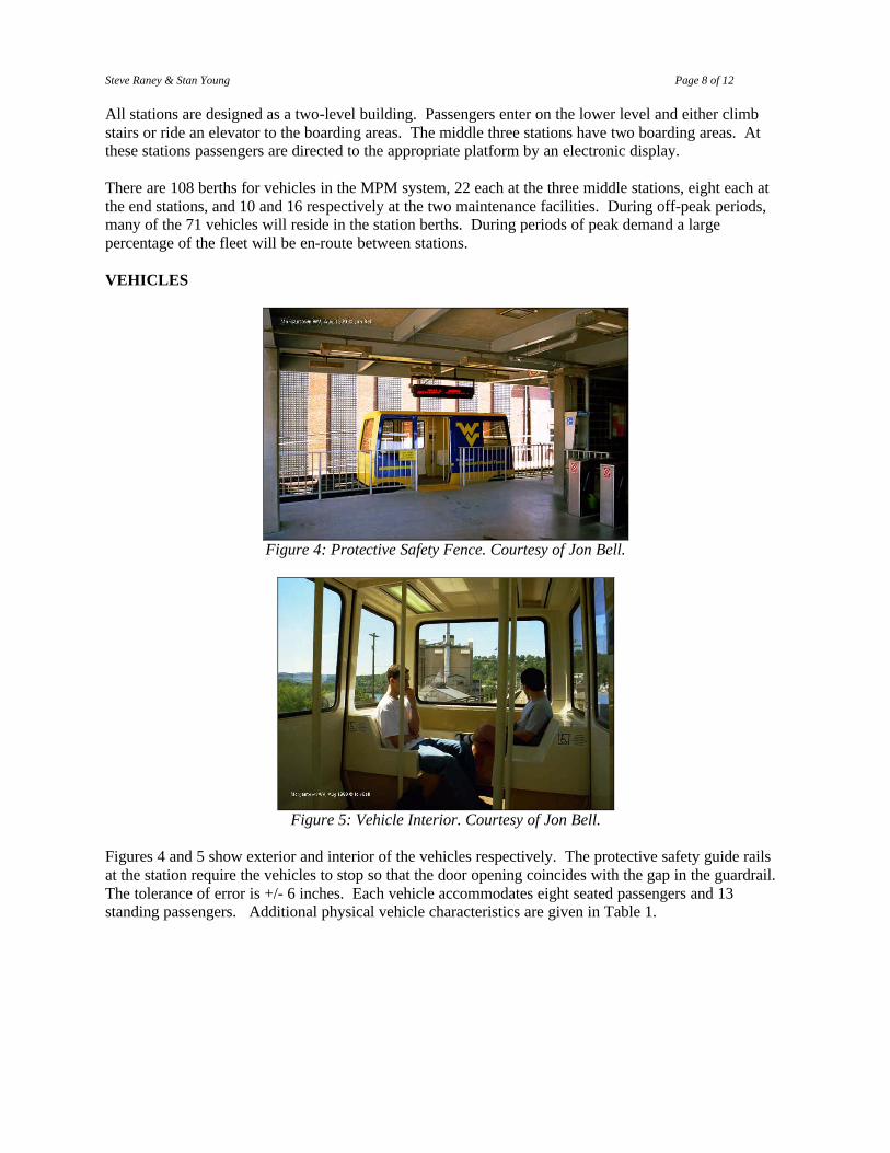
Figure 5: Vehicle Interior. Courtesy of Jon Bell.
Figures 4 and 5 show exterior and interior of the vehicles respectively. The protective safety guide rails at the station require the vehicles to stop so that the door opening coincides with the gap in the guardrail. The tolerance of error is +/- 6 inches. Each vehicle accommodates eight seated passengers and 13 standing passengers. Additional physical vehicle characteristics are given in Table 1.
Steve Raney & Stan Young Page 9 of 12
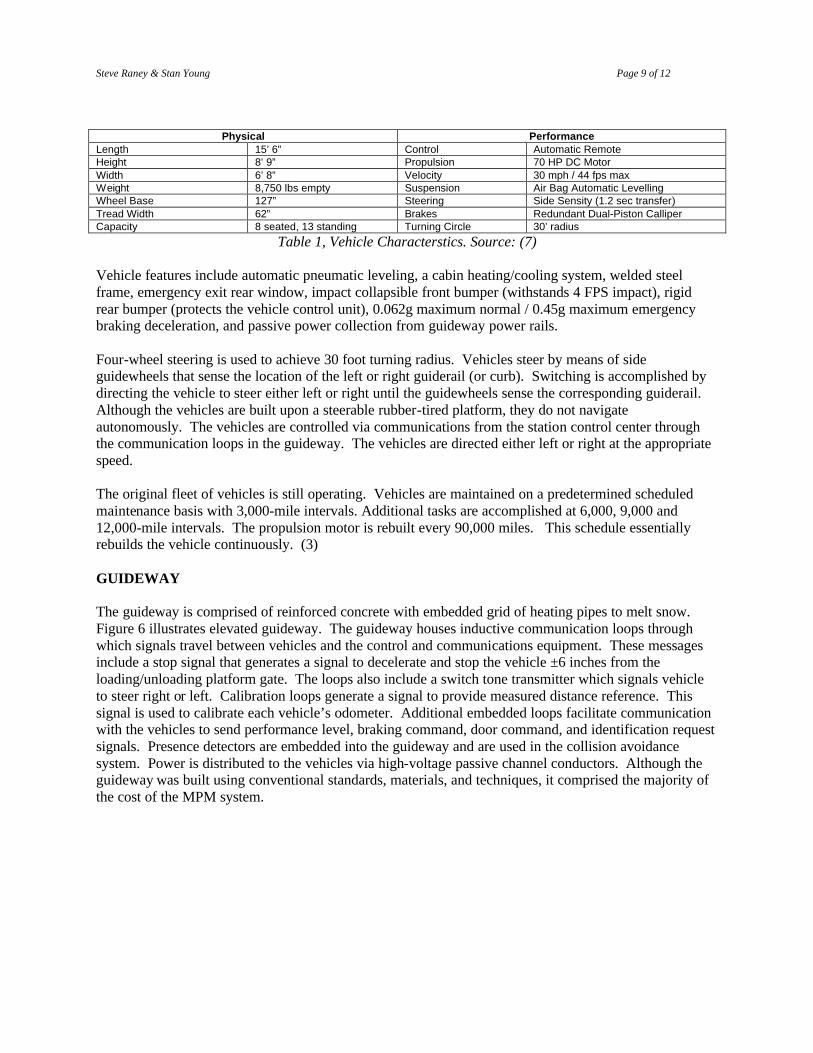
Physical Performance Length 15’ 6” Control Automatic Remote Height 8’ 9” Propulsion 70 HP DC Motor Width 6’ 8” Velocity 30 mph / 44 fps max Weight 8,750 lbs empty Suspension Air Bag Automatic Levelling Wheel Base 127” Steering Side Sensity (1.2 sec transfer) Tread Width 62” Brakes Redundant Dual-Piston Calliper Capacity 8 seated, 13 standing Turning Circle 30’ radius
Table 1, Vehicle Characterstics. Source: (7) Vehicle features include automatic pneumatic leveling, a cabin heating/cooling system, welded steel frame, emergency exit rear window, impact collapsible front bumper (withstands 4 FPS impact), rigid rear bumper (protects the vehicle control unit), 0.062g maximum normal / 0.45g maximum emergency braking deceleration, and passive power collection from guideway power rails. Four-wheel steering is used to achieve 30 foot turning radius. Vehicles steer by means of side guidewheels that sense the location of the left or right guiderail (or curb). Switching is accomplished by directing the vehicle to steer either left or right until the guidewheels sense the corresponding guiderail. Although the vehicles are built upon a steerable rubber-tired platform, they do not navigate autonomously. The vehicles are controlled via communications from the station control center through the communication loops in the guideway. The vehicles are directed either left or right at the appropriate speed. The original fleet of vehicles is still operating. Vehicles are maintained on a predetermined scheduled maintenance basis with 3,000-mile intervals. Additional tasks are accomplished at 6,000, 9,000 and 12,000-mile intervals. The propulsion motor is rebuilt every 90,000 miles. This schedule essentially rebuilds the vehicle continuously. (3) GUIDEWAY The guideway is comprised of reinforced concrete with embedded grid of heating pipes to melt snow. Figure 6 illustrates elevated guideway. The guideway houses inductive communication loops through which signals travel between vehicles and the control and communications equipment. These messages include a stop signal that generates a signal to decelerate and stop the vehicle ±6 inches from the loading/unloading platform gate. The loops also include a switch tone transmitter which signals vehicle to steer right or left. Calibration loops generate a signal to provide measured distance reference. This signal is used to calibrate each vehicle’s odometer. Additional embedded loops facilitate communication with the vehicles to send performance level, braking command, door command, and identification request signals. Presence detectors are embedded into the guideway and are used in the collision avoidance system. Power is distributed to the vehicles via high-voltage passive channel conductors. Although the guideway was built using conventional standards, materials, and techniques, it comprised the majority of the cost of the MPM system.

Steve Raney & Stan Young Page 10 of 12
Figure 6, Two-way, elevated, heated guideway. Photo from
http://faculty.washington.edu/~jbs/itrans/morg.htm. CONTROL SYSTEM The central control concept is based on the moving slot scheme. Imaginary numbered slots, 15 seconds apart, travel around the main guideway. Vehicles may only travel within one of these moving slots, with tolerance of +/- 1.1 seconds. In practice, expected vehicle position is checked against actual position at presence detectors. Once a loaded vehicle’s doors close, central control allocates a numbered slot to the vehicle. Acceleration from the station to the merge point with the main guideway is timed precisely so that the vehicle enters the main guideway at cruising speed within its designated moving slot. An occupied slot may be allocated to a waiting vehicle if the current vehicle plans to exit the main guideway before the loaded, in-station vehicle merges onto the main guideway. System operators are alerted when any vehicle positions are out of tolerance. Because portions of the main guideway speed vary between 22, 33, and 44 FPS, the distance between moving slots varies while the time remains constant. Empty vehicle management is an important aspect of the control system. In demand mode, vehicle demand at each station is estimated based on current passenger requests and past travel patterns. When a station shortfall is detected, empty vehicles are routed to the deficit station from surplus stations. At surplus stations, vehicles are first filled with any waiting passengers before departing for the deficit station. The minimum vehicle demand for each station platform is two, representing a policy of always having two available vehicles per platform. The control system is divided into four parts: central, station, vehicle, and guideway. Central control collects destination service requests and distributes commands to the stations, including allocation of moving slots. 2400 bps modems link central control with stations. Station control processes rider destination requests, manages passenger displays, tracks vehicle status including door closing, and controls vehicle movement (speed, smooth stop in channel berth, switching – steer left or steer right, position calibration). The vehicle control unit responds to station commands to operate motor, brakes, steering, and doors. The guideway houses inductive loops for the vehicle control unit antennae. Vehicles have one send antenna and one receive antenna. Inductive communication message types include: switching, stopping, and door operations. The central control system features a large control room with 32 surveillance monitors, multiple computer consoles, and a mimic display that depicts the guideway, tracking vehicles relative to each presence detector. A three-person crew operates the control system. A flexible voice communication system assists the crew. A PA system provides one-way communication to station platforms. UHF radio provides a two-way link to vehicles and to maintenance personnel. Station telephones also enable two-way communication with the control room.

Steve Raney & Stan Young Page 11 of 12
REDUNDANT SAFETY SYSTEMS MPM is designed for failsafe operation. A major component failure results in a graceful system stop, whereby all vehicles immediately slow down until they stop, and this stop occurs without vehicles crashing. Table 2 details redundant systems.
Item Redundant System Comment Control/communications power Uninterruptible power supply (UPS) Station lighting/surveillance power Standby generator Central computer Backup PC with automatic switchover Station computers Backup PCs with automatic switchover Central control system Humans monitor and can override "Moving point" control system Collision Avoidance System Safe block system independently verifies safe distance between
vehicles, using a second set of presence detectors.
Brakes Redundant 4 wheel disc brakes Tandem piston actuators w/ indep hydraulics per caliper Brakes Parking brakes Actuate when normal brake hydraulic pressure drops Presence detectors Redundant presence detectors Successful switching detection Vehicle validates guideway's check Vehicle speed control "High speed enable" guideway magnets Only in special guideway segments can vehicles go fast. Tires Second air chamber prevents punctures On-board vehicle control hardware Redundant hardware and safety checks
Table 2: Redundant Safety Systems (2) POWER SUBSYSTEM 23kV, three-phase, 60-Hertz power comes from the utility company and is distributed to the guideway and stations. For the guideway power rails, incoming power is converted to 575 VAC, three phase, delta power at three points on the guideway. Passenger stations received 480/277 VAC, three-phase power for heating, lighting, etc. OPERATIONS MPM current operates at between 98% and 99% availability. The total staff is 48 at present. Operation staff includes a manager, four supervisors and five operators. The maintenance staff includes a manager, two supervisors and 26 technicians. Support personnel include three engineers, three stores personnel and two business people. (3) The system has had a history of maintenance challenges. The original DEC PDP 11 minicomputers were discontinued, resulting in spare parts shortages. The DEC computer hardware was replaced by Dell PCs in 1999 with an accompanying port of the assembly language software to the C language. Before the port to the C programming language, the control software consisted of 75,000 lines of PDP-11 assembly language code. Guideway snow-melting heating piping had to be replaced. Power rail had to be replaced. The problems Morgantown faced with obsolescence provide an important lesson for today’s AGRT developers. (8,9,10) FUTURE DIRECTIONS For the Morgantown system, the University and community are actively seeking a $80 million system expansion. (11) The recent Kansas State University (KSU) preliminary investigation of a campus automated small vehicle transit system resulted in a "scanning tour" of the Morgantown system. Lessons learned from the tour helped to inform the KSU study. (11)

Steve Raney & Stan Young Page 12 of 12
ACKNOWLEDGEMENTS An early version of this paper was funded by the San Francisco Bay Area Rapid Transit District's (BART) Advanced Research and Development Group, as part of their Group Rapid Transit Investigative Study. BART's Advanced R&D Manager, Gene Nishinaga, worked on the original Morgantown system while an engineer at Boeing. FHWA and Kansas DOT funded a June 2004 trip to Morgantown by Stan Young and University of Kansas officials. Morgantown People Mover Systems Engineering Manager Robert Hendershot coordinated activities on his side. Thanks to Larry Fabian and Jerry Schneider for assistance in compiling Morgantown "firsts." REFERENCES
1. Tom Gibson, Still in a Class of Its Own, Progressive Engineer, March 2002, http://www.progressiveengineer.com/PEWebBackissues2002/PEWeb%2024%20Mar%2002-2/PRT.htm .
2. Morgantown Personal Rapid Transit System, System Operation Description Manual, M-PRT-1-1. Original version by Boeing Aerospace, 1975, updated since by Robert Hendershot, Morgantown PRT Systems Engineer. http://www.cities21.org/MPMsysOp.pdf.
3. Conversation and e-mail correspondence with Robert Hendershot, Systems Engineering Manager, Morgantown Personal Rapid Transit.
4. Conversation with James Hatcher, Systems Programmer, Morgantown Personal Rapid Transit. 5. Earle Andrews, Automated People Movers in the U.S.A., undated powerpoint-like presentation by
Earle Andrews, president of WVU Board of Regents. 6. Wayne D. Cottrell, Study of Morgantown's Transit Patrons, TRB '05. 7. T.S. Jones, A Comparison of Two Urban People Mover Systems – Morgantown, West Virginia
and Kobe, Japan; Proceedings of the Sixth ASCE International Conference on Automated People Movers, 1997, page 168-182
8. Ronald D. Dangas and Robert Bates, The Morgantown Personal Rapid Transit System – An Update. Proceedings of the Sixth ASCE International Conference on Automated People Movers, 1997, page 156-167.
9. Samy Elias, Edward Neuman, Wafik Iskander. Impact of People Movers on Travel: Morgantown – A Case Study, Transportation Research Record 882, 1982.
10. William J. Sproule and Edward Neumann. The Morgantown PRT: It Is Still Running at West Virginia University, Journal of Advanced Transportation, 25:3, 269-280 (Winter, 1991).
11. Stanley Ernest Young, "Back to the Future" : Key findings of the Morgantown, West Virginia scanning tour, TRB '05.
LIST OF TABLES AND FIGURES Figure 1: Morgantown Alignment Figure 2: Towers Station Design Figure 3: Engineering Station Figure 4: Protective Safety Fence. Courtesy of Jon Bell. Figure 5: Vehicle Interior. Courtesy of Jon Bell. Figure 6: Two-way, elevated, heated guideway Table 1: Vehicle Characterstics Table 2: Redundant Safety Systems