Morehouse - Squarespacemhforce.squarespace.com/s/ASTM-E74-and-Uncertainty-Calculation... · This...
48
1 Morehouse
-
Upload
nguyenduong -
Category
Documents
-
view
225 -
download
2
Transcript of Morehouse - Squarespacemhforce.squarespace.com/s/ASTM-E74-and-Uncertainty-Calculation... · This...

1
Morehouse

Edward Lane, Morehouse Instrument Company
1742 Sixth Ave
York, PA 17403
PH: 717-843-0081 web: www.mhforce.com
sales: [email protected]
2
Morehouse
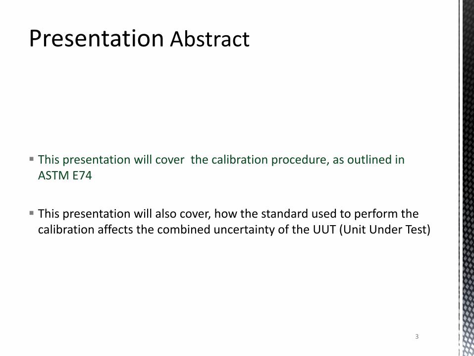
This presentation will cover the calibration procedure, as outlined in ASTM E74
This presentation will also cover, how the standard used to perform the calibration affects the combined uncertainty of the UUT (Unit Under Test)
3
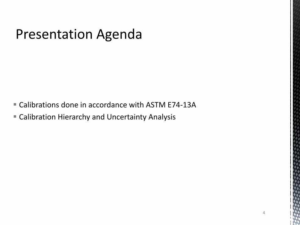
Calibrations done in accordance with ASTM E74-13A
Calibration Hierarchy and Uncertainty Analysis
4

5
Morehouse
6
By the end of this presentation, you should be able to
Understand some of the ASTM E74-13a Standard
Have the resources to calculate an expanded uncertainty for any device calibrated in accordance with ASTM E74-13a
7
8
• A2LA Policy R205 - A2LA Policy on Measurement Uncertainty in Calibration
• A2LA Policy R205 states
• “Every measurement uncertainty shall take into consideration the following standard contributors, even in the cases where they are determined to be insignificant, and documentation of the consideration shall be made:”
9
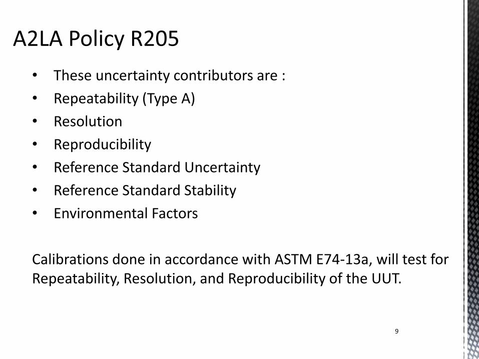
• These uncertainty contributors are :
• Repeatability (Type A)
• Resolution
• Reproducibility
• Reference Standard Uncertainty
• Reference Standard Stability
• Environmental Factors
Calibrations done in accordance with ASTM E74-13a, will test for Repeatability, Resolution, and Reproducibility of the UUT.
Calibration is the comparison of an unknown (typically referred to as the
Unit Under Test or UUT) to a device known within a certain error(typically referred to as the Calibration Standard or Reference Standard) for the purpose of characterizing the unknown
• Calibration Standards in regards to ASTM E74 are typically characterized as either Primary or Secondary Standards
10
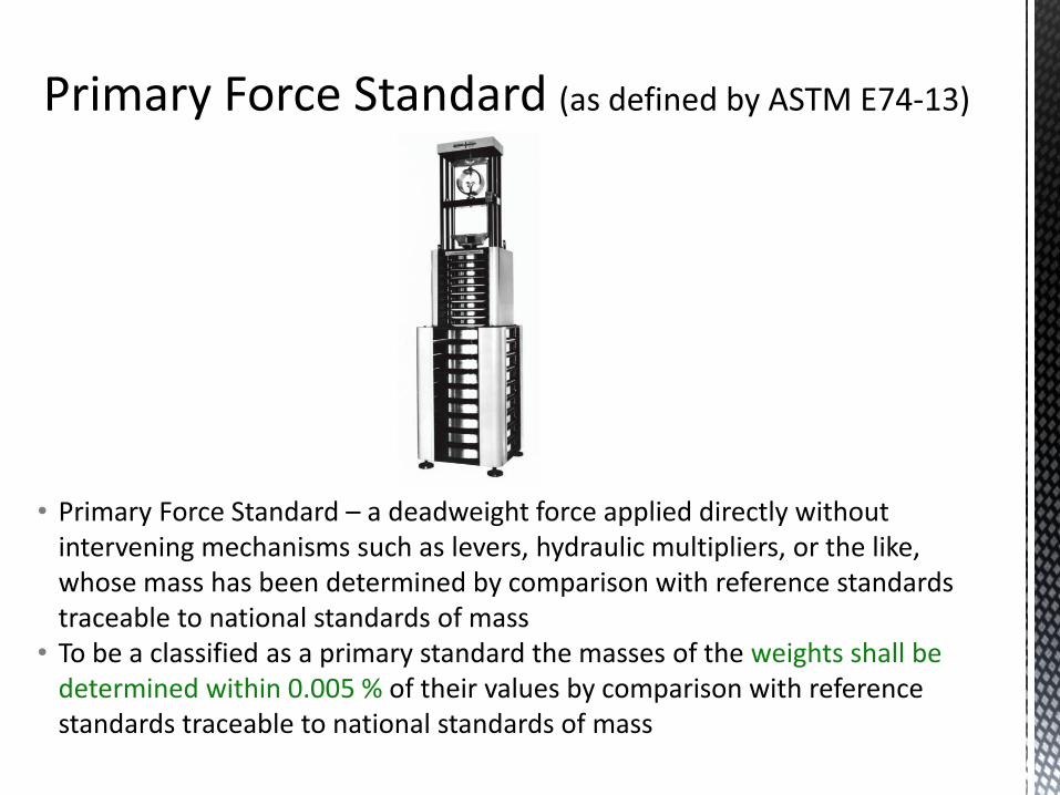
• Primary Force Standard – a deadweight force applied directly without intervening mechanisms such as levers, hydraulic multipliers, or the like, whose mass has been determined by comparison with reference standards traceable to national standards of mass
• To be a classified as a primary standard the masses of the weights shall be determined within 0.005 % of their values by comparison with reference standards traceable to national standards of mass 11
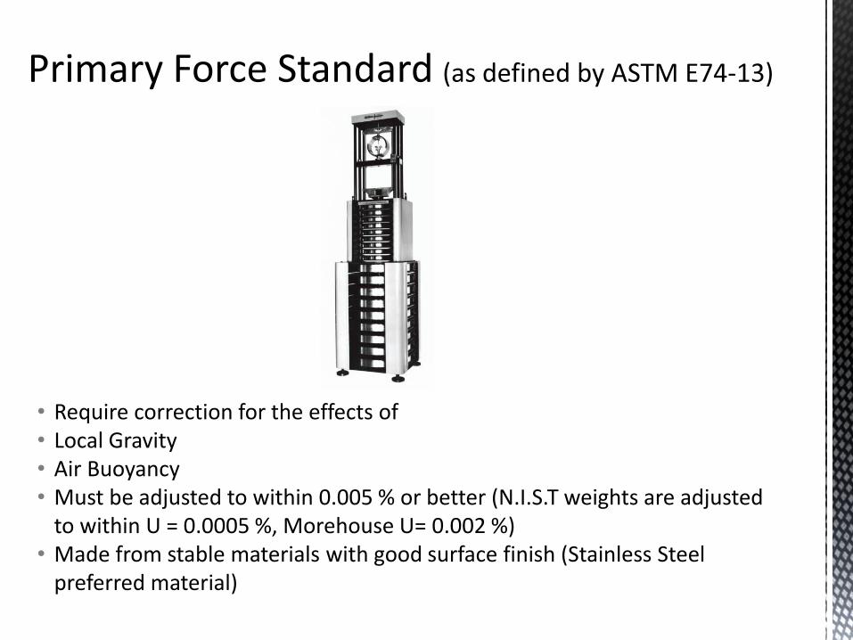
• Require correction for the effects of • Local Gravity • Air Buoyancy • Must be adjusted to within 0.005 % or better (N.I.S.T weights are adjusted
to within U = 0.0005 %, Morehouse U= 0.002 %) • Made from stable materials with good surface finish (Stainless Steel
preferred material) 12
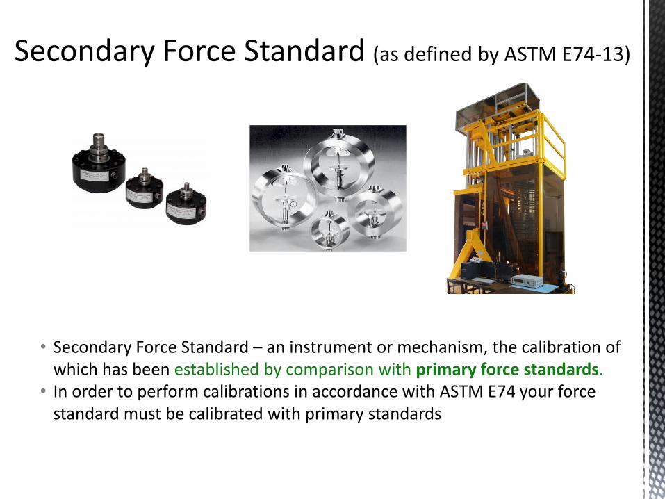
• Secondary Force Standard – an instrument or mechanism, the calibration of which has been established by comparison with primary force standards.
• In order to perform calibrations in accordance with ASTM E74 your force standard must be calibrated with primary standards
13
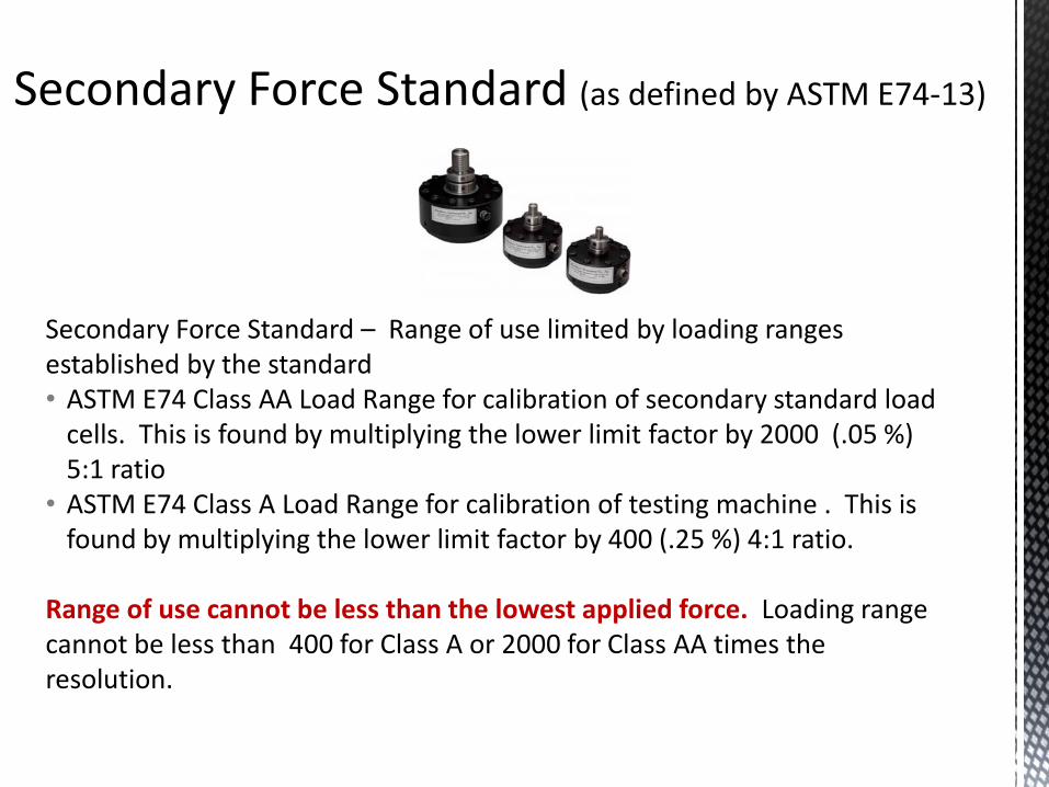
Secondary Force Standard – Range of use limited by loading ranges established by the standard • ASTM E74 Class AA Load Range for calibration of secondary standard load
cells. This is found by multiplying the lower limit factor by 2000 (.05 %) 5:1 ratio
• ASTM E74 Class A Load Range for calibration of testing machine . This is found by multiplying the lower limit factor by 400 (.25 %) 4:1 ratio.
Range of use cannot be less than the lowest applied force. Loading range cannot be less than 400 for Class A or 2000 for Class AA times the resolution.
14
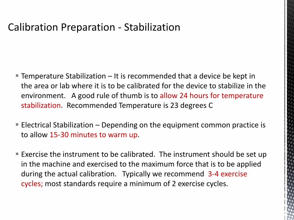
Temperature Stabilization – It is recommended that a device be kept in the area or lab where it is to be calibrated for the device to stabilize in the environment. A good rule of thumb is to allow 24 hours for temperature stabilization. Recommended Temperature is 23 degrees C
Electrical Stabilization – Depending on the equipment common practice is to allow 15-30 minutes to warm up.
Exercise the instrument to be calibrated. The instrument should be set up in the machine and exercised to the maximum force that is to be applied during the actual calibration. Typically we recommend 3-4 exercise cycles; most standards require a minimum of 2 exercise cycles.
15
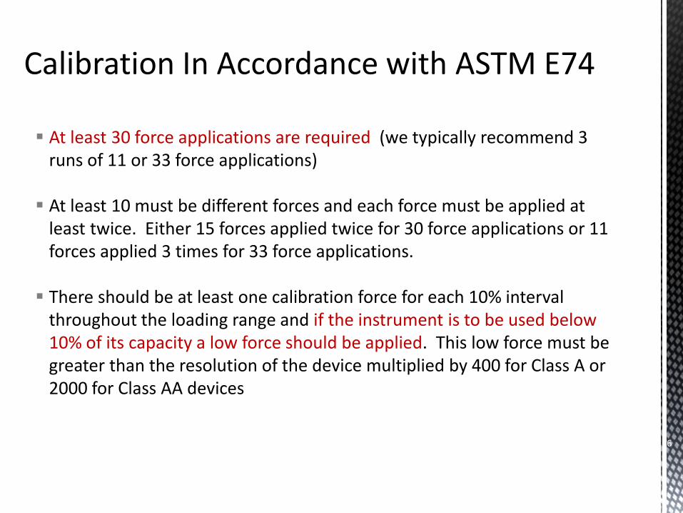
At least 30 force applications are required (we typically recommend 3 runs of 11 or 33 force applications)
At least 10 must be different forces and each force must be applied at least twice. Either 15 forces applied twice for 30 force applications or 11 forces applied 3 times for 33 force applications.
There should be at least one calibration force for each 10% interval throughout the loading range and if the instrument is to be used below 10% of its capacity a low force should be applied. This low force must be greater than the resolution of the device multiplied by 400 for Class A or 2000 for Class AA devices
16
17
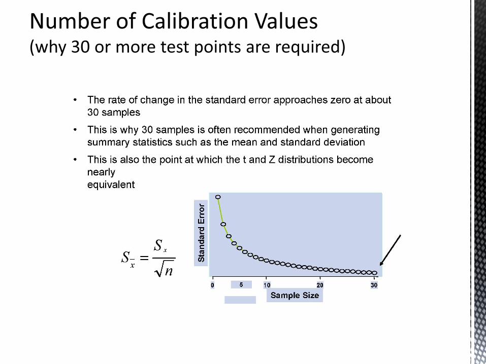
30 +points reduces standard measurement error
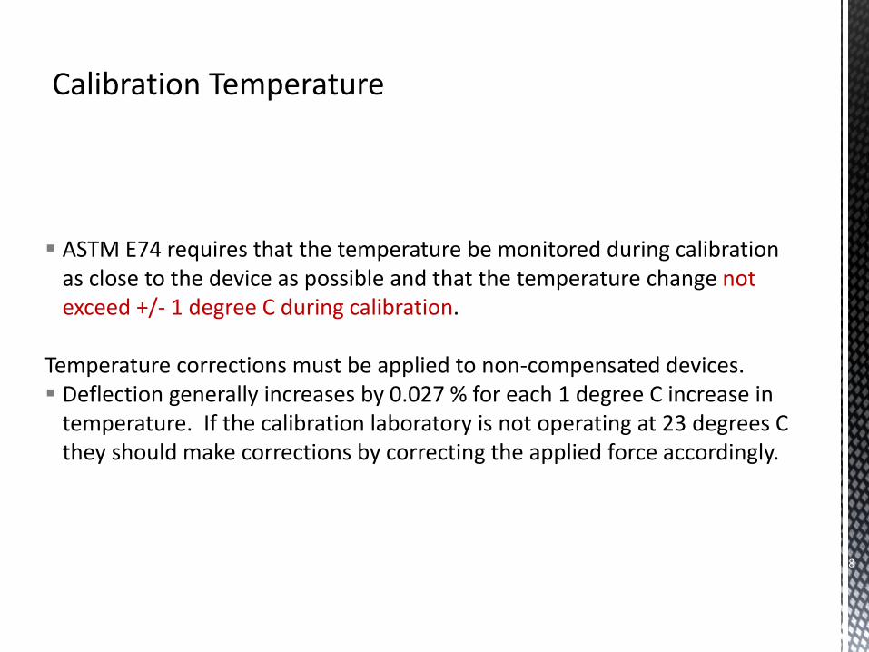
ASTM E74 requires that the temperature be monitored during calibration as close to the device as possible and that the temperature change not exceed +/- 1 degree C during calibration.
Temperature corrections must be applied to non-compensated devices. Deflection generally increases by 0.027 % for each 1 degree C increase in
temperature. If the calibration laboratory is not operating at 23 degrees C they should make corrections by correcting the applied force accordingly.
18
Randomization of Loading Conditions Shift or rotate the UUT in the calibration machine before repeating any
series of forces (suggestion is to rotate 0, 120 and 240 degrees)
For Tension and Compression calibration, intersperse the loadings. Be sure to re-exercise the UUT prior to any change in setup.
Zero Return during calibration - This is lab-dependent and it is recommended that no more than 5 forces be applied before return to zero.
19
Deflection calculation Methods
Method B Deflection readings should be calculated as the difference between readings at the applied force and the average or interpolated zero force readings before and after the applied force readings.
Method A Deflection readings are calculated as the difference between the deflection at the applied force and the initial deflection at zero force.
20
LOAD REVERSAL OR DESCENDING LOADING
If a force measuring device is to be used to measure forces during decreasing load sequences, then it must be calibrated in this manner.
Separate calibration curves can be used for Ascending values and Descending Values
A combined curve may also be used though the STD DEV of the combined curve will be much higher than using separate curves.
21
Criteria for Use of Higher Degree Curve Fits Resolution must exceed 50,000 counts An F distribution test is used to determine the appropriate best degree of
fit (instructions for this test can be found in the Annex A1 of the ASTM E74 Standard)
The Standard deviation for the established curve fit is calculated as before using all the individual deflection values
22
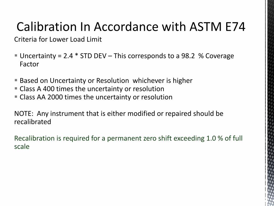
Criteria for Lower Load Limit Uncertainty = 2.4 * STD DEV – This corresponds to a 98.2 % Coverage
Factor
Based on Uncertainty or Resolution whichever is higher Class A 400 times the uncertainty or resolution Class AA 2000 times the uncertainty or resolution
NOTE: Any instrument that is either modified or repaired should be recalibrated Recalibration is required for a permanent zero shift exceeding 1.0 % of full scale
23
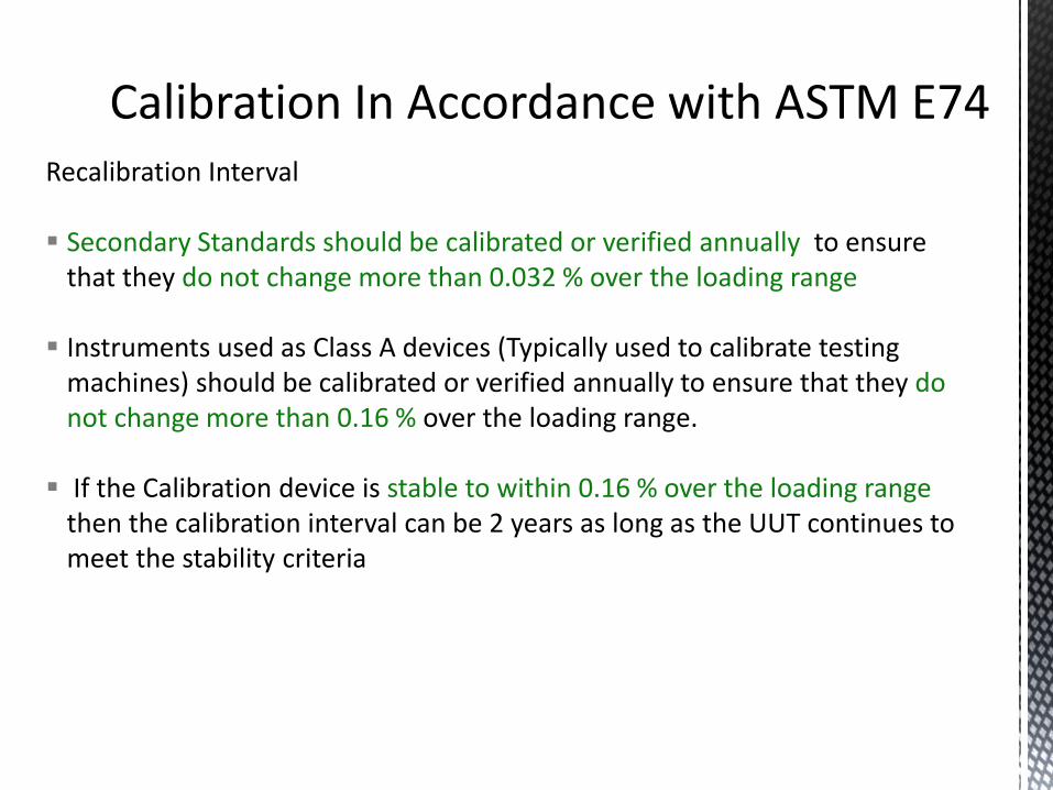
Recalibration Interval Secondary Standards should be calibrated or verified annually to ensure
that they do not change more than 0.032 % over the loading range
Instruments used as Class A devices (Typically used to calibrate testing machines) should be calibrated or verified annually to ensure that they do not change more than 0.16 % over the loading range.
If the Calibration device is stable to within 0.16 % over the loading range then the calibration interval can be 2 years as long as the UUT continues to meet the stability criteria
24
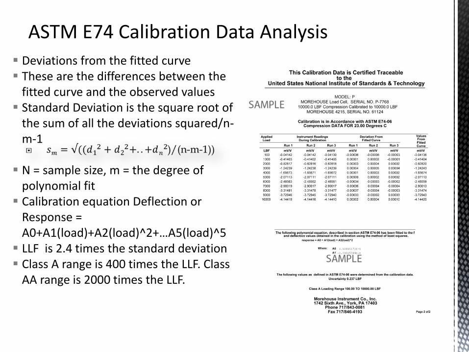
Deviations from the fitted curve These are the differences between the
fitted curve and the observed values Standard Deviation is the square root of
the sum of all the deviations squared/n-m-1
N = sample size, m = the degree of polynomial fit
Calibration equation Deflection or Response = A0+A1(load)+A2(load)^2+…A5(load)^5
LLF is 2.4 times the standard deviation Class A range is 400 times the LLF. Class
AA range is 2000 times the LLF.
25
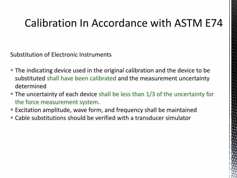
Substitution of Electronic Instruments The indicating device used in the original calibration and the device to be
substituted shall have been calibrated and the measurement uncertainty determined
The uncertainty of each device shall be less than 1/3 of the uncertainty for the force measurement system.
Excitation amplitude, wave form, and frequency shall be maintained Cable substitutions should be verified with a transducer simulator
26
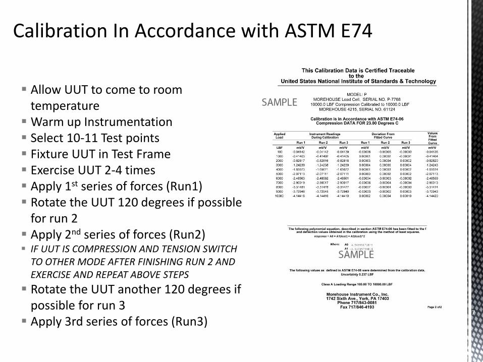
Allow UUT to come to room temperature
Warm up Instrumentation Select 10-11 Test points Fixture UUT in Test Frame Exercise UUT 2-4 times Apply 1st series of forces (Run1) Rotate the UUT 120 degrees if possible
for run 2 Apply 2nd series of forces (Run2) IF UUT IS COMPRESSION AND TENSION SWITCH
TO OTHER MODE AFTER FINISHING RUN 2 AND EXERCISE AND REPEAT ABOVE STEPS
Rotate the UUT another 120 degrees if possible for run 3
Apply 3rd series of forces (Run3) 27
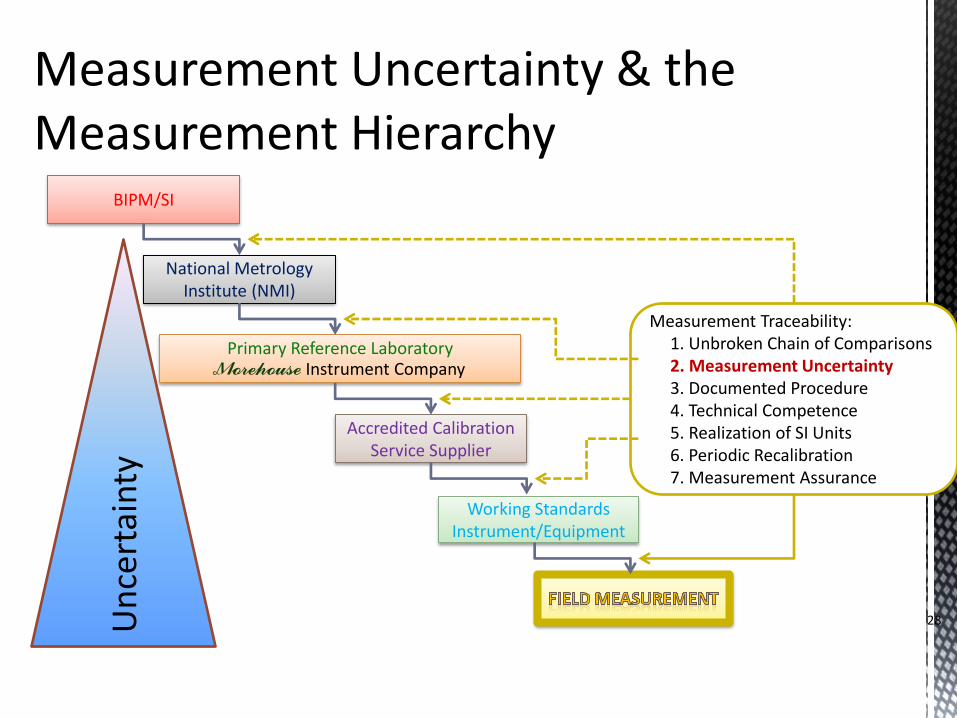
BIPM/SI
National Metrology Institute (NMI)
Primary Reference Laboratory
Morehouse Instrument Company
Accredited Calibration Service Supplier
Working Standards Instrument/Equipment
Measurement Traceability: 1. Unbroken Chain of Comparisons 2. Measurement Uncertainty 3. Documented Procedure 4. Technical Competence 5. Realization of SI Units 6. Periodic Recalibration 7. Measurement Assurance
Un
cert
ain
ty
28
29
NMI
Primary Standards
Accredited Cal. Lab
Working Standards
Field Measurement
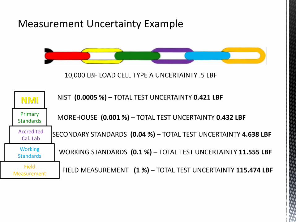
NIST (0.0005 %) – TOTAL TEST UNCERTAINTY 0.421 LBF
10,000 LBF LOAD CELL TYPE A UNCERTAINTY .5 LBF
MOREHOUSE (0.001 %) – TOTAL TEST UNCERTAINTY 0.432 LBF
SECONDARY STANDARDS (0.04 %) – TOTAL TEST UNCERTAINTY 4.638 LBF
WORKING STANDARDS (0.1 %) – TOTAL TEST UNCERTAINTY 11.555 LBF
FIELD MEASUREMENT (1 %) – TOTAL TEST UNCERTAINTY 115.474 LBF
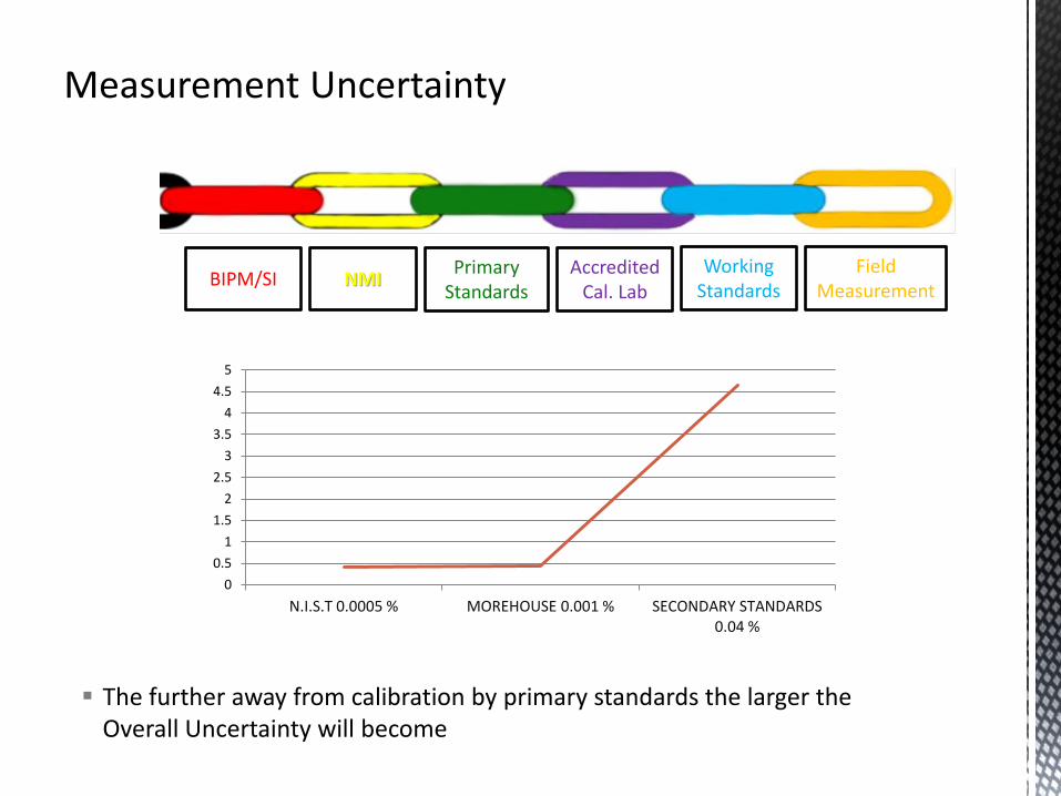
The further away from calibration by primary standards the larger the Overall Uncertainty will become 30
BIPM/SI NMI Primary
Standards Accredited
Cal. Lab Working
Standards Field
Measurement
0
0.5
1
1.5
2
2.5
3
3.5
4
4.5
5
N.I.S.T 0.0005 % MOREHOUSE 0.001 % SECONDARY STANDARDS 0.04 %
The next example will deal with an uncertainty analysis that is in the ASTM E74-13a standard as an appendix.
Repeatability, Reproducibility, and Resolution are all accounted for in the ASTM E74 uncertainty or LLF (Lower Limit Factor).
31
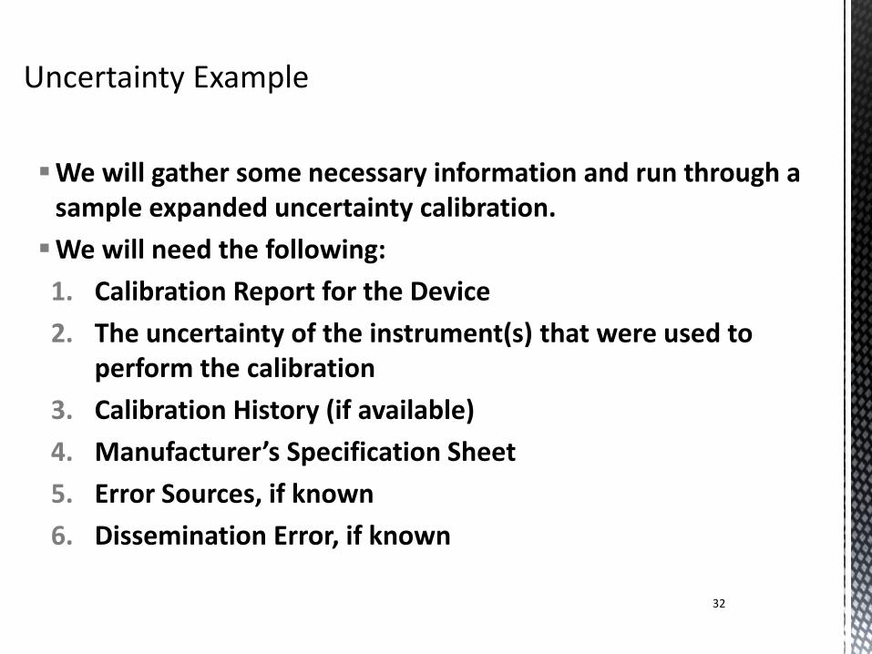
We will gather some necessary information and run through a sample expanded uncertainty calibration.
We will need the following:
1. Calibration Report for the Device
2. The uncertainty of the instrument(s) that were used to perform the calibration
3. Calibration History (if available)
4. Manufacturer’s Specification Sheet
5. Error Sources, if known
6. Dissemination Error, if known
32
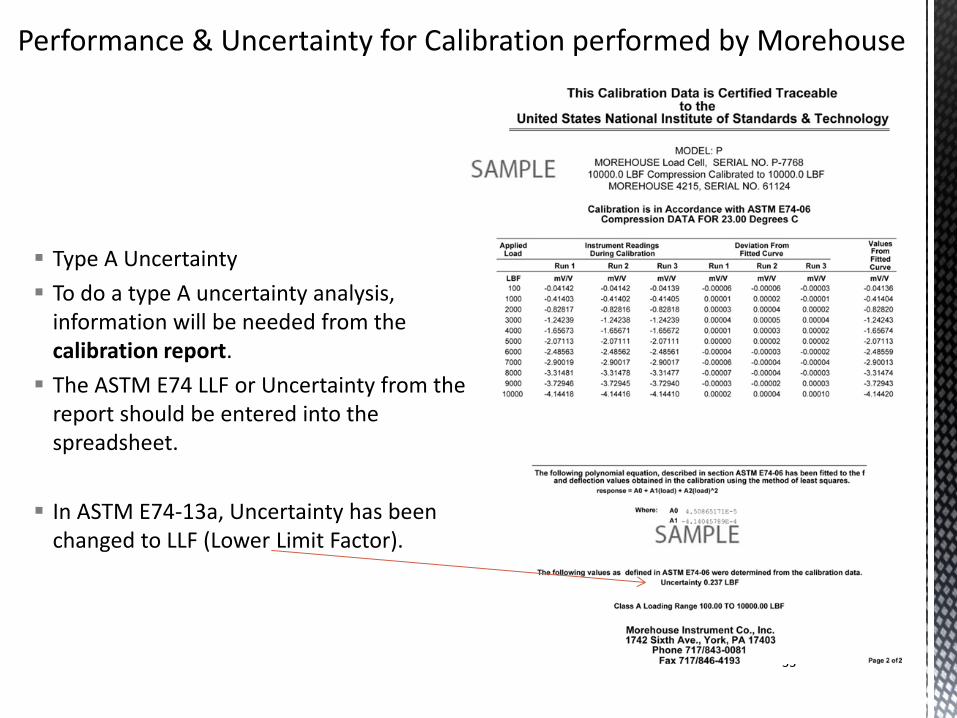
Type A Uncertainty
To do a type A uncertainty analysis, information will be needed from the calibration report.
The ASTM E74 LLF or Uncertainty from the report should be entered into the spreadsheet.
In ASTM E74-13a, Uncertainty has been changed to LLF (Lower Limit Factor).
33
34
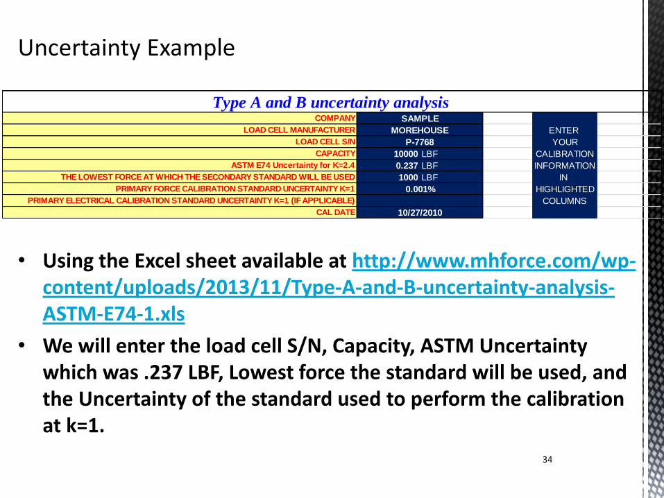
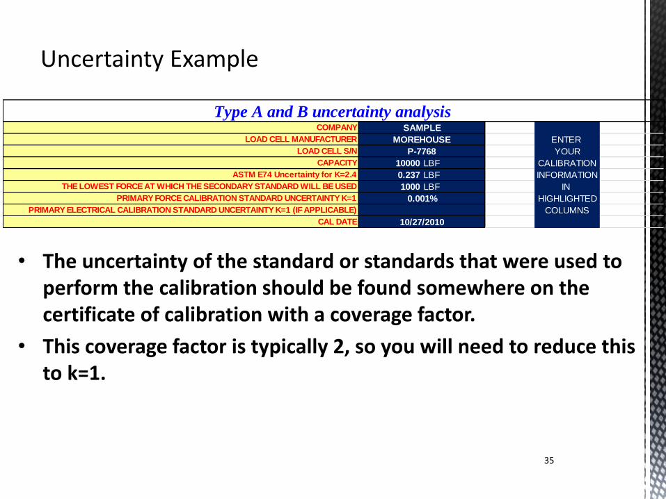
• Using the Excel sheet available at http://www.mhforce.com/wp-content/uploads/2013/11/Type-A-and-B-uncertainty-analysis-ASTM-E74-1.xls
• We will enter the load cell S/N, Capacity, ASTM Uncertainty which was .237 LBF, Lowest force the standard will be used, and the Uncertainty of the standard used to perform the calibration at k=1.
COMPANY
LOAD CELL MANUFACTURER ENTER
LOAD CELL S/N YOUR
CAPACITY 10000 LBF CALIBRATION
ASTM E74 Uncertainty for K=2.4 0.237 LBF INFORMATION
THE LOWEST FORCE AT WHICH THE SECONDARY STANDARD WILL BE USED 1000 LBF IN
PRIMARY FORCE CALIBRATION STANDARD UNCERTAINTY K=1 HIGHLIGHTED
PRIMARY ELECTRICAL CALIBRATION STANDARD UNCERTAINTY K=1 (IF APPLICABLE) COLUMNS
CAL DATE
P-7768
0.001%
10/27/2010
MOREHOUSE
Type A and B uncertainty analysis SAMPLE
35
• The uncertainty of the standard or standards that were used to perform the calibration should be found somewhere on the certificate of calibration with a coverage factor.
• This coverage factor is typically 2, so you will need to reduce this to k=1.
COMPANY
LOAD CELL MANUFACTURER ENTER
LOAD CELL S/N YOUR
CAPACITY 10000 LBF CALIBRATION
ASTM E74 Uncertainty for K=2.4 0.237 LBF INFORMATION
THE LOWEST FORCE AT WHICH THE SECONDARY STANDARD WILL BE USED 1000 LBF IN
PRIMARY FORCE CALIBRATION STANDARD UNCERTAINTY K=1 HIGHLIGHTED
PRIMARY ELECTRICAL CALIBRATION STANDARD UNCERTAINTY K=1 (IF APPLICABLE) COLUMNS
CAL DATE
P-7768
0.001%
10/27/2010
MOREHOUSE
Type A and B uncertainty analysis SAMPLE
36
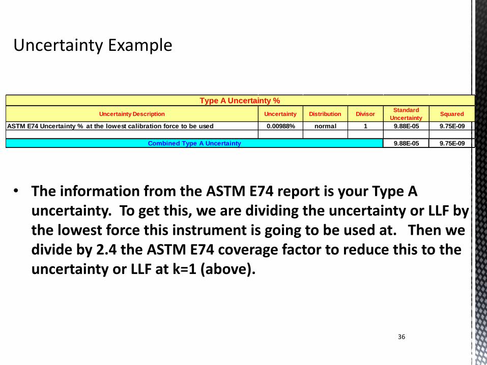
• The information from the ASTM E74 report is your Type A uncertainty. To get this, we are dividing the uncertainty or LLF by the lowest force this instrument is going to be used at. Then we divide by 2.4 the ASTM E74 coverage factor to reduce this to the uncertainty or LLF at k=1 (above).
Uncertainty Description Uncertainty Distribution DivisorStandard
UncertaintySquared
ASTM E74 Uncertainty % at the lowest calibration force to be used 0.00988% normal 1 9.88E-05 9.75E-09
9.88E-05 9.75E-09
Type A Uncertainty %
Combined Type A Uncertainty
37
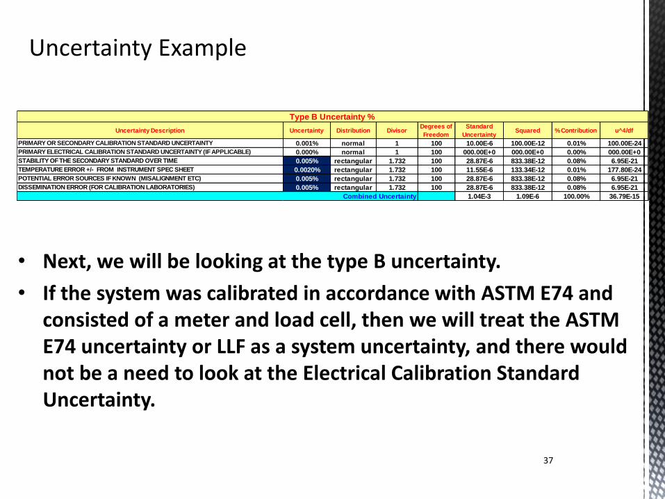
• Next, we will be looking at the type B uncertainty.
• If the system was calibrated in accordance with ASTM E74 and consisted of a meter and load cell, then we will treat the ASTM E74 uncertainty or LLF as a system uncertainty, and there would not be a need to look at the Electrical Calibration Standard Uncertainty.
Uncertainty Description Uncertainty Distribution DivisorDegrees of
Freedom
Standard
UncertaintySquared % Contribution u^4/df
PRIMARY OR SECONDARY CALIBRATION STANDARD UNCERTAINTY 0.001% normal 1 100 10.00E-6 100.00E-12 0.01% 100.00E-24
PRIMARY ELECTRICAL CALIBRATION STANDARD UNCERTAINTY (IF APPLICABLE) 0.000% normal 1 100 000.00E+0 000.00E+0 0.00% 000.00E+0
STABILITY OF THE SECONDARY STANDARD OVER TIME 0.005% rectangular 1.732 100 28.87E-6 833.38E-12 0.08% 6.95E-21
TEMPERATURE ERROR +/- FROM INSTRUMENT SPEC SHEET 0.0020% rectangular 1.732 100 11.55E-6 133.34E-12 0.01% 177.80E-24
POTENTIAL ERROR SOURCES IF KNOWN (MISALIGNMENT ETC) 0.005% rectangular 1.732 100 28.87E-6 833.38E-12 0.08% 6.95E-21
DISSEMINATION ERROR (FOR CALIBRATION LABORATORIES) 0.005% rectangular 1.732 100 28.87E-6 833.38E-12 0.08% 6.95E-21
1.04E-3 1.09E-6 100.00% 36.79E-15
Type B Uncertainty %
Combined Uncertainty
38
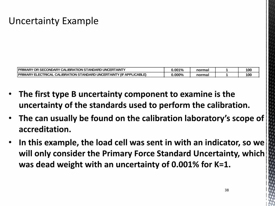
• The first type B uncertainty component to examine is the uncertainty of the standards used to perform the calibration.
• The can usually be found on the calibration laboratory’s scope of accreditation.
• In this example, the load cell was sent in with an indicator, so we will only consider the Primary Force Standard Uncertainty, which was dead weight with an uncertainty of 0.001% for K=1.
PRIMARY OR SECONDARY CALIBRATION STANDARD UNCERTAINTY 0.001% normal 1 100
PRIMARY ELECTRICAL CALIBRATION STANDARD UNCERTAINTY (IF APPLICABLE) 0.000% normal 1 100
39
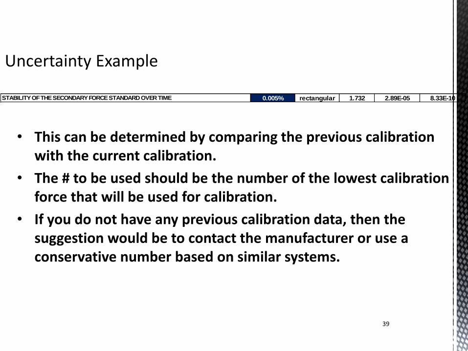
• This can be determined by comparing the previous calibration with the current calibration.
• The # to be used should be the number of the lowest calibration force that will be used for calibration.
• If you do not have any previous calibration data, then the suggestion would be to contact the manufacturer or use a conservative number based on similar systems.
STABILITY OF THE SECONDARY FORCE STANDARD OVER TIME 0.005% rectangular 1.732 2.89E-05 8.33E-10
40
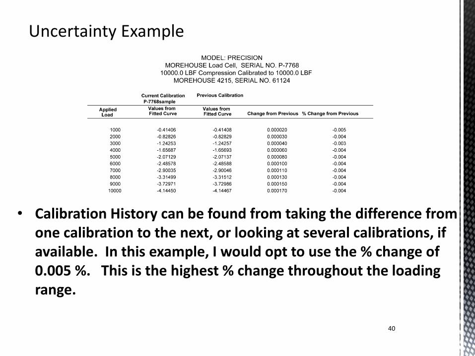
• Calibration History can be found from taking the difference from one calibration to the next, or looking at several calibrations, if available. In this example, I would opt to use the % change of 0.005 %. This is the highest % change throughout the loading range.
41
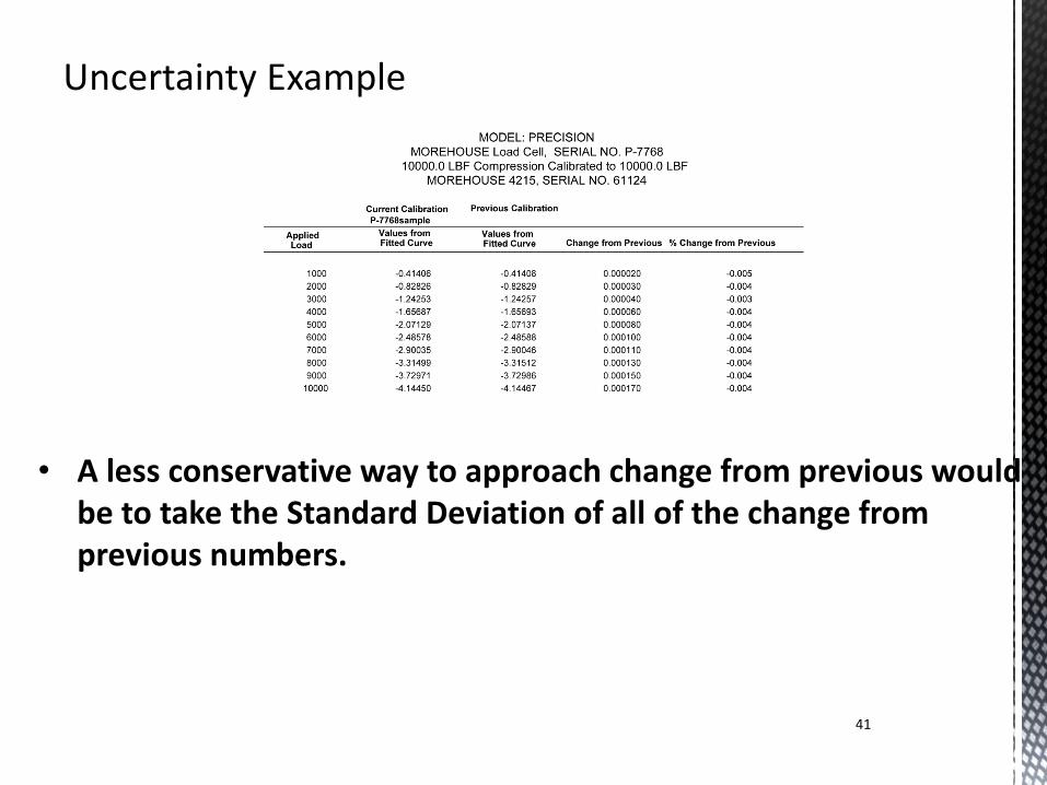
• A less conservative way to approach change from previous would be to take the Standard Deviation of all of the change from previous numbers.
42
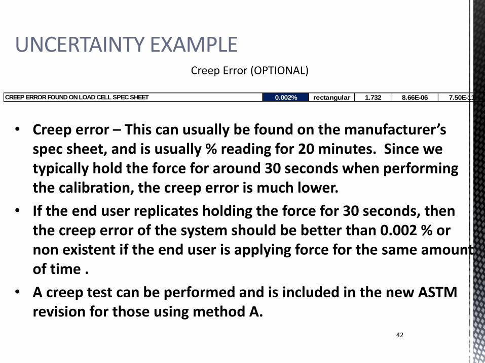
• Creep error – This can usually be found on the manufacturer’s spec sheet, and is usually % reading for 20 minutes. Since we typically hold the force for around 30 seconds when performing the calibration, the creep error is much lower.
• If the end user replicates holding the force for 30 seconds, then the creep error of the system should be better than 0.002 % or non existent if the end user is applying force for the same amount of time .
• A creep test can be performed and is included in the new ASTM revision for those using method A.
CREEP ERROR FOUND ON LOAD CELL SPEC SHEET 0.002% rectangular 1.732 8.66E-06 7.50E-11
UNCERTAINTY EXAMPLE Creep Error (OPTIONAL)
43
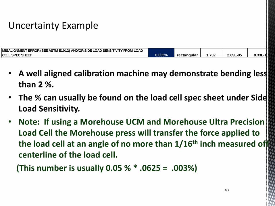
• A well aligned calibration machine may demonstrate bending less than 2 %.
• The % can usually be found on the load cell spec sheet under Side Load Sensitivity.
• Note: If using a Morehouse UCM and Morehouse Ultra Precision Load Cell the Morehouse press will transfer the force applied to the load cell at an angle of no more than 1/16th inch measured off centerline of the load cell.
(This number is usually 0.05 % * .0625 = .003%)
MISALIGNMENT ERROR (SEE ASTM E1012) AND/OR SIDE LOAD SENSITIVITY FROM LOAD
CELL SPEC SHEET 0.005% rectangular 1.732 2.89E-05 8.33E-10
44
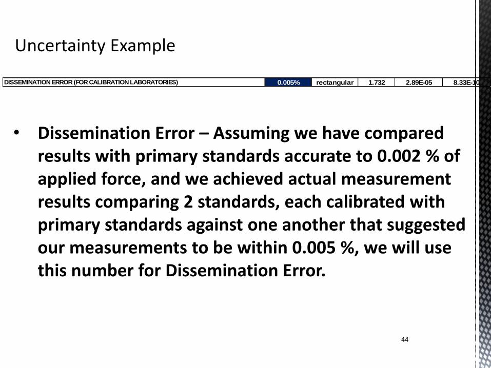
DISSEMINATION ERROR (FOR CALIBRATION LABORATORIES) 0.005% rectangular 1.732 2.89E-05 8.33E-10
• Dissemination Error – Assuming we have compared results with primary standards accurate to 0.002 % of applied force, and we achieved actual measurement results comparing 2 standards, each calibrated with primary standards against one another that suggested our measurements to be within 0.005 %, we will use this number for Dissemination Error.
45
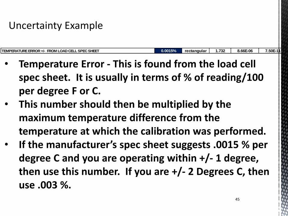
• Temperature Error - This is found from the load cell spec sheet. It is usually in terms of % of reading/100 per degree F or C.
• This number should then be multiplied by the maximum temperature difference from the temperature at which the calibration was performed.
• If the manufacturer’s spec sheet suggests .0015 % per degree C and you are operating within +/- 1 degree, then use this number. If you are +/- 2 Degrees C, then use .003 %.
TEMPERATURE ERROR +/- FROM LOAD CELL SPEC SHEET 0.0015% rectangular 1.732 8.66E-06 7.50E-11
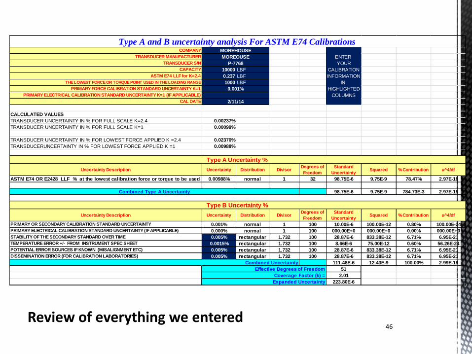
Review of everything we entered 46
COMPANY
TRANSDUCER MANUFACTURER ENTER
TRANSDUCER S/N YOUR
CAPACITY 10000 LBF CALIBRATION
ASTM E74 LLF for K=2.4 0.237 LBF INFORMATION
THE LOWEST FORCE OR TORQUE POINT USED IN THE LOADING RANGE 1000 LBF IN
PRIMARY FORCE CALIBRATION STANDARD UNCERTAINTY K=1 HIGHLIGHTED
PRIMARY ELECTRICAL CALIBRATION STANDARD UNCERTAINTY K=1 (IF APPLICABLE) COLUMNS
CAL DATE
CALCULATED VALUES
TRANSDUCER UNCERTAINTY IN % FOR FULL SCALE K=2.4 0.00237%
TRANSDUCER UNCERTAINTY IN % FOR FULL SCALE K=1 0.00099%
TRANSDUCER UNCERTAINTY IN % FOR LOWEST FORCE APPLIED K =2.4 0.02370%
TRANSDUCERUNCERTAINTY IN % FOR LOWEST FORCE APPLIED K =1 0.00988%
Uncertainty Description Uncertainty Distribution DivisorDegrees of
Freedom
Standard
UncertaintySquared % Contribution u^4/df
ASTM E74 OR E2428 LLF % at the lowest calibration force or torque to be used 0.00988% normal 1 32 98.75E-6 9.75E-9 78.47% 2.97E-18
98.75E-6 9.75E-9 784.73E-3 2.97E-18
Uncertainty Description Uncertainty Distribution DivisorDegrees of
Freedom
Standard
UncertaintySquared % Contribution u^4/df
PRIMARY OR SECONDARY CALIBRATION STANDARD UNCERTAINTY 0.001% normal 1 100 10.00E-6 100.00E-12 0.80% 100.00E-24
PRIMARY ELECTRICAL CALIBRATION STANDARD UNCERTAINTY (IF APPLICABLE) 0.000% normal 1 100 000.00E+0 000.00E+0 0.00% 000.00E+0
STABILITY OF THE SECONDARY STANDARD OVER TIME 0.005% rectangular 1.732 100 28.87E-6 833.38E-12 6.71% 6.95E-21
TEMPERATURE ERROR +/- FROM INSTRUMENT SPEC SHEET 0.0015% rectangular 1.732 100 8.66E-6 75.00E-12 0.60% 56.26E-24
POTENTIAL ERROR SOURCES IF KNOWN (MISALIGNMENT ETC) 0.005% rectangular 1.732 100 28.87E-6 833.38E-12 6.71% 6.95E-21
DISSEMINATION ERROR (FOR CALIBRATION LABORATORIES) 0.005% rectangular 1.732 100 28.87E-6 833.38E-12 6.71% 6.95E-21
111.48E-6 12.43E-9 100.00% 2.99E-18
51
2.01
223.80E-6
Effective Degrees of Freedom
Coverage Factor (k) =
Expanded Uncertainty
2/11/14
Type A Uncertainty %
Combined Type A Uncertainty
Type B Uncertainty %
Combined Uncertainty
Type A and B uncertainty analysis For ASTM E74 Calibrations MOREHOUSE
MOREOUSE
P-7768
0.001%
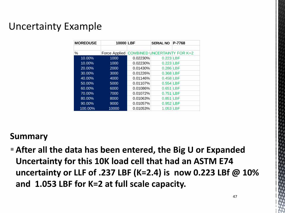
Summary
After all the data has been entered, the Big U or Expanded Uncertainty for this 10K load cell that had an ASTM E74 uncertainty or LLF of .237 LBF (K=2.4) is now 0.223 LBf @ 10% and 1.053 LBF for K=2 at full scale capacity.
47
MOREOUSE 10000 LBF SERIAL NO P-7768
% Force Applied COMBINED UNCERTAINTY FOR K=2
10.00% 1000 0.02230% 0.223 LBF
10.00% 1000 0.02230% 0.223 LBF
20.00% 2000 0.01430% 0.286 LBF
30.00% 3000 0.01226% 0.368 LBF
40.00% 4000 0.01146% 0.458 LBF
50.00% 5000 0.01107% 0.554 LBF
60.00% 6000 0.01086% 0.651 LBF
70.00% 7000 0.01072% 0.751 LBF
80.00% 8000 0.01063% 0.851 LBF
90.00% 9000 0.01057% 0.952 LBF
100.00% 10000 0.01053% 1.053 LBF
This example is just a guideline for calculating expanded uncertainty. The actual uncertainty components in your system may vary.
48