
More Mosaic Madness 15-463: Computational Photography Alexei Efros, CMU, Fall 2011 © Jeffrey Martin...
33
More Mosaic Madness 15-463: Computational Photograph Alexei Efros, CMU, Fall 201 © Jeffrey Martin (jeffrey-martin.com) with a lot of slides stolen from Steve Seitz and Rick Szeliski
-
Upload
gina-bowsher -
Category
Documents
-
view
217 -
download
1
Transcript of More Mosaic Madness 15-463: Computational Photography Alexei Efros, CMU, Fall 2011 © Jeffrey Martin...
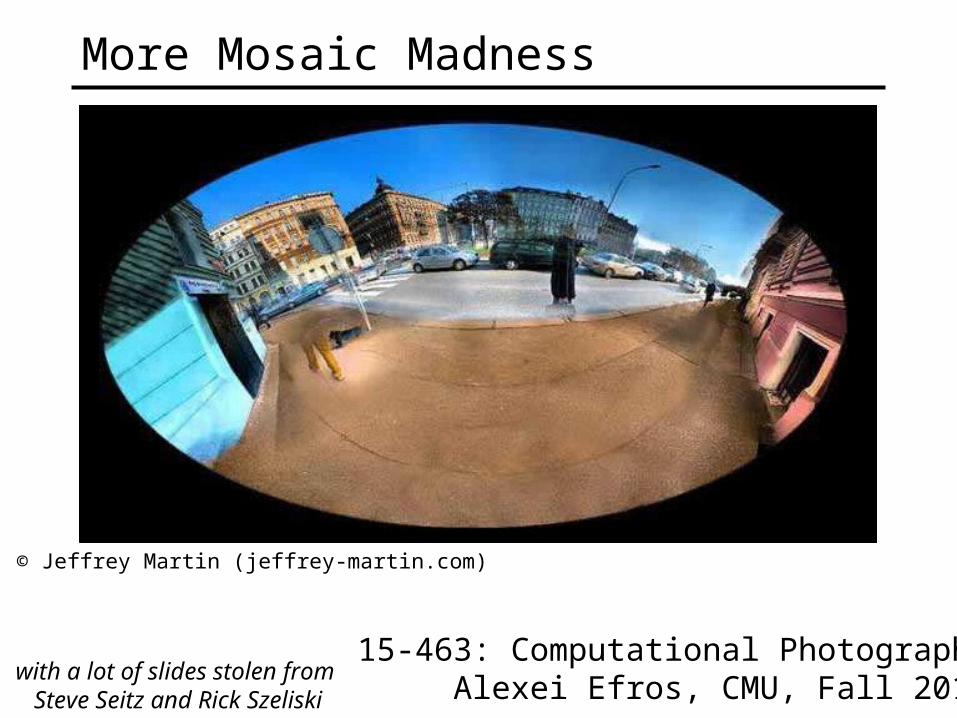
More Mosaic Madness
15-463: Computational PhotographyAlexei Efros, CMU, Fall 2011
© Jeffrey Martin (jeffrey-martin.com)
with a lot of slides stolen from Steve Seitz and Rick Szeliski
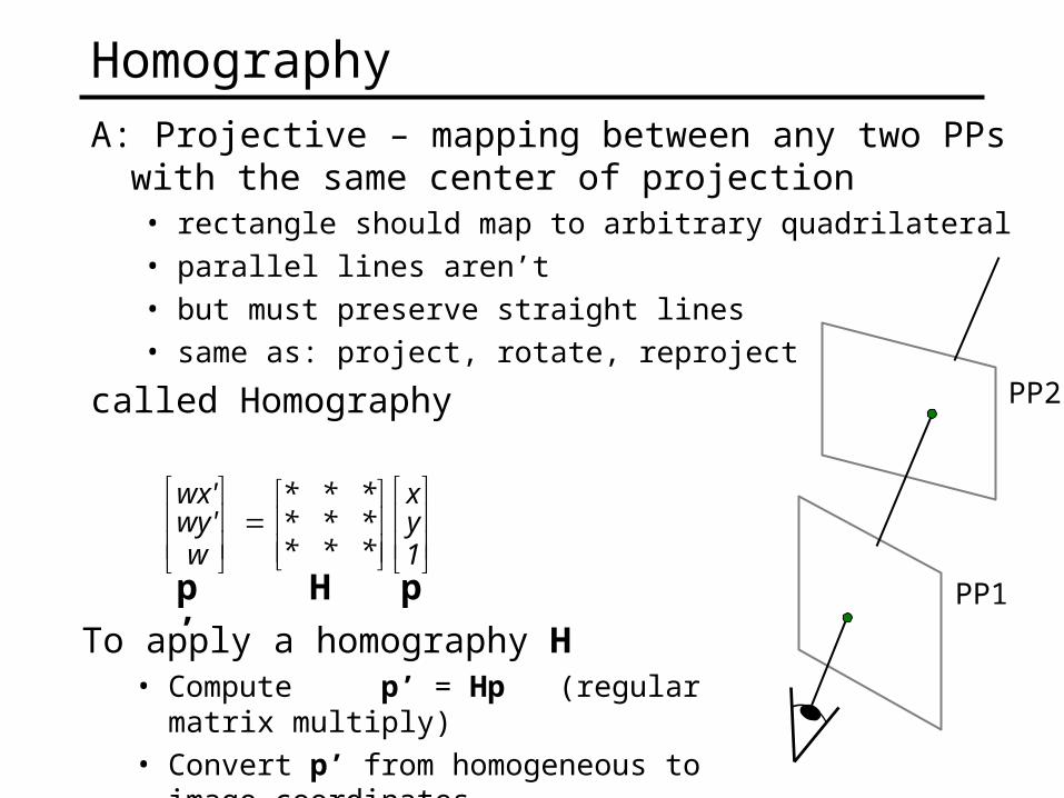
HomographyA: Projective – mapping between any two PPs with the
same center of projection• rectangle should map to arbitrary quadrilateral • parallel lines aren’t• but must preserve straight lines• same as: project, rotate, reproject
called Homography PP2
PP1
1yx
*********
wwy'wx'
H pp’ To apply a homography H
• Compute p’ = Hp (regular matrix multiply)
• Convert p’ from homogeneous to image coordinates
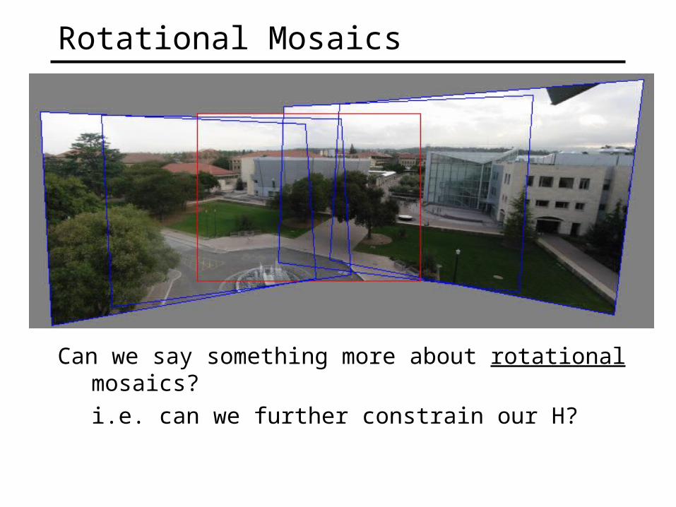
Rotational Mosaics
Can we say something more about rotational mosaics?
i.e. can we further constrain our H?
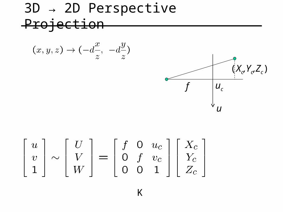
3D → 2D Perspective Projection
u
(Xc,Yc,Zc)
ucf
K
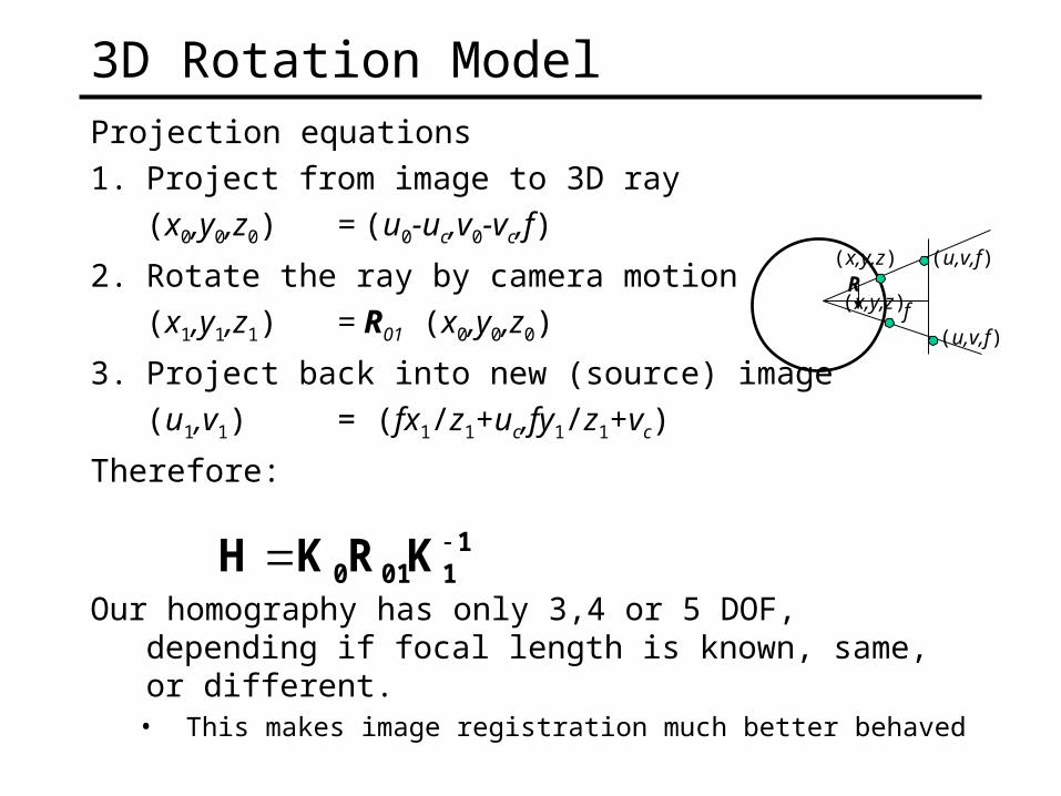
3D Rotation ModelProjection equations
1. Project from image to 3D ray
(x0,y0,z0) = (u0-uc,v0-vc,f)
2. Rotate the ray by camera motion
(x1,y1,z1) = R01 (x0,y0,z0)
3. Project back into new (source) image
(u1,v1) = (fx1/z1+uc,fy1/z1+vc)
Therefore:
Our homography has only 3,4 or 5 DOF, depending if focal length is known, same, or different.
• This makes image registration much better behaved
(u,v,f)(x,y,z)
f(x,y,z)
(u,v,f)
R
11010 KRKH
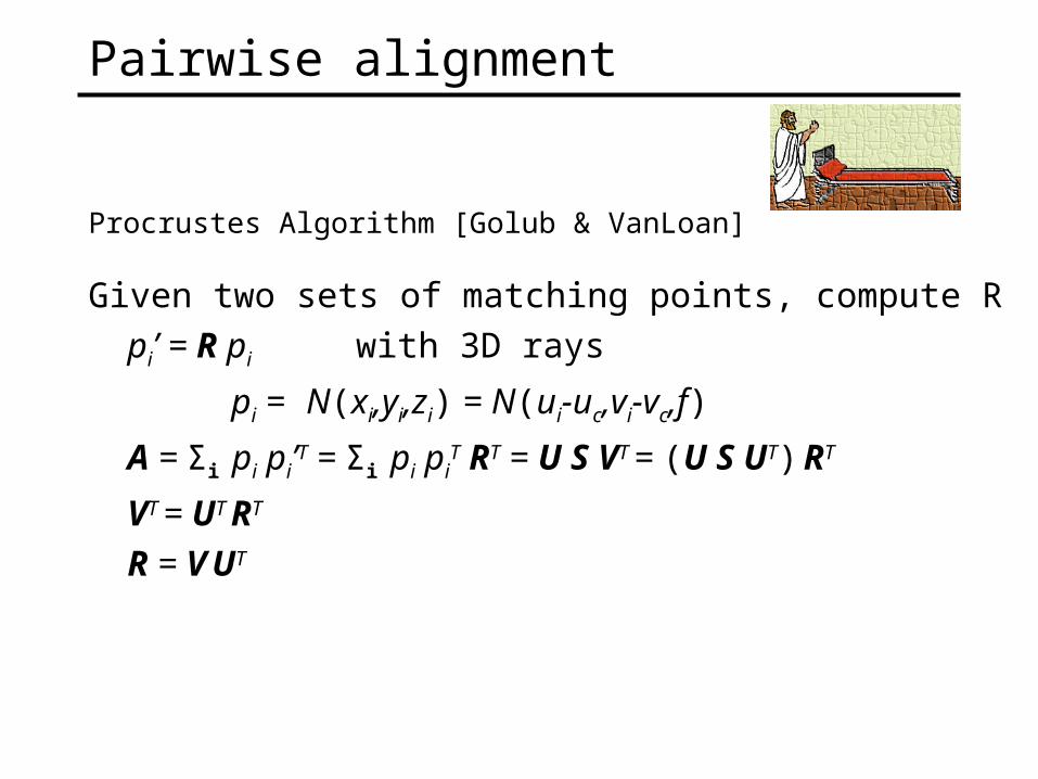
Pairwise alignment
Procrustes Algorithm [Golub & VanLoan]
Given two sets of matching points, compute R
pi’ = R pi with 3D rays
pi = N(xi,yi,zi) = N(ui-uc,vi-vc,f)
A = Σi pi pi’T = Σi pi piT RT = U S VT = (U S UT) RT
VT = UT RT
R = V UT
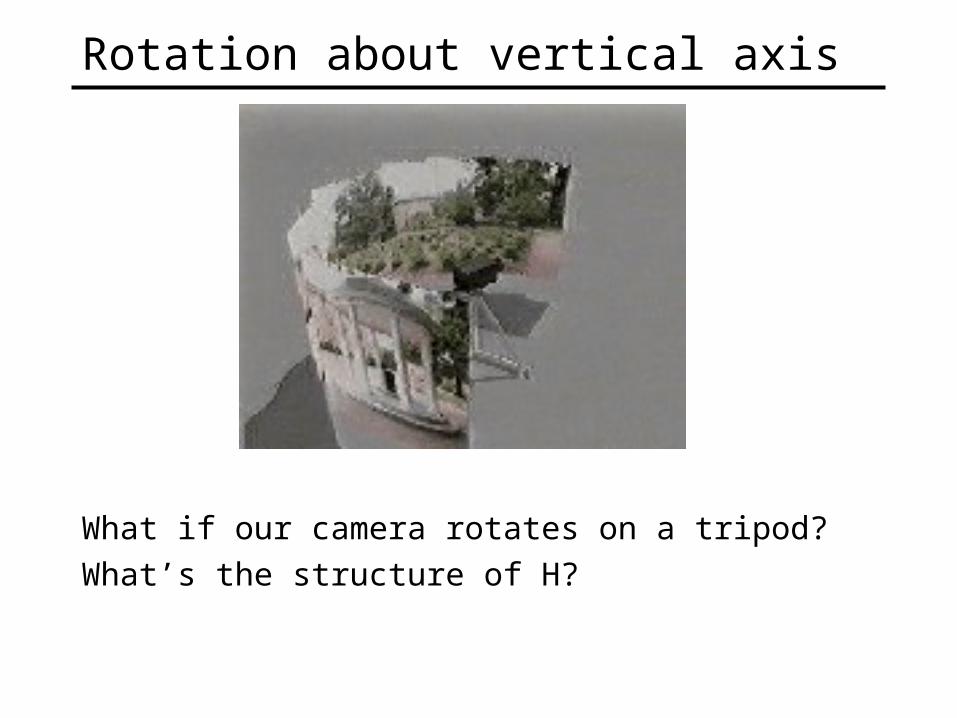
Rotation about vertical axis
What if our camera rotates on a tripod?
What’s the structure of H?

mosaic PP
Do we have to project onto a plane?
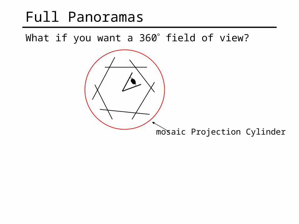
Full PanoramasWhat if you want a 360 field of view?
mosaic Projection Cylinder
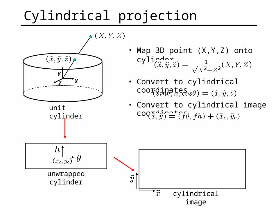
• Map 3D point (X,Y,Z) onto cylinder
Cylindrical projection
XY
Z
unit cylinder
unwrapped cylinder
• Convert to cylindrical coordinates
cylindrical image
• Convert to cylindrical image coordinates
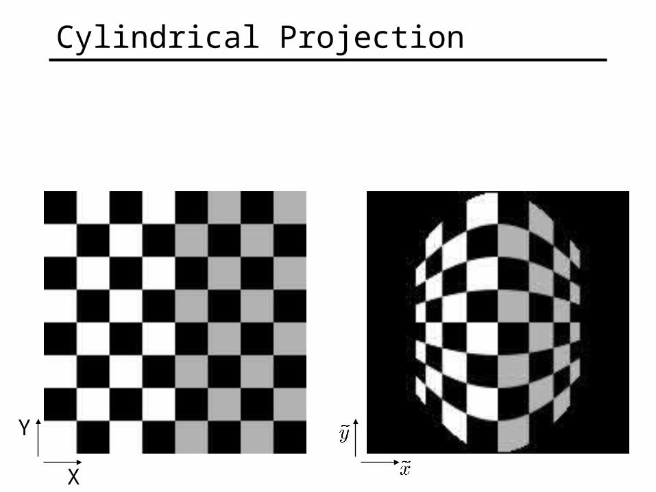
Cylindrical Projection
Y
X
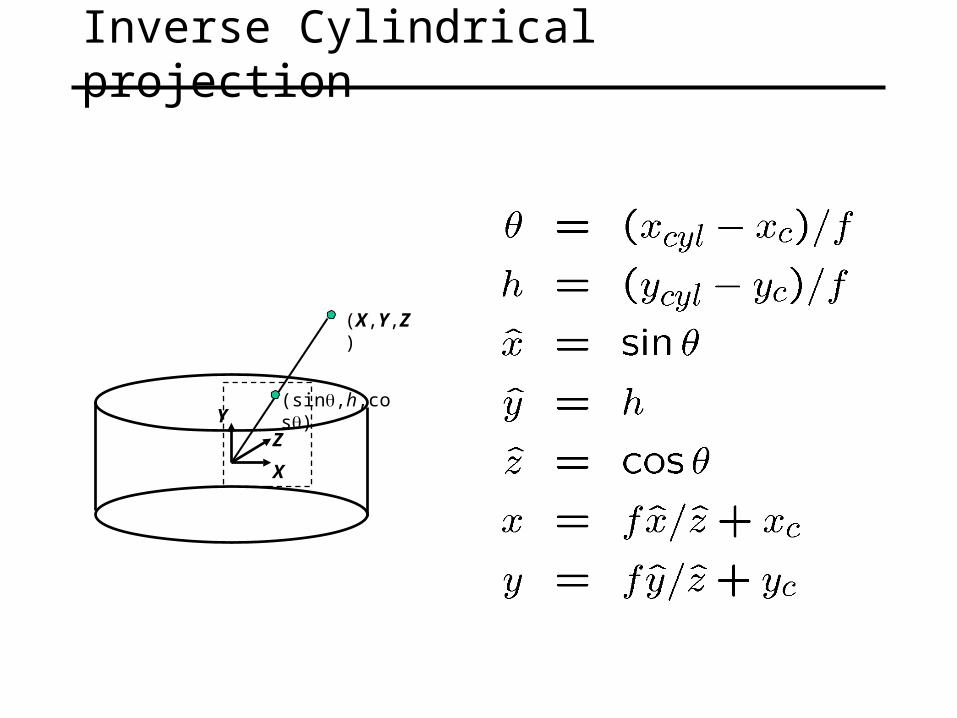
Inverse Cylindrical projection
X
YZ
(X,Y,Z)
(sin,h,cos)
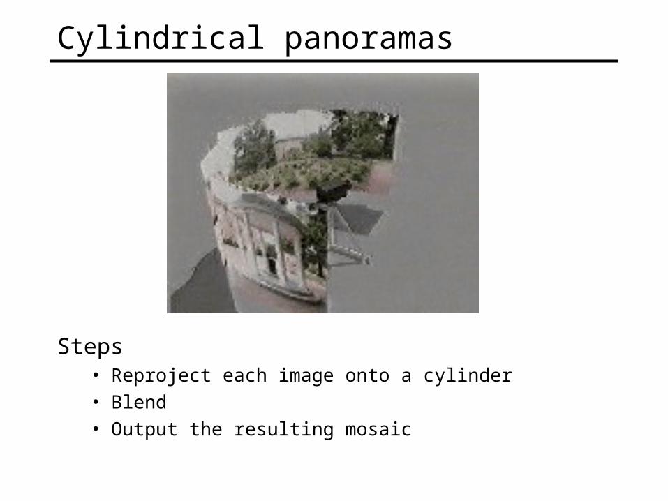
Cylindrical panoramas
Steps• Reproject each image onto a cylinder• Blend • Output the resulting mosaic
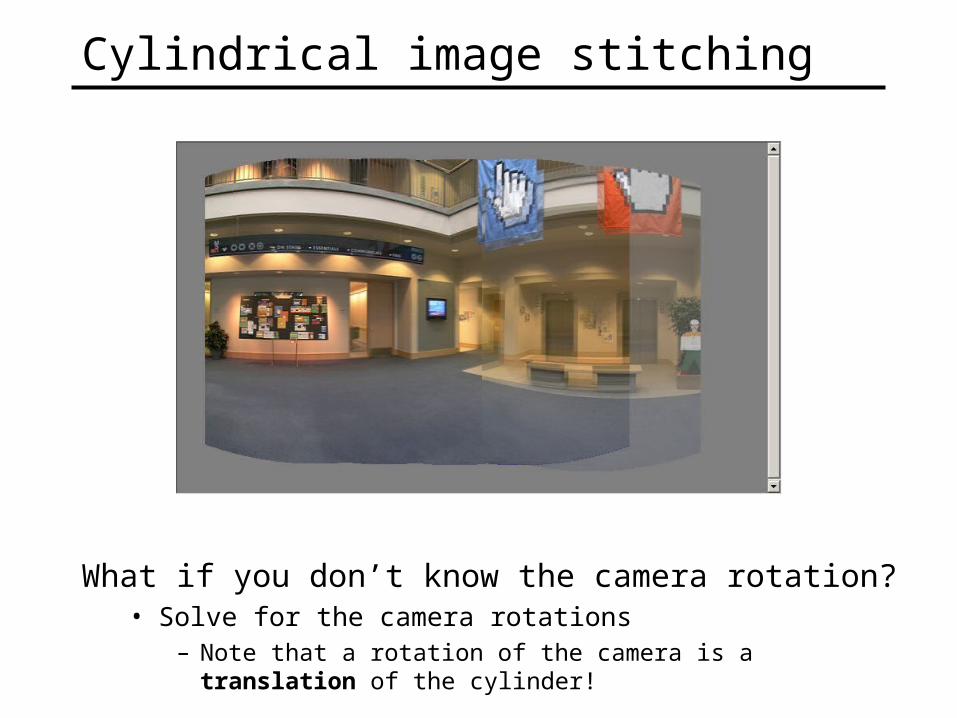
Cylindrical image stitching
What if you don’t know the camera rotation?• Solve for the camera rotations
– Note that a rotation of the camera is a translation of the cylinder!
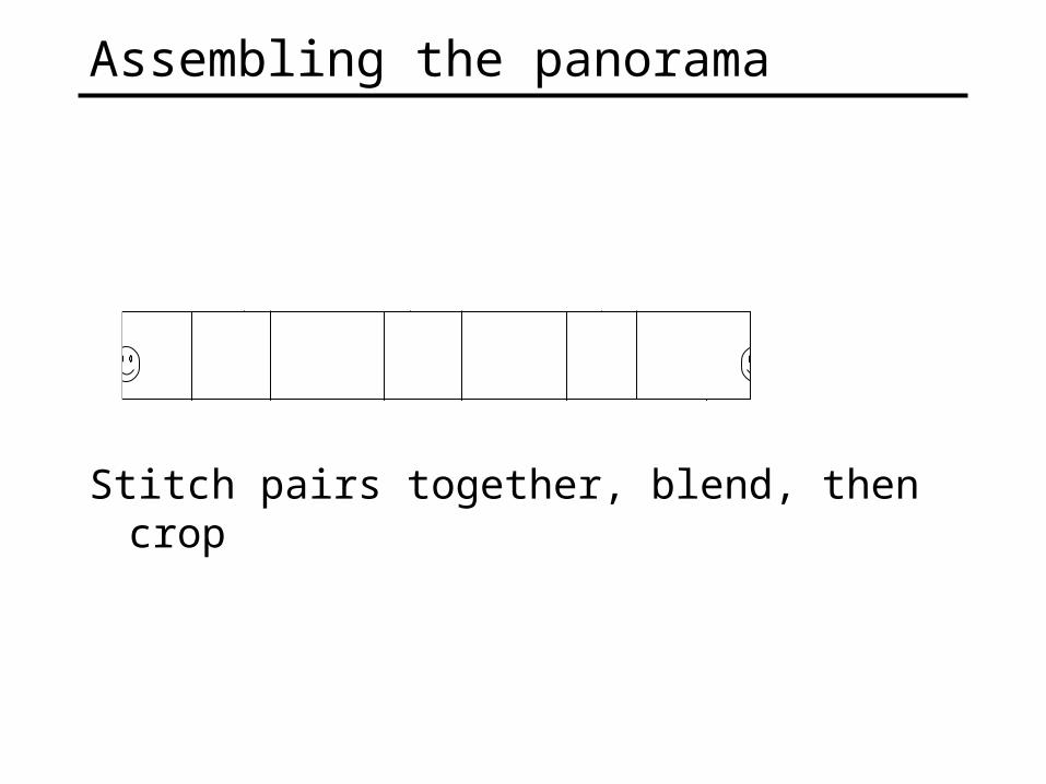
Assembling the panorama
Stitch pairs together, blend, then crop
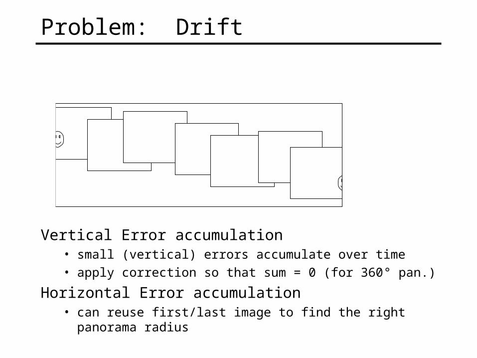
Problem: Drift
Vertical Error accumulation• small (vertical) errors accumulate over time• apply correction so that sum = 0 (for 360° pan.)
Horizontal Error accumulation• can reuse first/last image to find the right panorama radius
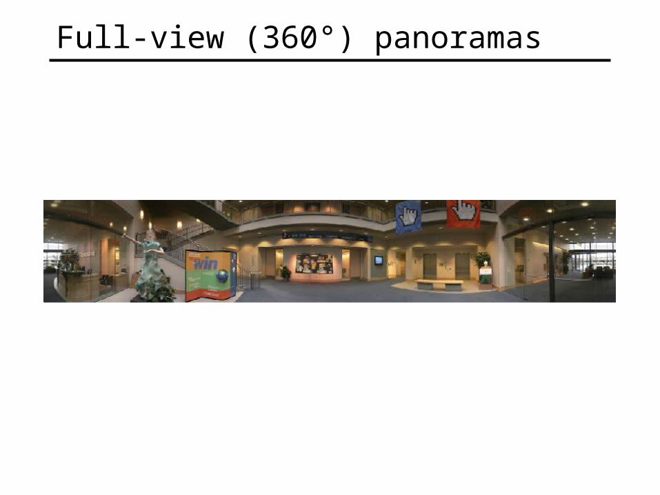
Full-view (360°) panoramas
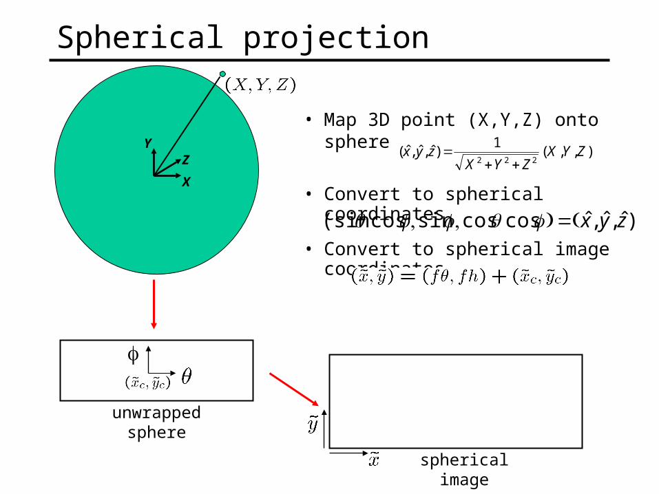
Spherical projection
unwrapped sphere
• Convert to spherical coordinates
spherical image
• Convert to spherical image coordinates
X
YZ
),,(1
)ˆ,ˆ,ˆ(222
ZYXZYX
zyx
• Map 3D point (X,Y,Z) onto sphere
)ˆ,ˆ,ˆcoscossincos(sin zyx
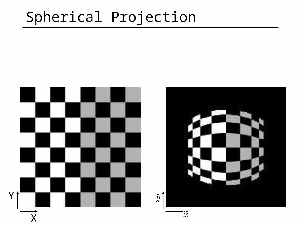
Spherical Projection
Y
X
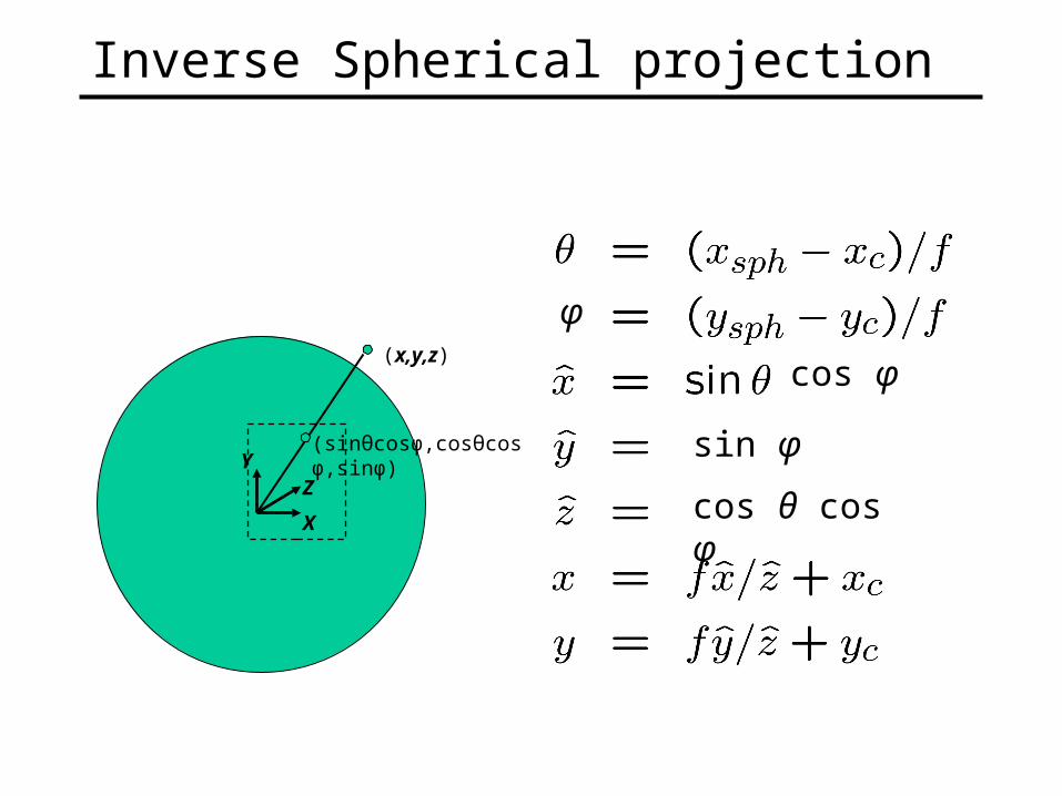
Inverse Spherical projection
X
YZ
(x,y,z)
(sinθcosφ,cosθcosφ,sinφ)
cos φ
φ
cos θ cos φ
sin φ
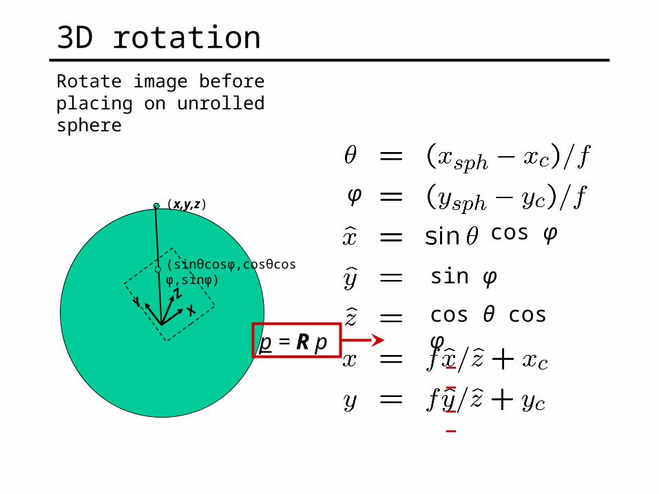
3D rotationRotate image before placing on unrolled sphere
XY
Z
(x,y,z)
(sinθcosφ,cosθcosφ,sinφ)
cos φ
φ
cos θ cos φ
sin φ
_ _
_ _
p = R p
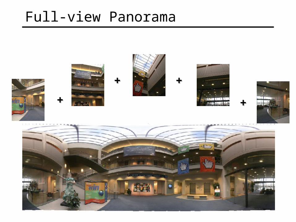
Full-view Panorama
++
++
++
++
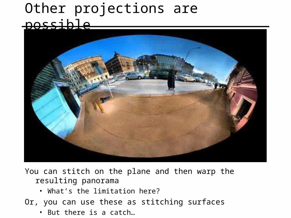
Other projections are possible
You can stitch on the plane and then warp the resulting panorama• What’s the limitation here?
Or, you can use these as stitching surfaces • But there is a catch…
f = 180 (pixels)
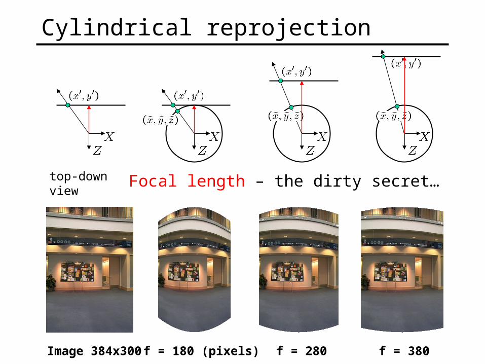
Cylindrical reprojection
f = 380f = 280Image 384x300
top-down view Focal length – the dirty secret…
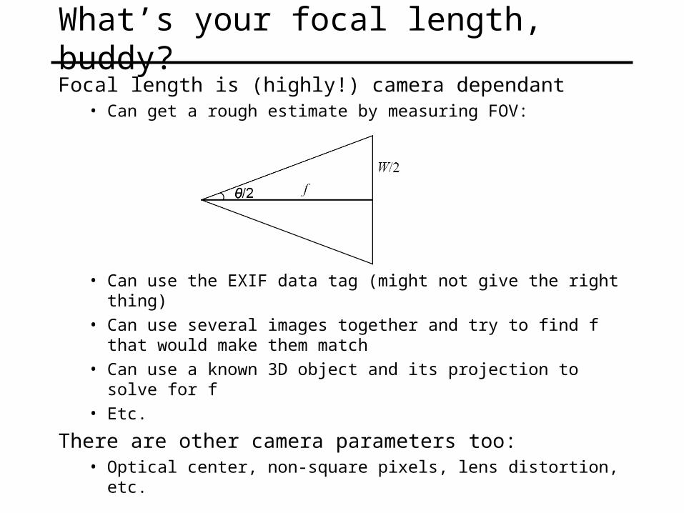
What’s your focal length, buddy?Focal length is (highly!) camera dependant
• Can get a rough estimate by measuring FOV:
• Can use the EXIF data tag (might not give the right thing)• Can use several images together and try to find f that would
make them match• Can use a known 3D object and its projection to solve for f• Etc.
There are other camera parameters too:• Optical center, non-square pixels, lens distortion, etc.
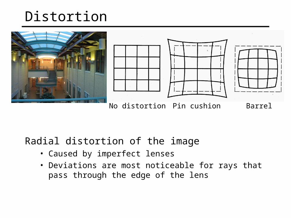
Distortion
Radial distortion of the image• Caused by imperfect lenses• Deviations are most noticeable for rays that pass through
the edge of the lens
No distortion Pin cushion Barrel
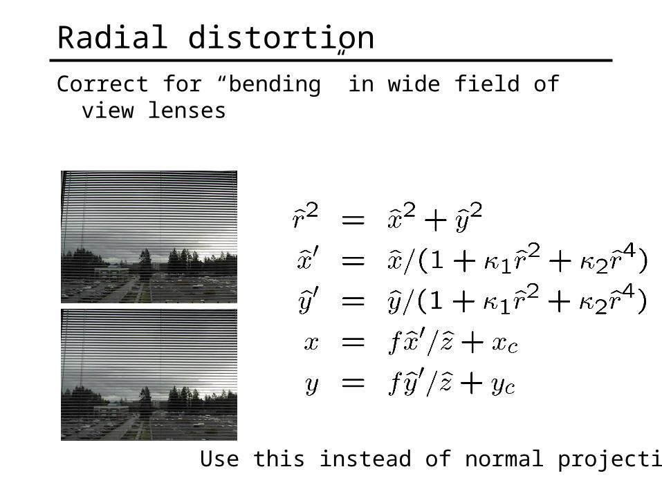
Radial distortionCorrect for “bending” in wide field of view lenses
Use this instead of normal projection
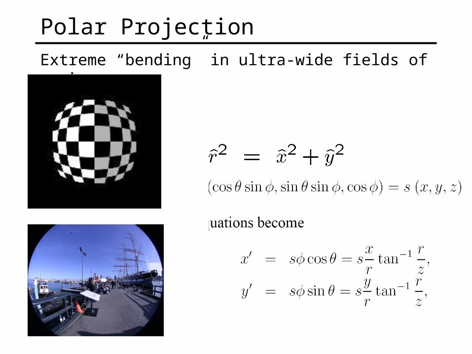
Polar ProjectionExtreme “bending” in ultra-wide fields of view
Camera calibrationDetermine camera parameters from known 3D points or
calibration object(s)
1. internal or intrinsic parameters such as focal length, optical center, aspect ratio:what kind of camera?
2. external or extrinsic (pose) parameters:where is the camera in the world coordinates?
• World coordinates make sense for multiple cameras / multiple images
How can we do this?
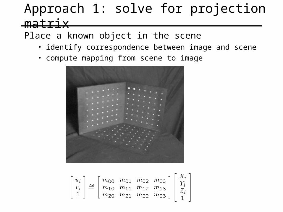
Approach 1: solve for projection matrix
Place a known object in the scene• identify correspondence between image and scene• compute mapping from scene to image
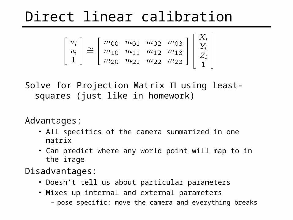
Direct linear calibration
Solve for Projection Matrix using least-squares (just like in homework)
Advantages:• All specifics of the camera summarized in one matrix• Can predict where any world point will map to in the image
Disadvantages:• Doesn’t tell us about particular parameters• Mixes up internal and external parameters
– pose specific: move the camera and everything breaks

Projection equation
• The projection matrix models the cumulative effect of all parameters
• Useful to decompose into a series of operations
ΠXx
1****
****
****
Z
Y
X
s
sy
sx
110100
0010
0001
100
'0
'0
31
1333
31
1333
x
xx
x
xxcy
cx
yfs
xfs
00
0 TIRΠ
projectionintrinsics rotation translation
identity matrix
Approach 2: solve for parametersA camera is described by several parameters
• Translation T of the optical center from the origin of world coords
• Rotation R of the image plane
• focal length f, principle point (x’c, y’c), pixel size (sx, sy)
• blue parameters are called “extrinsics,” red are “intrinsics”
• Solve using non-linear optimization
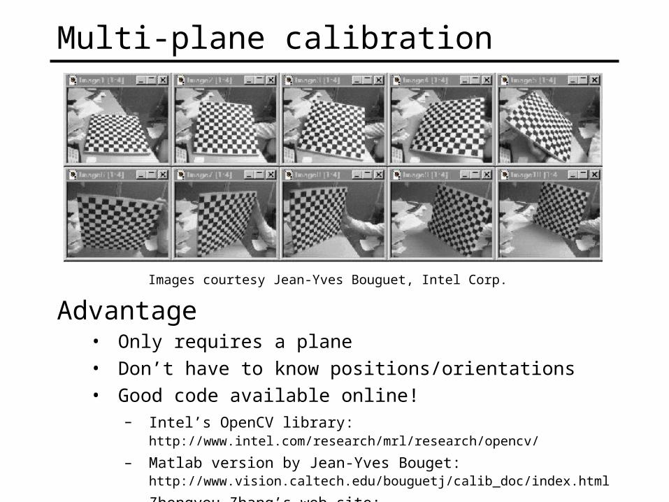
Multi-plane calibration
Images courtesy Jean-Yves Bouguet, Intel Corp.
Advantage• Only requires a plane• Don’t have to know positions/orientations• Good code available online!
– Intel’s OpenCV library: http://www.intel.com/research/mrl/research/opencv/
– Matlab version by Jean-Yves Bouget: http://www.vision.caltech.edu/bouguetj/calib_doc/index.html
– Zhengyou Zhang’s web site: http://research.microsoft.com/~zhang/Calib/


![[hal-00878580, v1] Towards Unsupervised Sudden Group ... · action class using a graphical model. Action Recognition is currently an active eld of research. Efros et al. (Efros et](https://static.fdocuments.net/doc/165x107/5f15048d826bff55f938589d/hal-00878580-v1-towards-unsupervised-sudden-group-action-class-using-a-graphical.jpg)


