MONTCLAIR/CEILING FAN MONTCLAIR/VENTILADOR DE TECHO...
24
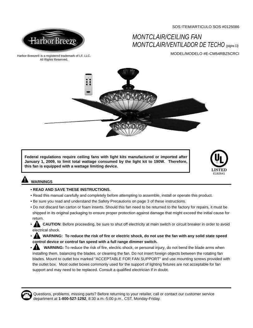
SOS ITEM/ARTICULO SOS #0125086 MONTCLAIR/CEILING FAN MONTCLAIR/VENTILADOR DE TECHO (página 13) MODEL/MODELO #E-CM54RBZ5CRCI WARNINGS • READ AND SAVE THESE INSTRUCTIONS. • Read this manual carefully and completely before attempting to assemble, install or operate this product. • Be sure you read and understand the Safety Precautions on page 3 of these instructions. • Do not discard fan carton or foam inserts. Should this fan need to be returned to the factory for repairs, it must be shipped in its original packaging to ensure proper protection against damage that might exceed the initial cause for return. • CAUTION: Before proceeding, be sure to shut off electricity at main switch or circuit breaker in order to avoid electrical shock. • WARNING: To reduce the risk of fire or electric shock, do not use the fan with any solid state speed control device or control fan speed with a full range dimmer switch. • WARNING: To reduce the risk of fire, electric shock, or personal injury, do not bend the blade arms when installing them, balancing the blades, or cleaning the fan. Do not insert foreign objects between the rotating fan blades. Mount to outlet box marked "ACCEPTABLE FOR FAN SUPPORT" and use mounting screws provided with the outlet box. Most outlet boxes commonly used for the support of lighting fixtures are not acceptable for fan support and may need to be replaced. Consult a qualified electrician if in doubt. Questions, problems, missing parts? Before returning to your retailer, call or contact our customer service department at 1-800-527-1292, 8:30 a.m.-5:00 p.m., CST, Monday-Friday. Harbor Breeze® is a registered trademark of LF, LLC. All Rights Reserved. Federal regulations require ceiling fans with light kits manufactured or imported after January 1, 2009, to limit total wattage consumed by the light kit to 190W. Therefore, this fan is equipped with a wattage limiting device. E192641
Transcript of MONTCLAIR/CEILING FAN MONTCLAIR/VENTILADOR DE TECHO...
SOS ITEM/ARTICULO SOS #0125086
MONTCLAIR/CEILING FANMONTCLAIR/VENTILADOR DE TECHO (página 13)
MODEL/MODELO #E-CM54RBZ5CRCI
WARNINGS • READ AND SAVE THESE INSTRUCTIONS.• Read this manual carefully and completely before attempting to assemble, install or operate this product.• Be sure you read and understand the Safety Precautions on page 3 of these instructions.• Do not discard fan carton or foam inserts. Should this fan need to be returned to the factory for repairs, it must beshipped in its original packaging to ensure proper protection against damage that might exceed the initial cause for return.
• CAUTION: Before proceeding, be sure to shut off electricity at main switch or circuit breaker in order to avoidelectrical shock.
• WARNING: To reduce the risk of fire or electric shock, do not use the fan with any solid state speedcontrol device or control fan speed with a full range dimmer switch.
• WARNING: To reduce the risk of fire, electric shock, or personal injury, do not bend the blade arms wheninstalling them, balancing the blades, or cleaning the fan. Do not insert foreign objects between the rotating fan blades. Mount to outlet box marked "ACCEPTABLE FOR FAN SUPPORT" and use mounting screws provided with the outlet box. Most outlet boxes commonly used for the support of lighting fixtures are not acceptable for fan support and may need to be replaced. Consult a qualified electrician if in doubt.
Questions, problems, missing parts? Before returning to your retailer, call or contact our customer service department at 1-800-527-1292, 8:30 a.m.-5:00 p.m., CST, Monday-Friday.
Harbor Breeze® is a registered trademark of LF, LLC. All Rights Reserved.
Federal regulations require ceiling fans with light kits manufactured or imported after January 1, 2009, to limit total wattage consumed by the light kit to 190W. Therefore, this fan is equipped with a wattage limiting device.
E192641

2
TABLE OF CONTENTS
Safety Information ........................…………………………………………………………………….……...……..….3
Package Contents .............................…………………………………………………………………………...……..4
Preparation .........................................….…………………..……………………….…………….………………..5
Initial Installation .........................................…………………………………………………...........…………...…..5
Fan Mounting ..........................………......................………………………………….………………………...….6
Wiring for Remote Control and Fan .............................................................………………………………......6 - 7
Final Installation ............………………….…………….……………………….…………….……...............…….7 - 8
Automated Learning Process/Activating Code ....................................................……………………………………..…..9
Remote Control and Fan Operation .......................................................................................................9 - 10
Lighted Housing Bulb Replacement ......................................................................................................................10
Care and Maintenance ........................………………………………………………………..…………......…..10
Troubleshooting ............................................…………………………………………………..………....…….....11
Warranty ........................…………………………………….…………………………………………..………....... 12

SAFETY INFORMATION READ AND SAVE THESE INSTRUCTIONSPlease read and understand this entire manual before attempting to assemble, install or operate the product. If you have any questions regarding the product, please call customer service at 1-800-527-1292, 8:30 a.m.-5:00 p.m., CST, Monday-Friday. 1. Before you begin installing the fan, disconnect the power by removing fuses or turning off circuit breakers. 2. CAUTION: Read all instructions and safety information before installing your new fan. Review the
accompanying assembly diagrams. 3. CAUTION: To avoid personal injury, the use of gloves may be necessary while handling fan parts with
sharp edges. 4. Make sure that all electrical connections comply with local codes, ordinances, the National Electrical Code and
ANSI/NFPA 70-1999. Hire a qualified electrician or consult a do-it-yourself wiring handbook, available at Lowe's, if you are unfamiliar with installing electrical wiring.
5. Make sure the installation site you choose allows a minimum clearance of 7 feet from the blades to the floor andat least 30 in. from the end of the blades to any obstruction.
6. WARNING: To reduce the risk of fire, electrical shock, or personal injury, mount fan to outlet box marked"ACCEPTABLE FOR FAN SUPPORT" and use mounting screws provided with the outlet box. Most outlet boxes commonly used for the support of lighting fixtures are not acceptable for fan support and may need to be replaced. Consult a qualified electrician if in doubt. Secure the box directly to the building structure. The outlet box and its support must be able to support the moving weight of the fan (at least 35 lbs.). Do NOT use a plastic outlet box.
7. After you install the fan, make sure that all connections are secure to prevent the fan from falling. 8. WARNING: To reduce the risk of fire, electrical shock, or personal injury, wire connectors provided with
this fan are designed to accept only one 12 gauge house wire and two lead wires from the fan. If your house wire is larger than 12 gauge or there is more than one house wire to connect to the two fan lead wires, consult an electrician for the proper size wire connectors to use.
9. WARNING: To reduce the risk of fire or electric shock, do not use the fan with any solid statespeed control device or control fan speed with a full range dimmer switch.
10. WARNING: To reduce the risk of fire, electric shock, or personal injury, do not bend the blade arms wheninstalling them, balancing the blades, or cleaning the fan. Do not insert objects between the rotating fan blades.
11. WARNING: To reduce the risk of personal injury, use only parts provided with this fan. The use of partsOTHER than those provided with this fan will void the warranty.
12. The net weight of this fan including the light kit is: 29.21 lbs. (13.25 kg).
3
4
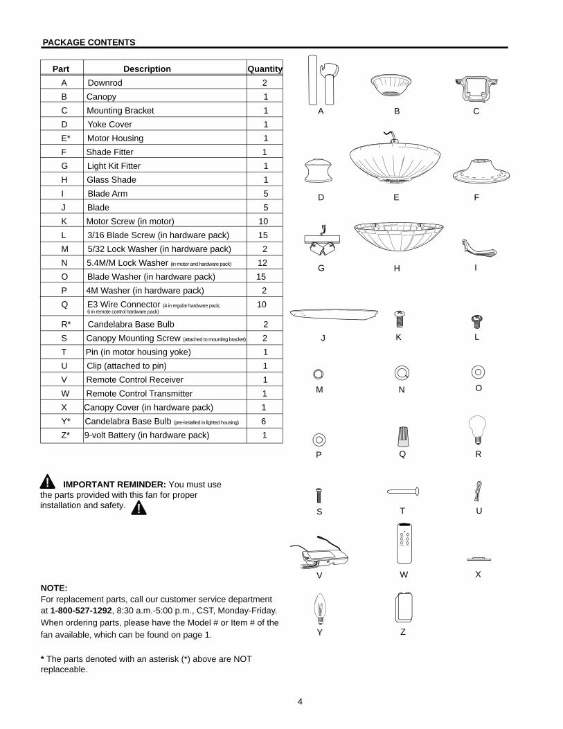
PACKAGE CONTENTS Part Description Quantity
A Downrod 2B Canopy 1C Mounting Bracket 1D Yoke Cover 1E* Motor Housing 1F Shade Fitter 1G Light Kit Fitter 1H Glass Shade 1I Blade Arm 5J Blade 5K Motor Screw (in motor) 10L 3/16 Blade Screw (in hardware pack) 15M 5/32 Lock Washer (in hardware pack) 2N 5.4M/M Lock Washer (in motor and hardware pack) 12O Blade Washer (in hardware pack) 15P 4M Washer (in hardware pack) 2Q E3 Wire Connector (4 in regular hardware pack; 10 6 in remote control hardware pack)
R* Candelabra Base Bulb 2S Canopy Mounting Screw (attached to mounting bracket) 2T Pin (in motor housing yoke) 1U Clip (attached to pin) 1V Remote Control Receiver 1W Remote Control Transmitter 1X Canopy Cover (in hardware pack) 1Y* Candelabra Base Bulb (pre-installed in lighted housing) 6Z* 9-volt Battery (in hardware pack) 1
A B C
D E F
G H I
J K L
M N O
P Q R
S T U
V W X
Y
NOTE:For replacement parts, call our customer service departmentat 1-800-527-1292, 8:30 a.m.-5:00 p.m., CST, Monday-Friday.When ordering parts, please have the Model # or Item # of thefan available, which can be found on page 1.
* The parts denoted with an asterisk (*) above are NOT replaceable.
IMPORTANT REMINDER: You must use the parts provided with this fan for proper installation and safety.
Z
5
INITIAL INSTALLATION
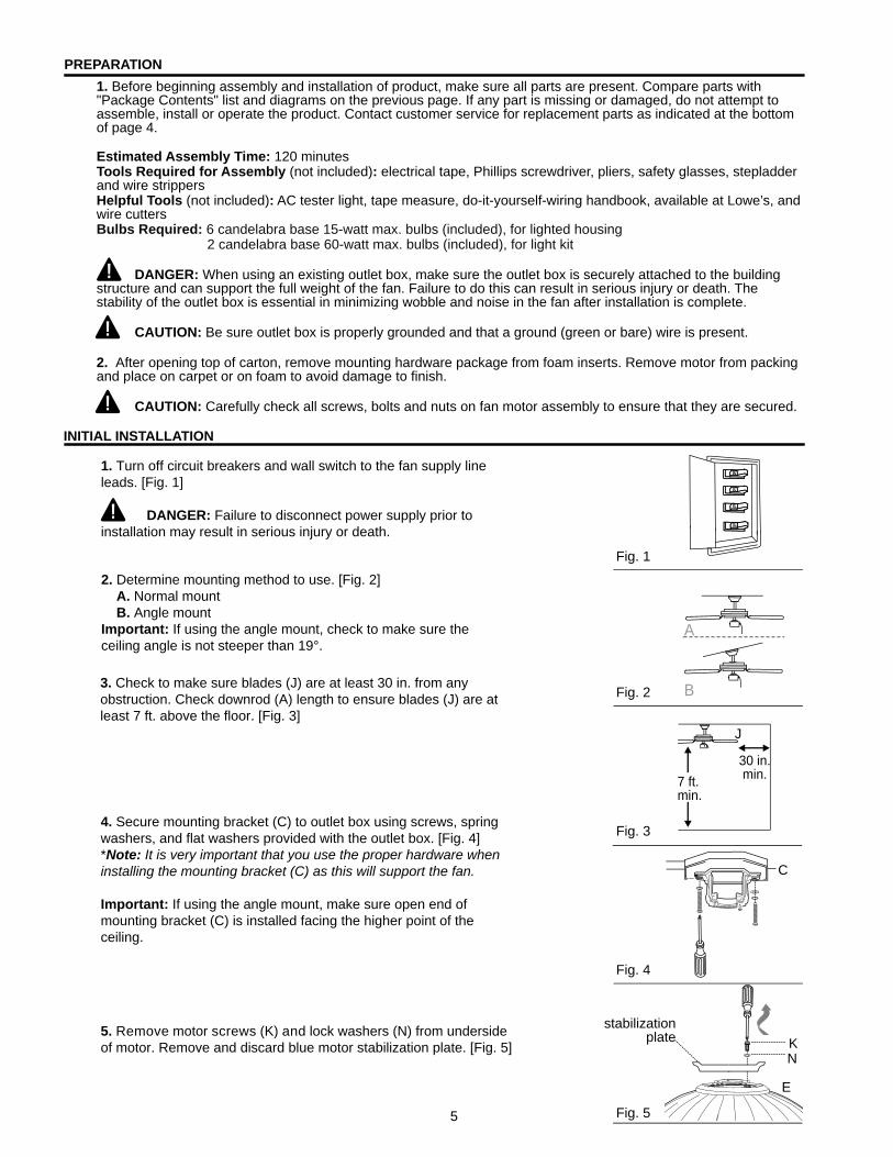
1. Turn off circuit breakers and wall switch to the fan supply line leads. [Fig. 1] DANGER: Failure to disconnect power supply prior to installation may result in serious injury or death.
3. Check to make sure blades (J) are at least 30 in. from any obstruction. Check downrod (A) length to ensure blades (J) are at least 7 ft. above the floor. [Fig. 3]
5. Remove motor screws (K) and lock washers (N) from underside of motor. Remove and discard blue motor stabilization plate. [Fig. 5]
1. Before beginning assembly and installation of product, make sure all parts are present. Compare parts with "Package Contents" list and diagrams on the previous page. If any part is missing or damaged, do not attempt to assemble, install or operate the product. Contact customer service for replacement parts as indicated at the bottom of page 4. Estimated Assembly Time: 120 minutesTools Required for Assembly (not included): electrical tape, Phillips screwdriver, pliers, safety glasses, stepladder and wire strippersHelpful Tools (not included): AC tester light, tape measure, do-it-yourself-wiring handbook, available at Lowe’s, and wire cuttersBulbs Required: 6 candelabra base 15-watt max. bulbs (included), for lighted housing 2 candelabra base 60-watt max. bulbs (included), for light kit DANGER: When using an existing outlet box, make sure the outlet box is securely attached to the building structure and can support the full weight of the fan. Failure to do this can result in serious injury or death. The stability of the outlet box is essential in minimizing wobble and noise in the fan after installation is complete. CAUTION: Be sure outlet box is properly grounded and that a ground (green or bare) wire is present. 2. After opening top of carton, remove mounting hardware package from foam inserts. Remove motor from packing and place on carpet or on foam to avoid damage to finish. CAUTION: Carefully check all screws, bolts and nuts on fan motor assembly to ensure that they are secured.
Fig. 1
Fig. 2
Fig. 3
Fig. 4
Fig. 5
J
B
A
7 ft.min.
30 in.min.
2. Determine mounting method to use. [Fig. 2] A. Normal mount B. Angle mountImportant: If using the angle mount, check to make sure the ceiling angle is not steeper than 19°.
4. Secure mounting bracket (C) to outlet box using screws, spring washers, and flat washers provided with the outlet box. [Fig. 4]*Note: It is very important that you use the proper hardware when installing the mounting bracket (C) as this will support the fan.
Important: If using the angle mount, make sure open end of mounting bracket (C) is installed facing the higher point of the ceiling.
C
PREPARATION
NK
stabilization plate
E

WIRING FOR REMOTE CONTROL AND FAN (continued on next page)
6
3. Slip downrod (A) into housing yoke, align holes and re-install pin (T) and clip (U). Tighten downrod (A) set screws and then tighten nuts. Slide yoke cover (D) down until it rests on top of motor housing (E). [Fig. 3]
FAN MOUNTING
4. Install ball end of downrod (A) into mounting bracket (C) opening. Align slot in ball with tab in mounting bracket (C). [Fig. 4]
DANGER: Failure to align slot in ball with tab may result in serious injury or death.
1. Remove pin (T) and clip (U) from motor housing yoke at top of motor housing (E) and partially loosen set screws. [Fig. 1]
*Helpful Hint: Downrod style mounting is best suited for ceilings 8 ft. high or higher. For taller ceilings you may want to use a longer downrod (not included) than the ones supplied. Angle style mounting is best suited for angled or vaulted ceilings. Longer downrods are sometimes necessary to ensure proper blade clearance.
2. Choose downrod (A) length you wish to use.* If you chose to use the 12 in. downrod (A), remove hanging ball from the 6 in. downrod (A) and attach to the 12 in. downrod (A). Insert downrod (A) through canopy (B), canopy cover (X), and yoke cover (D). [Note: Canopy cover (X) must be turned with the shiny side toward the motor housing (E).] Thread wires from motor housing (E) through downrod (A). [Fig. 2]
Note: Black wire is hot power for fan. Orange wire is hot power for lighted housing. Blue wire is hot power for light kit. White wire is common for fan and light kit. Green wire is ground.
Fig. 2
Fig. 4
D
D
E
T
B
U
A
A
Fig. 3
WARNING: If house wires are different colors than referred to in the next steps, stop immediately. A professional electrician is recommended to determine wiring.
CAUTION: Be sure wiring box is properly grounded and that a ground wire (green or bare) is present.
Note: Please refer to installation and operating instructions for remote control.
X
WARNING: To reduce the risk of fire, electrical shock, or personal injury, wire connectors provided with this fan are designed to accept only one 12 gauge house wire and two lead wires from the fan. If your house wire is larger than 12 gauge or there is more than one house wire to connect to the two fan lead wires, consult an electrician for the proper size wire connectors to use.
SetScrew
Fig. 1E
TU
Hanging Ball Slot
Tab
C
Ball
B
A

7
2. Tape wire connectors (Q) and wires together with electrical tape. [Fig. 2]
Warning: Make sure no bare wire or wire strands are visible after making connections. Place green and white connections on opposite side of box from the black, orange and blue (if applicable) connections.
1. Make the necessary wiring connections for remote operation according to Fig. 1. For each wire connection, use one of the wire connectors (Q) provided, making sure to screw wire connector (Q) on in a clockwise direction. [Make sure to connect all GROUND (GREEN) wires together from fan (on downrod and mounting bracket) to BARE/GREEN wire from ceiling.]WIRING TIP: Wiring your fan's remote control requires extreme patience. Take mandatory breaks while wiring to allow your arms to rest.
Antenna
V A
C
Fig. 3
Fig. 1
3. Gently slide remote control receiver (V), flat side up, into mounting bracket (C). Turn spliced/taped wires upward and gently push wires and wire connectors (Q) into outlet box. Let antenna from receiver (V) hang to the side. [Fig. 3]
Note: The remote control included with this fan meets the following requirements: a. Not for use with solid state fans. b. Electrical rating: 120V / 60 Hz; motor amps:1.0 MAX.; light watts: 300 (incandescent only).
Fig. 2
Q
black
black
black
from fan
white
white
blue
blue
black supply wire
ground (greenor bare)
white supply wire
whiteAC IN N
AC IN L
V
black
white
ground (green or bare)
antenna
from receiverfrom receiver
from ceiling
orange
oran
ge
WIRING FOR REMOTE CONTROL AND FAN (continued from previous page)
FINAL INSTALLATION (continued on next page)
Fig. 1
A
X
B
S
1. Locate two canopy mounting screws (S) on underside of mounting bracket (C) and remove screw (S) closest to the open end of of the hanging bracket (C). Partially loosen the other screw (S). Lift canopy (B) to mounting bracket (C). Place rounded part of slotted hole in canopy (B) over loosened screw (S) in hanging bracket (C) and push up. Twist canopy (B) to lock. Re-insert screw (S) that was removed, and then tighten both screws (S) securely. Slide canopy cover (X) up to canopy (B), aligning rounded part of slotted holes in canopy cover (X) with screwheads in bottom of canopy (B). Turn canopy cover (X) to the right (clockwise) until it stops. [Fig. 1]

8
FINAL INSTALLATION (continued from previous page)
6. Partially loosen two screws on the underside of the shade fitter (F) and remove the other screw. Connect WHITE wire from light kit fitter (G) to WHITE wire from motor housing (E). Connect BLACK wire from light kit fitter (G) to BLACK wire from motor housing (E). Make sure that molex connections snap together securely.
Carefully arrange wiring within light kit fitter (G). Align slotted holes in light kit fitter (G) with loosened screws in shade fitter (F). Twist light kit fitter (G) to lock. Re-insert screw that was removed and tighten all screws securely. [Fig. 6]
5. Remove one screw on fitter plate (on underside of motor) and loosen the other two screws. Align slotted holes in shade fitter (F) with loosened screws in fitter plate. Twist shade fitter (F) to lock and re-install screw that was previously removed. Tighten all screws securely. [Fig. 5]
4. Place remaining lock washers (N) and insert motor screws (K). Repeat with remaining blade arms (I). Tighten all motor screws (K) securely. [Fig. 4]
3. Locate motor screws (K) and lock washers (N) that were previously removed on page 5. (Additional motor screws (K) and lock washers (N) are in hardware pack.) Insert only one motor screw (K), along with lock washer (N), through blade arm (I) to attach blade arm (I) to motor and partially tighten the motor screw (K). Repeat with remaining blade arms (I). [Fig. 3]
Fig. 2
2. Position blade arm (I) under blade (J) and secure blade arm (I) with screws (L) and washers (O). Do not tighten screws (L) until each screw (L) has been started. Then, tighten each screw (L) starting with the center screw (L). Repeat for the remaining blades (J). [Fig. 2]
E
F
fitter plate
Fig. 5
Fig. 6
E
F
G
Fig. 4
JI
E
Fig. 3
E
I/JK
N
J
I
LO
Fig. 8
E
F
H
8. Remove one screw from inside glass shade (H) and partially loosen the other three screws. Align the three loosened screws in glass shade (H) with slotted holes in shade fitter (F). Twist glass shade to lock. Re-insert screw that was previously removed and secure all four screws with a Phillips screwdriver. [Fig. 8]Tip:Use a short Phillips screwdriver for easier access to screws in shade fitter (F).
7. Install two candelabra base 60 watt max. bulbs (R) included. [Fig. 7]
Important: When replacing bulbs, allow bulb(s) and glass shade (H) to cool before touching them. Fig. 7
RF
E

9
REMOTE CONTROL AND FAN OPERATION (continued on next page)
W
Fig. 1
W
Code Switches
Pen
BatteryCover
1. Operation buttons on the panel of the remote control transmitter (W) [Fig. 1]:
HI button for fan HIGH speedMED button for fan MEDIUM speedLOW button for fan LOW speedFAN/OFF button for turning fan OFFTOP LIGHT button for light BRIGHTNESS and OFF, upper lightBTM LIGHT button for light BRIGHTNESS and OFF, lower light
The light function is controlled by pressing the TOP LIGHT and/or BTM LIGHT button. Hold either button down to increase or decrease light. Tap either button quickly to turn light off or on. If you press either button in excess of 0.7 seconds it becomes a dimmer. The light varies cyclically in 0.8 seconds. The light buttons have an auto resume function which keeps the light at the same brightness as the last time it was turned off.
IMPORTANT: Turn fan off at wall switch and let blades (J) come to a complete stop before manually activating the reverse switch.
Z1
AUTOMATED LEARNING PROCESS/ACTIVATING CODE
CAUTION: The remote control transmitter (W) can be programmed to multiple receivers or fans. If this is not desired, turn wall switch off to any other programmable receiver or fan.
1. Remove battery cover from back side of remote control transmitter (W).
2. Set the code on the remote control transmitter (W) by sliding code switches 1 through 4 to your choice of up or down position. (Factory setting is all up. Do not use this position.) Use a small screwdriver or ballpoint pen to slide firmly up or down. [Fig. 1]
3. Locate dimmer switch to the right of the code switches labeled with a “D” and an “X”. [Fig. 1] Set dimmer switch to the “ON” (D) position only if using incandescent bulbs. Set dimmer switch to “OFF” (X) position if using compact fluorescent bulbs. NOTE: Most compact fluorescent bulbs are not compatible for use with dimmer controls.
4. Install the 9-volt battery (Z) provided.
5. Restore electrical power. Within 30 seconds of restoring electrical power, press the “FAN/OFF” button on the remote control transmitter (W) for 5 seconds or until lower light blinks twice. Test the light and fan functions to confirm the learning process is complete. [Fig. 2]
6. Replace battery cover on remote control transmitter (W). [Fig. 1]
IMPORTANT: To prevent damage to remote control transmitter (W), remove the battery (Z) if not used for long periods. Store the remote control transmitter (W) away from excess heat or humidity.
This remote control transmitter (W) is equipped with 16 code combinations to prevent possible interference from or to other remote units such as garage door openers, car alarms or security systems. If you find that your fan and light kit go on and off without using your remote control, simply change the combination code in your remote control. If you do change the combination code turn power off and repeat Steps 5 and 6 above.
DimmerSwitch
Fig. 1
Fig. 2
W

10
Fig. 2
Fig. 2A Fig. 2B
2. Use the fan reverse switch, located on top of the motor housing (E), to optimize your fan for seasonal performance. [Fig. 2] A ceiling fan will allow you to raise your thermostat setting in summer and lower your thermostat setting in winter without feeling a difference in your comfort.
Note: Wait for fan to stop before moving the reverse switch.
2A. In warmer weather, setting the reverse switch to theLEFT will result in downward airflow creating a wind chilleffect. [Fig. 2A]
2B. In cooler weather, setting the reverse switch to theRIGHT will result in upward airflow that can help movestagnant, hot air off the ceiling area. [Fig. 2B]
IMPORTANT: Reverse switch must be set either completely to the RIGHT or completely to the LEFT for fan to function. If the reverse switch is set in the middle position [Fig. 2C], fan will not operate.
Fig. 2C
CARE AND MAINTENANCE
At least twice each year, lower canopy (B) to check downrod (A) assembly, and then tighten all screws on the fan. Clean motor housing (E) with only a soft brush or lint-free cloth to avoid scratching the finish. Clean blades (J) with a lint-free cloth. You may occasionally apply a light coat of furniture polish to wood blades for added protection.Important: Shut off main power supply before beginning any maintenance. Do not use water or a damp cloth to clean the ceiling fan.
LIGHTED HOUSING BULB REPLACEMENT
Important: Allow motor housing (E) and bulbs (Y) to cool down before touching them.
When it becomes time to replace bulbs (Y) in the lighted motor housing (E), locate six access covers on the top of the motor housing (E). Determine which access cover contains the burnt-out bulb (Y). Remove the access cover by removing the two screws at the edges of the access cover--this will allow access to the burnt-out bulb (Y). Replace burnt-out bulb (Y) with one candelabra base 15 watt max. bulb. Repeat for each burnt-out bulb (Y). After replacing bulb(s), re-install screws that were previously removed Tighten all screws securely.
AccessCovers
Y
E,(topview)
E(top view)
REMOTE CONTROL AND FAN OPERATION (continued from previous page)
reverseswitch
11
TROUBLESHOOTING
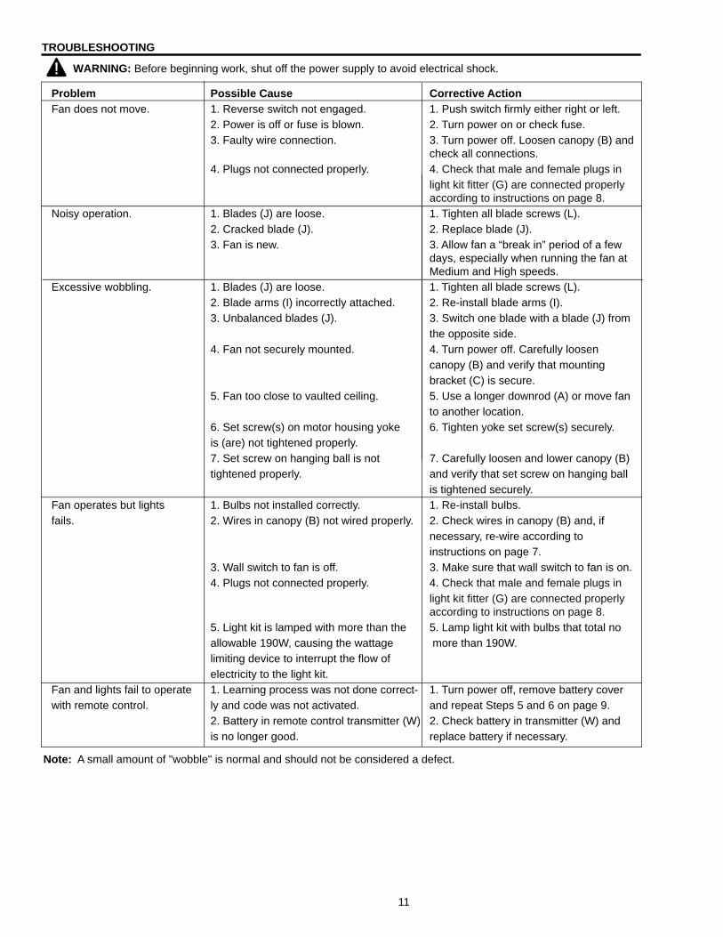
Problem Possible Cause Corrective ActionFan does not move. 1. Reverse switch not engaged. 1. Push switch firmly either right or left. 2. Power is off or fuse is blown. 2. Turn power on or check fuse. 3. Faulty wire connection. 3. Turn power off. Loosen canopy (B) and check all connections. 4. Plugs not connected properly. 4. Check that male and female plugs in light kit fitter (G) are connected properly according to instructions on page 8.Noisy operation. 1. Blades (J) are loose. 1. Tighten all blade screws (L). 2. Cracked blade (J). 2. Replace blade (J). 3. Fan is new. 3. Allow fan a “break in” period of a few days, especially when running the fan at Medium and High speeds.Excessive wobbling. 1. Blades (J) are loose. 1. Tighten all blade screws (L). 2. Blade arms (I) incorrectly attached. 2. Re-install blade arms (I). 3. Unbalanced blades (J). 3. Switch one blade with a blade (J) from the opposite side. 4. Fan not securely mounted. 4. Turn power off. Carefully loosen canopy (B) and verify that mounting bracket (C) is secure. 5. Fan too close to vaulted ceiling. 5. Use a longer downrod (A) or move fan to another location. 6. Set screw(s) on motor housing yoke 6. Tighten yoke set screw(s) securely. is (are) not tightened properly. 7. Set screw on hanging ball is not 7. Carefully loosen and lower canopy (B) tightened properly. and verify that set screw on hanging ball is tightened securely.Fan operates but lights 1. Bulbs not installed correctly. 1. Re-install bulbs.fails. 2. Wires in canopy (B) not wired properly. 2. Check wires in canopy (B) and, if necessary, re-wire according to instructions on page 7. 3. Wall switch to fan is off. 3. Make sure that wall switch to fan is on. 4. Plugs not connected properly. 4. Check that male and female plugs in light kit fitter (G) are connected properly according to instructions on page 8. 5. Light kit is lamped with more than the 5. Lamp light kit with bulbs that total no allowable 190W, causing the wattage more than 190W. limiting device to interrupt the flow of electricity to the light kit.Fan and lights fail to operate 1. Learning process was not done correct- 1. Turn power off, remove battery coverwith remote control. ly and code was not activated. and repeat Steps 5 and 6 on page 9. 2. Battery in remote control transmitter (W) 2. Check battery in transmitter (W) and is no longer good. replace battery if necessary.
Note: A small amount of "wobble" is normal and should not be considered a defect.
WARNING: Before beginning work, shut off the power supply to avoid electrical shock.

Printed in China
LIMITED LIFETIME WARRANTY: Litex Industries warrants this fan to be free from defects in workmanship and materials present at time of shipment from the factory for Lifetime limited from the date of purchase. This warranty applies only to the original purchaser. Litex Industries agrees to correct any defect at no charge or, at our option, replace the ceiling fan with a comparable or superior model.
To obtain warranty service, present a copy of your sales receipt as proof of purchase. All cost of removal and reinstallation are the express responsibility of the purchaser. Any damage to the ceiling fan by accident, misuse or improper installation, or by using parts not produced by the manufacturer of this fan or affixing accessories not produced by the manufacturer of this fan, are the purchaser's own responsibility. Litex Industries assumes no responsibility whatsoever for fan installation during the limited lifetime warranty. Any service performed by an unauthorized person will render the warranty invalid.
Due to varying climatic conditions, this warranty does not cover changes in brass finish, rusting, pitting, tarnishing, corroding or peeling. Brass finish fans maintain their beauty when protected from varying weather conditions. Any glass provided with this fan is not covered by the warranty.
Any replacement of defective parts for the ceiling fan must be reported within the first year from the date of purchase. For the balance of the warranty, call our customer service department (at 1-800-527-1292) for return authorization and shipping instructions so that we may repair or replace the ceiling fan. Any fan or parts returned improperly packaged is/are the sole responsibility of the purchaser. There is no further express warranty. Litex Industries disclaims any and all implied warranties. The duration of any implied warranty which cannot be disclaimed is limited to the limited lifetime period as specified in our warranty. Litex Industries shall not be liable for incidental, consequential or special damages arising at or in connection with product use or performance except as may otherwise be accorded by law. This warranty gives you specific legal rights and you may also have other rights which vary from state to state. This warranty supersedes all prior warranties.
WARRANTY
12

ARTICULO SOS #0125086
MONTCLAIR/VENTILADOR DE TECHO
MODELO #E-CM54RBZ5CRCI
ADVERTENCIAS • LEA Y GUARDE ESTAS INSTRUCCIONES.• Lea este instructivo detenida y completamente antes de tratar de ensamblar, instalar o hacer funcionar esteproducto.
• Asegúrese de leer y entender las precauciones de seguridad en la página 15 de estas instrucciones.• No deseche la caja del ventilador ni la goma espuma incluida. Si hay que mandar el ventilador a la fábrica poralguna reparación, se debe enviar en su paquete original para asegurar la protección apropiada contra daños que podrían exceder la causa inicial por la cual se devolvió.
• PRECAUCION: Antes de proseguir, desconecte la electricidad, quitando los fusibles o cortando el suministro de energía de los circuitos para evitar un choque eléctrico.
• ADVERTENCIA: Para reducir el riesgo de incendio o un choque eléctrico, no use el ventilador conningún control de velocidad de estado sólido ni controle la velocidad del ventilador con un interruptor con reductor de luz de gama completa.
• ADVERTENCIA: Para reducir el riesgo de incendio, choque eléctrico o lesión personal, no doble los brazosde las paletas mientras las esté instalando, ni cuando esté balanceando las paletas ni cuando esté limpiando el ventilador. No inserte objetos extraños entre las paletas giratorias del ventilador. Sujete a una caja de salida marcada "Aceptable para sostener ventilador" ("ACCEPTABLE FOR FAN SUPPORT" en inglés) y use los tornillos de montaje proporcionados con la caja de salida. La mayoría de las cajas de salida que se usan comúnmente para sostener aparatos de alumbrado no son aceptables para sostener ventiladores y es posible que sea necesario reemplazarla. Consulte con un electricista calificado si tiene alguna duda.
¿Preguntas, problemas, faltan piezas? Antes de regresar a la tienda, llame o póngase en contacto con nuestro departamento de servicio al cliente al 1-800-527-1292, de 8:30 a.m. a 5:00 p.m., CST, de lunes a viernes.
13
Harbor Breeze® es marca registrada de LF, LLC. Reservados todos los derechos.
El reglamento federal requiere que un ventilador de techo con juego de luz fabricado o importado después del 1ro de enero del 2009 limite el vatiaje total que consume el juego de luz a 190W. Por lo tanto, este ventilador tiene un aparato que sirve para limitar el vatiaje.
MODELO #E-CMes marca registrada dees marca registrada dedos todos los derechos.
E192641

INDICE DE MATERIAS
Información de seguridad ..............………………………………………………………………………...……..… 15
Contenido del paquete ......................…………………………………………………………………………..……. 16
Preparación ..........................................….…………………..……………………….…………….………………. 17
Instalación inicial ............................................……………………………………………….......…...............17 - 18
Montaje del ventilador ...................................……………………………………………………........................… 18
Conexión de los cables del control remoto y el ventilador .................................…….......................................19
Instalación final .…………………….....................................................................................................… 20 - 21
Proceso de aprendizaje automático/Activando el código ……………............................................................….......21
Funcionamiento del control remoto y el ventilador .............................................................................................22
Reemplazo de bombillas del bastidor iluminado ................................................................................................22
Cuidado y mantenimiento ........................……………………………………………………......……………… 23
Localización de fallas .........................................…………………………………………..…....……....….23 - 24
Garantía ........................…………………………………….………………………………………….………........... 24
14

15
INFORMACION DE SEGURIDAD POR FAVOR LEA Y GUARDE ESTAS INSTRUCCIONESPor favor lea el instructivo entero antes de tratar de ensamblar, instalar o hacer funcionar el producto. Si tiene alguna pregunta acerca del producto, por favor llame al servicio al cliente al 1-800-527-1292, de 8:30 a.m. a 5:00 p.m., hora central, de lunes a viernes. 1. Antes de empezar a instalar el ventilador, desconecte la electricidad, quitando los fusibles o cortando el
suministro de energía de los circuitos. 2. PRECAUCION: Lea todas las instrucciones y la información de seguridad antes de instalar su ventilador
nuevo. Revise los diagramas de ensamblaje acompañantes. 3. PRECAUCION: Para reducir el riesgo de daño corporal, es posible que sea necesario usar guantes al
manejar las piezas del ventilador que tengan bordes afilados. 4. Asegúrese de que todas las conexiones eléctricas cumplen con los códigos y las ordenanzas locales, con el
Código Nacional Eléctrico (NEC, por sus siglas en inglés), y ANSI/NFPA 70-1999. Contrate un electricista calificado o consulte una guía de instalación eléctrica de hágalo usted mismo, disponible en Lowe's, si no está familiarizado con la instalación eléctrica.
5. Asegúrese de que el lugar de instalación que usted escogió tiene un mínimo de 2,13 m de desde las paletashasta el piso y que la punta de las paletas quede a por lo menos 76,2 cm de cualquier obstrucción.
6. ADVERTENCIA: Para reducir el riesgo de incendio, choque eléctrico o daño corporal, sujete elventilador a una caja de salida marcada "Aceptable para sostener ventilador" ("ACCEPTABLE FOR FAN SUPPORT" en inglés) y use los tornillos de montaje proporcionados con la caja de salida. La mayoría de las cajas de salida que se usan comúnmente para sostener aparatos de alumbrado no son aceptables para sostener ventiladores y es posible que sea necesario reemplazarla. Consulte con un electricista calificado si tiene alguna duda. Asegure la caja de salida directamente a la estructura del edificio. La caja de salida y el soporte deben ser capaces de sostener el peso móvil del ventilador (por lo menos 22,7 kg). NO use una caja de salida plástica.
7. Después de instalar el ventilador, verifique que todas las conexiones estén seguras para que no se caiga elventilador.
8. ADVERTENCIA: Para reducir el riesgo de incendio, choque eléctrico o daño corporal, los conectorespara cable provistos con este ventilador son diseñados para aceptar sólo un cable de calibre 12 de la casa y dos cables principales del ventilador. Si el calibre del cable de la casa es superior al 12 o hay más de un cable de la casa para conectar a los cables principales del ventilador, consulte con un electricista para informarse sobre el tamaño correcto de conectores para cable que se debe usar.
9. ADVERTENCIA: Para reducir el riesgo de incendio o un choque eléctrico, no use el ventilador conningún control de velocidad de estado sólido ni controle la velocidad del ventilador con un interruptor con reductor de luz de gama completa.
10. ADVERTENCIA: Para reducir el riesgo de incendio, choque eléctrico o lesión personal, no doble brazosde las paletas mientras las esté instalando, ni cuando esté balanceando las paletas ni cuando esté limpiando el ventilador. No inserte objetos entre las paletas giratorias del ventilador.
11. ADVERTENCIA: Para reducir el riesgo de lesión personal, use sólo las piezas provistas con este ventilador. Al usar piezas DISTINTAS a las provistas con este ventilador se invalidará la garantía.
12. El peso neto del ventilador con el juego de luz es de: 13,25 kg.
16
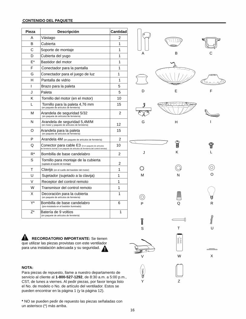
CONTENIDO DEL PAQUETE
Pieza Descripción CantidadA Vástago 2B Cubierta 1C Soporte de montaje 1D Cubierta del yugo 1E * Bastidor del motor 1F Conectador para la pantalla 1G Conectador para el juego de luz 1H Pantalla de vidrio 1I Brazo para la paleta 5J Paleta 5K Tornillo del motor (en el motor) 10L Tornillo para la paleta 4,76 mm 15 (en paquete de artículos de ferretería)
M Arandela de seguridad 5/32 2 (en paquete de artículos de ferretería)
N Arandela de seguridad 5,4M/M (en motor y paquete de artículos de ferretería) 12O Arandela para la paleta 15 (en paquete de artículos de ferretería)
P Arandela 4M (en paquete de artículos de ferretería) 2Q Conector para cable E3 (4 en paquete de artículos 10 de ferretería normal; 6 en paquete de artículos de ferretería del control remoto)
R * Bombilla de base candelabro 2S Tornillo para montaje de la cubierta (sujetado al soporte de montaje) 2T Clavija (en el cuello del bastidor del motor) 1U Sujetador (sujetado a la clavija) 1V Receptor del control remoto 1W Transmisor del control remoto 1X Decoración para la cubierta 1 (en paquete de artículos de ferretería)
Y * Bombilla de base candelabro 6 (pre-instalada en el bastidor iluminado)
Z* Batería de 9 voltios 1 (en paquete de artículos de ferretería)
RECORDATORIO IMPORTANTE: Se tienen que utilizar las piezas provistas con este ventilador para una instalación adecuada y su seguridad.
NOTA:Para piezas de repuesto, llame a nuestro departamento de servicio al cliente al 1-800-527-1292, de 8:30 a.m. a 5:00 p.m., CST, de lunes a viernes. Al pedir piezas, por favor tenga listo el No. de modelo o No. de artículo del ventilador. Estos se pueden encontrar en la página 1 (y la página 12).
* NO se pueden pedir de repuesto las piezas señaladas con un asterisco (*) más arriba.
A B C
D E F
G H I
J K L
M N O
P Q R
S T U
V W X
Y Z

17
Fig. 1
Fig. 2
Fig. 3
Fig. 4
INSTALACION INICIAL (continúa en la página siguiente) 1. Apague todos los cortacircuitos y el interruptor de pared a la línea de suministro de electricidad al ventilador. [Fig. 1] PELIGRO: El no desconectar el suministro de electricidad antes de la instalación puede resultar en daños graves o la muerte.
3. Asegúrese de que las paletas (J) del ventilador queden a por lo menos 30 pulgadas (76 cm) de cualquier obstrucción. Verifique la longitud del vástago (A) para asegurarse de que las paletas (J) queden a por lo menos 7 pies (2,13 m) arriba del nivel del piso. [Fig. 3]
2. Determine el método de montaje: [Fig. 2] A. Montaje normal B. Montaje en ánguloImportante: Cuando se usa el montaje en ángulo, asegúrese de que el ángulo del techo no tenga una inclinación mayor de 19°.
4. Asegure el soporte de montaje (C) a la caja de salida con los tornillos, las arandelas de resorte, y las arandelas planas provistos con la caja de salida. [Fig. 4] Es muy importante usar los artículos de ferretería correctos al instalar el soporte de montaje puesto que sirve para sostener el ventilador.
Importante: Si usa el montaje en ángulo, asegúrese de instalar el soporte de montaje (C) con la abertura orientada hacia el punto más alto del techo.
2,13 mmin.
0,76 mmin.
J
C
1. Antes de empezar con el ensamblaje e instalación del producto, asegúrese de tener todas las piezas. Compare las piezas con la lista y los diagramas del "Contenido del paquete" en la página anterior. Si falta alguna pieza o se encuentra dañada, no trate de ensamblar, instalar o hacer funcionar el producto. Póngase en contacto con el departamento de servicio al cliente para piezas de repuesto tal como se le indica al pie de la página 16.
Tiempo estimado para la instalación: 120 minutosHerramientas necesarias para el ensamblaje (no incluidas): cinta aislante, destornillador Phillips, alicate, gafas protectoras, escalera portátil y pela cablesHerramientas opcionales (no incluidas): lámpara probador CA, cinta de medir, guía de instalación eléctrica de hágalo usted mismo, disponible en Lowe's, y cortaalambresBombillas necesarias: 6 bombillas de base candelabro de 15 vatios máx. (incluidas), para el bastidor iluminado 2 bombillas de base candelabro de 60 vatios máx. (incluidas), para el juego de luz
2. Después de abrir la parte superior de la caja de cartón, saque el paquete de ferretería para montaje de las inserciones de goma espuma. Saque el motor del empaquetado y póngalo en la alfombra o sobre la goma espuma para evitar daño al acabado.
PRECAUCION: Cuidadosamente verifique que todos los tornillos, los pernos y las tuercas en el motor del ventilador están seguros.
PELIGRO: Cuando utilice una caja de salida existente, asegúrese de que la caja esté firmemente sujetada a la estructura del edificio para que pueda sostener el peso total del ventilador. El no hacer ésto puede resultar en graves daños o la muerte. La estabilidad de la caja de salida es esencial para minimizar tambaleo y ruido en el ventilador una vez que se haya terminado la instalación.
PRECAUCION: Asegúrese de que la caja de salida esté conectada a tierra correctamente y que haya un conductor a tierra (cable verde o pelado).
PREPARACION
B
A

18
3. Coloque el vástago (A) dentro del cuello del yugo del bastidor del motor, alinee el agujero y vuelva a instalar la clavija (T) y el sujetador (U). Ajuste los tornillos de fijación del vástago (A) y luego apriete las tuercas. Resbale la cubierta del yugo (D) hasta que se apoye en el bastidor del motor (E) [Fig. 3]
MONTAJE DEL VENTILADOR
4. Instale el extremo de la bola del vástago (A) en la abertura del soporte de montaje (C). Alinee la ranura de la bola con la lengüeta del soporte de montaje (C). [Fig. 4]
PELIGRO: El no alinear la lengüeta con la ranura de la bola puede ser causa de graves daños o de muerte.
1. Quite la clavija (T) y el sujetador (U) del yugo del bastidor del motor en la parte superior del bastidor del motor (E) y parcialmente afloje los tornillos de fijación. (Fig. 1)
*Consejo útil: El montaje con vástago es más adecuado para techos de 8 pies (2,44 m) o más altos. Para techos de mayor altura, quizás usted prefiera usar un vástago más largo (no incluido) de los provistos. El montaje en ángulo es más adecuado para techos en ángulo o abovedados. A veces se necesitarán vástagos más largos para asegurar el espacio adecuado para las paletas del ventilador.
2. Escoja el largo de vástago (A) que desea usar.* Si elige usar el vástago (A) de 30,48 cm, quite la bola que sirve para colgar del vástago (A) de 15,24 cm para usarla en el vástago (A) de 30,48 cm. Introduzca el vástago (A) en la cubierta (B), la decoración para la cubierta (X), y la cubierta del yugo (D). [Nota: Se tiene que voltear la decoración para la cubierta (X) para que el lado brillante dé al bastidor del motor (E).] Pase los cables del bastidor del motor (E) por el vástago (A). [Fig. 2]
Fig. 5
5. Saque los tornillos de montaje para los brazos para las paletas (K) y las arandelas de seguridad (N) del lado inferior del motor. Quite la placa de estabilización del motor de color azul y deséchela. [Fig. 5]
INSTALACION INICIAL (continúa de la página anterior)
Fig. 2
Fig. 4
D
D
E
T
B
U
A
A
Fig. 3
X
tornillo defijación
Fig. 1E
TU
C
bola
B
Alengüeta
ranura en la bola
NK
placa de estabilización
E

19
Fig. 1
Antena
V A
C
Fig. 3
3. Con cuidado meta el receptor (V), con el lado plano hacia arriba, en el soporte de montaje (C). Voltee los cables empalmados (que tienen cinta aislante) hacia arriba y con cuidado meta los cables/los conectores para cable (Q) dentro de la caja de salida. Deje la antena del receptor (V) a un lado fuera del soporte (C). [Fig. 3]
Nota: El control remoto incluido con este ventilador cumple con los requisitos siguientes: a. No para uso con ventiladores de estado sólido. b. Clasificación eléctrica: 120V / 60 Hz; amperaje MAX. del motor: 1,0; / vatios de luz: 300 (sólo incandescente)
CONEXION DE LOS CABLES DEL CONTROL REMOTO Y EL VENTILADOR
1. Haga las conexiones eléctricas necesarias para que pueda manejar el ventilador con el control remoto según la Fig. 1. Para cada conexión de cable que se va a hacer, use uno de los conectores para cable (Q) provistos, asegurándose de atornillar el conector para cable (Q) en el sentido de las agujas del reloj. [Asegúrese de conectar todos los CONDUCTORES A TIERRA (cables VERDES) del ventilador (en el vástago y el soporte de montaje) al cable PELADO/VERDE del techo.]CONSEJO AL HACER LAS CONEXIONES ELECTRICAS: El hacer las conexiones eléctricas para el control remoto del ventilador requiere mucha paciencia. Pare varias veces al estar haciendo las conexiones para descansar los brazos.
Nota: El cable negro es positivo (conduce energía eléctrica) del ventilador. El cable anaranjado es positivo (conduce energía eléctrica) del bastidor iluminado. El cable azul es positivo (conduce energía eléctrica) del juego de luz. El cable blanco es tanto para el ventilador como para el juego de luz. El cable verde es el que hace tierra.
Nota: Por favor refiérase a las instrucciones de instalación y funcionamiento para el control remoto.
2. Una los conectores para cable (Q) a los cables con cinta aislante. [Fig. 2]
Advertencia: Asegúrese de que no se vean cables pelados ni filamentos después de hacer las conexiones. Coloque las conexiones verdes y blancas en la caja al lado opuesto de las negras, anaranjadas y azules (si aplica).
PRECAUCION: Asegúrese de que la caja de salida esté conectada a tierra correctamente y que haya un conductor a tierra (cable verde o pelado).
ADVERTENCIA: Si los cables de la casa son de colores diferentes a los mencionados en los pasos siguientes, suspenda el trabajo inmediatamente Se recomienda que un electricista profesional determine la instalación eléctrica que se debe hacer.
ADVERTENCIA: Para reducir el riesgo de incendio, choque eléctrico o daño corporal, los conectores para cable provistos con este ventilador son diseñados para aceptar sólo un cable de calibre 12 de la casa y dos cables principales del ventilador. Si el calibre del cable de la casa es superior al 12 o hay más de un cable de la casa para conectar a los cables principales del ventilador, consulte con un electricista para informarse sobre el tamaño correcto de conectores para cable que se debe usar.
Q
del techo
negro
blanco
negro
blancoEntrada CA N
alambre conductor negro
alambre conductor blanco
V
antena
del ventiladordel receptor
Entrada CA L
toma detierra (verde
o pelada)
toma de tierra(verde o pelada)
del receptornegroblanco
azul
negroblanco
azul
anaranjado
anaranjado
Fig. 2

20
7. Instale las dos bombillas de base candelabro de 60 vatios máx. (R) incluidas. [Fig. 7]
Importante: Cuando necesite reemplazar las bombillas, por favor permita que se enfríen la(s) bombilla(s) y la pantalla de vidrio (H) antes de tocarlas.
INSTALACION FINAL (continúa en la página siguiente)
4. Coloque las arandelas de seguridad (N) e introduzca los tornillos para el motor (K) restantes. Repita con los demás brazos para las paletas (I). Apriete bien todos los tornillos del motor (K). [Fig. 4]
3. Localice tornillos del motor (K) y arandelas de seguridad (N) que se quitaron anteriormente en la pagina 5. (Tornillos del motor (K) y arandelas de seguridad (N) adicionales en paquete de artículos de ferretería). Introduzca un solo tornillo del motor (K), junto con la arandela de seguridad (N), en el brazo para la paleta (I) para sujetar el brazo para la paleta (I) al motor y apriete el tornillo (K) parcialmente. Repita con los demás brazos para las paletas (I). [Fig. 3]
2. Coloque el brazo para la paleta (I) debajo de la paleta (J) y asegure el brazo para la paleta (I) con tornillos (L) y arandelas (O). No apriete los tornillos (L) hasta que se haya colocado cada tornillo (L). Luego, apriete cada tornillo (L) empezando con el de en medio. Repita para las paletas (J) restantes. [Fig. 2]
1. Localice los dos tornillos para montaje de la cubierta (S) en la parte inferior del soporte de montaje (C) y quite el tornillo (S) que está localizado más cerca del extremo abierto del soporte de montaje (C). Afloje parcialmente el otro tornillo (S). Eleve la cubierta (B) hasta el soporte de montaje (C). Ponga la parte redondeada del agujero con ranura en la cubierta (B) encima del tornillo (S) aflojado en el soporte de montaje (C) y empuje hacia arriba. Gire la cubierta (B) para cerrarla. Vuelva a introducir el tornillo (S) que se quitó, y luego apriete bien ambos tornillos (S). Suba la decoración para la cubierta (X) hasta la cubierta (B), alineando la parte redondeada de los agujeros con ranura en la decoración para la cubierta (X) con las cabezas de tornillo en el fondo de la cubierta (B). Gire la decoración para la cubierta (X) a la derecha (en el sentido de las agujas del reloj) hasta que ya no gire. [Fig. 1]
6. Parcialmente afloje los dos tornillos en la parte inferior del conectador para la pantalla (F) y quite el otro tornillo. Conecte el cable BLANCO del conectador para el juego de luz (G) al cable BLANCO del bastidor del motor (E). Conecte el cable NEGRO del conectador para el juego de luz (G) al cable NEGRO del bastidor del motor (E). Asegúrese de que las conexiones tipo "molex" se cierren bien con un clic.
Cuidadosamente aregle los cables dentro del conectador para el juego de luz (G). Alinee los agujeros con ranura en el conectador para el juego de luz (G) con los tornillos aflojados en el conectador para la pantalla (F). Gire el conectador para el juego de luz (G) para cerrarlo. Vuelva a introducir el tornillo que se quitó y apriete bien todos los tornillos. [Fig. 6]
Fig. 2
Fig. 4
JI
E
Fig. 3
E
I/JK
N
J
I
LO
Fig. 1
AX
BS
Fig. 6
E
F
G
E
F
placa deconexión
Fig. 5
5. Quite un tornillo en la placa de conexión (en la parte inferior del motor) y afloje los otros dos tornillos. Alinee los agujeros con ranura en el conectador para la pantalla (F) con los tornillos aflojados en la placa de conexión. Gire el conectador para la pantalla (F) para cerrarlo y vuelva a instalar el tornillo que se quitó anteriormente. Apriete bien todos los tornillos. [Fig. 5]
Fig. 7
RF
E

cubierta de la batería
códigos de los conmutadores de las unidades del control remoto
bolígrafo
Fig. 8
E
F
H
21
8. Quite un tornillo de por dentro de la pantalla de vidrio (H) y afloje parcialmente los otros tres tornillos. Alinee los tres tornillos aflojados en la pantalla de vidrio (H) con los agujeros con ranura en el conectador para la pantalla (F). Gire el conectador para el juego de luz (G) para cerrarlo. Vuelva a introducir el tornillo que se quitó anteriormente y apriete bien los cuatro tornillos con destornillador Phillips. [Fig. 8]Consejo útil: Use un destornillador Phillips corto para poder tener acceso más fácil a los tornillos en el conectador para la pantalla (F).
INSTALACION FINAL (continúa de la página anterior)
PROCESO DE APRENDIZAJE AUTOMATICO/ACTIVANDO EL CODIGO
W Z
1
botón reductor de luz
PRECAUCION: Se puede programar el transmisor del control remoto (W) para usar con varios receptores o ventiladores. Si no desea hacer esto, apague el interruptor de pared de cualquier otro receptor o ventilador programable.
1. Quite la tapa de la batería de la parte de atrás del transmisor del control remoto (W).
2. Mueva los conmutadores de los códigos 1 a 4 a su elección hacia arriba o hacia abajo. (La programación de la fábrica viene todo para arriba. No use esta posición.) Use un destornillador pequeño o un bolígrafo para moverlos firmemente hacia arriba o hacia abajo. [Fig. 1]
3. Localice el botón reductor de luz a mano derecha de los conmutadores de códigos etiquetado con una “D” y “X”. [Fig. 1] Ponga el botón reductor de luz en la posición “ENCENDIDO” (D) solamente si usan bombillas incandescentes. Ponga el botón reductor de luz en la posición “APAGADO” (X) si usan bombillas fluorescentes compactas. NOTA: La mayoría de las bombillas fluorescentes compactas no son compatibles para uso con reductor de luz.
4. Instale la batería de 9 voltios (Z) provista.
5. Vuelva a conectar la electricidad. Dentro de 30 segundos de haber conectado la electricidad de nuevo, oprima el botón “FAN/OFF” en el transmisor del control remoto (W) por 5 segundos o hasta que la luz inferior parpadee dos veces. Ponga a prueba las funciones de luz y ventilador para confirmar que se haya acabado el proceso de aprendizaje. [Fig. 2]
6. Vuelva a poner la tapa de la batería en el transmisor (W). [Fig. 1]
IMPORTANTE: Para prevenir daño al transmisor del control remoto (W), saque la batería (Z) si no se usa por un tiempo extendido. Guarde el transmisor del control remoto (W) lejos del calor excesivo o la humedad.
El transmisor del control remoto (W) está equipado con 16combinaciones de códigos para prevenir posibles interferenciasde o a otras unidades de control remoto como abridores depuertas, alarmas de carro o sistemas de seguridad. Si encuentraque su ventilador y juego de luz se prenden y se apagan sin usarsu control, simplemente cambie el código de combinación delcontrol. Si cambia el código de combinación, desconecte elsuministro de fuerza eléctrica y repita los pasos 5 y 6 más arriba.
Fig. 1
Fig. 2
W
22
FUNCIONAMIENTO DEL CONTROL REMOTO Y EL VENTILADOR
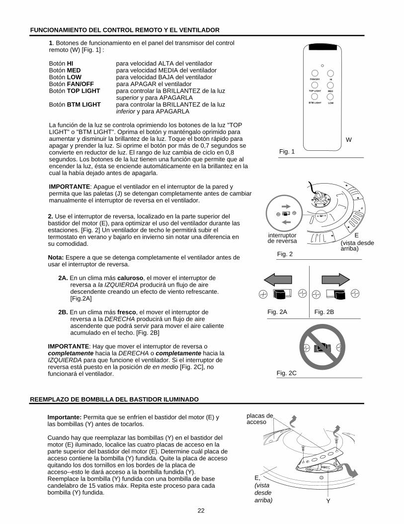
2. Use el interruptor de reversa, localizado en la parte superior del bastidor del motor (E), para optimizar el uso del ventilador durante las estaciones. [Fig. 2] Un ventilador de techo le permitirá subir el termostato en verano y bajarlo en invierno sin notar una diferencia en su comodidad.
Nota: Espere a que se detenga completamente el ventilador antes de usar el interruptor de reversa.
2A. En un clima más caluroso, el mover el interruptor de reversa a la IZQUIERDA producirá un flujo de aire descendente creando un efecto de viento refrescante. [Fig.2A]
2B. En un clima más fresco, el mover el interruptor de reversa a la DERECHA producirá un flujo de aire ascendente que podrá servir para mover el aire caliente acumulado en el techo. [Fig. 2B]
IMPORTANTE: Hay que mover el interruptor de reversa o completamente hacia la DERECHA o completamente hacia la IZQUIERDA para que funcione el ventilador. Si el interruptor de reversa está puesto en la posición de en medio [Fig. 2C], no funcionará el ventilador.
W
Fig. 1
1. Botones de funcionamiento en el panel del transmisor del control remoto (W) [Fig. 1] :
Botón HI para velocidad ALTA del ventiladorBotón MED para velocidad MEDIA del ventiladorBotón LOW para velocidad BAJA del ventiladorBotón FAN/OFF para APAGAR el ventilador Botón TOP LIGHT para controlar la BRILLANTEZ de la luz superior y para APAGARLABotón BTM LIGHT para controlar la BRILLANTEZ de la luz inferior y para APAGARLA
La función de la luz se controla oprimiendo los botones de la luz "TOP LIGHT" o "BTM LIGHT". Oprima el botón y manténgalo oprimido para aumentar y disminuir la brillantez de la luz. Toque el botón rápido para apagar y prender la luz. Si oprime el botón por más de 0,7 segundos se convierte en reductor de luz. El rango de luz cambia de ciclo en 0,8 segundos. Los botones de la luz tienen una función que permite que al encender la luz, ésta se enciende automáticamente en la brillantez en la cual la había dejado antes de apagarla.
IMPORTANTE: Apague el ventilador en el interruptor de la pared y permita que las paletas (J) se detengan completamente antes de cambiar manualmente el interruptor de reversa en el ventilador.
REEMPLAZO DE BOMBILLA DEL BASTIDOR ILUMINADO
Y
placas deacceso
Importante: Permita que se enfríen el bastidor del motor (E) y las bombillas (Y) antes de tocarlos.
Cuando hay que reemplazar las bombillas (Y) en el bastidor del motor (E) iluminado, localice las cuatro placas de acceso en la parte superior del bastidor del motor (E). Determine cuál placa de acceso contiene la bombilla (Y) fundida. Quite la placa de acceso quitando los dos tornillos en los bordes de la placa de acceso--esto le dará acceso a la bombilla fundida (Y). Reemplace la bombilla (Y) fundida con una bombilla de base candelabro de 15 vatios máx. Repita este proceso para cada bombilla (Y) fundida.
E,(vista desde arriba)
Fig. 2
Fig. 2A Fig. 2B
Fig. 2C
interruptorde reversa (vista desde
arriba)
E

LOCALIZACION DE FALLAS (continúa en la página siguiente)
23
Problema Causa posible Acción correctivaEl ventilador no se mueve. 1. El interruptor de reversa no está 1. Mueva el interruptor firmemente hacia prendido. la derecha o hacia la izquierda. 2. No hay electricidad o se ha saltado un 2. Conecte la electricidad o inspeccione fusible. el fusible. 3. Conexión de cables defectuosa. 3. Apague la electricidad. Afloje la cubierta (B) e inspeccione todas las conexiones. 4. No se conectaron bien los enchufes. 4. Verifique que se conectaron bien los enchufes macho y hembra en el conectador para el juego de luz (G) según las instrucciones en la página 20. Funcionamiento ruidoso. 1. Las paletas (J) están flojas. 1. Apriete todos los tornillos para las paletas (L). 2. Paleta (J) rota. 2. Reemplace la paleta (J). 3. El ventilador es nuevo. 3. Permita unos días para que el motor del ventilador se equilibre, epecialmente al usar el ventilador a velocidad media o alta.Tambaleo excesivo. 1. Las paletas (J) están flojas. 1. Apriete todos los tornillos para las paletas (L). 2. No se instalaron correctamente los 2. Instale los brazos para las paletas (I) brazos para las paletas (I). de nuevo. 3. Las paletas (J) no están equilibradas. 3. Intercambie una paleta (J) con otra del lado contrario. 4. El ventilador no está sujetado bien. 4. Apague la electricidad. Afloje la cubierta (B) cuidadosamente y verifique que el soporte de montaje (C) esté bien sujeto. 5. El ventilador está demasiado cerca de 5. Utilice un vástago (A) más largo o un techo abovedado. mueva el ventilador a otro lugar. 6. No se apretó (apretaron) bien el (los) 6. Apriete bien el (los) tornillo(s) de tornillo(s) de fijación en el yugo del fijación. bastidor del motor. 7. No se apretó bien el tornillo de fijación 7. Afloje la cubierta (B) y bájela cuidado- en la bola que sirve para colgar. samente y verifique que esté bien apretado el tornillo de fijación en la bola que sirve para colgar.El ventilador funciona pero 1. No se instalaron bien las bombillas. 1. Instale las bombillas de nuevo.las luces no. 2. No se conectaron correctamente los 2. Verifique que se conectaron bien(continúa en la página cables en la cubierta (B). los cables en la cubierta (B) y, si essiguiente) necesario, vuelva a conectarlos según las instrucciones en la página 19.
Advertencia: Antes de empezar cualquier trabajo, corte el suministro de electricidad para evitar un choque eléctrico.
CUIDADO Y MANTENIMIENTO
Baje Ia cubierta (B) para inspeccionar el conjunto del vástago (A) por lo menos dos veces al año, y luego apriete todos los tornillos del ventilador. Limpie el bastidor del ventilador (E) solamente con un cepillo suave o un paño que no tenga pelusa para no rayar el acabado. Limpie las paletas (J) con un paño que no tenga pelusa. De vez en cuando usted puede lustrar las paletas de madera con un poco de cera para muebles como una protección adicional.Importante: Apague la fuente principal del suministro de electricidad antes de iniciar cualquier tipo de mantenimiento. No use agua ni un paño húmedo para limpiar el ventilador.
Impreso en China24
GARANTIA
GARANTIA LIMITADA DE POR VIDA: Litex Industries garantiza que este ventilador está libre de defectos de mano de obra y de materiales desde la fecha de salida de la fábrica por el tiempo de por vida limitada a partir de la fecha de compra. Esta garantía sólo se aplica al comprador original. Litex Industries se compromete a corregir cualquier defecto libre de cargo o, si lo considera necesario, a reemplazar el ventilador por un modelo equiparable o superior.
Para recibir servicio durante el período de garantía, debe presentar una copia del recibo como comprobante de compra. Cualquier costo derivado de la remoción y la re-instalación será responsabilidad explícita del comprador. Cualquier daño accidental al ventilador o por uso inadecuado o instalación incorrecta o por usar piezas no producidas por el fabricante de este ventilador o por la fijación de accesorios no producidos por el fabricante de este ventilador, será la responsabilidad del comprador. Litex Industries no se hace responsable en ningún modo de la instalación del ventilador durante el período de garantía limitada de por vida. Cualquier servicio prestado por una persona no autorizada invalida la garantía.
Debido a los distintos tipos de condiciones climáticas, esta garantía no cubre ningún cambio en el acabado bronce, ni por la oxidación, marcas, la decoloración, la corrosión ni el descascarillado del material. Se conserva la belleza de un ventilador con acabado bronce protegiéndolo de las diversas condiciones de clima. Las pantallas provistas con el ventilador no están cubiertas por la garantía.
Cualquier pieza defectuosa del ventilador de techo se debe reportar dentro del primer año desde la fecha de compra. Si desea que reparemos o reemplacemos su ventilador, llame a nuestro departamento de servicio al cliente (al 1-800-527-1292) para obtener una autorización de devolución e instrucciones de envío. Cualquier ventilador o pieza devuelta en malas condiciones de empaquetamiento será la responsabilidad única del comprador. No existe ninguna otra garantía expresa. Litex Industries rehusa cualquier y toda garantía implícita. La duración de cualquier garantía implícita a la que no se pueda renunciar se limita al tiempo de por vida especificado en nuestra garantía limitada. Litex Industries no es responsable de daños incidentales, emergentes ni especiales surgidos de o con respecto al uso o el funcionamiento del producto, salvo previo acuerdo con la ley. Esta garantía le da derechos legales específicos y es posible que usted también tenga otros derechos que pueden variar de estado en estado. Esta garantía reemplaza toda garantía previa.
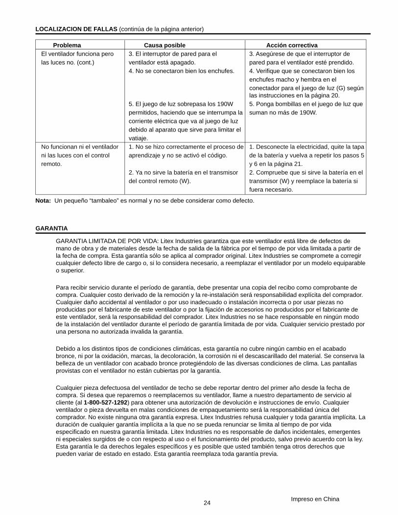
Problema Causa posible Acción correctivaEl ventilador funciona pero 3. El interruptor de pared para el 3. Asegúrese de que el interruptor delas luces no. (cont.) ventilador está apagado. pared para el ventilador esté prendido. 4. No se conectaron bien los enchufes. 4. Verifique que se conectaron bien los enchufes macho y hembra en el conectador para el juego de luz (G) según las instrucciones en la página 20. 5. El juego de luz sobrepasa los 190W 5. Ponga bombillas en el juego de luz que permitidos, haciendo que se interrumpa la suman no más de 190W. corriente eléctrica que va al juego de luz debido al aparato que sirve para limitar el vatiaje.No funcionan ni el ventilador 1. No se hizo correctamente el proceso de 1. Desconecte la electricidad, quite la tapani las luces con el control aprendizaje y no se activó el código. de la batería y vuelva a repetir los pasos 5remoto. y 6 en la página 21. 2. Ya no sirve la batería en el transmisor 2. Compruebe que si sirve la batería en el del control remoto (W). transmisor (W) y reemplace la batería si fuera necesario.
LOCALIZACION DE FALLAS (continúa de la página anterior)
Nota: Un pequeño “tambaleo” es normal y no se debe considerar como defecto.