Montazni navod TW A3 · 2018-10-22 · Montážní návod Assembly manual Montageanleitung...
2
Montážní návod Assembly manual Montageanleitung Instrukcja montażu Instrucțiuni de montaj Střešní vpust Roof Outlet Dachgully Wpust dachowy Guri de scurgere pentru acoperiș TW DN/OD S TWE DN/OD S TW DN/OD V TWE DN/OD V 1. Montážní návod pro střešní vpusti 1.1 Příprava podkladu Svislou i vodorovnou střešní vpust TOPWET lze osadit do předem připraveného nebo dodatečně provedeného otvo- ru v podkladní konstrukci nebo tepelné izolaci. Minimální rozměry otvoru jsou uvedeny na zadní straně návodu (ob- rázek 3.1). Horní líc příruby je vhodné osadit tak, aby vpust byla minimálně o 5-10 mm níže než navazující povrch pod- kladní vrstvy. Vpust musí být osazena tak, aby obvodová příruba ležela na okraji otvoru, v případě potřeby se hrany okraje otvoru musí zkosit. 1.2 Kotvení střešní vpusti TOPWET Vpust osazená do betonové nosné konstrukce se me- chanicky ukotví pomocí kotevních šroubů a volný prostor otvoru mezi vpustí a stropní konstrukcí se vyplní tepelnou izolací nebo montážní polyuretanovou pěnou, která slouží k fixaci vpusti a zároveň jako tepelná izolace. Do podkladů na bázi dřeva (prkenné bednění, OSB desky, překližka) se vpusti mechanicky kotví pomocí kotevních šroubů. V případě podkladu z trapézového plechu je vhodné v mís- tě otvoru nejdříve přikotvit podkladní vyrovnávací plech (rozměr cca 400 x 400 mm), následně vyříznout otvor, vpust osadit a mechanicky ukotvit do horní vlny trapézového ple- chu přes plech podkladní. 1.3 Napojení střešní vpusti na dešťové odpadní potrubí Před vlastním osazením střešní vpusti do hrdla dešťového odpadního potrubí se musí do kruhové drážky hrdla vložit pryžový těsnící kroužek. Před zasunutím střešní vpusti do dešťového odpadního potrubí se spodní okraj střešní vpus- ti natře kluzným prostředkem. Vsunutím střešní vpusti přes těsnící kroužek do drážky deš- ťového odpadního potrubí je zaručena vzájemná těsnost a propojení. 1.4 Napojení střešní vpusti na hlavní hydroizolační vrstvu, nebo parozábranu Napojení vpusti TOPWET na hydroizolační vrstvu se pro- vádí pomocí integrované manžety, nejčastěji z asfaltového pásu nebo mPVC fólie, TPO-FPO fólie, EPDM apod. (viz obrázek 3.2). Napojení integrované manžety střešní vpusti z asfaltové- ho pásu na hydroizolační vrstvu střechy ze souvrství dvou asfaltových pásů se provádí celoplošným natavením man- žety mezi dvě vrstvy hydroizolačního souvrství. Vzájemný přesah je min. 120 mm, manžeta je vložena mezi dva pásy tak, aby výsledný spoj byl „po vodě“. V případě jednovrst- vé hydroizolace z asfaltového pásu je nutné detail napojení vpusti na hydroizolaci doplnit o přídavný podkladní asfal- tový pás. Při natavování asfaltových pásů hrozí riziko poškození hor- ní plastové příruby plamenem. Je zapotřebí na horní příru- bu položit ochranný kryt příruby aby nedošlo k poškození příruby vpusti plamenem (ochranný kryt příruby je součástí balení každé vpusti s integrovanou bitumenovou manže- tou). Ochranný kryt příruby je současně vhodné použít jako šablonu pro vyříznutí otvoru do asfaltového pásu v místě vpusti. Takto napojená vpust na parozábranu z asfaltového pásu může sloužit po dobu výstavby objektu jako provizorní hyd- roizolační vrstva. Napojení integrované manžety střešní vpusti z mPVC fó- lie se na hydroizolační vrstvu střechy horkovzdušně na- vaří tak, aby výsledný spoj byl „po vodě“. Šířka svaru by měla být min. 30 mm, napojení hydroizolace na manžetu je vhodné doplnit pojistnou zálivkovou hmotou. V případě vpusti s integrovanou manžetou z PE fólie (nej- častěji používanou u lehkých střech jako parozábrana) se napojení v ploše provádí pomocí oboustranné butylkau- čukové lepicí pásky a následného přitlačení spoje. 1.5 Ochranný koš Ochranný koš je součástí každého balení vpusti TOPWET a díky univerzální konstrukci jej lze použít jak pro vpusti, tak pro nástavce. Ochranný koš musí být vždy osazen, aby bránil vplavování hrubých nečistot do odpadního potrubí a zamezil tak jeho ucpání. U střešních plášťů opatřených stabilizační vrstvou z násypu kameniva je nutné použít speciální nerezový ochranný koš TOPWET pro střechy s kačírkem. Výška tohoto košíku musí být zvolena tak, aby horní úroveň košíku byla min. 40 mm nad horní úrovní násypu kameniva. Ve vzdálenosti do 500 mm kolem vpusti je nutné použít kamenivo frakce 16/32. V případě vegetačních střech je nutné umožnit kontrolu a údržbu vpustí použitím speciální šachty TOPWET pro ze- lené střechy. Šachty čtvercového rozměru 300 x 300 mm nebo 400 x 400 mm vytvoří volný přístup kolem vpustí a zároveň zajistí jeho ochranu. Vlastní šachta se doplní ob- sypem min. šíře 300 mm z kameniva frakce 16/32. 1.6 Údržba a čištění střešních vpustí Pro zajištění spolehlivé funkčnosti výrobků je nutné nejmé- ně 2x ročně kontrolovat a čistit střešní vpust, ochranný koš, terasový nástavec, zápachovou klapku a jiné příslušenství. V případě nebezpečí častějšího zanášení (listí z okolních stromů apod.) je nutné intenzitu kontrol navýšit. 1. Assembly manual for roof outlets 1.1 Substrate preparation The vertical as well as horizontal TOPWET roof outlet can be installed into a prepared or additionally drilled hole in the base structure or thermal insulation. The minimum di- mensions of the hole are specified on the rear side of the manual (Picture 3.1). It is recommended to install the upper edge of the flange in a way that the outlet is at least 5mm to 10mm lower than the adjoining surface of the base layer. The outlet shall be installed in a way that the perimeter flange lays on the edge of the hole. If necessary, the edges of the hole should be bevelled. 1.2 Fixing TOPWET roof outlets Outlet installed in a concrete substrate shall be mecha- nically fixed using a suitable fixing. The free space of the opening between the outlet and the ceiling structure shall be filled with thermal insulation or assembly polyurethane foam (expanding foam), which is used for fastening the out- let and, at the same time, as thermal insulation. Outlets are mechanically fixed into plywood, timber or OSB decks using the appropriate fixing. For profiled metal decks, it is recommended to fix a base levelling plate (dimensions of approximately 400 x 400 mm) at the opening location first. This should be followed by cutting a hole, installing the outlet and mechanically fixing it to the upper corrugation of the metal deck over the base plate. 1.3 Connecting roof outlets to the rainwater waste pipe Prior to the actual installation of roof outlets into the neck of the rainwater waste pipe, a rubber sealing ring has to be placed in the round groove of the neck. The bottom edge of the roof outlet should be coated with a lubricant prior to inserting the roof outlet in the rainwater waste pipe. Mutual tightness and connection is secured by inserting the roof outlet / terrace outlets / balcony outlet via a sealing ring to the groove of the rainwater waste pipe. 1.4 Connecting roof outlets to the main waterpro- ofing layer or vapour barrier Connections of TOPWET outlets to the waterproofing layer are conducted using an integrated sleeve, most of- ten made of an asphalt strip or U-PVC foil, TPO-FPO foil, EPDM, etc. (see Picture 3.2). Connection of the integrated sleeve of the roof outlet from an asphalt strip to the waterproofing layer of the roof from the strata of two-layer asphalt strips is implemented by pla- cing the sleeve in between the two layers of the hydro-in- sulation strata. The mutual overlap is at least 120 mm. The sleeve is inserted in between the strips in a way that the final connection is “in the direction of the water flow”. For a single-layer hydro-insulation made of an asphalt strip, the detail of the connection of the outlet to hydro-insulation needs to be amended by an additional asphalt base strip. When melting asphalt strips, there is a risk of damaging the upper plastic flange by the flame. A protection cover needs to be applied to the upper flange in order to prevent outlet damages caused by the flame (the protection cover of the flange forms a part of every outlet package with an integrated bitumen sleeve). It is recommended to also use the protection cover of the flange for cutting off the opening in the asphalt strip at the outlet location. An outlet connected in this manner to the vapour barrier, made of an asphalt strip, can serve as a temporary hydro -insulation layer during the building construction process. Connection of the integrated sleeve of the roof outlet made of PVC foil is hot-air welded to the hydro-insulation layer of the roof, making sure the resulting connection is “in the direction of the water flow”. The weld gap should be at least 30 mm. It is recommended to amend the connection of hydro-insulation to the sleeve by a safety grout matter. For an outlet with an integrated sleeve made of PE foil (mainly used for light roofs as a vapour barrier), the sur- face connection is implemented by using a two-sided bu- tyl-rubber tape and by subsequently applying pressure to the connection. 1.5 Protection basket A protection basket forms a part of every TOPWET outlet package and, due to its universal design, can be used for outlets as well as extensions. A protection basket must be always installed in order to eliminate coarse dirt particles from entering the sewer pipes, thus preventing their plu- gging. For roof coverings with pebble ballast, a special stainless steel TOPWET protection basket should be used. The hei- ght of this basket shall be selected in a way that the upper level of the basket is at least 40mm above the upper level of the gravel aggregate. A pebble ballast aggregate of 20 mm to 40 mm grade should be used within 500 mm around the outlets. For sedum roofs, inspections and maintenance of the out- lets have to be enabled by the means of using a special TOPWET shaft for green roofs. Shafts of 300 mm x 300 mm or 400 mm x 400 mm will create a free access around the outlets and, at the same time will secure their protection. A pebble ballast packing will be applied to the shaft itself. It should be at least 300 mm wide, and typically 20 mm to 40 mm grade ballast. 1.6 Maintenance and cleaning of roof outlets In order to secure reliable operation of the products, it is necessary to inspect and clean roof outlets, protection baskets, terrace extensions, odour flap and other ac- cessories at least twice a year. If the risk of plugging is con- sidered greater (such as leaves from surrounding trees), the frequency of the inspections should be increased. 1. Montageanleitung für Dachabläufe 1.1 Vorbereitung der Untergrundfläche Der vertikale sowie auch horizontale Dachablauf von TOPWET ist in der im Vorfeld vorbereiteten bzw. nachträg- lich erfolgten Öffnung in der Untergrundkonstruktion oder Wärmeisolierung einzusetzen. Die Mindestmaße für die Öffnung sind auf der Rückseite der Anleitung angegeben (Abbildung 3.1). Die Flanschoberseite ist geeigneterwei- se in der Form einzusetzen, dass der Ablauf mindestens 5-10 mm niedriger als die sich anschließende Unter- grundschicht-Oberfläche ist. Der Ablauf ist in der Form ein- zusetzen, dass sich der Umfangsflansch am Öffnungsrand befindet. Bei Bedarf müssen die Kanten vom Öffnungsrand abgekantet werden. 1.2 Verankerung des Dachablaufs von TOPWET Der in der Betonträgerkonstruktion eingesetzte Ablauf wird mit Ankerschrauben mechanisch verankert. Der freie Öffnungsbereich zwischen dem Ablauf und der Dachkon- struktion wird mit Wärmeisolierung oder Montage-Polyu- rethanschaum gefüllt, welcher zu Fixierungszwecken des Ablaufs sowie gleichzeitig als Wärmeisolierung dient. Auf den Untergrundflächen auf Holzbasis (Bretterverscha- lung, OSB-Platten, Furnierplatten) werden die Abläufe mit Ankerschrauben mechanisch verankert. Bei einer Untergrundfläche aus Trapezblech ist es ratsam, zunächst das Ausgleichsblech für den Untergrund (Maße ca. 400 x 400 mm) an der Öffnungsstelle zu verankern sowie anschließend die Öffnung auszuschneiden, den Ablauf einzusetzen und über das Untergrundblech mecha- nisch an der oberen Welle des Trapezbleches zu verankern. 1.3 Anschluss des Dachablaufs am Regenfallrohr Bevor das eigentliche Einsetzen des Dachablaufs im Hals des Regenfallrohrs erfolgt, muss ein Gummidichtungsring in der Halsringnut eingelegt werden. Bevor der Dachablauf in das Regenfallrohr geschoben wird, ist der untere Rand des Dachablaufs mit einem Gleitmittel zu versehen. Die gegenseitige Verbindung sowie Dichtigkeit ist gewähr- leistet, wenn der Dachablauf durch den Dichtungsring in die Nut des Regenfallrohrs geschoben wird. 1.4 Anschluss des Dachablaufs an die Haupt-Hyd- roisolationsschicht bzw. an die Dampfsperre Der Anschluss des Ablaufs von TOPWET an die Haupt -Hydroisolationsschicht erfolgt mit einer integrierten Man- schette, welche meistens aus Bitumenstreifen bzw. aus mPVC-Folie, TPO-FPO-Folie, EPDM, etc. besteht (siehe Abbildung 3.2). Der Anschluss der integrierten Manschette des Da- chablaufs aus Bitumenstreifen an die Dach-Hydroisola- tionsschicht, welche aus einer Schichtenfolge von zwei Bitumenstreifen besteht, erfolgt durch ganzflächiges Schmelzen der Manschette zwischen den zwei Hydroiso- lationsschichten der Schichtenfolge. Der gegenseitige Überstand beträgt mindestens 120 mm. Die Manschette wird in der Form zwischen den zwei Streifen eingefügt, dass sich die finale Verbindung „über dem Wasser“ befin- det. Bei einer einschichtigen Hydroisolation aus Bitumen- streifen muss das Detail für den Anschluss des Ablaufs an die Hydroisolation mit einem zusätzlichen Bitumenstreifen ergänzt werden. Beim Schmelzen der Bitumenstreifen besteht die Gefahr, dass der obere Kunststoffflansch durch die Flammen be- schädigt wird. Aus diesem Grund ist der obere Flansch mit einer Flansch-Schutzabdeckung zu versehen, damit der Ablaufflansch nicht durch die Flammen beschädigt wird (die Flansch-Schutzabdeckung gehört zum Bestandteil des Packungsinhalts jedes Ablaufs mit integrierter Bitumen- manschette). Die Flansch-Schutzabdeckung kann auch gleichzeitig als Schablone zum Ausschneiden der Öffnung im Bitumenstreifen an der Ablaufstelle verwendet werden. Der auf diese Weise an die aus Bitumenstreifen bestehen- de Dampfsperre angeschlossene Ablauf kann während der Errichtung des Objekts auch als provisorische Hydroisola- tionsschicht dienen. Der Anschluss der integrierten Manschette des Dachab- laufs von der mPVC-Folie aus an die Dach-Hydroisola- tionsschicht erfolgt im Heißluftschweißverfahren in der Form, dass sich die finale Verbindung „über dem Wasser“ befindet. Die Breite der Schweißnaht sollte mindestens 30 mm betragen. Es ist ratsam, den Hydroisolationsanschluss an der Manschette mit einer Verschluss-Gussmasse zu er- gänzen. Bei einem Ablauf mit integrierter Manschette aus PE-Folie (wird bei am häufigsten bei Leichtdächern als Dampfsperre verwendet) erfolgt der Anschluss in der Fläche mit einem beidseitigen Butylkautschuk-Klebeband und dem an- schließenden Zusammendrücken der Verbindung. 1.5 Schutzgitter Das Schutzgitter gehört zum Bestandteil des Packungsin- halts jedes Ablaufs von TOPWET. Aufgrund der universel- len Konstruktion kann es sowohl für Abläufe als auch für Aufsätze verwendet werden. Ein Schutzgitter muss immer eingesetzt werden, damit kein grober Schmutz in das Re- genfallrohr gelangt und somit verhindert wird, dass dieses verstopft. Bei einer Dachhaut, welche mit einer stabilisierenden Spli- ttschicht versehen ist, ist das rostfreie Spezialgitter von TOPWET für Dächer mit Kieselsteinen zu verwenden. Die Höhe dieses Gitters ist in der Form zu wählen, dass sich die obere Gitterebene mindestens 40 mm über der oberen Splittschichtebene befindet. In einem Abstand von 500 mm um den Ablauf ist Splitt in der Fraktion 16/32 zu verwen- den. Bei Dachbegrünungen ist die Kontrolle sowie Wartung der Abläufe durch die Verwendung des Spezialschachts von TOPWET für Dachbegrünungen zu ermöglichen. Die quadratischen Schächte in einer Größe von 300 x 300 mm oder 400 x 400 mm bilden um den Ablauf einen freien Zu- gang und gewährleisten gleichzeitig dessen Schutz. Der eigentliche Schacht wird mit einer Schüttung mit einer Mindestbreite von 300 mm gefüllt, welche aus Splitt in der Fraktion 16/32 besteht. 1.6 Wartung und Reinigung der Dachabläufe Damit die zuverlässige Funktion der Produkte gewährleis- tet ist, sind der Dachablauf sowie das Schutzgitter, der Terrassenaufsatz, der Geruchsverschluss und das sonstige Zubehör mindestens 2x jährlich zu kontrollieren und zu reinigen. Sofern die Gefahr einer häufigeren Verstopfung besteht (Blätter von den umstehenden Bäumen, etc.), ist die Kontrollintensität entsprechend zu erhöhen. 1. Instrukcja montażu wpustów dachowych 1.1 Przygotowanie podłoża Zarówno pionowy, jak i poziomy wpust dachowy TOPWET można zamontować we wcześniej przygotowanym albo dodatkowo wykonanym otworze w konstrukcji podłoża lub izolacji termicznej. Minimalne wymiary otworu przedsta- wiono na tylnej stronie instrukcji (rysunek 3.1). Zaleca się takie usytuowanie górnego lica kołnierza, aby wpust zna- jdował się co najmniej o 5–10 mm poniżej otaczającej go powierzchni warstwy podkładowej. Wpust należy umieścić w taki sposób, aby kołnierz zewnętrzny leżał na krawędzi otworu, w razie potrzeby krawędzie otworu należy sfazo- wać. 1.2 Mocowanie wpustu dachowego TOPWET Wpust umieszczony w betonowej konstrukcji nośnej należy mocować mechanicznie przy pomocy śrub kotwiących, wolną przestrzeń otworu między wpustem i konstrukcją stropu należy wypełnić izolacją termiczną lub montażową pianką poliuretanową, która służy zarówno do mecha- nicznego usztywnienia wpustu, jak i jego termoizolacji. Do podłoży na bazie drewna (deskowanie drewniane, płyty OSB, sklejka) wpusty należy mocować mechanicznie przy pomocy śrub kotwiących. W przypadku podłoża wykonanego z blachy trapezowej zalecana procedura mocowania polega na tym, że w pi- erwszej kolejności w miejscu otworu należy zamocować podkładową blachę wyrównującą (o wymiarach mniej wię- cej 400×400 mm), następnie wyciąć otwór, umieścić wpust i przytwierdzić go mechanicznie do górnej fali blachy trape- zowej przez blachę podkładową. 1.3 Podłączenie wpustu dachowego do deszc- zowej rury spustowej Zanim wpust dachowy zostanie ostatecznie umieszczony w kielichu deszczowej rury spustowej, do rowka pierści- eniowego w kielichu należy włożyć gumowy pierścień uszczelniający. Przed wsunięciem wpustu dachowego do deszczowej rury spustowej dolną krawędź wpustu da- chowego należy posmarować środkiem poślizgowym. Wsunięcie wpustu dachowego w deszczową rurę spus- tową z rowkiem zawierającym pierścień uszczelniający gwarantuje wzajemną szczelność i poprawność połącze- nia. www.topwet.cz www.topwet.cz www.topwet.cz 3 4 2 BIT PVC
Transcript of Montazni navod TW A3 · 2018-10-22 · Montážní návod Assembly manual Montageanleitung...
Montážní návodAssembly manualMontageanleitungInstrukcja montażuInstrucțiuni de montaj
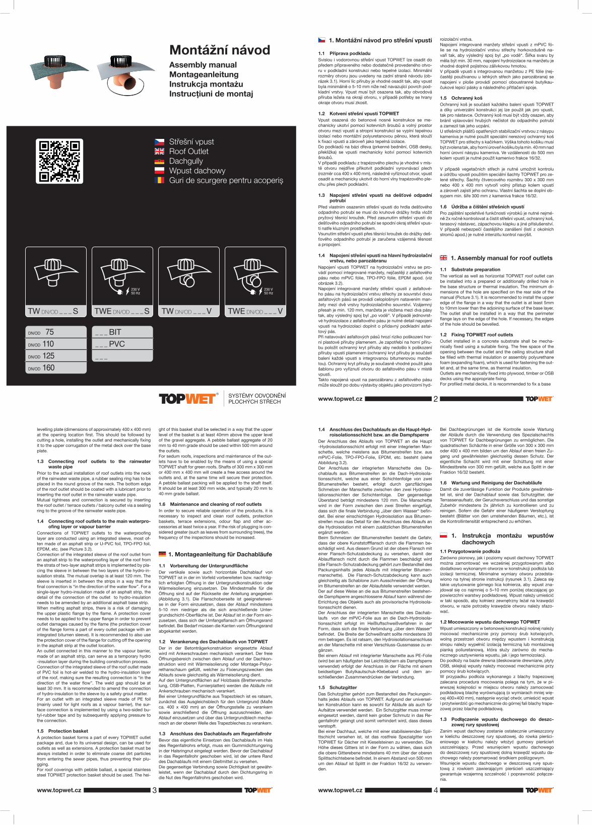
Střešní vpustRoof OutletDachgullyWpust dachowyGuri de scurgere pentru acoperiș
TW DN/OD S TWE DN/OD S TW DN/OD V TWE DN/OD V
1. Montážní návod pro střešní vpusti
1.1 Příprava podkladuSvislou i vodorovnou střešní vpust TOPWET lze osadit do předem připraveného nebo dodatečně provedeného otvo-ru v podkladní konstrukci nebo tepelné izolaci. Minimální rozměry otvoru jsou uvedeny na zadní straně návodu (ob-rázek 3.1). Horní líc příruby je vhodné osadit tak, aby vpust byla minimálně o 5-10 mm níže než navazující povrch pod-kladní vrstvy. Vpust musí být osazena tak, aby obvodová příruba ležela na okraji otvoru, v případě potřeby se hrany okraje otvoru musí zkosit.
1.2 Kotvení střešní vpusti TOPWETVpust osazená do betonové nosné konstrukce se me-chanicky ukotví pomocí kotevních šroubů a volný prostor otvoru mezi vpustí a stropní konstrukcí se vyplní tepelnou izolací nebo montážní polyuretanovou pěnou, která slouží k fi xaci vpusti a zároveň jako tepelná izolace.Do podkladů na bázi dřeva (prkenné bednění, OSB desky, překližka) se vpusti mechanicky kotví pomocí kotevních šroubů.V případě podkladu z trapézového plechu je vhodné v mís-tě otvoru nejdříve přikotvit podkladní vyrovnávací plech (rozměr cca 400 x 400 mm), následně vyříznout otvor, vpust osadit a mechanicky ukotvit do horní vlny trapézového ple-chu přes plech podkladní.
1.3 Napojení střešní vpusti na dešťové odpadní potrubí
Před vlastním osazením střešní vpusti do hrdla dešťového odpadního potrubí se musí do kruhové drážky hrdla vložit pryžový těsnící kroužek. Před zasunutím střešní vpusti do dešťového odpadního potrubí se spodní okraj střešní vpus-ti natře kluzným prostředkem.Vsunutím střešní vpusti přes těsnící kroužek do drážky deš-ťového odpadního potrubí je zaručena vzájemná těsnost a propojení.
1.4 Napojení střešní vpusti na hlavní hydroizolační vrstvu, nebo parozábranu
Napojení vpusti TOPWET na hydroizolační vrstvu se pro-vádí pomocí integrované manžety, nejčastěji z asfaltového pásu nebo mPVC fólie, TPO-FPO fólie, EPDM apod. (viz obrázek 3.2).Napojení integrované manžety střešní vpusti z asfaltové-ho pásu na hydroizolační vrstvu střechy ze souvrství dvou asfaltových pásů se provádí celoplošným natavením man-žety mezi dvě vrstvy hydroizolačního souvrství. Vzájemný přesah je min. 120 mm, manžeta je vložena mezi dva pásy tak, aby výsledný spoj byl „po vodě“. V případě jednovrst-vé hydroizolace z asfaltového pásu je nutné detail napojení vpusti na hydroizolaci doplnit o přídavný podkladní asfal-tový pás.Při natavování asfaltových pásů hrozí riziko poškození hor-ní plastové příruby plamenem. Je zapotřebí na horní příru-bu položit ochranný kryt příruby aby nedošlo k poškození příruby vpusti plamenem (ochranný kryt příruby je součástí balení každé vpusti s integrovanou bitumenovou manže-tou). Ochranný kryt příruby je současně vhodné použít jako šablonu pro vyříznutí otvoru do asfaltového pásu v místě vpusti.Takto napojená vpust na parozábranu z asfaltového pásu může sloužit po dobu výstavby objektu jako provizorní hyd-
roizolační vrstva.Napojení integrované manžety střešní vpusti z mPVC fó-lie se na hydroizolační vrstvu střechy horkovzdušně na-vaří tak, aby výsledný spoj byl „po vodě“. Šířka svaru by měla být min. 30 mm, napojení hydroizolace na manžetu je vhodné doplnit pojistnou zálivkovou hmotou.V případě vpusti s integrovanou manžetou z PE fólie (nej-častěji používanou u lehkých střech jako parozábrana) se napojení v ploše provádí pomocí oboustranné butylkau-čukové lepicí pásky a následného přitlačení spoje.
1.5 Ochranný košOchranný koš je součástí každého balení vpusti TOPWET a díky univerzální konstrukci jej lze použít jak pro vpusti, tak pro nástavce. Ochranný koš musí být vždy osazen, aby bránil vplavování hrubých nečistot do odpadního potrubí a zamezil tak jeho ucpání.U střešních plášťů opatřených stabilizační vrstvou z násypu kameniva je nutné použít speciální nerezový ochranný koš TOPWET pro střechy s kačírkem. Výška tohoto košíku musí být zvolena tak, aby horní úroveň košíku byla min. 40 mm nad horní úrovní násypu kameniva. Ve vzdálenosti do 500 mm kolem vpusti je nutné použít kamenivo frakce 16/32.
V případě vegetačních střech je nutné umožnit kontrolu a údržbu vpustí použitím speciální šachty TOPWET pro ze-lené střechy. Šachty čtvercového rozměru 300 x 300 mmnebo 400 x 400 mm vytvoří volný přístup kolem vpustí a zároveň zajistí jeho ochranu. Vlastní šachta se doplní ob-sypem min. šíře 300 mm z kameniva frakce 16/32.
1.6 Údržba a čištění střešních vpustíPro zajištění spolehlivé funkčnosti výrobků je nutné nejmé-ně 2x ročně kontrolovat a čistit střešní vpust, ochranný koš, terasový nástavec, zápachovou klapku a jiné příslušenství. V případě nebezpečí častějšího zanášení (listí z okolních stromů apod.) je nutné intenzitu kontrol navýšit.
1. Assembly manual for roof outlets
1.1 Substrate preparationThe vertical as well as horizontal TOPWET roof outlet can be installed into a prepared or additionally drilled hole in the base structure or thermal insulation. The minimum di-mensions of the hole are specifi ed on the rear side of the manual (Picture 3.1). It is recommended to install the upper edge of the fl ange in a way that the outlet is at least 5mm to 10mm lower than the adjoining surface of the base layer. The outlet shall be installed in a way that the perimeter fl ange lays on the edge of the hole. If necessary, the edges of the hole should be bevelled.
1.2 Fixing TOPWET roof outletsOutlet installed in a concrete substrate shall be mecha-nically fi xed using a suitable fi xing. The free space of the opening between the outlet and the ceiling structure shall be fi lled with thermal insulation or assembly polyurethane foam (expanding foam), which is used for fastening the out-let and, at the same time, as thermal insulation.Outlets are mechanically fi xed into plywood, timber or OSB decks using the appropriate fi xing.For profi led metal decks, it is recommended to fi x a base
levelling plate (dimensions of approximately 400 x 400 mm) at the opening location fi rst. This should be followed by cutting a hole, installing the outlet and mechanically fi xing it to the upper corrugation of the metal deck over the base plate.
1.3 Connecting roof outlets to the rainwater waste pipe
Prior to the actual installation of roof outlets into the neck of the rainwater waste pipe, a rubber sealing ring has to be placed in the round groove of the neck. The bottom edge of the roof outlet should be coated with a lubricant prior to inserting the roof outlet in the rainwater waste pipe.Mutual tightness and connection is secured by inserting the roof outlet / terrace outlets / balcony outlet via a sealing ring to the groove of the rainwater waste pipe.
1.4 Connecting roof outlets to the main waterpro-ofi ng layer or vapour barrier
Connections of TOPWET outlets to the waterproofi ng layer are conducted using an integrated sleeve, most of-ten made of an asphalt strip or U-PVC foil, TPO-FPO foil, EPDM, etc. (see Picture 3.2).Connection of the integrated sleeve of the roof outlet from an asphalt strip to the waterproofi ng layer of the roof from the strata of two-layer asphalt strips is implemented by pla-cing the sleeve in between the two layers of the hydro-in-sulation strata. The mutual overlap is at least 120 mm. The sleeve is inserted in between the strips in a way that the fi nal connection is “in the direction of the water fl ow”. For a single-layer hydro-insulation made of an asphalt strip, the detail of the connection of the outlet to hydro-insulation needs to be amended by an additional asphalt base strip.When melting asphalt strips, there is a risk of damaging the upper plastic fl ange by the fl ame. A protection cover needs to be applied to the upper fl ange in order to prevent outlet damages caused by the fl ame (the protection cover of the fl ange forms a part of every outlet package with an integrated bitumen sleeve). It is recommended to also use the protection cover of the fl ange for cutting off the opening in the asphalt strip at the outlet location.An outlet connected in this manner to the vapour barrier, made of an asphalt strip, can serve as a temporary hydro-insulation layer during the building construction process.Connection of the integrated sleeve of the roof outlet made of PVC foil is hot-air welded to the hydro-insulation layer of the roof, making sure the resulting connection is “in the direction of the water fl ow”. The weld gap should be at least 30 mm. It is recommended to amend the connection of hydro-insulation to the sleeve by a safety grout matter.For an outlet with an integrated sleeve made of PE foil (mainly used for light roofs as a vapour barrier), the sur-face connection is implemented by using a two-sided bu-tyl-rubber tape and by subsequently applying pressure to the connection.
1.5 Protection basketA protection basket forms a part of every TOPWET outlet package and, due to its universal design, can be used for outlets as well as extensions. A protection basket must be always installed in order to eliminate coarse dirt particles from entering the sewer pipes, thus preventing their plu-gging.For roof coverings with pebble ballast, a special stainless steel TOPWET protection basket should be used. The hei-
ght of this basket shall be selected in a way that the upper level of the basket is at least 40mm above the upper level of the gravel aggregate. A pebble ballast aggregate of 20 mm to 40 mm grade should be used within 500 mm around the outlets.For sedum roofs, inspections and maintenance of the out-lets have to be enabled by the means of using a special TOPWET shaft for green roofs. Shafts of 300 mm x 300 mm or 400 mm x 400 mm will create a free access around the outlets and, at the same time will secure their protection. A pebble ballast packing will be applied to the shaft itself. It should be at least 300 mm wide, and typically 20 mm to 40 mm grade ballast.
1.6 Maintenance and cleaning of roof outletsIn order to secure reliable operation of the products, it is necessary to inspect and clean roof outlets, protection baskets, terrace extensions, odour fl ap and other ac-cessories at least twice a year. If the risk of plugging is con-sidered greater (such as leaves from surrounding trees), the frequency of the inspections should be increased.
1. Montageanleitung für Dachabläufe
1.1 Vorbereitung der Untergrundfl ächeDer vertikale sowie auch horizontale Dachablauf von TOPWET ist in der im Vorfeld vorbereiteten bzw. nachträg-lich erfolgten Öffnung in der Untergrundkonstruktion oder Wärmeisolierung einzusetzen. Die Mindestmaße für die Öffnung sind auf der Rückseite der Anleitung angegeben (Abbildung 3.1). Die Flanschoberseite ist geeigneterwei-se in der Form einzusetzen, dass der Ablauf mindestens 5-10 mm niedriger als die sich anschließende Unter-grundschicht-Oberfl äche ist. Der Ablauf ist in der Form ein-zusetzen, dass sich der Umfangsfl ansch am Öffnungsrand befi ndet. Bei Bedarf müssen die Kanten vom Öffnungsrand abgekantet werden.
1.2 Verankerung des Dachablaufs von TOPWETDer in der Betonträgerkonstruktion eingesetzte Ablauf wird mit Ankerschrauben mechanisch verankert. Der freie Öffnungsbereich zwischen dem Ablauf und der Dachkon-struktion wird mit Wärmeisolierung oder Montage-Polyu-rethanschaum gefüllt, welcher zu Fixierungszwecken des Ablaufs sowie gleichzeitig als Wärmeisolierung dient.Auf den Untergrundfl ächen auf Holzbasis (Bretterverscha-lung, OSB-Platten, Furnierplatten) werden die Abläufe mit Ankerschrauben mechanisch verankert.Bei einer Untergrundfl äche aus Trapezblech ist es ratsam, zunächst das Ausgleichsblech für den Untergrund (Maße ca. 400 x 400 mm) an der Öffnungsstelle zu verankern sowie anschließend die Öffnung auszuschneiden, den Ablauf einzusetzen und über das Untergrundblech mecha-nisch an der oberen Welle des Trapezbleches zu verankern.
1.3 Anschluss des Dachablaufs am Regenfallrohr Bevor das eigentliche Einsetzen des Dachablaufs im Hals des Regenfallrohrs erfolgt, muss ein Gummidichtungsring in der Halsringnut eingelegt werden. Bevor der Dachablauf in das Regenfallrohr geschoben wird, ist der untere Rand des Dachablaufs mit einem Gleitmittel zu versehen. Die gegenseitige Verbindung sowie Dichtigkeit ist gewähr-leistet, wenn der Dachablauf durch den Dichtungsring in die Nut des Regenfallrohrs geschoben wird.
1.4 Anschluss des Dachablaufs an die Haupt-Hyd-roisolationsschicht bzw. an die Dampfsperre
Der Anschluss des Ablaufs von TOPWET an die Haupt-Hydroisolationsschicht erfolgt mit einer integrierten Man-schette, welche meistens aus Bitumenstreifen bzw. aus mPVC-Folie, TPO-FPO-Folie, EPDM, etc. besteht (siehe Abbildung 3.2).Der Anschluss der integrierten Manschette des Da-chablaufs aus Bitumenstreifen an die Dach-Hydroisola-tionsschicht, welche aus einer Schichtenfolge von zwei Bitumenstreifen besteht, erfolgt durch ganzfl ächiges Schmelzen der Manschette zwischen den zwei Hydroiso-lationsschichten der Schichtenfolge. Der gegenseitige Überstand beträgt mindestens 120 mm. Die Manschette wird in der Form zwischen den zwei Streifen eingefügt, dass sich die fi nale Verbindung „über dem Wasser“ befi n-det. Bei einer einschichtigen Hydroisolation aus Bitumen-streifen muss das Detail für den Anschluss des Ablaufs an die Hydroisolation mit einem zusätzlichen Bitumenstreifen ergänzt werden.Beim Schmelzen der Bitumenstreifen besteht die Gefahr, dass der obere Kunststofffl ansch durch die Flammen be-schädigt wird. Aus diesem Grund ist der obere Flansch mit einer Flansch-Schutzabdeckung zu versehen, damit der Ablauffl ansch nicht durch die Flammen beschädigt wird (die Flansch-Schutzabdeckung gehört zum Bestandteil des Packungsinhalts jedes Ablaufs mit integrierter Bitumen-manschette). Die Flansch-Schutzabdeckung kann auch gleichzeitig als Schablone zum Ausschneiden der Öffnung im Bitumenstreifen an der Ablaufstelle verwendet werden.Der auf diese Weise an die aus Bitumenstreifen bestehen-de Dampfsperre angeschlossene Ablauf kann während der Errichtung des Objekts auch als provisorische Hydroisola-tionsschicht dienen.Der Anschluss der integrierten Manschette des Dachab-laufs von der mPVC-Folie aus an die Dach-Hydroisola-tionsschicht erfolgt im Heißluftschweißverfahren in der Form, dass sich die fi nale Verbindung „über dem Wasser“ befi ndet. Die Breite der Schweißnaht sollte mindestens 30 mm betragen. Es ist ratsam, den Hydroisolationsanschluss an der Manschette mit einer Verschluss-Gussmasse zu er-gänzen.Bei einem Ablauf mit integrierter Manschette aus PE-Folie (wird bei am häufi gsten bei Leichtdächern als Dampfsperre verwendet) erfolgt der Anschluss in der Fläche mit einem beidseitigen Butylkautschuk-Klebeband und dem an-schließenden Zusammendrücken der Verbindung.
1.5 SchutzgitterDas Schutzgitter gehört zum Bestandteil des Packungsin-halts jedes Ablaufs von TOPWET. Aufgrund der universel-len Konstruktion kann es sowohl für Abläufe als auch für Aufsätze verwendet werden. Ein Schutzgitter muss immer eingesetzt werden, damit kein grober Schmutz in das Re-genfallrohr gelangt und somit verhindert wird, dass dieses verstopft.Bei einer Dachhaut, welche mit einer stabilisierenden Spli-ttschicht versehen ist, ist das rostfreie Spezialgitter von TOPWET für Dächer mit Kieselsteinen zu verwenden. Die Höhe dieses Gitters ist in der Form zu wählen, dass sich die obere Gitterebene mindestens 40 mm über der oberen Splittschichtebene befi ndet. In einem Abstand von 500 mm um den Ablauf ist Splitt in der Fraktion 16/32 zu verwen-den.
Bei Dachbegrünungen ist die Kontrolle sowie Wartung der Abläufe durch die Verwendung des Spezialschachts von TOPWET für Dachbegrünungen zu ermöglichen. Die quadratischen Schächte in einer Größe von 300 x 300 mmoder 400 x 400 mm bilden um den Ablauf einen freien Zu-gang und gewährleisten gleichzeitig dessen Schutz. Der eigentliche Schacht wird mit einer Schüttung mit einer Mindestbreite von 300 mm gefüllt, welche aus Splitt in der Fraktion 16/32 besteht.
1.6 Wartung und Reinigung der DachabläufeDamit die zuverlässige Funktion der Produkte gewährleis-tet ist, sind der Dachablauf sowie das Schutzgitter, der Terrassenaufsatz, der Geruchsverschluss und das sonstige Zubehör mindestens 2x jährlich zu kontrollieren und zu reinigen. Sofern die Gefahr einer häufi geren Verstopfung besteht (Blätter von den umstehenden Bäumen, etc.), ist die Kontrollintensität entsprechend zu erhöhen.
1. Instrukcja montażu wpustów dachowych1.1 Przygotowanie podłoża Zarówno pionowy, jak i poziomy wpust dachowy TOPWET można zamontować we wcześniej przygotowanym albo dodatkowo wykonanym otworze w konstrukcji podłoża lub izolacji termicznej. Minimalne wymiary otworu przedsta-wiono na tylnej stronie instrukcji (rysunek 3.1). Zaleca się takie usytuowanie górnego lica kołnierza, aby wpust zna-jdował się co najmniej o 5–10 mm poniżej otaczającej go powierzchni warstwy podkładowej. Wpust należy umieścić w taki sposób, aby kołnierz zewnętrzny leżał na krawędzi otworu, w razie potrzeby krawędzie otworu należy sfazo-wać.
1.2 Mocowanie wpustu dachowego TOPWET Wpust umieszczony w betonowej konstrukcji nośnej należy mocować mechanicznie przy pomocy śrub kotwiących, wolną przestrzeń otworu między wpustem i konstrukcją stropu należy wypełnić izolacją termiczną lub montażową pianką poliuretanową, która służy zarówno do mecha-nicznego usztywnienia wpustu, jak i jego termoizolacji. Do podłoży na bazie drewna (deskowanie drewniane, płyty OSB, sklejka) wpusty należy mocować mechanicznie przy pomocy śrub kotwiących. W przypadku podłoża wykonanego z blachy trapezowej zalecana procedura mocowania polega na tym, że w pi-erwszej kolejności w miejscu otworu należy zamocować podkładową blachę wyrównującą (o wymiarach mniej wię-cej 400×400 mm), następnie wyciąć otwór, umieścić wpust i przytwierdzić go mechanicznie do górnej fali blachy trape-zowej przez blachę podkładową.
1.3 Podłączenie wpustu dachowego do deszc-zowej rury spustowej
Zanim wpust dachowy zostanie ostatecznie umieszczony w kielichu deszczowej rury spustowej, do rowka pierści-eniowego w kielichu należy włożyć gumowy pierścień uszczelniający. Przed wsunięciem wpustu dachowego do deszczowej rury spustowej dolną krawędź wpustu da-chowego należy posmarować środkiem poślizgowym. Wsunięcie wpustu dachowego w deszczową rurę spus-tową z rowkiem zawierającym pierścień uszczelniający gwarantuje wzajemną szczelność i poprawność połącze-nia.
www.topwet.cz
www.topwet.czwww.topwet.cz 3 4
2
BITPVC

1.4 Połączenie wpustu dachowego z główną warstwą hydroizolacyjną lub folią paroizola-cyjną
Połączenie wpustu TOPWET z warstwą hydroizolacyjną należy wykonać przy użyciu zintegrowanej osłony uszczel-niającej, najczęściej z papy asfaltowej lub folii mPVC, folii TPO-FPO, EPDM itp. (zob. rysunek 3.2). Połączenie zintegrowanej osłony uszczelniającej wpustu dachowego z pasa papy asfaltowej z warstwą hydroizo-lacyjną dachu wykonanej z dwóch warstw papy asfaltowej należy wykonać poprzez zgrzanie całej powierzchni osłony uszczelniającej włożonej pomiędzy dwie warstwy hydroizo-lacji. Warstwy należy łączyć ze sobą na zakład co najmniej 120 mm, osłonę uszczelniającą należy tak ułożyć między dwoma pasami papy, aby zakłady były zgodne z kierun-kiem spływu wody. W przypadku jednowarstwowej hyd-roizolacji wykonanej z papy asfaltowej miejsce połączenia wpustu z hydroizolacją należy uzupełnić o dodatkowy pas podkładowej papy asfaltowej. Podczas zgrzewania pasów papy asfaltowej występuje ryzyko stopienia górnego kołnierza z tworzywa sztuczne-go. Aby nie uszkodzić kołnierza wpustu płomieniem, na górnym kołnierzu należy ułożyć osłonę zabezpieczającą (osłona zabezpieczająca kołnierza wchodzi w skład opako-wania każdego wpustu ze zintegrowaną bitumiczną osłoną uszczelniającą). Zaleca się korzystanie z osłony zabezpiec-zającej kołnierza również w charakterze szablonu do wy-cięcia otworu w pasie papy asfaltowej w miejscu montażu wpustu. W ten sposób wpust połączony z warstwą paroizolacyjną wykonaną z papy asfaltowej może służyć jako prowizo-ryczna warstwa hydroizolacyjna na czas budowy obiektu. Połączenie zintegrowanej osłony uszczelniającej wpustu dachowego z folii mPVC z warstwą hydroizolacyjną dachu należy wykonać metodą zgrzewania gorącym powietrzem, tak aby zakłady były zgodne z kierunkiem spływu wody. Szerokość zgrzewu powinna wynosić min. 30 mm, miejsca połączenia hydroizolacji z osłoną uszczelniającą warto do-datkowo zabezpieczyć masą zalewową. W przypadku wpustu ze zintegrowaną osłoną uszczelnia-jącą z folii PE (najczęściej stosowaną w lekkich dachach jako folia paroizolacyjna) warstwy należy połączyć dwu-stronnie klejącą taśmą z kauczuku butylowego a docisnąć mechanicznie miejsce połączenia. 1.5 Kosz ochronny Kosz ochronny wchodzi w skład każdego opakowania wpustu TOPWET. Jego uniwersalna budowa powoduje, że można go użyć zarówno we wpustach, jak i w nadsta-wkach. Kosz ochronny zawsze musi być założony, gdyż zapobiega on przedostawaniu się grubych zanieczyszczeń do rury spustowej, które powodują jej niedrożność. W przypadku stropodachów posiadających warstwę sta-bilizacyjną wykonaną z posypki żwirowej należy stosować specjalny kosz ochronny TOPWET ze stali nierdzewnej pr-zeznaczony do dachów z warstwą żwirową. Należy dobrać odpowiednią wysokość koszyka - górna krawędź koszyka powinna znajdować się min. 40 mm powyżej górnego po-ziomu posypki żwirowej. W odległości nieprzekraczającej 500 mm wokół wpustu należy ułożyć żwir o frakcji 16/32. W przypadku dachów z warstwą wegetacyjną należy za-pewnić możliwość sprawdzania wpustu i utrzymywania go w czystości poprzez zastosowanie specjalnej studzienki
TOPWET do dachów zielonych. Studzienki kwadratowe o wymiarach 300 x 300 mm lub 400 x 400 mm zachowują wolną przestrzeń wokół wpustów, a także zapewniają ich ochronę. Wokół studzienki należy wykonać obsypkę żwi-rem o frakcji 16/32 na szerokość min. 300 mm.
1.6 Konserwacja i czyszczenie wpustów da-chowych
W celu zapewnienia niezawodnego działania wpust da-chowy, kosz ochronny, nadstawkę tarasową, klapę prze-ciwzapachową i inne elementy należy sprawdzać i czyścić przynajmniej 2 razy w roku. W przypadku większego ryzyka zalegania zanieczyszczeń (liście z sąsiednich drzew itp.) kontrole należy wykonywać częściej.
1. Instrucțiuni de montaj pentru guri de scurgere acoperiș
1.1 Pregătirea suportuluiGura de scurgere acoperiș TOPWET, verticală și orizon-tală se poate monta într-o deschizătură pregătită dinain-te sau ulterior în structura de suport sau izolația termică. Dimensiunile minime ale deschizăturii sunt specificate pe versoul paginii instrucțiunilor (Fig. 3.1). Fața superioară a flanșei trebuie montată în așa fel, încât gura de scurgere să fie cel puțin cu 5-10 mm mai jos decât suprafața aferentă a stratului de suport. Gura de scurgere trebuie să fie mon-tată în așa fel, încât să fie așezată pe marginea deschizătu-rii, în caz de nevoie, muchiile marginilor trebuie teșite.
1.2 Ancorarea gurilor de scurgere acoperișGura de scurgere montată în structura de beton portantă se ancorează mecanic cu ajutorul unor șuruburi de anco-rare iar spațiul liber al deschizăturii între gura de scurgere și structura de acoperiș se umple cu izolația termică sau spuma de poliuretan, care servesc pentru fixarea gurii de scurgere și simultan ca și izolație termică.În suporturile pe bază de lemn (cofraj de scânduri, plăci OBS, placaj), gurile de scurgere se ancorează mecanic cu ajutorul șuruburilor de ancorare.În cazul suporturilor din tablă trapez, este adecvat ca, în locul deschizăturii, să se ancoreze prima dată tabla de su-port egalizare (dimensiuni cca 400 x 400 mm), după care se decupează deschizătura, gura de scurgere se montează mecanic și se ancorează pe ondulația superioară a tablei trapez, peste tabla de suport.
1.3 Racordarea gurii de scurgere acoperiș la con-ductele pentru apa de ploaie
Înainte de montajul propriu-zis al gurii de scurgere acope-riș, în gura conductei de evacuare apa de ploaie, în cane-lura cilindrică, trebuie introdus inelul de etanșare din cau-ciuc. Înainte de introducerea gurii de scurgere acoperiș în conducta de evacuare apa de ploaie, marginea inferioară a gurii de scurgere acoperiș se unge cu un agent glisant. Prin introducerea gurii de scurgere acoperiș peste inelul de etanșare al conductei de evacuare apă de ploaie este asi-gurată etanșeitatea reciprocă și interconexiunea.
1.4 Racordarea gurii de scurgere acoperiș la stra-tul hidroizolant principal sau diafragma vapori
Racordarea gurii de scurgere TOPWET la stratul hidroizo-lant se efectuează cu ajutorul manșonului integrat, cel mai frecvent din bandă de asfalt sau folie mPVC, TPO-FPO, EPDM etc. (vezi Figura 3.2).Racordarea gurii de scurgere acoperiș din bandă de as-falt pe stratul hidroizolant al acoperișului din ansamblu de straturi de două benzi de asfalt se efectuează cu aplicarea prin topire a pe întreaga suprafață a manșonului între două straturi ale ansamblului de straturi hidroizolante. Depășirea reciprocă este de min. 120 mm, manșonul este introdus în-tre două benzi în așa fel, încât îmbinarea finală să fie „în di-recția scurgerii apei“. În cazul unei izolații formate dintr-un singur strat din bandă de asfalt, este necesar ca detaliul conectării gurii de scurgere pe hidroizolație să fie comple-tat cu o bandă de asfalt suport adițională.În cursul aplicării prin topire a benzilor de asfalt, exis-tă pericolul de deteriorare a flanșei de plastic superioare cu flacără. Este necesară punerea pe flanșa superioară a unui capac de protecție flanșă, pentru a evita deteriorarea flanșei gurii de scurgere cu flacără (capacul de protecție flanșă face parte din livrarea fiecărei guri de scurgere cu manșon integrat de bitum). Capacul de protecție flanșă se poate folosi simultan și ca șablon pentru decuparea de-schizăturii în banda de asfalt în locul gurii de scurgere.Gura de scurgere racordată astfel pe diafragma anti-va-pori din banda de asfalt poate servi, în cursul construcției obiectivului, ca și strat hidroizolant provizoriu.Racordarea manșonului integrat al gurii de scurgere acope-riș din folie mPVC, se face prin sudare pe stratul hidroizo-lant al acoperișului, cu aer fierbinte, în așa fel încât îmbina-rea finală să fie ”în direcția apei”. Lățimea sudurii ar trebui să fie de min. 30 mm, racordarea hidroizolației la manșon este adecvat a fi completată cu turnarea pastei de etanșare de siguranță.În cazul gurii de scurgere cu manșon integrat din folie PE (cel mai des utilizată la acoperișuri ușoare ca și diafragmă anti-vapori), îmbinarea în plan se efectuează cu ajutorul benzii de lipit din butil-cauciuc și apoi presarea îmbinării.
1.5 Coș de protectorCoșul protector este parte componentă a fiecărui ambalaj cu gura de scurgere TOPWET și, grație structurii univer-sale, se poate utiliza atât pentru gurile de scurgere, cât și pentru alonje. Coșul protector trebuie să fie montat în-totdeauna în așa fel, încât să împiedice intrarea impurități-lor crase în conducta de evacuare și astfel să împiedice înfundarea acesteia.La învelitorile de acoperiș echipate cu strat stabilizator prin turnare pietriș este necesar a utiliza un coș protector speci-al din inox TOPWET pentru acoperișuri cu balast. Înălțimea acestui coș trebuie aleasă în așa fel, încât nivelul superior al coșului să fie de min. 40 mm deasupra nivelului superior al balastului. La o distanță de 500 mm în jurul gurii de scur-gere, este necesar a utiliza pietriș având fracțiunea 16/32.În cazul acoperișurilor vegetale, este necesar a permite controlul și mentenanța gurii de scurgere prin utilizarea unui puț special TOPWET pentru acoperișuri verzi. Puțurile cu dimensiuni pătrate de 300 x 300 mm sau 400 x 400 mm formează accesul liber în jurul gurii de scurgere și simultan asigură protecția acesteia. Puțul propriu-zis se comple-tează cu material vărsat având o lățime minimă de 300 mm din pietriș fracțiunea 16/32.
1.6 Mentenanța și curățarea gurilor de scurgere acoperiș
Pentru asigurarea unei funcții fiabile a produselor, este necesară, cel puțin de 2 ori pe an, verificarea și curățarea gurii de scurgere acoperiș, coșului protector, alonjei terasă, clapetei miros neplăcut și al altor accesorii. În cazul în care există pericolul de înfundare mai deasă (frunze din copacii din jur etc.), este necesar un control mai frecvent.
/ / / / 2. Samoregulační vyhřívání střešních vpustí TOPWET / Self-Regulation Hea-ting of TOPWET Roof Outlets / Selbstre-gulierende Heizungen für Dachabläufe von TOPWET / Ogrzewanie samoregu-lujące wpustów dachowych TOPWET / Încălzirea autoreglată a gurilor de scur-gere acoperiş TOPWET
2.1 Způsoby spínání střešních vpustí / Manner of starting roof outlets / Schaltmöglichkeiten für Dachabläufe / Sposoby włączania ogrzewania wpustów dachowych / Modalitatea de cuplare a gurilor de scurgere acoperiș
• bez možnosti vypnutí – minimální spotřeba elektrické energie i v letním období – nedoporučujeme / Without the option of being turned off - minimal electricity con-sumption even during the summer months - we do not recommend it / ohne Ausschaltmöglichkeit - mini-maler elektrischer Stromverbrauch auch während der Sommerzeit - wird nicht empfohlen / bez możliwości wyłączenia – minimalne zużycie energii elektrycznej również w okresie letnim – nie zalecamy / fără posibilita-tea de decuplare - consum minim de energie electrică și în anotimpul vara - nu recomandăm
• mechanický vypínač – vyžaduje obsluhu, popřípadě po-užití časové zásuvky / Mechanical switch - requires ope-ration personnel or use of a timer plug / mechanischer Ausschalter - muss bedient werden beziehungsweise Verwendung einer Zeitschaltuhr / wyłącznik mecha-niczny – wymaga obsługi, ewent. użycia programatora czasowego / întrerupător mecanic - necesită deservirea, eventual utilizarea prizei temporale
• venkovní termostat s integrovaným teplotním čidlem / Exterior thermostat with an integrated temperature sensor / Außenthermostat mit integriertem Temperatur-sensor / termostat zewnętrzny ze integrowanym czujni-kiem temperatury / termostat exterior cu senzor termic integrat
• termostat do rozvodné skříně včetně teplotního čidla pro měření venkovní teploty / Thermostat for the distributi-on box, including a temperature sensor for measuring exterior temperature / Thermostat für Verteilerschrank, einschließlich eines Temperatursensors zum Messen der Außentemperatur / termostat do montażu w skr-zynce rozdzielczej z czujnikiem pomiarów temperatury zewnętrznej / termostat în panoul de distribuție inclusiv senzor termic pentru măsurarea temperaturii externe
2.2 Popis zapojení / Connection description / Be-schreibung des Anschlusses / Opis połączeń / Descrierea branșării
Připojení se provádí do elektrické krabice pod stropní kon-strukcí. Připojení smí provádět pouze pracovník s odpoví-dající kvalifikací (dle vyhlášky 50/78 Sb.). Před zapojením kabelu doporučujeme provést změření odporů na fázovém a nulovém vodiči a hodnoty zapsat do stavebního deníku, případně protokolu o zkoušce. Délka přívodního kabelu vpusti je 1,5 m, kabel CYKY 3×1,5 mm. The connection is implemented at the electric box located under the ceiling structure. The connection can be imple-mented only by workers with the appropriate qualification (pursuant to Directive No. 50/78, Coll.). Prior to connecti-ng the cable, we recommend to measure resistance of the phase and zero conductors and to record the values to the construction journal or, if applicable, to the test protocol. The length of the outlet’s incoming cable is 1.5 m, CYKY cable 3×1.5 mm.Der Anschluss erfolgt an der Elektrodose unter der Dach-konstruktion. Der Anschluss darf nur durch einen Mitarbei-ter erfolgen, welcher über die entsprechende Qualifikation verfügt (entsprechend der Verordnung Nr. 50/78 GBl.). Bevor das Kabel angeschlossen wird, wird empfohlen, die Widerstände am Phasen- und Nullleiter zu messen sowie die Werte im Bautagebuch beziehungsweise im Prüfproto-koll zu vermerken. Die Länge des Ablauf-Anschlusskabels beträgt 1,5 m - CYKY-Kabel 3×1,5 mm. Przewody zasilające należy doprowadzić do puszki elek-trycznej pod konstrukcją stropu. Instalację elektryczną może wykonać wyłącznie elektryk posiadający od-powiednie kwalifikacje. Przed podłączeniem kabla zaleca się wykonanie pomiaru oporności przewodu fazowego i neutralnego, wartości odnotować do dziennika budowy lub protokołu z przeprowadzenia próby. Kabel zasilający wpustu ma długość 1,5 m, kabel CYKY 3×1,5 mm.Branșarea se face în cutia electrică de borne sub structu-ra acoperișului. Branșarea o poate face doar un muncitor având calificarea corespunzătoare (potrivit Ordinului 50/78 Culegere.) Înainte de conectarea cablurilor, recomandăm măsurarea rezistenței pe conductorul fazei și zero și con-semnarea rezultatului în jurnalul de șantier, eventual în procesul-verbal cu privire la efectuarea probei. Lungimea cablului de alimentare al gurii de scurgere este de 1,5 m, cablu CYKY 3x1,5 mm. • Zapojení vodičů: žlutozelený – ochranný, černý – fázový,
modrý – nulový / Conductor connections: yellow-green - protection, black - phase, blue – zero / Anschluss der Leiter: gelbgrün - Schutzleiter, schwarz - Phasenleiter, blau – Nullleiter / Podłączenie przewodów: żółtozielo-ny – ochronny, czarny – fazowy, niebieski – neutralny / Conectarea conductorilor: galben-verde - de protecție, negru - fază, albastru - zero
• Střídavé napětí / Alternating voltage / Wechselspannung / Napięcie przemienne / Tensiune alternativă: 230 V, 50 Hz
• Příkon / Power input / Leistung / Moc pobierana / Pu-tere consumată: 7 W při 20 °C – 11 W při 0 °C – 16 W při -20 °C
• Max. proudový ráz / Maximal current surge / Maxima-ler Stromimpuls / Maks. udar prądowy / Impact curent maxim: 600 mA
• Třída ochrany krytí / Protection class / Schutzgehäu-seklasse / Klasa ochrony / Clasa de protecție: IP 67
2.3 Nastavení termostatu / Thermostat configu-ration / Thermostateinstellungen / Ustawienia termostatu / Setarea termostatului
Termostat doporučujeme nastavit na hodnotu +3 °C. Umís-tění venkovního termostatu nebo čidla by mělo být zvoleno tak, aby nebyl vystaven trvalému proudění vzduchu nebo nadměrné tepelné zátěži. Nejvhodnější je jeho umístění na severní straně objektu.
We recommend to set the thermostat at +3 °C. The locati-on of the exterior thermostat or sensor should be chosen in a way that ensures that the thermostat is not exposed to permanent air flow or excessive heat loads. The most suitable location for the thermostat is the northern side of the building.
Es wird empfohlen, den Thermostat auf einen Wert von +3 °C einzustellen. Der Außenstandort für das Thermostat oder den Sensor sollte in der Form gewählt werden, dass dieser keinem ständigen Luftstrom oder einer übermäßigen Temperaturbelastung ausgesetzt ist. Der geeignetste Stan-dort ist auf der Nordseite des Objekts.
Zalecamy ustawienie termostatu na wartość +3 °C. Ter-mostat zewnętrzny lub czujnik powinien być usytuowany w takim miejscu, aby nie był narażony na stały przepływ powietrza lub zbyt dużą temperaturę. Najkorzystniej umieś-cić go na stronie północnej obiektu.
Recomandăm setarea termostatului la valoarea +3 °C. Am-plasarea termostatului extern sau a senzorului extern ar tre-bui să fie aleasă în așa fel, încât să nu fie expus la fluxul de aer sau sarcina extremă de temperatură. Cel mai adecvat este amplasarea lui pe partea de nord a obiectivului.
1 – hlavní vypínač2 – proudový chránič3 – jistič4 – střešní vpust5 – termostat nebo vypínač
L – fázový (černý)N – nulový (modrý)PE – ochranný (žlutozelený)
1
23
4
5
L
PEN
1 - Hlavní vypínač / Main switch / Hauptschalter / Główny wyłącznik / Întrerupător general
2 - Proudový chránič / Current protector / FI-Schutzschal-ter / Wyłącznik różnicowy / Protector curent
3 – Jistič / Circuit breaker / Schutzschalter / Wyłącznik in-stalacyjny / Întrerupător de protecție
4 - Střešní vpust / Roof outlet / Dachablauf / Wpust da-chowy / Gura de scurgere acoperiș
5 - Termostat nebo vypínač / Thermostat or switch / Ther-mostat oder Schalter / Termostat lub wyłącznik mechanicz-ny / Termostat sau întrerupător
L - Fázový (černý) / Phase (black) / Phasenleiter (schwarz) / Fazowy (czarny) / De fază (negru)
N - Nulový (modrý) / Zero (blue) / Nullleiter (blau) / Neutralny (niebieski) / Zero (albastru)
PE - Ochranný (žlutozelený) / Protective (yellow-green) / Schutzleiter (gelbgrün) / Ochronny (żółtozielony) / De pro-tecție (galben-verde)
3.1 Minimální velikost stavebního otvoru / Minimal dimensions of the structural opening / Mindest-größe der Bauöffnung / Minimalne wymiary otworu do montażu / Mărimea minimă a deschizăturii de construcție
5
Ø 360 mm
30
Ø 220 mmØ 170 mm
Ø 260 mm
Ø 390 mm
5 30
Ø 200 mm
Ø 220 mmØ 360 mm
5
180 m
m12
8 mm
163 mm
3,00 %
střešní vpust svislávertical roof outletsenkrechter dachgullywpust dachowy pionowygură de scurgere pentru acoperiş verticală DN 70, 100, 125
střešní vpust svislávertical roof outlet senkrechter dachgullywpust dachowy pionowygură de scurgere pentru acoperiş verticalăDN 150
střešní vpust vodorovnáhorizontal roof outletabgewinkelter dachgullywpust dachowy poziomygură de scurgere pentru acoperiş orizontală DN 70
střešní vpust vodorovnáhorizontal roof outletabgewinkelter dachgullywpust dachowy poziomygură de scurgere pentru acoperiş orizontală DN 100, 125
Ø 220 mmØ 360 mm
210 m
m
5
157 m
m
238 mm
3,00 %
3.2a Detail napojení folie mPVC (TPO-FPO) / Detail - mPVC-verbindungsfolie (TPO-FPO) / mPVC foil connection detail (TPO-FPO) / Szczegół połączenia z folią mPVC (TPO-FPO) / Detaliu conexiune folie mPVC (TPO-FPO)
min 30 mm
min 5
mm(o
pt. 20
-30m
m)
- 2- 3
1 - příruba střešní vpusti / roof outlet flange / dachablauf-flansch / kołnierz wpustu dachowego / flanșă gură de scur-gere acoperiș
2 - hydroizolační vrstva z folie mPVC (TPO-FPO) / hydro-in-sulation layer made of mPVC foil (TPO-FPO) / hydroisola-tionsschicht aus - mPVC-folie (TPO-FPO) / warstwa hyd-roizolacyjna z folii mPVC (TPO-FPO) / strat hidroizolator din folie mpvc (TPO-FPO)
3 - integrovaná manžeta střešní vpusti / integrated roof out-let sleeve / integrierte dachablauf-manschette / zintegro-wana osłona uszczelniająca wpustu dachowego / manșon integrat gură de scurgere acoperiș
4 - hydroizolační vrstva z asfaltových pásů / hydroisola-tionsschicht aus bitumenstreifen / hydro-insulation layer made of asphalt strips / warstwa hydroizolacyjna z pasów papy asfaltowej / strat hidroizolator din benzi de asfalt
5 - podkladní asfaltový pás / base asphalt strip / unter-grund-bitumenstreifen / podkładowy pas papy asfaltowej / bandă de asfalt suport
3.2.b Detail napojení folie z asfaltových pásů / De-tail - verbindungsfolie aus Bitumenstreifen / Connection detail of foil from asphalt strips / Szczegół połączenia z pasem papy asfaltowej / Detail conexiune folie din benzi de asfalt
min 5
mm(o
pt. 20
-30m
m)
- 4- 3- 5
TOPWET s.r.o. náměstí Viléma Mrštíka 62664 81 OstrovačiceČeská Republika
Tel. | +420 530 507 486
Fax | +420 530 507 487
www.topwet.czwww.topwet.cz
www.topwet.czwww.topwet.cz
7 8
65