
Montageanleitung S. 2 Funk-Türsprechanlage - TLC · Installation manual Doorphone 804480/A...
62
Installation manual Doorphone 804480/A Montageanleitung Funk-Türsprechanlage DE S. 2 Manuale d’installazione Citofono radio IT p. 60 Manual de instalación Interfono radio ES p. 118 GB p. 176 LCP01X / LCP02X LCP03X / LCP04X LCP01U / LCP02U LCP03U / LCP04U LCA01U / LCA01X LCB01X MHF01X / MHF02X MHF03X / MHF04X MHF05X / MHF06X
Transcript of Montageanleitung S. 2 Funk-Türsprechanlage - TLC · Installation manual Doorphone 804480/A...
Installation manual
Doorphone
804480/A
Montageanleitung
Funk-Türsprechanlage
DE
S. 2
Manuale d’installazione
Citofono radio
IT
p. 60
Manual de instalación
Interfono radio
ES
p. 118
GB
p. 176
LCP01X / LCP02XLCP03X / LCP04XLCP01U / LCP02ULCP03U / LCP04ULCA01U / LCA01XLCB01XMHF01X / MHF02XMHF03X / MHF04XMHF05X / MHF06X

This manual describes how to install the following products:
LCP01U/LCP01X 1-button 1-home doorphone kit LCP02U/LCP02X Code-operated 1-home doorphone kit LCP03U/LCP03X 2-button 2-home doorphone kitLCP03U/LCP03X Code-operated 2-home doorphone kitLCA01U/LCA01X Interior handset unit + base + EU power packLCB01X Controller MHF01X Translucent 2-home outdoor caller unitMHF02X Translucent code-operated 2-home outdoor caller unitMHF03X Opaque 1-home outdoor caller unitMHF04X Opaque 2-home outdoor caller unitMHF05X Opaque code-operated 1-home outdoor caller unitMHF06X Opaque code-operated 2-home outdoor caller unit
The doorphone system can be used to welcome and filter visitors, listen in to background soundsat each access point and communicate with another handset.It can also be used to remotely control:• one or several electrical latches,• one or several automatic gate control systems,• one or several automatic garage door control systems,• one or several lights.It also allows users to check the status of access points or lights using the screen on the handsetat any time. Several additional interior handset units can be added to the doorphone system (maximum of 4per call button).
DECLARATION OF CONFORMITY
Manufacturer: Hager Security SASAddress: F-38926 Crolles Cedex - France
Product type: DoorphoneTrade mark: HagerWe declare under our sole responsibility that the products to which this declaration relatesare compliant with the essential requirements of the following directives:• R&TTE Directive: 99/5/CE• Low Voltage Directive: 2006/95/CE• ROHS directive: 2002/95/CEin compliance with the following harmonised European standards:
These products can be used in all EU and EEA countries and Switzerland.
Crolles, 06/05/10 Signature :Patrick BernardResearch & Development Director
Non-binding document, subject to modification without notice.
Product reference MHF01X MHF02X MHF03X MHF04X MHF05X MHF06XEN 300 330-2 V1.3.1 X X X X X XEN 60950 (2006) X X X X X XEN 301 489-1 V1.8.1 X X X X X X
10
GB10
GB
176
GB
Foreword
DECLARATION OF CONFORMITY
Manufacturer: Hager Security SASAddress: F-38926 Crolles Cedex - France
Product type: DoorphoneTrade mark: HagerWe declare under our sole responsibility that the products to which this declaration relatesare compliant with the essential requirements of the following directives: • R&TTE Directive: 99/5/CE• Low Voltage Directive: 2006/95/CE• ROHS directive: 2002/95/CEin compliance with the following harmonisedEuropean standards:
These products can be used in all EU and EEAcountries and Switzerland.
Crolles, 06/05/10
Signature : Patrick Bernard, Research & Development Director
Product reference LCA01U LCB01XLCA01X
EN 300 220-2 V2.1.2 X XEN 60950 (2006) X XEN 301 489-1 V1.8.1 X X

Contents
1. Introduction ............................................................................................................................ 178
2. Description.............................................................................................................................. 180
2.1 Outdoor system ................................................................................................................. 180 2.2 Interior handset unit ........................................................................................................... 180
3. Tooling required ..................................................................................................................... 184
4. Preparation ............................................................................................................................. 185
4.1 Guarantee stickers............................................................................................................. 185 4.2 Charging the handset before installation .......................................................................... 186
5 Installing the outdoor system ............................................................................................... 189
5.1 Installing the outdoor caller unit ........................................................................................ 189 5.2 Installing the controller....................................................................................................... 194 5.3 Connecting the equipment................................................................................................ 195 5.4 Powering the controller...................................................................................................... 198 5.5 Creating the radio link between the handset and the controller ...................................... 200
6. Testing the radio range......................................................................................................... 203
7. Installing the interior handset unit ...................................................................................... 204
7.1 On a table........................................................................................................................... 204 7.2 On a wall ............................................................................................................................ 204
8. Testing operation ................................................................................................................... 208
8.1 Testing communication with each interior handset unit ................................................... 208 8.2 Testing access controls ..................................................................................................... 209
9. Appendices............................................................................................................................. 210
9.1 General information about creating the radio link ............................................................ 210 9.2 Testing the radio link .......................................................................................................... 223 9.3 Deleting radio links and returning to factory programming.............................................. 225
10 Changing the batteries ........................................................................................................ 229
10.1 In the main controller ....................................................................................................... 229 10.2 In the handset .................................................................................................................. 230
11. Questions - Answers........................................................................................................... 231
12. Technical data ...................................................................................................................... 233
177
GB

DOORPHONE SYSTEM COMPONENTS
OUTDOOR SYSTEM
INTERIOR HANDSET UNIT
1 call button + tag reader
1 call button with keypad + tag reader
2 call buttons + tag reader
2 call buttons with keypad + tag reader
Connection of an electrical latch
or lock
Handset units can communicatewith each other (inter-handsetcommunication function) Handset
Base
Outdoor caller units wired to main controller (road side)
Main controller(garden side)
Connection of gate motorisationsystem
))))))))))))))))
) ) ) ) ) ) ) ) ) ) ) ) ) ) ) )
178
GB
1. Introduction
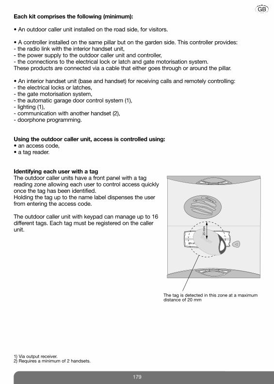
Each kit comprises the following (minimum):
• An outdoor caller unit installed on the road side, for visitors.
• A controller installed on the same pillar but on the garden side. This controller provides:- the radio link with the interior handset unit,- the power supply to the outdoor caller unit and controller,- the connections to the electrical lock or latch and gate motorisation system.These products are connected via a cable that either goes through or around the pillar.
• An interior handset unit (base and handset) for receiving calls and remotely controlling:- the electrical locks or latches,- the gate motorisation system,- the automatic garage door control system (1),- lighting (1),- communication with another handset (2),- doorphone programming.
Using the outdoor caller unit, access is controlled using:• an access code,• a tag reader.
Identifying each user with a tagThe outdoor caller units have a front panel with a tagreading zone allowing each user to control access quicklyonce the tag has been identified. Holding the tag up to the name label dispenses the userfrom entering the access code.
The outdoor caller unit with keypad can manage up to 16different tags. Each tag must be registered on the callerunit.
1) Via output receiver.2) Requires a minimum of 2 handsets.
The tag is detected in this zone at a maximumdistance of 20 mm
Mr et Mme Evêque-Mourroux
25
mm
179
GB

2.1.1 Outdoor caller units with armoured cover
2.1.2 Controller
2.2.1 Base
Handset base
Power pack
Base connection jackTransparentremovable cover
Loudspeaker
Call button (1 or 2 depending
on model)4 handsets max.per button
Blank label for user’s name(sheet of labelssupplied)Tag reading zone
Validation button
Radio link creationbutton
Slot for batteries (LR20 type, not supplied)
Radio linkcreation LED
4 captivescrews
for closing the cover
CoverController base
Fixing bracket
Connection terminal blocks
Captive screws for bracket fixing
Cable clamp (do not remove)
Grommet(remove)
Tag reading zone
Programming keypad for entering access code to allow pedestrians and carsto enter
Gate access control button
Latch/side gate accesscontrol button
180
GB
2. Description
2.2 Interior handset unit
2.1 Outdoor system
IMPORTANT: the grommets,cable clamps and screwsfor the cable clamps are inthe bag of accessories.

2.2.2 Handset unit
C
F
C
F
Cover closed Cover open
Removable belt clip
Loudspeaker
Display
Communicationbutton
Flip cover
Microphone
Cancel button
Validate button(OK)
Gate controlbutton
Inter-handsetcommunication
button
Latch/side gate controlbutton
Garage control button
(1)
Lighting control button
(1)
Up and downscroll keys
Left and rightscroll keys
Backlighting is activatedwhenever a button is pressed. It goes out again after 5 secondswhen no other button is pressed.
(1) These functions require a relay output receiver
to be installed.
181
GB
IMPORTANT: when installing the system, the handset(s) must be charged on their base before they can beused.
C
F
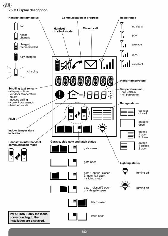
2.2.3 Display description
flat
needscharging
chargingrecommended
fully charged
charging
Scrolling text zone: - display of time- outdoor temperature- faults- access calling- current commands- handset mode
Fault
Handset in inter-handsetcommunication mode
Handset battery status
Handset in silent mode
Communication in progress
Missed callno signal
poor
average
good
excellent
Radio range
lighting off
lighting on
Lighting status
Garage, side gate and latch status
gate closed
gate open
gate 1 open/2 closed or gate half open if sliding motor
gate 1 closed/2 open or side gate open
latch closed
latch open
Garage status
Indoor temperature indication
Temperature unit:- °C: Celsius- °F: Fahrenheit
Indoor temperature
garagesclosed
garages open
garage1 open2 closed
garage 1 closed2 open
IMPORTANT: only the iconscorresponding to theinstallation are displayed.
182
GB
C
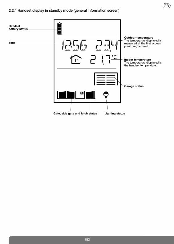
2.2.4 Handset display in standby mode (general information screen)
Handset battery status
Time
Gate, side gate and latch status Lighting status
Indoor temperatureThe temperature displayed isthe handset temperature.
Outdoor temperatureThe temperature displayed ismeasured at the first accesspoint programmed.
Garage status
183
GB

6/8 mm
3.5 mm
PZ 03 mm
PZ 26 mm
GUARANTEEThe conditions according to which the guarantee and after sales service apply are described in the generalprice list and can be sent on request. Some after sales service products and accessories, such as:• MHU01X or MHU01U power packs• LCH01X interior handset unit base• LCH02X belt clip• LCH03X handset flip cover(non-exhaustive list for indication purposes only) have a 2-year manufacturer guarantee, which cannot beextended.
184
GB
3. Tooling required
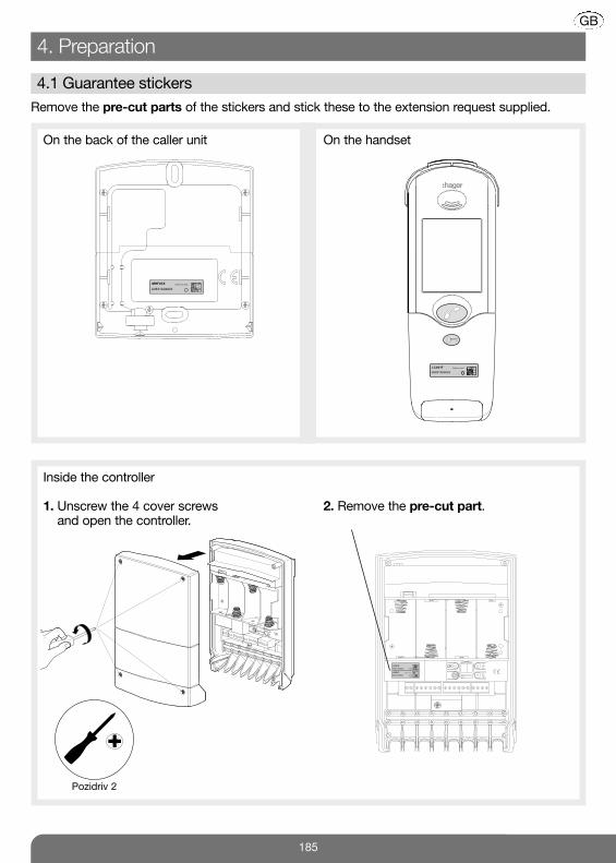
Remove the pre-cut parts of the stickers and stick these to the extension request supplied.
Inside the controller
Coller sur certif
LCB01F
A0831A04823
LCB01F
A0831A04823
On the back of the caller unit
MHF01X
A0831A04823
Coller sur certif
On the handset
LCA01F
A0831A04823
Coller sur certif
1. Unscrew the 4 cover screws and open the controller.
2. Remove the pre-cut part.
Pozidriv 2
185
GB
4. Preparation
4.1 Guarantee stickers

3. Rotate the back of the base until it is in “table” position.
4. Thread the power pack jack through thehole.
5. Connect the jack to the base making surethat the cable is positioned in thedesignated slot.
Thread the cablethrough here
Alternative cablepassage
IMPORTANT: when installing the system, the handset(s) must be charged on the base before it/they can beused.
IMPORTANT: only MHU01X or MHU01U powerpacks supplied must be used.
186
GB
4.2 Charging the handset before installation
1. Open the base.
�
2. Remove the 4 anti-slip pads.
�

6. Thread the power cable into one of theguides at the back of the base.
7. Unscrew the locking screw.
Alternative guides
Pozidriv 0
Pozidriv 0
8. Screw it back into the same place hencelocking the base in “table” position.
9. Close the base.
Pozidriv 2
10. Tighten the locking screw to prevent thebase from being opened by mistake.
11. Stick the 4 anti-slip pads to the back of the base and then put it on the table.
187
GB

12. Connect the power pack to the mains(220 V).
13. Put the handset on the base.
Electrical shockhazard
TIP: to make it easier to pick the handset up, the removable transparent cover can be removed.
The handset displaysthis message for 2 sec.:
Then IN CHARGE if thebattery is not sufficientlycharged.
If thebattery issufficientlycharged.
You can now move on to the next chapter describing how to install the doorphone.
�
�
IMPORTANT: the mains socket must remainaccessible so that the power pack can be easilydisconnected.
or
188
GB

IMPORTANT: to ensure the outdoor caller unit remains watertight, never try to open it!
1. To ensure easy use, fix the unit at a heightof 1.20 m.
2. Mark and drill the outdoor caller unit holeswith a Ø 6 mm drill bit. Also mark theplace where the cable feed hole has to bedrilled (Ø 8 mm min. recommended).
1.20 m
Please refer to the next chapter for mounting outdoor caller units with armoured cover.
Follow steps 3 to 6 below for units without armoured cover.
3. If the cable goes around the pillar, pierceone of the cable knock-outs with a cutter.
4. Push the screw covers out using a flatscrewdriver.
5. Thread the cable through thehole knocked out in step 3and screw the caller unit in place. Put the screwcovers back.
6. Use a pencil orpermanent marker to write the names.Stick a transparentprotection label ontop.
Pozidriv 2
3.5
TIP: you can print thelabels using thesoftware (EtikPrint)available on the Hagerweb site.
189
GB
5. Installing the outdoor system
5.1 Installing the outdoor caller unit

190
GB
Mounting the outdoor caller units with armoured cover232.4 mm
145 mm 145 mm
160.4 mm
145 mm 145 mm
1
2
IMPORTANT: use the label supplied and carefullyposition it in the space provided.
TIP: you canprint the labels usingthe software(EtikPrint)available on the Hagerweb site.

191
GB
4
Pozidriv 2
6
3
5

192
GB
7
8 9
3.5

193
GB
1110
12
IMPORTANT: when the armoured cover ispositioned on the unit, there should be a 1 mmclearance (use the shim for this purpose)between the pillar and armoured cover.
Pozidriv 2

1. Unscrew the locking screw from thebracket and then remove it.
2. Following the installation rules below,mark 3 fixing points and drill a hole in the pillar using a Ø 6 mm drill bit.
4 cm minimum
Outdoor caller unitcable feed
Pozidriv 2
Installation rules
To make it easier to hook the base on to the bracket choose a flat surface (or make the surface asflat as possible) on the garden side of the pillar. This is especially important for the top part of thebracket.
To guarantee an excellent radio range:• keep the space clear around the controller,• remove any dense vegetation nearby andmake sure the area is always clear,• place the controller as high up as possible(80 cm min.).• make sure there are no obstacles betweenthe controller installation point and the housewhere the handset(s) is/are installed.
Never run a cable over the top of thecontroller (especially the cable ensuringthe radio link between the outdoorcaller unit and the controller). Do notwind the cable up nearby or inside thecontroller. Instead, cut off any excesslength.
Do not place the products near metal surfaces (screens, fences, gates, etc.) or sources ofelectromagnetic disturbance:• for the controller: electricity meter, high voltage line, lighting control system, radio receiver, etc. • for the handset: hi-fi equipment, video, household appliance, electricity meter or switchboard,lighting control system, etc.• the controller must be more than 3 m away from the interior handset unit.
as highaspossible
caller unitcable
caller unitcable
outdoorcaller unit
outdoorcaller unit
194
GB
5.2 Installing the controller

3. Insert a washer and fix the bottom andthen the top of the bracket.
4. Hook the base on to the fixing bracket.
5. Lock the base in place using the lockingscrew.
Fixing with a washer
Fixing without a washer
Detach anddispose ofunused washers
Pozidriv 2
Pozidriv 2
�
�
1. To make it possible to thread the cablesthrough (for the outdoor caller unit,external power supply, motorisationsystem, etc.), remove the grommets andpierce a hole with the same diameter asthe cable using a Philips screwdriver.
2. Cut the cables to the necessary length andthen thread them through the grommets.Expose the end of the wires over a lengthof approximately 1 cm.
The cables must beentirely unwound.
195
GB
5.3 Connecting the equipment

TIP: • All terminal blocks can be unplugged to facilitate wiring.• The connections to be made are summarised on a label inside the controller cover.
3. Connecting the outdoor caller unitConnect the 4 outdoor caller unit wires to terminal blocks 15 to 18 on the controller.
4. Connecting an electrical latchConnect the latch according to the following cable cross-sections:- in 3 and 4: 0.75 mm2 up to 15 m/1.5 mm2 up to 30 m,- in 5, 6, 7 and 8: 0.22 mm2 (telephone type wire).
3.5
3.5
15 16 17 18
3 4 5 6 7 8
12 V1.5 A max.
- +
NC
-+
(( (((( ((
15/Green: Data –16/Yellow: Data +17/Red: power +18/Black: power –
Electrical latch or lockcontrol (no need forexternal power supply)
The position contact feeds back the latch status to the screen:
- latch closed (contact closed),
- latch open (contact open).
Push-button located on the garden sidefor manual latch control. Place this controldevice out of reach and sight in relation to the road (connection not compulsory).
TIP: if the cable between the outdoor caller unit and the controller hasto be lengthened, cut it at a distance of 1 m and then extend the redand black wires according to the rules below:- 0.32 mm2 min. up to 10 m,- 0.75 mm2 min. up to 15 m,- 1.5 mm2 min. up to 25 m.Extend the other wires using a telephone type cable and make theconnections via a branch box.
IMPORTANT: for the information feedback to beproperly managed, the position contact (ref. CP500 on the price list) must be wired before power-up and be in closed position when the radio link isestablished between the handset and the controller. If no contact is connected, the handset display willshow the latch is closed whatever its status.
IMPORTANT: so that the systemrecognises the latch, it must bewired before the radio link iscreated between the handset and the controller.
196
GB

5. Connecting a gate motorisation systemUse a cable cross-section of 22 mm2 (telephone type wire) to connect the system.
3.5
9 10 11 12 13 14
The position contact feeds back the gatestatus to the screen:
- gate closed (contact closed),
- gate open (contact open).
Gate motorisation control, 48 V DC/1 A dry contact relay output.The motorisation system requires an external power supply.
If a push-button allowing manualcontrol of the automatic system hasalready been installed, connectterminal blocks 12 and 14 in parallelon this manual control input.
NC
C NC NO
��
IMPORTANT: for the informationfeedback to be properly managed,the position contact (ref. CP500 onthe price list) must be wired beforepower-up and be in closed positionwhen the radio link is establishedbetween the handset and thecontroller. If no contact is connected,the handset display will show thegate is closed whatever its status.
197
GB
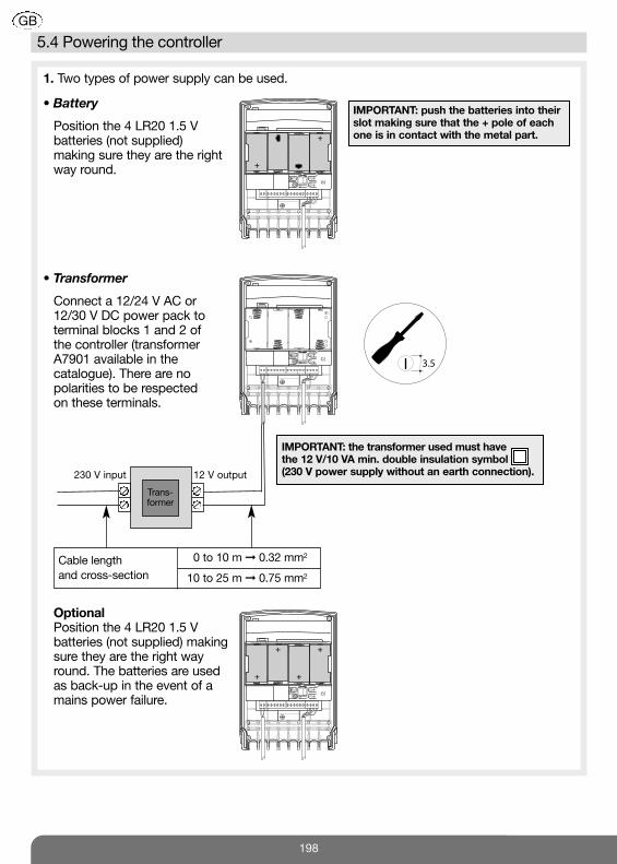
• Battery
Position the 4 LR20 1.5 V batteries (not supplied) making sure they are the right way round.
1. Two types of power supply can be used.
• Transformer
Connect a 12/24 V AC or12/30 V DC power pack toterminal blocks 1 and 2 ofthe controller (transformerA7901 available in thecatalogue). There are nopolarities to be respected on these terminals.
OptionalPosition the 4 LR20 1.5 Vbatteries (not supplied) makingsure they are the right wayround. The batteries are usedas back-up in the event of amains power failure.
3.5
+
+
+
+
IMPORTANT: push the batteries into theirslot making sure that the + pole of eachone is in contact with the metal part.
+
+
+
+
IMPORTANT: the transformer used must havethe 12 V/10 VA min. double insulation symbol (230 V power supply without an earth connection).
Trans -former
12 V output230 V input
Cable length 0 to 10 m � 0.32 mm2
and cross-section 10 to 25 m � 0.75 mm2
198
GB
5.4 Powering the controller

3. To ensure the controller is watertight, allthe grommets must be positioned andlocked into place the right way round.
4. Use the cable clamp and screwsprovided to lock the cables in place.
Do not loosen the cable clamps.
Pozidriv 2
2.When powered, the outdoor caller unit lights up and beeps every 2 sec. The radio linkcreation LED also lights up red for 2 sec. If this is not the case, check that the controller’s batteries or external power supply areproperly connected. If the radio link creation LED flashes three times every 5 seconds:- remove the controller’s power supply,- check the outdoor caller unit wiring,- reconnect the controller’s power supply.
Mr et Mme Evêque-Mourroux “BEEP”
199
GB
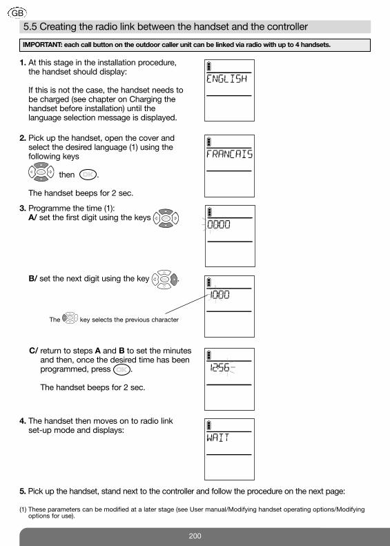
1. At this stage in the installation procedure,the handset should display:
If this is not the case, the handset needs tobe charged (see chapter on Charging thehandset before installation) until thelanguage selection message is displayed.
2. Pick up the handset, open the cover andselect the desired language (1) using thefollowing keys
then .
The handset beeps for 2 sec.
3. Programme the time (1):A/ set the first digit using the keys
B/ set the next digit using the key .
C/ return to steps A and B to set the minutesand then, once the desired time has beenprogrammed, press .
The handset beeps for 2 sec.
4. The handset then moves on to radio link set-up mode and displays:
5. Pick up the handset, stand next to the controller and follow the procedure on the next page:
The key selects the previous character
IMPORTANT: each call button on the outdoor caller unit can be linked via radio with up to 4 handsets.
200
GB
5.5 Creating the radio link between the handset and the controller
(1) These parameters can be modified at a later stage (see User manual/Modifying handset operating options/Modifyingoptions for use).

Controller Handset unit Outdoor caller unit
8. Press once on the outdoorcaller unit so that it calls the handset.
6. Put the controller in radiolink creation mode bypressing
The handset displays:
+ =
+ =
KEY 1
The radio link creation LEDlights up orange.
IMPORTANT: when using a translucent MHF01X or MHF02X outdoor caller unit and 1-button armouredcover, only the bottom key (KEY 1) can be accessed once the armoured cover has been placed on the unit.
201
GB
7. The radio link creation LEDlights up orange.

202
GB
Close the controller.
Pozidriv 2
Controller Handset unit Outdoor caller unit
The radio link LED lights upgreen for 2 sec.
The outdoor caller unit beepsfor 2 sec.
9. The handset displays:
then
C
beeps for 2 sec and
The radio link has been created.
If an error occurs,the handset displays:
It beeps 3 timesand thenautomaticallyreturns to thenext screen:
Start the radio linkcreation procedureagain.
Carry out the radio link creation procedure again for all the handsets.
Display of time, indoor and outdoortemperature, gate, side gate andlatch status (if position contactsconnected).
“BEEP”

203
Before installing the handset base, make sure the radio range between the handset and thecontroller(s) is good.
1. Stand in the place you wish to install the handset unit and quickly press the key.
2. If you have several access points: select the access point from where youwould like to listen in to background sounds using the keys
then .
C
C
3. You can hear what is happening around the outdoor caller unit at the selectedaccess point. Reception is good if at least 3 bars are displayed.If this is not the case, move the handset.
4. Press on the key and test the radiorange again for each access point.
Radio range bar graph
GB
6. Testing the radio range
IMPORTANT: if the handset units or controllers are too close to each other when you are testing the radiolink, this may generate interference (Larsen effects, crackling, etc.). Move the various devices over 3 metresaway from each other.

This chapter describes how to move the handset unit from a “table” position (in which thehandset unit is normally placed at this stage in the installation, see chapter on Charging thehandset unit before installation) to a “wall” position.
1. Remove the handset from the base. 2. IMPORTANT: the removable transparent covermust be in place when fixing the unit to thewall. If this is not the case, clip it back on.
3. Disconnect the power pack.
Electrical shockhazard
The table mounting procedure is described in the chapter on Charging the handset unit beforeinstallation.
204
GB
7. Installing the interior handset unit
7.1 On a table
7.2 On a wall

8. Rotate the back of the base until it is in wall position.
6. Unscrew the locking screw. 7. Insert the screw here and tighten it.
Pozidriv 0 Pozidriv 0
Pozidriv 2
4. Unscrew the base locking screw. 5. Open the base.
�
�
205
GB

9. Mark the 2 fixing points and then make a hole using a Ø 6 mm drill bit.
roughly 1.5 m high
10. Check the power pack jack is in theright position.
11. Thread the power cable into one of theguides at the back of the base.
Thread the cablethrough here
Alternative cablepassage
12. Fix the base to the wall usingappropriate washers and screws.
13. Close the base.
Other guidespossible
Pozidriv 2
206
GB

14. Tighten the locking screw. 15. Connect the power pack (220 V).
Pozidriv 2
16. Place the handset on the base.The handset beeps once.
C
If necessary, the icon flashes to show thehandset is being charged.
Electrical shockhazard
IMPORTANT: the mains socket must remainaccessible so that the power pack can be easilydisconnected.
207
GB

1. Press on the outdoor caller unit call button.
To confirm the call, the outdoor caller unitrings at regular intervals for 30 sec.
C
C
3. If the handset is on its base, pick it up:- if the automatic pick-up mode is activated, communication is established- otherwise, press the key.
2. If the handset is already off the base, press .
4. Open the flip cover to talk and adjust theaudio communication volume using thekeys.
5. At the end of communication, press
and/or put the handset back on the base to hang up (the handset issues 3 beeps if it is correctly placed on the base).
If no button is pressed, the communication is automatically cut off after 3 minutes.
volume +
volume –
2. The handset rings (1) (except if it is in silentmode), and the backlighting flashes.
The name of the accesspoint calling (2) is displayed.C
(1) If there is no answer, the handset rings for 20 sec. (factory setting). The duration of ringing can be adjusted (see Programming handset operating options). If the handset is on the base, it rings at the programmed volume (see Modifying handset operating options). If the handset is off the base, ringing gradually becomes louder (from level 1 to the programmed volume).
(2) Access point names can be customised (see Modifying doorphone operating options).
Perform the same test for all of the handsets.
IMPORTANTIf the handset being called is already:• communicating with anotheroutdoor caller unit or handset,
• outside the radio range, theoutdoor caller unit sounds engaged.
208
GB
8. Testing operation
8.1 Testing communication with each interior handset unit
Activate the outdoor caller unit
Status display on the handset (1)
Latch access status
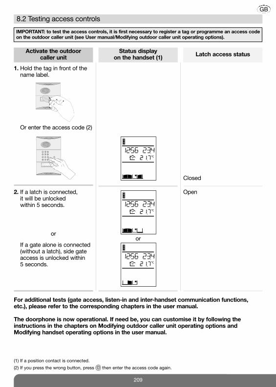
1. Hold the tag in front of thename label.
Closed
1. Or enter the access code (2)
Mr et Mme Evêque-Mourroux
C
Mr et Mme Evêque-Mourroux
2. If a latch is connected, it will be unlocked within 5 seconds.
2. If a gate alone is connected(without a latch), side gateaccess is unlocked within5 seconds.
Open
oror
C
C
(1) If a position contact is connected.
(2) If you press the wrong button, press then enter the access code again.
For additional tests (gate access, listen-in and inter-handset communication functions,etc.), please refer to the corresponding chapters in the user manual.
The doorphone is now operational. If need be, you can customise it by following theinstructions in the chapters on Modifying outdoor caller unit operating options andModifying handset operating options in the user manual.
IMPORTANT: to test the access controls, it is first necessary to register a tag or programme an access codeon the outdoor caller unit (see User manual/Modifying outdoor caller unit operating options).
209
GB
8.2 Testing access controls
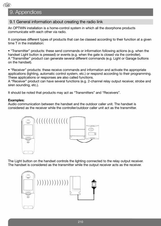
An OPTWIN installation is a home-control system in which all the doorphone productscommunicate with each other via radio.
It comprises different types of products that can be classed according to their function at a giventime T in the installation:
• “Transmitter” products: these send commands or information following actions (e.g. when thehandset Light button is pressed) or events (e.g. when the gate is closed via the controller).A “Transmitter” product can generate several different commands (e.g. Light or Garage buttonson the handset).
• “Receiver” products: these receive commands and information and activate the appropriateapplications (lighting, automatic control system, etc.) or respond according to their programming.These applications or responses are also called functions.A “Receiver” product can have several functions (e.g. 2-channel relay output receiver, strobe andsiren sounding, etc.).
It should be noted that products may act as “Transmitters” and “Receivers”.
Examples:Audio communication between the handset and the outdoor caller unit. The handset isconsidered as the receiver while the controller/outdoor caller unit act as the transmitter.
The Light button on the handset controls the lighting connected to the relay output receiver. The handset is considered as the transmitter while the output receiver acts as the receiver.
)))))))))))))
) ) ) ) ) ) ) ) ) ) ) ) )
210
GB
9. Appendices
9.1 General information about creating the radio link

211
GB
Configuring an OPTWIN installation consists in:• creating radio links between the different transmitter and receiver products to define whocontrols who and who sends information to whom.
• allocating a function to each radio link, e.g. when the Light button on the handset is pressed,this activates the lighting controlled by the output receiver for 5 minutes.
A radio link is created and a function is allocated to this radio link as part of the same procedure.This procedure is as follows:
Transmitter Receiver
1. Switch to radio link creation mode.
2. Switch to radio link creation mode.
3. Select the function.
4. Select the button or eventassociated with the function.
5. Validate the procedure.

Controller Receiver
1. Switch to radio link creation mode.
2. Switch to radio link creation mode.
3. Select the function.
9.1.1 The controller is used as a transmitter
Press on the key.
The radio link LED lights up orange.
Information available in the receiver productmanual.
Application examples
By creating a radio link between a controller and an output receiver, the following applications canbe set up:• gate opening can switch on lighting to facilitate night time access and gate closing can switchoff lighting,
• electrical latch opening can switch on courtesy lighting for a programmable duration,• etc.
• pressing on the outdoor caller unit call button can trigger a door bell installed elsewhere for aprogrammable duration.
Radio link to be created
) ) ) ) ) ) ) ) ) ) ) ) ) ) ) )
(( ((Radio link to be created
) ) ) ) ) ) ) ) ) ) ) ) ) ) ) )
212
GB

213
GB
Controller Receiver
4. Select the event associated with thefunction.
Using the , keys and controllerdisplay.
Event N° Event name Comment
1 Gate opening This event is displayed when the gate is opened
2 Gate closed This event is displayed when the gate closes,
as long as limit switches have been wired.
3 Latch opening This event is displayed when the latch is opened
4 Side gate closed This event is displayed when the side gate closes,
as long as limit switches have been wired.
5 Day breaking This event is displayed when the day breaks.
Useful for switching off night lighting.
6 Night falling This event is displayed when the night falls.
Useful for switching on night lighting.
or4. Select the key associated with thefunction.
Press: gate , latch , or call on the
outdoor caller unit.
IMPORTANT: step 5 is not necessary if the outdoorcaller unit gate, latch or call buttons have beenselected.

Controller Receiver
The radio link creation LED lights up green for 2 sec.Otherwise, start the procedure again.
The radio link has been created.
214
GB
5. Validate the procedure.
Press on the key.
IMPORTANT: if an error occurs, the radio link LED flashes red 3 times. The radio link creation process should be performed again in this case.

Handset Receiver
1. Switch to radio link creation mode.
C
C
C
Display the followingscreen using the keys
215
GB
9.1.2 The handset is used as a transmitter
Application examples
By creating a radio link between the or keys on the handset and an output receiver,
the following applications can be set up:
) ) ) ) ) ) ) ) )) ) ) ) ) ) )
) ) ) ) ) ) ) ) ) ) ) ) ) ) ) )
Radio link n° 1
Press once on the key to open the garage door and press again to close.
Radio link n° 2
Press once on the key to switch on lighting for a programmable duration.
216
GB
Handset Receiver
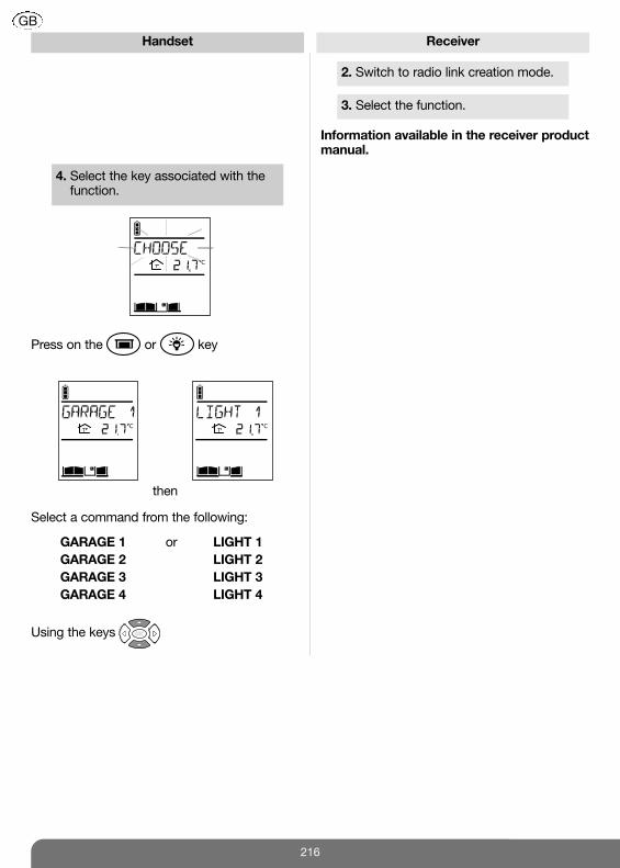
4. Select the key associated with thefunction.
C
C C
2. Switch to radio link creation mode.
3. Select the function.
Information available in the receiver productmanual.
Press on the or key
Select a command from the following:
GARAGE 1
GARAGE 2
GARAGE 3
GARAGE 4
LIGHT 1
LIGHT 2
LIGHT 3
LIGHT 4
then
or
Using the keys

217
GB
Handset Receiver
The radio link has been created.
5. Validate the procedure.
Press on the key.
The handset displays:
C
C
then
C
and
beeps for 2 sec
Garage or lighticon displayed
If an error occurs,the handset displays:
It beeps 3 times and thenautomatically returns to thegeneral informationscreen:
Perform the radiolink creationprocedure again.
C C

9.1.3 Specific cases
• Creating a radio link between a handset and several controllers or several outdoor callerunit buttonsA handset can be associated with 4 different inputs. By creating a radio link between the handsetand the controller (see chapter on Installing the doorphone), you have created radio link n° 1 (e.g. handset programmed for the 1st call button and input 1).
) )) )) )) )) ))
) ) ) ) ) ) ) ) ) ) ) ) ) ) ) ) ) ) ) ) )
) ) ) ) ) ) ) ) ) ) ) ) ) ) ) ) ) ) ) ) )
))))))
))))
))))
)))
To create radio links n° 2, n° 3, n° 4 and n° 5, follow the procedure below:
Radio link n° 2(2nd call button)
Radio link n° 1(1st call button)
Radiolink n° 3
Radiolink n° 4
Input 1
Input 2 Input 3 Input 4
Radiolink n° 5
Controller Handset Outdoor caller unit
1. Switch the controller to radio link creation modeby pressing .
The radio link creation LEDlights up orange.
218
GB
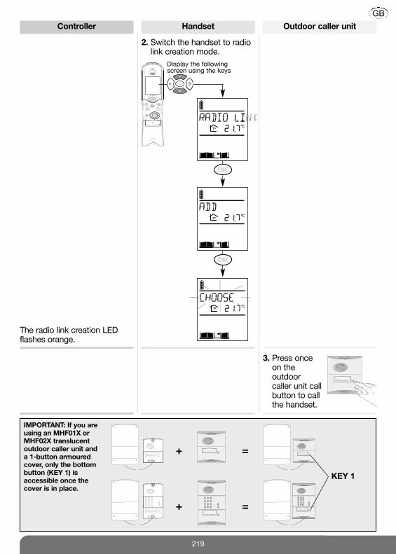
Controller Handset Outdoor caller unit
2. Switch the handset to radiolink creation mode.
3. Press onceon theoutdoor caller unit callbutton to callthe handset.
C
C
Display the followingscreen using the keys
C
+ =
+ =
KEY 1
IMPORTANT: If you areusing an MHF01X orMHF02X translucentoutdoor caller unit and a 1-button armouredcover, only the bottombutton (KEY 1) isaccessible once thecover is in place.
The radio link creation LEDflashes orange.
219
GB

Controller Handset Outdoor caller unit
The radio link creation LEDlights up green for 2 sec.
4. The handset displays:
then
and
The radio link has been created.
beeps for 2 sec.
“BEEP”
220
GB
C
C
C
If an error occurs,the handset displays:
It beeps 3 times and thenautomatically returns to the general informationscreen:
Perform the radiolink creationprocedure again.
C C

• Creating a radio link between several handsets
To allow several handsets to communicate with each other (inter-handset communication), a radiolink has to be created between each one.To do this, proceed as follows:
IMPORTANT: each handset can be linked via radio with a maximum of 7 other handsets.
C
C
C
1st handset 2nd handset
1. Switch the handset to radio link creationmode.
C
Display the followingscreen using the keys
2. Switch the handset to radio link creationmode.
C
C
Display the followingscreen using the keys
C
221
GB

1st handset 2nd handset
3. Press
4. The handset displays:
C
C
then
C
and
4. The handset displays:
C
C
then
C
and
The radio link has been created
beeps for 2 sec. beeps for 2 sec.
222
GB
If an error occurs,the handset displays:
It beeps 3 times and thenautomatically returns to the general informationscreen:
Perform the radiolink creationprocedure again.
C C

This function is used to test the radio links created between a handset and a controller.
To do this, open the controller cover and proceed as follows:
C
C
C
Handset Controller
1. Switch the handset to radio link test mode.
2. Press or .
C
Display the followingscreen using the keys
C
223
GB
9.2 Testing the radio link

Handset Controller
or .
The controller screen displays “1”.
The keyis linked viaradio to thecontroller gateoutput.
The controller screen displays “2”.
The controller screen displays “3”.
The keyis linked viaradio to thecontroller sidegate output.
The keyis linked viaradio to thecontroller latchoutput.
6. After several seconds the handset exits radiolink test mode and returns to the generalinformation screen.
3. Select the controller to be tested using the keys
4. Press again on
5. Press twice on
The controller beeps 3 times and thedisplay goes out.
224
GB

9.3.1 Deleting a radio link between a controller and a handset
This function is used to delete the radio links created between a controller and a handset.
Controller Handset Outdoor caller unit
1. Press
2. Switch the handset to radiolink deletion mode.
C
C
Display the followingscreen using the keys
C
The radio link creation LEDlights up orange.
225
GB
9.3 Deleting radio links and returning to factory programming

Controller Handset Outdoor caller unit
3. Press onceon theoutdoor callerunit callbutton to callthe handset.
C
The radio link creation LEDlights up green for 2 sec.
4. The handset displays:
C
C
then
C
beeps for 2 sec.and
The radio link has been deleted.
The outdoor caller unit beepsfor 2 sec.
“BEEP”
226
GB
The radio link creation LEDflashes orange.
If an error occurs,the handset displays:
It beeps 3 times and thenautomatically returns to the general informationscreen:
Perform the radiolink deletionprocedure again.
C C

9.3.2 Returning the handset and controller to factory programming
This procedure is used to delete all the radio links and reset all handset and controller parametersto their factory value.
1. Switch the handset to radio link deletion mode.
C
C
Display the followingscreen using the keys
C
C
227
GB

C
C
then
C
beep for 2 sec.and
2. Press and hold until the screen displays OK.
The handset displays:
3. Quickly press and then release the key.
4. Press and hold for more than 10 sec. until the radio link LED stops flashing red. The LED will then light up green for 2 sec. The outdoor caller unit beeps for 2 sec.
The handset and controller have been returned to their factory settings.
228
GB
If an error occurs,the handset displays:
It beeps 3 times and thenautomatically returns to the general informationscreen:
Perform the radiolink deletionprocedure again.
C C

When the “BATTERY ACCESS X”message appears, you have1 month in which to change thebatteries of the controllerconcerned.
C
1. Open the controller. 2. Replace the 4 flat LR20 batteries with newones.
+
+
+
+
Pozidriv 2
4. Close the controller.3.When the controller is powered, the radiolink LED lights up red for 2 sec, theoutdoor caller unit lights up and alsobeeps for 2 sec. If this is not the case,check the batteries have been correctlyinserted.
Pozidriv 2
No reprogramming is required after the batteries have been changed.
IMPORTANT: disconnect the controllerfrom the electrical network beforecarrying out any maintenance work.
Mr et Mme Evêque-Mourroux
“BEEP”
Electrical shockhazard
229
GB
10. Changing the batteries
10.1 In the main controller

1. Take the handset off its base and removethe belt clip by pressing on one of itssides.
2. Insert a flat screwdriver into the slot andpress to open the handset.
When you change the controller batteries, it is also advisable to change the handset batteries.
3. Replace the flat MTU01X battery with anew once.
4. Close the handset, put the belt clip backon and then place the handset back onits base in order to start it up.
5. Programme the time
using and . The temperature display will be updatedseveral minutes after the handset hasbeen powered.
If necessary, the icon flashes to indicate thatthe handset is charging.
3.5
C
IMPORTANT: • There is a risk of explosion if the battery/ies is/are not properly replaced.
• Replace the flat battery/ies with the same type.• Do not expose the battery to excessive heat (e.g. a flame) and do not throw it in a fire.
Dispose of flat batteries in the appropriate waste disposal containers. Li
230
GB
10.2 In the handset

231
GB
11. Questions - Answers
Plasterboard
and wood
10%
to 30%
reduction
Trees
or bushes
10%
to 30%
reduction
Brick
30%
to 50%
reduction
Concrete
and breeze-
block
50%
to 70%
reduction
Metal
and metal
cladding
70%
to 90%
reduction
Questions
Why can conversation be“broken” when using thehandset?
This can happen when you are at the radio reception limit.The controller cuts off communication when you go beyondthis limit. You should move closer to the controller.
What causes the interference(Larsen effect, crackling, etc.)that can be heard in thehandset?
This can happen when the handset is too close to anotherhandset or the controller. Move the various devices over 3 metres away from eachother.
Answers
Why does the reception qualityvary when I move around withthe handset?
If there is no electromagnetic interference or no obstaclebetween the handset and the controller, the “free field” radiorange is roughly 400 m. When the handset is inside the home,the radio range is smaller. Radio wave propagation is limited depending on the type and thickness of the walls or partitions through which they pass.
What should I do if I lose thedisplay on my handset?
What should I do if the handset
does not beep and display
when I put it back on its base?
Check the mains power supply.
Can I clean my doorphone?Use soapy water and a soft cloth to clean products whenever necessary. Do not use alcohol or acetone to clean them.
What should I do if the handsetdoes not ring during acommunication test?
• Check the radio range (see Testing the radio range) and move closer to the controller if necessary.
• Check that the handset is not in silent mode ( icon displayed).
How should I go about changingcontroller connections when ithas already been operating forseveral weeks (e.g. to connect alatch?)
Simply connect the latch or automatic control system withoutdisconnecting the power to the controller. When connecting a latch or position contact, the existingradio links must be recreated (see Appendix/Creating a radiolink between a handset and several controllers or severaloutdoor caller unit call buttons).
Simply recharge the handset on its base. The handset willcontinue to work in handsfree mode after several instants. The time must be reprogrammed (HANDSET/SETTINGS/TIME menu)

Questions
Why does the handset notdisplay the status of themotorisation system connected?
When a radio link is created between a handset and thecontroller, the position contact must be closed. If this was notthe case when the link was created, it must be deleted andrecreated (see Appendix/Deleting radio links and thenCreating a radio link between a handset and severalcontrollers or several outdoor caller unit call buttons). For a Hager brand automatic control system, check the wiringand check for any short-circuits between terminal blocks 9and 10.For an automatic control system belonging to another brand:• check that the position contact is connected to terminalblocks 9 and 10,
• when there is a position contact connected, place the gatein a position so that the position contact is closed andcheck that it is displayed on the screen.
Why does the outdoor caller unitissue 3 error beeps when a tag isheld up to it?
The tag has not been registered (see Programming doorphoneoperating functions).
Answers
Why is the “BATTERY ACCESSX” message displayed?
Change the controller batteries (see Appendix/Changing thebatteries). It is advisable to change the handset battery at thesame time.
Why is the “CHARGEHANDSET” message displayed?
Put the handset on the base to charge it.
Why is the “MEMORY FULL”message displayed when a radiolink is created?
The handset’s memory capacity has been reached. Delete some of the radio links (see Appendix/Specific cases/Creating a radio link between several handsets).
Why is communication withanother handset impossible?
Check there is a radio link between the handsets (see Appendix/Specific cases/Creating a radio link between several handsets).
What does the icondisplayed on the handset mean?
A visitor came to the outdoor caller unit while you were out. To delete the icon, press on the handset button.
How can I change the accesscode, e.g. from 4 to 6 digits?
• Delete all the programmed codes(ACCESS/CODES/DELETE menu)
• Modify the size of the access codes (ACCESS/CODES/SIZE menu)
• Reprogramme all the codes (ACCESS/CODES/ADD menu)
What should I do if I cannotoperate the latch?
Check the wiring and its characteristics (12 V, 1.5 A max.). If the latch is an addition to the initial installation, the existingradio link must be deleted and a new one created (seeAppendix/Deleting radio links and then Creating a radio linkbetween a handset and several controllers or several outdoorcaller unit call buttons).
232
GB

Waste processing of electrical and electronic devices at the end of their service life (Applicable inEuropean Union countries and other European countries with a waste collection system). Used on productsor product packaging, this symbol indicates that the product must not be thrown out with household waste.It must be taken to a waste collection point for electrical and electronic product recycling. When you make
sure that this product is disposed of in the most appropriate manner, you are helping to protect the environmentand human health. If you would like additional information concerning the recycling of this product, please contactyour town/city council, nearest waste collection centre or the shop where you bought the product.
General data
• Failsafe multi-frequency radio technology with a free field (1) range of up to 400 m, according toenvironmental and installation conditions
• High-fidelity digital sound
Outdoor caller unit data
• External boxes made of polycarbonate• Controller and outdoor caller unit degree of protection: IP54/IK08• Operating temperature from – 20°C to + 70°C• Controller power supply: 4 LR20 type 1.5 V alkaline batteries and/or 12/24 V AC or 12/30 V DCpower supply
• 3-year battery life (with 4 LR20 batteries) (2)• Wiring using 4 wires between the outdoor caller unit and the controller• Control and powering of any type of standard or low consumption (1.5 A max.) 12 V latches. • Control of safety ELV motorisation system able to operate with a 48 V DC/1 A dry contact (relayor switch)
• All controller inputs/outputs are SELV types
Internal handset unit data
• Interior boxes made of ABS• Degree of protection: IP31/IK04• Operating temperature from -5°C to +55°C• Base powered by mains supply via 220 V/6 V transformer• Rechargeable handset powered by MTU01X plug-in lithium-ion battery• Rechargeable handset battery life when off base: 15 days (3)
(1) The free field range corresponds to the maximum theoretical distance separating the controller and the handset whenthere are no obstacles in the way (e.g. wall, screen, vegetation, electromagnetic disturbance, etc.) likely to reduce therange.
(2) The battery life is calculated for household use, i.e. 2 x 10-sec communications, 7 latch commands and 6 gatecommands per day.
(3) The battery life is based on household use, i.e. 2 x 10-sec communications, 2 inter-handset communications every 10seconds and 6 commands (2 latch commands, 2 gate commands, 1 lighting command, and 1 garage door command)per day.
233
12. Technical data
GB

234

235
Hager 08.2010
804480/A
Hager SAS
132 Boulevard d’Europe
BP 78
F-67212 OBERNAI CEDEX
Tel. +333 88 49 50 50
www.hager.com


![s3-us-west-2.amazonaws.comCi… · 324 Funk^G Funk Mark B l223Sanc]piperR(MW 274-4182 Funk Mike ll205H3rvestWoodRc»iE ... 226-1677 Funk Paul S 149SignatijreWaySW 246-3305 Funk R](https://static.fdocuments.net/doc/165x107/5f9f0b6f8b971057a170c737/s3-us-west-2-ci-324-funkg-funk-mark-b-l223sancpiperrmw-274-4182-funk-mike.jpg)


