Montage-, Betriebs- und Wartungsanleitung Installation ... · Montage-, Betriebs- und...
12
Montage-, Betriebs- und Wartungsanleitung Installation, operating and maintenance instructions Refix Refix Membran-Druckausdehnungsgefäße sind Druckgeräte. Eine Membrane teilt das Gefäß in einen Wasser- und einen Gasraum mit Druckpolster. Die Konformität im Anhang bescheinigt die Übereinstimmung mit der Richtlinie 2014/68/EU. Der Umfang der Baugruppe ist der Konformitätserklärung zu entnehmen. Die gewählte technische Spezifikation zur Erfüllung der grundle- genden Sicherheitsanforderungen des Anhangs I der Richtlinie 2014/68/EU ist dem Typenschild bzw. der Konformitätserklärung zu entnehmen. Montage, Betrieb, Prüfung vor Inbetriebnahme, wiederkehrende Prüfungen nach den nationalen Vorschriften, in Deutschland nach der Betriebssicherheitsverordnung. Entsprechend sind Montage und Betrieb nach dem Stand der Technik durch Fachpersonal und speziell eingewiesenes Personal durchzuführen. Erforderliche Prüfungen vor Inbetrieb- nahme, nach wesentlichen Veränderungen der Anlage und wiederkehrende Prüfungen sind vom Betreiber ge- mäß den Anforderungen der Betriebssicherheitsverord- nung zu veranlassen. Empfohlene Prüffristen siehe Abschnitt „Prüffristen“. Es dürfen nur Refix ohne äußere, sichtbare Schäden am Druckkörper installiert und betrieben werden. Veränderungen am Refix, z. B. Schweißarbeiten oder mechanische Verformungen, sind unzulässig. Bei Austausch von Teilen sind nur die Originalteile des Herstellers zu verwenden. Parameter einhalten Angaben zum Hersteller, Baujahr, Herstellnummer sowie die technischen Daten sind dem Typenschild zu entnehmen. Es sind geeignete sicherheitstechnische Maßnahmen zu treffen, damit die angegebenen zulässigen max. und min. Betriebsparameter (Druck, Temperatur) nicht über- bzw. unterschritten werden. Eine Überschreitung des max. zul. Druck (PS) wasser- und gasseitig, sowohl im Betrieb als auch beim gasseitigen Befüllen, ist auszuschließen. Der Vordruck p 0 darf keinesfalls den max. zul. Druck (PS) überschreiten. Selbst bei Gefäßen mit max. zul. Druck größer 4 bar darf der Vordruck bei Lagerung und Transport nicht mehr als 4 bar betragen. Zur Gas- befüllung ist ein Inertgas, z. B. Stickstoff, zu verwenden. Korrosion Refix sind aus Stahl gefertigt, außen beschichtet. Ein Abnutzungszuschlag (Korrosionszuschlag) wurde nicht vorgesehen. Bei Einsatz von Refix in Syste- men mit Trink- und Nichttrinkwasser ist keine Korrosion des Behälters zu erwarten, da entweder eine Vollmembrane zum Einsatz kommt oder die Gefäße von innen beschichtet werden. Wärmeschutz In Wassererwärmungsanlagen ist bei Personengefähr- dung durch zu hohe Oberflächentemperaturen vom Be- treiber ein Warnhinweis in der Nähe des Refix anzubringen. Aufstellungsort Eine ausreichende Tragfähigkeit des Aufstellortes ist unter Beachtung der Vollfüllung des Refix mit Wasser sicherzu- stellen. Für das Entleerungswasser ist ein Ablauf bereit- zustellen, erforderlichenfalls ist eine Kaltwasserzumischung vorzusehen (siehe auch Abschnitt „Montage“). Bei der Konstruktion der Behälter sind standardmäßig keine Querbeschleunigungskräfte berücksichtigt, da spannungsfreie (momentfreie), schwingungsfreie Montage vorgeschrieben ist. Das Missachten dieser Anleitung, insbesondere der Sicherheitshinweise, kann zur Zerstörung und Defekten am Refix führen, Personen gefährden sowie die Funktion beeinträchtigen. Bei Zuwiderhandlung sind jegliche Ansprüche auf Gewährleistung und Haftung ausgeschlossen. Refix diaphragm pressure expansion vessels are pressure devices. A diaphragm separates Refix in a water and a gas space with pressure pad. The attached conformity certification certifies the compliance to the Pressure Equipment Directive 2014/68/EU. Please refer to the Declaration of Conformity for the scope of the assembly. Please refer to the typeplate or the Declaration of Conformity for the selected technical specifi- cation for the fulfilment of the basic security requirements of Annex I of the Directive 2014/68/EU. Mounting, operation, test before operation, regular check-up According to the governing local regulations, in Germany according to the Operational Safety Regulation.The installation and the operation to be performed to the art of technique by professional installers and authorised technical personnel. Necessary tests before operation, after fundamental changes in the installation and periodic inspection have to be initiated by the user acc. to the requirements of the Operational Safety Regulation. Recommendations regarding periodic check-up: compare paragraph „periodic check-up“. Only Refix without visible external damage to the pressure body may be installed and operated. Changes to the Refix for instance welding operations or mechanical deformations are impermissible. Only original parts of the manufacturer may be used when replacing parts. Observe the Parameters Details concerning manufacturer, year of manufacture, serial number and the technical data are provided on the name plate. Suitable measures must be taken so that the specified permis- sible maximum and minimum operating parameters (pressure, temperatrue) are adhered to. Exceeding the permissible ope- rating pressure of the water and the gas systems both during operation and when filling the gas system must be excluded. On no account must the gas pre-pressure exceed the max. allowable pressure. Even with vessels having a permissible operating pressure above 4 bar, the gas pre-pressure for storage and transport may not exceed 4 bar. An inert gas, for instance nitrogen, should be used for the gas charge. Corrosion Refix are made of steel and are coated on the outside. A wear allowance (corrosion allowance) was not provided for. If Refix is used in systems with potable and non-potable water no cor- rosion of the vessel is to be expectedbecause the vessels are equipped with a bladder or the vessels are coated. Thermal protection In water heating systems, a warning instruction must be provi- ded by the operator near the Refix if persons are endangered by excessive surface temperatures. Place of installation It must be ensured that the place of installation has an adequa- te load-carrying capacity, taking into account the Refix will be filled with water. A drain must be provided for the draining water and a cold water admixture facility must be provided if required (see also the section "Installation"). The standard design of the vessels does not consider the forces of lateral accelaration. Failure to heed these instructions especially the safety instruc- tions can result in the destruction of and defects on the Refix, endanger persons and impair the operation. Any claims for war- ranty and liability are excluded if these instructions are violated. Allgemeine Sicherheitshinweise General safety instructions
Transcript of Montage-, Betriebs- und Wartungsanleitung Installation ... · Montage-, Betriebs- und...
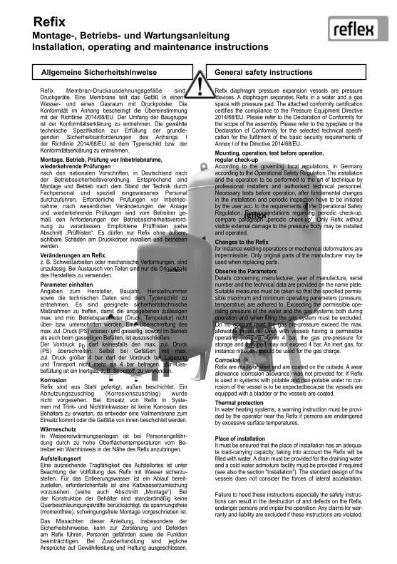
Montage-, Betriebs- und Wartungsanleitung Installation, operating and maintenance instructions
Refix
Refix Membran-Druckausdehnungsgefäße sind Druckgeräte. Eine Membrane teilt das Gefäß in einen Wasser- und einen Gasraum mit Druckpolster. Die Konformität im Anhang bescheinigt die Übereinstimmung mit der Richtlinie 2014/68/EU. Der Umfang der Baugruppe ist der Konformitätserklärung zu entnehmen. Die gewählte technische Spezifikation zur Erfüllung der grundle-genden Sicherheitsanforderungen des Anhangs I der Richtlinie 2014/68/EU ist dem Typenschild bzw. der Konformitätserklärung zu entnehmen.Montage, Betrieb, Prüfung vor Inbetriebnahme,wiederkehrende Prüfungennach den nationalen Vorschriften, in Deutschland nach der Betriebssicherheitsverordnung. Entsprechend sind Montage und Betrieb nach dem Stand der Technik durch Fachpersonal und speziell eingewiesenes Personal durchzuführen. Erforderliche Prüfungen vor Inbetrieb-nahme, nach wesentlichen Veränderungen der Anlage und wiederkehrende Prüfungen sind vom Betreiber ge- mäß den Anforderungen der Betriebssicherheitsverord- nung zu veranlassen. Empfohlene Prüffristen siehe Abschnitt „Prüffristen“. Es dürfen nur Refix ohne äußere, sichtbare Schäden am Druckkörper installiert und betrieben werden.Veränderungen am Refix, z. B. Schweißarbeiten oder mechanische Verformungen, sind unzulässig. Bei Austausch von Teilen sind nur die Originalteile des Herstellers zu verwenden.Parameter einhaltenAngaben zum Hersteller, Baujahr, Herstellnummer sowie die technischen Daten sind dem Typenschild zu entnehmen. Es sind geeignete sicherheitstechnische Maßnahmen zu treffen, damit die angegebenen zulässigen max. und min. Betriebsparameter (Druck, Temperatur) nicht über- bzw. unterschritten werden. Eine Überschreitung des max. zul. Druck (PS) wasser- und gasseitig, sowohl im Betrieb als auch beim gasseitigen Befüllen, ist auszuschließen. Der Vordruck p0 darf keinesfalls den max. zul. Druck (PS) überschreiten. Selbst bei Gefäßen mit max. zul. Druck größer 4 bar darf der Vordruck bei Lagerung und Transport nicht mehr als 4 bar betragen. Zur Gas- befüllung ist ein Inertgas, z. B. Stickstoff, zu verwenden.KorrosionRefix sind aus Stahl gefertigt, außen beschichtet. Ein Abnutzungszuschlag (Korrosionszuschlag) wurde nicht vorgesehen. Bei Einsatz von Refix in Syste- men mit Trink- und Nichttrinkwasser ist keine Korrosion des Behälters zu erwarten, da entweder eine Vollmembrane zum Einsatz kommt oder die Gefäße von innen beschichtet werden.WärmeschutzIn Wassererwärmungsanlagen ist bei Personengefähr- dung durch zu hohe Oberflächentemperaturen vom Be- treiber ein Warnhinweis in der Nähe des Refix anzubringen.AufstellungsortEine ausreichende Tragfähigkeit des Aufstellortes ist unter Beachtung der Vollfüllung des Refix mit Wasser sicherzu-stellen. Für das Entleerungswasser ist ein Ablauf bereit-zustellen, erforderlichenfalls ist eine Kaltwasserzumischung vorzusehen (siehe auch Abschnitt „Montage“). Bei der Konstruktion der Behälter sind standardmäßig keine Querbeschleunigungskräfte berücksichtigt, da spannungsfreie (momentfreie), schwingungsfreie Montage vorgeschrieben ist. Das Missachten dieser Anleitung, insbesondere der Sicherheitshinweise, kann zur Zerstörung und Defekten am Refix führen, Personen gefährden sowie die Funktion beeinträchtigen. Bei Zuwiderhandlung sind jegliche Ansprüche auf Gewährleistung und Haftung ausgeschlossen.
Refix diaphragm pressure expansion vessels are pressure devices. A diaphragm separates Refix in a water and a gas space with pressure pad. The attached conformity certification certifies the compliance to the Pressure Equipment Directive 2014/68/EU. Please refer to the Declaration of Conformity for the scope of the assembly. Please refer to the typeplate or the Declaration of Conformity for the selected technical specifi-cation for the fulfilment of the basic security requirements of Annex I of the Directive 2014/68/EU.Mounting, operation, test before operation, regular check-upAccording to the governing local regulations, in Germany according to the Operational Safety Regulation.The installation and the operation to be performed to the art of technique by professional installers and authorised technical personnel. Necessary tests before operation, after fundamental changes in the installation and periodic inspection have to be initiated by the user acc. to the requirements of the Operational Safety Regulation. Recommendations regarding periodic check-up: compare paragraph „periodic check-up“. Only Refix without visible external damage to the pressure body may be installed and operated.Changes to the Refix for instance welding operations or mechanical deformations are impermissible. Only original parts of the manufacturer may be used when replacing parts.Observe the ParametersDetails concerning manufacturer, year of manufacture, serial number and the technical data are provided on the name plate. Suitable measures must be taken so that the specified permis-sible maximum and minimum operating parameters (pressure, temperatrue) are adhered to. Exceeding the permissible ope-rating pressure of the water and the gas systems both during operation and when filling the gas system must be excluded. On no account must the gas pre-pressure exceed the max. allowable pressure. Even with vessels having a permissible operating pressure above 4 bar, the gas pre-pressure for storage and transport may not exceed 4 bar. An inert gas, for instance nitrogen, should be used for the gas charge.CorrosionRefix are made of steel and are coated on the outside. A wear allowance (corrosion allowance) was not provided for. If Refix is used in systems with potable and non-potable water no cor-rosion of the vessel is to be expectedbecause the vessels are equipped with a bladder or the vessels are coated.Thermal protectionIn water heating systems, a warning instruction must be provi-ded by the operator near the Refix if persons are endangered by excessive surface temperatures. Place of installationIt must be ensured that the place of installation has an adequa-te load-carrying capacity, taking into account the Refix will be filled with water. A drain must be provided for the draining water and a cold water admixture facility must be provided if required (see also the section "Installation"). The standard design of the vessels does not consider the forces of lateral accelaration.
Failure to heed these instructions especially the safety instruc-tions can result in the destruction of and defects on the Refix, endanger persons and impair the operation. Any claims for war-ranty and liability are excluded if these instructions are violated.
Allgemeine Sicherheitshinweise General safety instructions

Refix 2
Refix werden in Systemen mit Trink- und Nichttrink-wasser (Wassererwärmungsanlagen, Druckerhöhungs- anlagen, Wasserversorgungsanlagen), Feuerlösch- systemen und Fußbodenheizungen zum Volumen- ausgleich, zur Druckstoßdämpfung, zur Wasser-speicherung bzw. als Steuergefäß eingesetzt. Den genaueren Einsatzbereich entnehmen Sie bitte der Tabelle.Bei Verwendung von Glykol empfehlen wir den Einsatz von Gefäßen mit Vollmembran. Der Glykolanteil im Wasser darf zwischen 25% und 50% betragen.Bei der Dosierung von Zusätzen sind die Angaben der Hersteller bezüglich der zulässigen Dosiermengen, insbesondere auch hinsichtlich Korrosion, zu beach-ten. Refix sind für Öl ungeeignet und für Medien der Fluidgruppe 1 nach Richtlinie 2014/68/EU (z. B. für giftige Medien) nicht zugelassen. Andere als die ange-gebenen Medien auf Anfrage.
Refix are employed in systems with potable and non-potable water (water heating systems, pressure boosting systems, water supply systems), fire-fighting systems and floor heatings for volume expansion, for pressure surge damping, for water storage or as control vessels. The exact applications are shown in the table.
In systems with glycol we recommend to use vessels with membrane. The glycol content in the water can vary between 25% and 50%. When dosing additives, the instructions of the manufacturers with regard to the reliable dosing quantities, especially with regard to corrosion, must be observed. Refix are not suited for oil and are not admitted for media belonging to the fluid group 1 according to the Directive 2014/68/EU (e.g. for toxic media). Media other than those specified on request.
Einsatzbereiche Operating areas
Typ Type
DurchströmungsarmaturFlow fitting
Einsatz Use
durchströmt circulated
Blasenmembrane Bladder diaphragm
Refix DE, DE (E) nein no in Deutschland in Anlagen mit Nichttrinkwasser
in Germany for systems with non-pot. water
nein no ja yesRefix C-DE, DE Junior, DC nein no nein no nein noRefix HW nein no nein no nein noRefix DD T-Stück Rp ¾ T-piece Rp ¾
in Trinkwasser-installationen nach DIN 1988, gebaut und geprüft nach DIN 4807 T5
in potable water instal-lations acc. to DIN 1988, constructed and checked acc. to DIN 4807 T5
ja yes ja yesRefix DD mit Flowjet*
Flowjet* Rp ¾
Flowjet* Rp ¾ ja yes ja yes
Refix DT5, DT*** Duo-Anschl. 2 connections ja yes ja yes
Refix DT5, DT Flowjet** Flowjet** ja yes ja yes
* Flowjet Durchströmungsarmatur Rp ¾ mit Absperrung und Entleerung extra bestellen ** Flowjet Durchströmungsarmatur Rp 1¼ mit Absperrung und Entleerung im Lieferumfang*** Duo-Anschluß von DN 50 bis DN 100
* Please order the Flowjet Rp ¾ flow fitting with shut-off and evacuation separately. ** Flowjet Rp 1¼ flow fitting with shut-off and evacuation included in the delivery. *** 2 connections from DN 50 up to DN 100
max. zul. Temperatur: TSmax + 70 °C
min. zul. Temperatur: TSmin - 10 °C (nur bei entsprechendem Frostschutzmittelzusatz in Anlagen mit Nichttrinkwasser)
max. Dauerbetriebstemp. an der Voll-/Halbmembrane: + 70 °C
max. zul. Druck: PSmax → Typenschild min. zul. Druck: PSmin 0 bar
Vollmembrane (austauschbar) DT5 / DT 60-3000l, DE 33-5.000l, DE(E) 50-500l, HW 50 - 100l Vollmembrane (nicht austauschb.) DT5 / DT 8-33l, DE 2-33l, DD, C-DE, HW 25; Halbmembrane (nicht austauschb.) DE Junior, DC, HW 50-100l Gasraum: Inertgas (Fluidgruppe 2 nach RL 2014/68/EU)Wasserraum: Wasser, Wasser- Glykolgemisch (min. 25% und max 50% Glykol anteil. Wir empfehlen Gefäße mit Vollmembran einzu- setzen; Fluidgruppe 2 nach RL 2014/68/EU)
max. allowable temperature: TSmax + 70 °C
min. allowable temperature: TSmin - 10 °C (only when appropriate anti-freeze is added to non-potable water systems)
max. continuous operating temperature of the membrane/diaphragm: + 70 °C
max. allowable pressure: PSmax → typeplate min. allowable pressure: PSmin 0 bar
Membrane (exchangeable) DT5 / DT 60-3000l, DE 33-5.000l, DE(E) 50-500l, HW 50 - 100l Membrane (not exchangeable) DT5 / DT 8-33l, DE 2-33l, DD, C-DE, HW 25; Diaphragm (not exchangeable) DE Junior, DC, HW 50-100l Gas space: Inertgas (fluid group 2 acc. to Directive 2014/68/EU) Water space: Water,Water-/Glycol mixture (min. 25% and max 50% glycol fraction; We recommend vessels with membrane; fluid group 2 acc. to RL 2014/68/EU)
Zulässige Betriebtemperatur Permissible operating parameters

Refix3
Aufstellung in einem frostfreien Raum so, dass eine allseitige Besichtigung möglich ist, das Gasfüllventil sowie die wasserseitige Absperrung und Entleerung zugänglich und das Typenschild erkennbar bleibt.
Spannungsfreier (momentenfreier), schwin-gungsfreier Einbau des Refix erforderlich, keine zusätzlichen Belastungen durch Rohrleitungen oder Apparate zulässig.
Bauseitige AnbautenDruckschalter, Sicherheitsventil usw. dürfen nicht dau-erhaft auf die Membranaufhängung (S.6) montiert werden. Diese Armaturen können z.B. in der Leitung zwischen Refix und System montiert werden.
Wandhalterung für Refix 8-33 l erforderlich (für Refix 8-25 l als Zubehör lieferbar).
Gesicherte Absperrung und Entleerung für Wartungsarbeiten bei DT mit Flowjet Rp 1¼ inklusive, bei allen anderen Typen bauseits. Bei Refix DD ist Flowjet Rp ¾ als Zubehör lieferbar.
Einbaulage2-33 l waagerecht oder senkrecht, waagerechte Montage mit spezieller Konsole, senkrechte Montage mit Konsole und Spannband (33 l mit Befestigungslaschen)ab 50 l senkrecht auf vorhandenen Füßen stehendHW waagerecht
Install in a frost-free room so that inspection is possi-ble from all sides, the gas filling valve and the water shut-off and drain are accessible and the name plate remains visible.
Stress-free installation of the Refix is required, no additional loads due to pipelines or equipment!
Installation on sitePressure switch, safety valve, etc. may not be moun-ted permanently on diaphragm suspention nut (p.6).These accessories could be installed in the piping work between Refix vessel and the system for exa-mple.
Wall bracket for Refix 8 - 33 l required (for Refix 8-25l available as accessory).
Secured shut-off and drainage for maintenance operations included with DT and Flowjet Rp 1¼, with all other types to be furnished on site. For Refix DD, Flowjet Rp ¾ is available as an accessory.
Installation position2 - 33 l horizontal or vertical, horizontal installation with special bracket, vertical installation with bracket and clamping strap (33 l with fixing attachment)from 50 l vertical, standing on legs provided
HW horizontal
Allgemeine Montagehinweise General installation instructions
Refix DD sind durchströmt. Zur fachgerechten Montage empfehlen wir die Kombination mit unserer Flowjet Durchströmungsarmatur mit gesicherter Absperrung und Entleerung (→ extra Montageanleitung Flowjet).
Refix DD 8-33 l sind mit einem High-Flow-Durchströmungsstern ausgerüstet, der die ausrei-chende Durchströmung garantiert. Das beiliegende T-Stück Rp ¾ wird, entweder direkt oder in Kombination mit unserem Flowjet, so eingedichtet, dass der Durchströmungsstern bzw. die Lanze des Flowjet in die Strömung hineinragt. Das T-Stück G ¾ ist ausreichend bis zu einem Volumendurchsatz von 2,5 m³/h.
Refix DD are of the circulated type. For the proper installation, we recommend the combination with our Flowjet flow fitting with secured shut-off and evacuati-on (→ separate Flowjet assembly instructions).
Refix DD 8-33 l are equipped with a high-flow circula-tion star which guarantees the adequate circulation of the Refix. The included Rp ¾ T-piece is, either directly or in combination with our Flowjet, sealed in such a manner that the high-flow circulation star or the lance
of the Flowjet projects into the flow. The T-piece G ¾ is sufficient up to a flow rate of 2.5 m³/h.
Montage Refix DD Installation Refix DD
Flowjet Rp ¾optional

Refix 4
Diese Gefäße sind durchströmt und besitzen zwei Anschlüsse. Die erforderliche Absperr- und Entleerungsarmatur ist bauseits beizustellen. Wir empfehlen den Einsatz für folgende
max. Volumendurchsätze:DN 50 ≤ 15 m³/hDN 65 ≤ 27 m³/hDN 80 ≤ 36 m³/hDN 100 ≤ 56 m³/h
These vessels are of the circulated type and equipped with two connections. The required shut-off and drain fitting must be provided by the customer. We recom-mend the use of the following
maximum flow rates:DN 50 ≤ 15 m³/hDN 65 ≤ 27 m³/hDN 80 ≤ 36 m³/hDN 100 ≤ 56 m³/h
Montage Refix DT5, DT Installation Refix DT5, DT
Refix DE, DE(E), DE Junior, DC und HW besit-zen nur einen Anschluss und sind nicht durch-strömt. Die Absperr- und Entleerungsarmatur ist bauseits beizustellen.
Refix DE, DE(E), DE Junior DC and HW only have one connection and are not circulated. The shut-off and drain fitting must be provided by the customer.
Montage Refix DE, DE(E), DE Junior, DC, C-DE und HW
Installation Refix DE, DE(E), DE Junior DC, C-DE and HW
Refix DT (bis 500 l) werden standardmäßig mit einer Flowjet Durchströmungsarmatur Rp 1¼ ausgeliefert, die folgende Funktionen in sich vereint:
- gesicherte Absperrung- Entleerung- Bypass, bei Absperrung des Refix kann die Wassererwärmungsanlage weiterbetrieben werden.
Wir empfehlen den Einsatz für einen max. Volumendurchsatz von 7,2 m³/h.
Flowjet Rp 1¼ ist bauseits handfest auf den Gefäßanschluss zu schrauben. Dabei ist darauf zu achten, dass die Leitungsführung zwischen den Gefäßfüßen möglich ist. Eine Korrektur entgegen dem Uhrzeigersinn kann Undichtigkeiten nach sich ziehen! Wir empfehlen, beidseitig des Flowjet Verschraubun-gen zu installieren.
Refix DT (up to 500 l) are by default delivered with a Flowjet Rp 1¼ flow fitting, combining the follow ing functions:
- Secure shut-off- Drainage - Bypass, water heating system operation can continue when the Refix is shut off.
We recommend the use for a maximum flow rate of 7.2 m³/h.
The Flowjet Rp 1¼ is to be hand-screwed on the ves-sel connection. Please make sure that the arrange-ment of the wiring between the vessel feet is possible. A counter-clockwise adjustment may cause leakages! We recommend to install screw fittings on both sides of the Flowjet.
Montage Refix DT5, DT Installation Refix DT5, DT
Flowjet Rp 1¼

Refix5
Montage in WassererwärmungsanlagenInstallation in water heating systems
Druckminderer : Zur Sicherung eines konstanten Anfangsdruckes pa im Refix ist nach dem Wasser-zähler ein Druckminderer einzubauen.Sicherheitsventil : Der Ansprechdruck darf nicht über dem zulässigen Betriebsüberdruck des Refix liegen. Refix ist in der Regel unmittel-bar am Kaltwassereintritt ohne Absperrung zum Wassererwärmer zu installieren.Wird bei Refix DD mit Flowjet, DT5, DT, das Sicherheits-ventil in Strömungsrichtung gesehen vor der Durchströmungsarmatur eingebaut, dann sind folgende Bedingungen einzuhalten:Refix DD mit T-Stück Rp ¾:max. 200 l WassererwärmerRefix DT5, DT mit Durchströmungsarmatur Rp 1¼:max. 5000 l WassererwärmerEinbau des Refix stets am Kaltwasserzulauf zum Wassererwärmer, nicht an warmwasserführenden Rohrleitungen.
Pressure reducer : To ensure a constant starting pressure pa in the Refix, a pressure reducer must be installed after the water meter.Safety valve : The opening pressure may not be above the permissible operating pressure of the Refix. Refix should generally be installed directly at the cold water inlet without shut-off to the hot water storage tank. With Refix DD with Flowjet, DT5, DT, the safety valve may also be installed immediately in front of the flow fitting seen in the flow direction, if the following condi-tions are adhered to:Refix DD with T-piece Rp ¾ : max. 200 l hot water storage tankRefix DT5, DT flow fitting Rp 1¼:max. 5000 l hot water storage tankAlways install the Refix in the cold water supply to the hot water storage tank, not in pipelines carrying hot water.
2
1
2
1
Refix DD mit Flowjet Refix DD with Flowjet
WW Hot water
KW Cold water
Verbraucher Consumer
Refix DD 8-33 l mit Flowjet
pa
p0
2
1
Refix DD oder DT5, DT Refix DD or DT5, DT
WW Hot water
KW Cold water
Verbraucher Consumer
Refix DD 8-33 l ohne Flowjet
pa
p0
2
1
Refix DT5, DT 80-3000 l
Refix DT5, DT mit Flowjet Rp 1¼Refix DT5, DT with Flowjet Rp 1¼
WW Hot water
KW Cold water
Verbraucher Consumer
Refix DT5, DT 60-500 l mit Flowjet Rp 1¼
pa
2
1

Refix 6
Montage in DruckerhöhungsanlagenInstallation in pressure boosting systems
Der Einsatz kann auf der Vordruckseite, der Nach-druckseite oder beidseitig der Druckerhöhungsanlage erforderlich werden. Bei Einsatz auf der Vordruckseite besteht die Notwendigkeit, die Schaltung und die Größenbestimmung mit dem zuständigen Wasserversorgungsunternehmen abzustimmen. Beachten Sie bitte den begrenzten Volumendurchsatz in Abhängigkeit von der Anschlussnennweite (→ S. 4).
The use of the Refix may become necessary on the primary pressure side, the final pressure side or on both sides of the pressure boosting system. When used on the primary pressure side it is necessary to coordinate the circuit and the size with the responsible water supply company. Please note the limited volume throughput as a func-tion of the nominal width of the connection (→ p. 4).
(Installation nicht zugelassen im Geltungsbereich der DIN 1988)(Installation not allowed in the scope of application of the DIN 1988)
Refix DD mit Flowjet und DT5, DT Refix DD with Flowjet and DT5, DT
Druckerhöhungsanlage Pressure boosting system
Refix DD 8-33 l
mit FlowjetpE
p0
pminV pa
p0
Vers
orgu
ngsl
eitu
ng
Sup
ply
line
Refix DD oder DT5, DT Refix DD or DT5, DT
Refix DD 8-33 l
Refix DT5, DT 80-3000 l
Vers
orgu
ngsl
eitu
ng
Sup
ply
line
Vers
orgu
ngsl
eitu
ng
Sup
ply
line
pE
p0p0
pE
pminV pa
pminV pa
Druckerhöhungsanlage Pressure boosting system
Refix DE oder DC Refix DE or DC
Druckerhöhungsanlage Pressure boosting system
Refix DE 2-5000 lpE
p0
pminV pa
p0
Vers
orgu
ngsl
eitu
ng
Sup
ply
line
Gasfüllventil Gas filling valve
Wasseranschluss, Durchströmungs- richtung beidseitigWater connection,bilateral flow direction
Gasfüllventil Gas filling valve
Wasseranschluss, Durchströmungs- richtung beidseitigWater connection,bilateral flow direction
Gasfüllventil Gas filling valve
Wasseranschluss Water connectionRefix HW
Inbetriebnahme Start-up
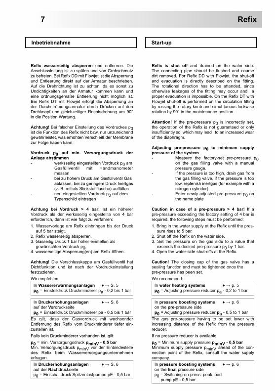
Refix wasserseitig absperren und entleeren. Die Anschlussleitung ist zu spülen und von Grobschmutz zu befreien. Bei Refix DD mit Flowjet ist die Absperrung und Entleerung direkt auf der Armatur beschrieben. Auf die Drehrichtung ist zu achten, da es sonst zu Undichtigkeiten an der Armatur kommen kann und eine ordnungsgemäße Entleerung nicht möglich ist. Bei Refix DT mit Flowjet erfolgt die Absperrung an der Durchströmungsarmatur durch Drücken auf den Drehknopf und gleichzeitiger Rechtsdrehung um 90° in die Position Wartung.
Achtung! Bei falscher Einstellung des Vordruckes p0 ist die Funktion des Refix nicht bzw. nur unzureichend gewährleistet, was erhöhten Verschleiß der Membrane zur Folge haben kann.
Vordruck p0 auf min. Versorgungsdruck der Anlage abstimmen- werksseitig eingestellten Vordruck p0 am Gasfüllventil mit Handmanometer messen- bei zu hohem Druck am Gasfüllventil Gas ablassen, bei zu geringem Druck Inertgas (z. B. mittels Stickstoffflasche) auffüllen- neu eingestellten Vordruck p0 auf dem Typenschild eintragen
Achtung bei Vordruck > 4 bar! Ist ein höherer Vordruck als der werksseitig eingestellte von 4 bar erforderlich, dann ist wie folgt zu verfahren:1. Wasservorlage am Refix einbringen bis der Druck auf 5 bar steigt,2. Refix wasserseitig absperren,3. Gasseitig Druck 1 bar höher einstellen als gewünschten Vordruck p0,4. wasserseitige Absperrung(en) am Refix öffnen.
Achtung! Die Verschlusskappe am Gasfüllventil hat Dichtfunktion und ist nach der Vordruckeinstellung festzuziehen.Wir empfehlen: In Wassererwärmungsanlagen ♦ → S. 5 p0 = Einstelldruck Druckminderer pa - 0,2 bis 1 bar
In Druckerhöhungsanlagen ♦ → S. 6 auf der Vordruckseite p0 = Einstelldruck Druckminderer pa - 0,5 bis 1 barEs gilt, dass der Gasvordruck mit wachsender Entfernung des Refix vom Druckminderer tiefer ein-zustellen ist.Falls kein Druckminderer vorhanden ist, gilt:p0 = min. Versorgungsdruck pminV - 0,5 barMin. Versorgungsdruck pminV vor der Einbindestelle des Refix beim Wasserversorgungsunternehmen erfragen. In Druckerhöhungsanlagen ♦ → S. 6 auf der Nachdruckseite p0 = Einschaltdruck Spitzenlastpumpe pE - 0,5 bar
Refix is shut off and drained on the water side. The connecting pipe should be flushed and coarse dirt removed. For Refix DD with Flowjet, the shut-off and evacuation is directly described on the fitting. The rotational direction has to be attended, since otherwise leakages of the fitting may occur and a proper evacuation is impossible. On the Refix DT with Flowjet shut-off is performed on the circulation fitting by ressing the rotary knob and simul tanous lockwise rotation by 90° in the maintenance position.
Attention! If the pre-pressure p0 is incorrectly set, the operation of the Refix is not guaranteed or only insufficiently so, which may lead to an increased wear of the diaphragm.
Adjusting pre-pressure p0 to minimum supply pressure of the system- Measure the factory-set pre-pressure p0 on the gas filling valve with a manual pressure gauge.- If the pressure is too high, drain gas from the gas filling valve, if the pressure is too low, replenish inertgas (for example with a nitrogen cylinder)- Enter newly adjusted pre-pressure p0 on the name plate
Caution in case of a pre-pressure > 4 bar! If a pre-pressure exceeding the factory setting of 4 bar is required, the following steps must be performed:1. Bring in the water supply at the Refix until the pres- sure rises to 5 bar. 2. Shut off the Refix on the water side. 3. Set the pressure on the gas side to a value that exceeds the desired pre-pressure p0 by 1 bar. 4. Open the water-side shut-offs at the Refix.
Caution! The closing cap of the gas valve has a sealing function and must be tightened once the pre-pressure has been set.We recommend: In water heating systems ♦ → p. 5 p0 = Adjusting pressure reducer pa - 0,2 to 1 bar
In pressure boosting systems ♦ → p. 6 on the pre-pressure side p0 = Adjusting pressure reducer pa - 0,5 to 1 barThe gas pre-pressure having to be set lower with increasing distance of the Refix from the pressure reducer.If no pressure reducer is available:p0 = Minimum supply pressure pminV - 0,5 barMinimum supply pressure pminV ahead of the con-nection point of the Refix, consult the water supply company. In pressure boosting systems ♦ → p. 6 on the final pressure side p0 = Switching-on press. peak load pump pE - 0,5 bar
Refix7

Refix 8
Refix ist jetzt betriebsbereit. Refix is now ready for operation.
Es ist eine jährliche Wartung erforderlich.Äußere ÜberprüfungGefäßbeschädigungen (z. B. Korrosion) sichtbar?Bei Großgefäßen im Zweifelsfall Reflex-Servicedienst einschalten; bei Kleingefäßen Austausch.
MembranprüfungStickstoffventil kurz betätigen, falls Wasser entweicht: - bei Refix DT5 / DT 8-33l, DE 2-33l, DD, C-DE, DE Junior, DC, HW 25 (Vollmembrane), HW 50-100l (Halbmembrane) -> Austausch- bei Refix DT5 / DT 60-3000l, DE 33-5.000l, DE(E) 50-500l, HW 50 - 100l (Vollmembrane)
Reflex-Servicedienst einschalten und Vollmembrane austauschen.Druckeinstellung1. Refix wasserseitig über Flowjet oder bau- seitige Armatur absperren, falls der Druck im Refix > 4 bar, dann zunächst Druck am Gasventil auf 4 bar reduzieren,2. wasserseitig über Flowjet oder bausei- tige Armatur entleeren.
Annual maintenance is required.External checkVessel damage (for instance corrosion) visible?In the case of large vessels, involve service, specialists or experts when in doubt, replace smaller vessels.
Diaphragm inspectionBriefly actuate the nitrogen valve, if water escapes:- DT5 / DT 8-33l, DE 2-33l, DD, C-DE, DE Junior, DC, HW 25 (membrane), HW 50-100l diaphragm -> Change- DT5 / DT 60-3000l, DE 33-5.000l, DE(E) 50-500l, HW 50 - 100l (membrane) Call Reflex service and change membrane.Pressure setting1. Refix water side via Flowjet or shut-off on-site fitting, if the pressure in the Refix is > 4 bar, then first reduce the pressure at the gas valve to 4 bar,2. water side via Flowjet or evacuate on-site fitting.
Wartung Maintenance
Vordruck p0 Pre-pressure p0
Anfangsdruck pa Starting pressure pa
Wird der Vordruck p0 am Gasventil nach unseren Empfehlungen auf Seite 7 einge-stellt, dann ist stets die für einen verschleiß-armen Betrieb notwendige Wasservorlage gewährleistet.
Wasservorlage einbringen:In Abhängigkeit von den bauseitigen Gege-benheiten. Im Fall Refix DD mit Flowjet:Entleerung am Flowjet schließen, Flowjet vorsichtig in Richtung „Betrieb“ öffnen. Dadurch, dass der eingestellte Vordruck unter dem Wasserversorgungsdruck (pminV bzw. pa ♦ → S. 3, 4 und 7) liegt, strömt jetzt die zum Betrieb notwendige Wasservorlage ins Refix.Im Fall Refix DT5, DT:Verdrehknopf an der Durchströmungsarmatur auf Betrieb stellen.
If the pre-pressure p0 is set at the gas valve according to our recommendations on page 7, then the necessary water supply for low-wear operation is always ensured.
Bringing in water supply:Depending on the facts and conditions on site. For Refix DD with Flowjet:Close the evacuation at the Flowjet, and carefully open the Flowjet towards „ope-ration“. Since the adjusted pre-pressure is below the water supply pressure (pminV or pa ♦ → p. 3, 4 and 7), the water supply required for operation now flows into the Refix.For Refix DT5, DT:The rotary knob on the flow fitting must be set to operating.
Montage Refix Installation Refix
Im Falle des Austauschs eines Refix DD (ab Baujahr 2006) mit einer bereits bestehenden Flowjet, ist der O-Ring der Flowjet zu entfernen und durch einen O-Ring (22 mm x 2,6 mm) zu ersetzen.
In case of exchanging a Refix DD (from year of manuf-acture 2006) including a previously installed Flowjet, remove O-ring of the Flowjet and replace by an O-ring (22 mm x 2.6 mm).
Austausch Exchange

Vor der Prüfung oder Demontage des Gefäßes bzw. drucktragender Teile ist Refix drucklos zu machen.1. Refix wasserseitig über Flowjet oder bau- seitige Armatur absperren, falls der Druck im Refix > 4 bar dann zunächst Druck am Gasventil auf 4 bar reduzieren,2. wasserseitig über Flowjet oder bauseitige Armatur entleeren, 3. gasseitig am Gasventil drucklos machen.
Neubefüllung ♦ → Inbetriebnahme S. 7/8Bei Nichtbeachtung besteht die Gefahr der Zerstörung der Membrane.
Before any check-up or disassembling of the vessel as well as the parts which exposed to pressure, the Refix vessel needs to be pressure-less.1. Shut off the Refix on the water side through the Flowjet or a built-in fitting if the pressure in the Refix is > 4 bar. Then reduce the pressure at the gas valve to 4 bar. 2. Evacuate on the water side through the Flowjet or a built-in fitting. 3. Gas-side through gas valve to be press- ure-less.For re-filling vessel ♦ → start-up p. 7/8Not following instructions can result in membrane failure.
Demontage Disassembly
Vordruck p0 einstellen ♦ → Inbetriebnahme S. 7/8 Gasfüllventil und, falls vorhanden, Gasmanometer auf Dichtheit prüfen, bei Wartungsarbeiten am Gasfüllventil ist das Gefäß zusätzlich gasseitig zu entleeren.Wasservorlage einbringen ♦ → Inbetriebnahme S. 8Refix ist jetzt wieder betriebsbereit.
Setting pre-pressure p0 ♦ → start-up page 7/8Check gas-filling valve and, if available, gas pressure gauge for leaks; when carrying out maintenance work on the gas-filling valve, the vessel gas system must also be drained.Bringing in water supply♦ → start-up page 8Refix is now ready for operation again.
Die jeweiligen nationalen Vorschriften für den Betrieb von Druckgeräten sind in jedem Fall zu beachten.In Deutschland ist die Betriebssicherheitsverordnung § 15 in Verbindung mit Anh. 2, Abschnitt 4 zu beachten.
The specific governing local regulations for the operation of pressure equipment have to be consi-dered in any case.In Germany the Operational Safety Regulation § 15 with annex 2, section 4 has to be followed.
Prüfung vor Inbetriebnahme Test before operation
Eingruppierung der Refix in Diagramm 2 des Anhangs II der Richtlinie 2014/68/EU sowie empfohlene maximale Prüffristen (in Deutschland unter Berück- sichtigung der Betriebssicherheitsverordnung § 16): Gültig bei strikter Einhaltung der Refix Montage-,Be-triebs- und Wartungsanleitung und Wechselbeanspru-chung bis 20% des zulässigen Betriebsüberdruckes:äußere Prüfung: keine Forderung nach (Anh. 2, Abschnitt 4, 5.8)innere Prüfung: - Höchstfrist nach Anhang 2, Abschnitt 4, 5 und 6 bei Refix DT5 / DT 8-33l, DE 2-33l, DD, C-DE, DE Junior, DC, HW 25 (Vollmembrane), HW 50-100l (Halbmembrane); ggf. sind geeignete Ersatzmaßnahmen zu ergreifen (z. B. Wanddickenmessung und Vergleich mit konstruktiven Vorgaben; diese können beim Hersteller angefordert werden) - Höchstfrist nach Anhang 2, Abschnitt 4, 5 und 6 bei DT5 / DT 60-3000l, DE 33-5.000l, DE(E) 50-500l, HW 50 - 100l mit Vollmembrane und Dokumentation der jährlichen Wartungsarbeiten.Festigkeitsprüfung:- Höchstfrist nach Anh. 2, Abschnitt 4, 5 und 6Die tatsächlichen Fristen muss der Betreiber auf Grundlage einer sicherheitstechnischen Bewertung, unter Beachtung der realen Betriebsverhältnisse, der Erfahrung mit Betriebsweise und Beschickungsgut und unter Berücksichtigung der gültigen nationalen Vorschriften für den Betrieb von Druckgeräten festlegen.
Classification of the Refix into Chart 2 of Annex II of the Directive 2014/68/EU and recommended maximum test periods (in Germany according to the Operational Safety Regulation § 16):Valid in case of the strict observation of the Refix mounting, operating, and maintenance instructions and alternating stress up to 20% of the admissible operating excess pressure:external inspection: no requirement acc. to (annex 2, sec. 4, 5.8)internal inspection: - maximum period acc. to annex 2, sec. 4, 5 and 6 for Refix DT5 / DT 8-33l, DE 2-33l, DD, C-DE, DE Junior, DC, HW 25 (membrane), HW 50-100l (diaphragm) if required, appropriate substitute measures are to be taken (e.g. wall thickness measurement and comparison to design specifications; these can be obtained from the manufacturer) or - maximum interval according to annex 2, sec. 4, 5 and 6 for Refix DT5 / DT 60-3000l, DE 33-5.000l, DE(E) 50-500l, HW 50 - 100l with membrane and documentation of the annual maintenance works.Strength test:- max. period acc. to annex 2, sec. 4, 5 and 6 The actual intervals must be laid down by the operator on the basis of a safety evaluation, taking due account of the actual operating conditions, the experience with operation mode and operating medium and the applicable national regulations for the operation of pressure equipment.
Prüffristen Periodic check-up
Refix9

Konformitätserklärung für eine Baugruppe Declaration of conformity of an assembly
Konstruktion, Fertigung, Prüfung von Druckgeräten Design – Manufacturing – Product Verification
Angewandtes Konformitätsbewertungsverfahren nach Richtlinie für Druckgeräte 97/23/EG des Europäischen Parlaments und des Rates vom 29. Mai 1997Operative Conformity Assessment according to Pressure Equipment Directive 97/23/EC of the European Parliament and the Council of 29 May 1997
Membran-Druckausdehnungsgefäße: ’refix D’, ’DD’, DT, ’DT5 (OEM)’, ’DE’, ’DE junior’, ’HW’
universell einsetzbar in Systemen mit Trink- und Nichttrinkwasser
Diaphragm Pressure Expansion vessels: ’refix D’, ’DD’, DT, ’DT5 (OEM)’, ’DE’, ’DE junior’, ’HW’ for operation in potable and non-potable water systems
Angaben zu Behälter, Seriennummer, Typ und Betriebsgrenzen Data about vessel, serial no., type and working limits
gemäß Typenschild according to the name plate
Beschickungsgut Operating medium
Wasser / Inertgas gemäß Typenschild Water / Inertgas according to the name plate
Normen, Regelwerk
Standards
Druckgeräterichtlinie, prEN 13831:2000 gemäß Typenschild Pressure Equipment Directive, prEN 13831:2000 according to the name plate
Druckgerät
Pressure equipment
Baugruppe nach Richtlinie 97/23/EG Artikel 3 Abs. 2.2 bestehend aus: Behälter, Membrane, Ventil und Manometer (soweit vorhanden)assembly acc. to Directive 97/23/EC article 3 para-graph 2.2 consisting of: vessel, diaphragm, valve and manometer (as available)
Fluidgruppe Fluid group 2
Konformitätsbewertungsverfahren nach Modul Conformity assessment acc. to module B + D ’refix D, DD, DT5, DT5 (OEM),
DE, DE junior, HW’Kennzeichnung gem. Richtlinie 97/23/EG Label acc. to Directive 97/23/EC CE 0045
Zertifikat-Nr. der EG-Baumusterprüfung Certificate No. of EC Type Approval
siehe Anhang 2 see annex 2
Zertifikat-Nr. der Bewertung des QS-Systems (Modul D) Certificate No. of certification of QS-System (module D) 07 202 1403 Z 0836/9/D0045
Benannte Stelle für Bewertung des QS-Systems Notified Body for certification of QS-System
TÜV Nord Systems GmbH + Co. KG Große Bahnstraße 31, 22525 Hamburg
Registrier-Nr. der Benannten Stelle Registration No. of the Notified Body 0045
Hersteller: Manufacturer:
Reflex Winkelmann GmbH Gersteinstraße 19 59227 Ahlen - Germany Telefon: +49 2382 7069 -0 Telefax: +49 2382 7069 -588 Email: [email protected]
Der Hersteller erklärt, daß die Baugruppe die Anforderungen der Richtlinie 97/23/EG erfüllt. The manufacturer herewith certifies this assembly is in conformity with directive 97/23/EC.
Manfred Nussbaumer Volker MauelMitglieder der Geschäftsführung / Members of the Management
Refix Anhang 1 Annex 1
Konformitätserklärung für ein Druckgerät (einen Behälter / eine Baugruppe) Konstruktion, Fertigung, Prüfung von DruckgerätenDeclaration of conformity of a pressure equipment (a vessel / an assembly) Design – Manufacturing – Product Verification
Angewandtes Konformitätsbewertungsverfahren nach Richtlinie für Druckgeräte2014/68/EU des Europäischen Parlaments und des Rates vom 15. Mai 2014Applied Conformity Assessment according to Pressure Equipment Directive2014/68/EU of the European Parliament and the Council of 15 May 2014
DruckausdehnungsgefäßeRefix DD, DT5, DT, DE, DE (E), C-DE, DE Junior, DC, HW
universell einsetzbar in Systemen mit Trink- und Nichttrinkwasser
Pressure expansion vesselsRefix DD, DT5, DT, DE, DE (E), C-DE, DE Junior, DC, HW
universally applicable in potable and non-potable water systems
Typ / type gemäß Typenschild Behälteraccording to name plate of vessel
Serien-Nr. / Serial no. gemäß Typenschild Behälteraccording to name plate of vessel
Herstellungsjahr / Year of manufacture gemäß Typenschild Behälteraccording to name plate of vessel
max. zulässiger Druck (PS) / max. allowable pressure (PS) gemäß Typenschild Behälteraccording to name plate of vessel
Prüfdruck (PT) / Test pressure (PT) gemäß Typenschild Behälteraccording to name plate of vessel
min. / max. zulässige Temperatur (TS)min. / max. allowable temperature (TS)
gemäß Typenschild Behälteraccording to name plate of vessel
max. Dauerbetriebstemperatur Voll- / Halbmembrane max. continious operating temperature membrane / diaphragm
gemäß Typenschild Behälteraccording to name plate of vessel
BeschickungsgutOperating medium
Wasser / trockene LuftWater / dry air
Normen, RegelwerkStandards
Druckgeräterichtlinie, EN 13831:2007 oder AD 2000 gemäß Typenschild BehälterPressure Equipment Directive, EN 13831:2007 or AD 2000 according to name plate of vessel
Druckgerät
Pressure equipment
Refix DD, DT5 / DT < 60 ltr., C-DE, DE 10 + 16 bar mit Durchmesser ≤ 740 mm, DE (E) 50-500l 10 bar, HW,Behälter Artikel 4 Abs. (1) a) i) 2. Gedankenstrich (Anhang II Diagr. 2) mit • Ausrüstung Artikel 4 Abs. (1) d): Vollmembrane und Ventil
Refix DE Junior, DC, HW,Behälter Artikel 4 Abs. (1) a) i) 2. Gedankenstrich (Anhang II Diagr. 2) mit • Ausrüstung Artikel 4 Abs. (1) d): Halbmembrane und Ventil
Refix DT5 / DT ≥ 60 ltr., DE 10 bar 300, 400 u. 600 ltr. mit Durchmesser 750 mm, DE 16 bar 300, 400 u. 600 ltr. mit Durchmesser 750 mm, DE 10 + 16 bar mit Durchmesser ≥ 1000 mm, DE 25 bar ab 80 ltr., DE, DT5 / DT 40 bar von 80 – 180 ltr.Baugruppe Artikel 4 Abs. (2) b) bestehend aus:• Behälter Artikel 4 Abs. (1) a) i) 2. Gedankenstrich (Anhang II Diagr. 2) mit
Ausrüstung Artikel 4 Abs. (1) d): Vollmembrane und Ventil• Ausrüstung Artikel 4 Abs. (1) d): Manometer
Refix DD, DT5 / DT < 60 ltr., C-DE, DE 10 + 16 bar with diameter ≤ 740 mm, DE (E) 50-500l 10 bar, HW,Vessel article 4 paragraph (1) a) i) 2. indent (Annex II table 2) with• accessories Artikel 4 Abs. (1) d): membrane and valve
Refix DE Junior, DC, HW,Vessel article 4 paragraph (1) a) i) 2. indent (Annex II table 2) with• accessories Artikel 4 Abs. (1) d): diaphragm and valve
Refix DT5 / DT ≥ 60 ltr. DE 10 bar 300, 400 and 600 ltr. with diameter 750 mm, DE 16 bar 300, 400 and 600 ltr. with diameter 750 mm, DE 10 + 16 bar with diameter ≥ 1000 mm, DE 25 bar of 80 ltr. or more, DE, DT5 / DT 40 bar 80 – 180 ltr.Assembly article 4 paragraph (2) b) consisting of:• vessel article 4 paragraph (1) a) i) 2. indent (Annex II table 2) with
accessories Artikel 4 Abs. (1) d): membrane and valve• accessories Artikel 4 Abs. (1) d): manometer
Fluidgruppe / Fluid group 2
Konformitätsbewertung nach ModulConformity assessment acc. to module B+D Refix DD, DT5, DT, DE /DE (E), C-DE, DE junior, DC, HW
Kennzeichnung gem. Richtlinie 97/23/EGLabelling acc. to Directive 97/23/EC CE 0045
Zertifikats-Nr. der EG-BaumusterprüfungCertificate-No. of EC Type Approval
siehe Anhang 2see annex 2
Zertifikats-Nr. QS-System (Modul D)Certificate-No. QA System (module D) 07 202 9120 Z 0122/15/D001
Benannte Stelle für Bewertung des QS-SystemsNotified Body for certification of QA System
TÜV Nord Systems GmbH & Co. KGGroße Bahnstraße 31, 22525 Hamburg, Germany
Registrier-Nr. der Benannten StelleRegistration-No. of the Notified Body 0045
HerstellerManufacturer
Reflex Winkelmann GmbH Gersteinstraße 19 59227 Ahlen - Germany
Telefon: +49 2382 7069-0 Telefax: +49 2382 7069-588
E-Mail: [email protected]
Der Hersteller erklärt, dass das Druckgerät (der Behälter / die Baugruppe) die Anforderungen der Richtlinie 2014/68/EU erfüllt.The manufacturer herewith declares the pressure equipment (the vessel / the assembly) to be in conformity with directive 2014/68/EU.
Norbert Hülsmann Volker MauelMitglieder der Geschäftsführung / Members of the Management

Zertifikat-Nr. der EG-BaumusterprüfungCertificate No. of EG type approval
Typ Zertifikat-Nr.Type Certificate No.Refix DD 8 - 25 Liter 10 bar - 70 °C 04 202 1 932 01 00104
8 Liter 16 bar - 70 °C 04 202 1 450 02 000028 Liter 25 bar - 70 °C 04 202 1 450 03 00237
12 Liter 16 bar - 70 °C 04 202 1 932 01 0010833 Liter 10 bar - 70 °C 04 202 1 932 01 00100
Refix DT (OEM) 8 Liter 16 bar - 70 °C 04 202 1 450 02 0000312 Liter 16 bar - 70 °C 04 202 1 932 01 00109
18 - 25 Liter 16 bar - 70 °C 04 202 1 450 03 00241Refix DT 60 - 500 Liter 10 bar - 70 °C 04 202 1 450 05 00764
80 - 500 Liter 16 bar - 70 °C 04 202 1 450 05 00765600 - 3000 Liter 10 bar - 70 °C 04 202 1 450 05 00766600 - 3000 Liter 16 bar - 70 °C 04 202 1 450 05 00767
’refix DT5 junior’ 60 - 500 Liter 10 bar - 70 °C 04 202 1 932 01 00050 Rev. 1 A’refix DIT5’ 80 - 1000 (Ø 750) Liter 10 bar - 70 °C 04 202 1 450 02 00070 A
80 - 1000 (Ø 750) Liter 16 bar - 70 °C 04 202 1 450 02 00071 A80 - 1000 (Ø 750) Liter 25 bar - 70 °C 04 202 1 450 02 00292
1000 (Ø 1000) - 3000 Liter 10 bar - 70 °C 04 202 1 450 02 00720 A1000 (Ø 1000) - 3000 Liter 16 bar - 70 °C 04 202 1 450 02 00721 A1000 (Ø 1000) - 3000 Liter 25 bar - 70 °C 04 202 1 450 03 00951
’refix DIT5’ 80 - 180 Liter 40 bar - 70 °C 04 202 1 450 04 01837’refix DE’ 8 - 33 Liter 10 bar - 70 °C 04 202 1 450 05 00694
8 - 25 Liter 16 bar - 70 °C 04 202 1 450 05 0069550 - 500 Liter 10 bar - 70 °C 07 202 1 430 Z 0507/1/D004580 - 500 Liter 16 bar - 70 °C 04 202 1 450 05 00698
600 - 5000 Liter 10 bar - 70 °C 04 202 1 450 05 00696 600 - 5000 Liter 16 bar - 70 °C 04 202 1 450 05 00697
’refix D’ 8 - 25Liter 10 bar - 70 °C 04 202 1 932 01 00103 A8 Liter 16 bar - 70 °C 04 202 1 450 02 00001 A8 Liter 25 bar - 70 °C 04 202 1 450 03 00236 A
12 Liter 16 bar - 70 °C 04 202 1 932 01 00107 A25 Liter 16 bar - 70 °C 04 202 1 450 04 01959 A33 Liter 10 bar - 70 °C 04 202 1 932 01 00102 A33 Liter 10 bar - 70 °C 04 202 1 450 02 00020 A
’refix D’ 80 - 1000 (Ø 750) Liter 10 bar - 70 °C 04 202 1 450 02 00068 A80 - 1000 (Ø 750) Liter 16 bar - 70 °C 04 202 1 450 02 00069 A80 - 1000 (Ø 750) Liter 25 bar - 70 °C 04 202 1 450 02 00260
1000 (Ø 1000) - 3000 Liter 10 bar - 70 °C 04 202 1 450 02 00718 A1000 (Ø 1000) - 3000 Liter 16 bar - 70 °C 04 202 1 450 02 00719 A1000 (Ø 1000) - 3000 Liter 25 bar - 70 °C 04 202 1 450 03 00950
’refix D’ 80 - 180 Liter 40 bar - 70 °C 04 202 1 450 02 00242’refix DE junior’ 25 Liter 10 bar - 70 °C 04 202 1 450 04 01032
50 - 600 Liter 10 bar - 70 °C 04 202 1 932 01 00083’refix HW’ 25 Liter 10 bar - 70 °C 04 202 1 450 03 00814
50 Liter 10 bar - 70 °C 04 202 1 450 02 0032080 Liter 10 bar - 70 °C 04 202 1 450 05 00068
80 - 100 Liter 10 bar - 70 °C 04 202 1 450 05 00699
* Fuß seitlich * Legs on side
** Fuß unten ** Legs on bottom
A Auslaufmodell Discontinued model
RefixAnhang 2 Annex 2
Anhang 2 RefixAnnex 2
TypType
Zertifikat-Nr.Certificate No.
Refix DD 8 - 33 Liter8 - 12 Liter
8 Liter
10 bar - 70 °C16 bar - 70 °C25 bar - 70 °C
07 202 1 403 Z 0619/1/D0045 Rev.207 202 1 403 Z 0624/1/D0045 Rev.207 202 1 403 Z 0219/13/D0045 Rev.2
Refix DT5 (OEM) 8 - 33 Liter 10 bar - 70 °C 07 202 1 403 Z 0620/1/D0045Refix DT5 80 - 3000 Liter 25 bar - 70 °C 07 202 1 403 Z 0433/2/D0045 ARefix DT 8 - 33 Liter
60 - 500 Liter80 - 300 Liter
300 - 3000 Liter300 - 3000 Liter
80 -180 Liter
10 bar - 70 °C10 bar - 70 °C16 bar - 70 °C10 bar - 70 °C16 bar - 70 °C40 bar - 70 °C
07 202 1 403 Z 0514/13/D0045 Rev.207 202 1 403 Z 0222/14/D1045 Rev.207 202 1 403 Z 0937/14/D1045 Rev.207 202 1 403 Z 0115/15/D104507 202 1 403 Z 0117/15/D104507 202 1 403 Z 0513/13/D0045
Refix C-DE 8 - 80 Liter 10 bar - 70 °C 07 202 1 403 Z 0313/13/D0045Refix DE 8 - 40 Liter
8 - 25 Liter8 Liter
12 – 25 Liter 33 – 500 Liter80 - 300 Liter
300 - 10000 Liter300 - 5000 Liter
80 - 3000 Liter80 - 180 Liter
10 bar - 70 °C16 bar - 70 °C25 bar - 70 °C10 bar - 70 °C10 bar - 70 °C16 bar - 70 °C10 bar - 70 °C16 bar - 70 °C25 bar - 70 °C40 bar - 70 °C
07 202 1 403 Z 0618/1/D0045 Rev.207 202 1 403 Z 0224/2/D0045 Rev.207 202 1 403 Z 0470/14/D1045 Rev.207 202 1 403 Z 0101/13/D0045 Rev.207 202 1 403 Z 0221/14/D1045 Rev.107 202 1 403 Z 0933/14/D1045 Rev. 207 202 1 403 Z 0111/15/D1045 Rev. 207 202 1 403 Z 0113/2/D0045 Rev. 207 202 1 403 Z 0429/2/D004504 202 1 403 Z 0431/2/D1145
Refix DE (E) 50 – 500 Liter 10 bar - 70 °C 07 202 1 403 Z 0363/13/D0045Refix DC 25 - 600 Liter 10 bar - 70 °C 07 202 1 403 Z 0366/13/D0045 Rev.2Refix DE junior 25 Liter
50 - 600 Liter10 bar - 70 °C10 bar - 70 °C
04 202 1 450 04 01032 A07 202 1 403 Z 0615/1/D0045 A
Refix HWHalbmembrane/diaphragmVollmembrane/membrane
25 - 100 Liter25 - 100 Liter
10 bar - 70 °C10 bar - 70 °C
07 202 1 403 Z 0613/1/D0045 Rev.307 202 1 403 Z 0475/14/D1045 Rev.2
* Fuß seitlich * Fuß unten A AuslaufmodellLegs on side * Legs on bottom Discontinued model
Zertifikat-Nr. der EG-BaumusterprüfungCertificate No. of EC Type Approval

SI0
136d
e-en
Q /
08 -
17 /
Sac
h-N
r. 91
1628
7 Te
chni
sche
Änd
erun
gen
vorb
ehal
ten
/ Sub
ject
to te
chni
cal m
odifi
catio
n
Reflex Winkelmann GmbH
Gersteinstrasse 1959227 AhlenGermanyTelefon: +49 2382 7069 -0Telefax: +49 2382 7069 -588
www.reflex.de