Monotonic and Shake Table Testing of Gravity Load...
10
11 th Canadian Masonry Symposium, Toronto, Ontario, May 31- June 3, 2009 MONOTONIC AND SHAKE TABLE TESTING OF GRAVITY LOAD DESIGNED REINFORCED CONCRETE FRAMES WITH UNREINFORCED MASONRY INFILL WALLS J. Centeno 1 C.E. Ventura 2 S. Foo 3 and S. Brzev 4 1 MASc. Student, University. of British Columbia, Vancouver, BC, Canada [email protected] 2 Professor, University. of British Columbia, Vancouver, BC, Canada [email protected] 3 Risk management specialist Public Works and Government Services Canada [email protected] 4 Professor, British Columbia Institute of Technology [email protected] ABSTRACT A large number of existing buildings, particularly those constructed prior to the enforcement of ductile seismic design provisions introduced in 1970’s, were primarily designed and detailed to resist gravity loads. In addition, the presence of masonry infill walls was often ignored in the structural design since they were normally considered as architectural elements. Lessons learned from past earthquakes have shown that there is an interaction between the masonry infill with the bounding frame when subjected to moderate to strong earthquake loads. Such interaction may or may not be beneficial to the structural performance, and has been a subject of many debates because of the brittle behavior of masonry and possible undesirable effects characteristic for seismic response of this system. This paper presents the first part of an experimental testing program carried out at the University of British Columbia (UBC) in Vancouver, Canada testing the performance of 1/2 scale gravity load designed reinforced concrete frames with unreinforced concrete block masonry walls. The first part of this testing program consisted of one monotonic loading test on an infilled frame and two series of shake table tests, one on an infilled frame and one on a bare frame with the UBC Earthquake Engineering Research Facility (EERF) unidirectional shake table. KEYWORDS: existing buildings , infill, lap splices INTRODUCTION A large number of existing buildings, particularly those constructed prior to the enforcement of ductile design philosophy of 1970’s, were primarily designed and detailed to resist gravity loads. The most common deficiencies in the columns of Gravity Load Designed Reinforced Concrete (GLDRC) buildings are: a) low shear strength due to widely spaced and poorly detailed transverse reinforcement; and b) limited flexural strength and ductility often due to short and lightly confined lap splices at the base. In addition, the presence of masonry infill walls was often ignored in the structural design since they were considered as non structural elements. However, lessons learned from past earthquakes and from several tests performed have shown that those walls tend to interact with the bounding frame when the structural system is subjected
Transcript of Monotonic and Shake Table Testing of Gravity Load...
11th Canadian Masonry Symposium, Toronto, Ontario, May 31- June 3, 2009
MONOTONIC AND SHAKE TABLE TESTING OF GRAVITY LOAD DESIGNED REINFORCED CONCRETE FRAMES
WITH UNREINFORCED MASONRY INFILL WALLS
J. Centeno1 C.E. Ventura2 S. Foo3and S. Brzev4 1 MASc. Student, University. of British Columbia, Vancouver, BC, Canada [email protected]
2Professor, University. of British Columbia, Vancouver, BC, Canada [email protected] 3Risk management specialist Public Works and Government Services Canada [email protected]
4Professor, British Columbia Institute of Technology [email protected]
ABSTRACT A large number of existing buildings, particularly those constructed prior to the enforcement of ductile seismic design provisions introduced in 1970’s, were primarily designed and detailed to resist gravity loads. In addition, the presence of masonry infill walls was often ignored in the structural design since they were normally considered as architectural elements. Lessons learned from past earthquakes have shown that there is an interaction between the masonry infill with the bounding frame when subjected to moderate to strong earthquake loads. Such interaction may or may not be beneficial to the structural performance, and has been a subject of many debates because of the brittle behavior of masonry and possible undesirable effects characteristic for seismic response of this system. This paper presents the first part of an experimental testing program carried out at the University of British Columbia (UBC) in Vancouver, Canada testing the performance of 1/2 scale gravity load designed reinforced concrete frames with unreinforced concrete block masonry walls. The first part of this testing program consisted of one monotonic loading test on an infilled frame and two series of shake table tests, one on an infilled frame and one on a bare frame with the UBC Earthquake Engineering Research Facility (EERF) unidirectional shake table. KEYWORDS: existing buildings , infill, lap splices INTRODUCTION A large number of existing buildings, particularly those constructed prior to the enforcement of ductile design philosophy of 1970’s, were primarily designed and detailed to resist gravity loads. The most common deficiencies in the columns of Gravity Load Designed Reinforced Concrete (GLDRC) buildings are: a) low shear strength due to widely spaced and poorly detailed transverse reinforcement; and b) limited flexural strength and ductility often due to short and lightly confined lap splices at the base. In addition, the presence of masonry infill walls was often ignored in the structural design since they were considered as non structural elements. However, lessons learned from past earthquakes and from several tests performed have shown that those walls tend to interact with the bounding frame when the structural system is subjected
to moderate or severe earthquake ground motions and that such interaction may or may not be beneficial to the performance of the structure. The demand for upgrading strategies of these buildings has become increasingly important in the last few years, especially in light of the damage observed in recent earthquakes like those in Taiwan 1999, Turkey 1999, and Pakistan 2005. Even more, according to requirements of current building codes in several countries these structures require retrofitting in order to comply with the new provisions. BACKGROUND Common construction practice before modern seismic design codes allowed GLDRC column lap splices located above the slab in each floor or above the foundation. The lap splices were typically 20 or 24 longitudinal bar diameters in length. Shear reinforcement was in the form of closed hoops with 90-degree bends and spaced at half the depth of the frame member. As a result, the section at the base of these columns is unconfined and susceptible to shear failure or bond slip of the rebar along the splice, and occasionally failing before reaching yielding of the bars in tension [1]. Researchers have performed several tests to determine the interaction between the URM infill wall and the moment resisting frame frames infilled with concrete block masonry. For instance: Brokken and Bertero [2] performed quasi-static cyclic and monotonic load tests on 1/3-scale of the lower 3-1/2 stories of an 11 story-three bay RC frame designed for high rotational ductility. Brittle shear failure of one concrete column was observed for a specimen under cyclic loading with fully grouted reinforced concrete blocks. Mehrabi, and Shing [3] did monotonic and quasi-static cyclic testing on half scale reinforced concrete frames with light shear reinforcement but without any lap splice deficiency. The frames were infilled with solid and hollow concrete block masonry. The specimen with solid concrete block showed brittle shear failure of the columns beyond 1% drift. The first observable damage of the specimen with hollow concrete block was a diagonal sliding crack in the infill, which coincided with the maximum lateral load. As the amplitude of displacement cycles increased, large slips occurred along the bed joints. Saatcioglu et al. [4] studied the response of two half-scale GLDRC frame concrete block infill assemblies involving one benchmark specimen and a retrofitted with CFRP sheets, under quasi static cyclic loading. For the unretrofitted specimen, the mode of failure of the unretrofitted specimen showed bond slip of the lap splice. This bond slip was initiated at 1.5% drift, where vertical cracks and spalling at the base of the concrete column were observed indicating bond slip due to splitting of concrete. When the specimen reached 2% lateral drift the column ties opened up and lap splice debonded from the concrete. A significant portion of the cracked infill wall remained intact, after reaching the maximum lateral drift. EXPERIMENTAL RESEARCH PROGRAM For this research program ten half scale GLDRC frames with URM infill walls were constructed with identical material and reinforcement characteristics. Only one of these URM walls was built not to have any mortar interface resulting in one bare frame with an unattached URM infill
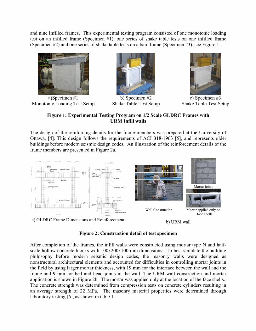
and nine Infilled frames. This experimental testing program consisted of one monotonic loading test on an infilled frame (Specimen #1), one series of shake table tests on one infilled frame (Specimen #2) and one series of shake table tests on a bare frame (Specimen #3), see Figure 1.
a)Specimen #1
Monotonic Loading Test Setup b) Specimen #2
Shake Table Test Setup c) Specimen #3
Shake Table Test Setup
Figure 1: Experimental Testing Program on 1/2 Scale GLDRC Frames with URM Infill walls
The design of the reinforcing details for the frame members was prepared at the University of Ottawa, [4]. This design follows the requirements of ACI 318-1963 [5], and represents older buildings before modern seismic design codes. An illustration of the reinforcement details of the frame members are presented in Figure 2a.
φ10mm@150mm
8φ15mm
φ6mm@125mm
2 φ15mm
See Beam Detail
25mmCover
φ6mm@125mm
840mm
1320mm
φ25mmφ15mm Hook
φ10mm@150mm
10φ25mmrebar longitudinal
φ6mm@125mm
φ 15mm
φ10mm@125mm
25mmCover Cover
25mm Beam,20mm Slab
φ 15mm
a) GLDRC Frame Dimensions and Reinforcement
Mortar joints
Wall Construction Mortar applied only on face shells
b) URM wall
Figure 2: Construction detail of test specimen
After completion of the frames, the infill walls were constructed using mortar type N and half-scale hollow concrete blocks with 100x200x100 mm dimensions. To best simulate the building philosophy before modern seismic design codes, the masonry walls were designed as nonstructural architectural elements and accounted for difficulties in controlling mortar joints in the field by using larger mortar thickness, with 19 mm for the interface between the wall and the frame and 9 mm for bed and head joints in the wall. The URM wall construction and mortar application is shown in Figure 2b. The mortar was applied only at the location of the face shells. The concrete strength was determined from compression tests on concrete cylinders resulting in an average strength of 22 MPa. The masonry material properties were determined through laboratory testing [6], as shown in table 1.
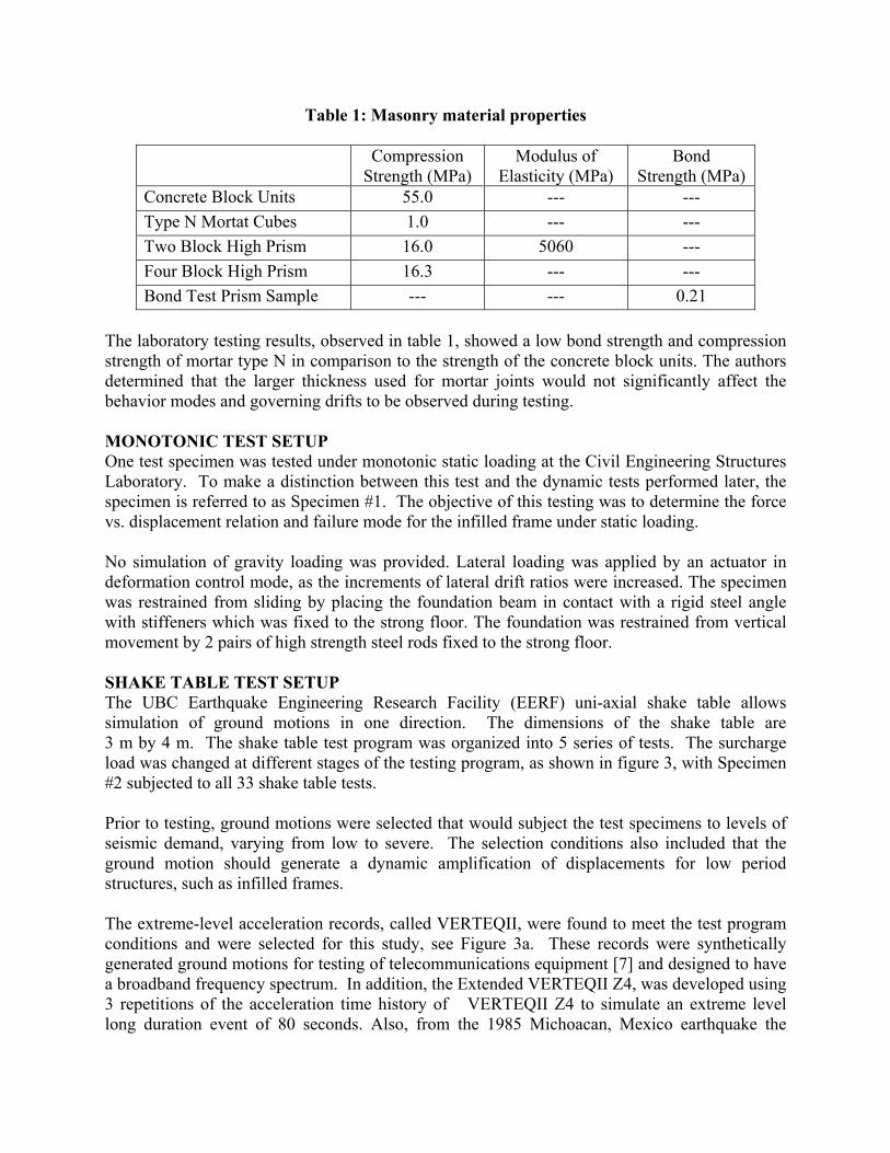
Table 1: Masonry material properties
Compression Strength (MPa)
Modulus of Elasticity (MPa)
Bond Strength (MPa)
Concrete Block Units 55.0 --- --- Type N Mortat Cubes 1.0 --- --- Two Block High Prism 16.0 5060 --- Four Block High Prism 16.3 --- --- Bond Test Prism Sample --- --- 0.21
The laboratory testing results, observed in table 1, showed a low bond strength and compression strength of mortar type N in comparison to the strength of the concrete block units. The authors determined that the larger thickness used for mortar joints would not significantly affect the behavior modes and governing drifts to be observed during testing. MONOTONIC TEST SETUP One test specimen was tested under monotonic static loading at the Civil Engineering Structures Laboratory. To make a distinction between this test and the dynamic tests performed later, the specimen is referred to as Specimen #1. The objective of this testing was to determine the force vs. displacement relation and failure mode for the infilled frame under static loading. No simulation of gravity loading was provided. Lateral loading was applied by an actuator in deformation control mode, as the increments of lateral drift ratios were increased. The specimen was restrained from sliding by placing the foundation beam in contact with a rigid steel angle with stiffeners which was fixed to the strong floor. The foundation was restrained from vertical movement by 2 pairs of high strength steel rods fixed to the strong floor. SHAKE TABLE TEST SETUP The UBC Earthquake Engineering Research Facility (EERF) uni-axial shake table allows simulation of ground motions in one direction. The dimensions of the shake table are 3 m by 4 m. The shake table test program was organized into 5 series of tests. The surcharge load was changed at different stages of the testing program, as shown in figure 3, with Specimen #2 subjected to all 33 shake table tests. Prior to testing, ground motions were selected that would subject the test specimens to levels of seismic demand, varying from low to severe. The selection conditions also included that the ground motion should generate a dynamic amplification of displacements for low period structures, such as infilled frames. The extreme-level acceleration records, called VERTEQII, were found to meet the test program conditions and were selected for this study, see Figure 3a. These records were synthetically generated ground motions for testing of telecommunications equipment [7] and designed to have a broadband frequency spectrum. In addition, the Extended VERTEQII Z4, was developed using 3 repetitions of the acceleration time history of VERTEQII Z4 to simulate an extreme level long duration event of 80 seconds. Also, from the 1985 Michoacan, Mexico earthquake the

acceleration record from station SCT1-1985 was chosen for this study, see Figure 4a. Two acceleration records were developed by modifying the time step in SCT1-1985 so as to obtain high dynamic amplification factors for the period of vibration of the test specimen (obtained from the dynamic characteristic study performed prior to shake table testing).
W1=62 kN W2=4.5 kN
W3=33 kN
a) Tests 1 - 10 b) Tests 11 - 14 c) Tests 15 - 33
Figure 3: Surcharge loads used during shake table tests
0.0
0.5
1.0
1.5
2.0
0.0 0.5 1.0 1.5 2.0
VERTEQII Z2
0 5 10 15 20 25 30 35 400.5
0.25
0
0.25
0.5
Verteq II Z2acce
lera
tion
(g)
5 10 15 20 25 30 3
NBCC 2005 Design SpectrumPS
a (g
) PS
a (g
) PS
a (g
) PS
a (g
) PS
a (g
)
0.0
0.5
1.0
1.5
2.0
0.0 0.5 1.0 1.5 2.0
VERTEQII Z4
5 400.5
0.25
0
0.25
0.5
Verteq II Z4acce
lera
tion
(g)
10 20 30 40 50 60 70 800.5
0.25
0
0.25
0.5Verteq II Z4 - Extended
acce
lera
tion
(g)
5 10 15 20 25 30 3
NBCC 2005 Design Spectrum
0.0
0.5
1.0
1.5
2.0
0.0 0.5 1.0 1.5 2.0
VERTEQIIZ4 ExtendedNBCC 2005 Design Spectrum
5 400.5
0.25
0
0.25
0.5SCT1-1985 Modified #1
acce
lera
tion
(g)
5 10 15 20 25 30 3
0.00.51.01.52.02.53.0
0.0 0.5 1.0 1.5 2.0
SCT1-1985-Modified #1NBCC 2005 Design Spectrum
5 400.5
0.25
0
0.25
0.5SCT1-1985 Modified #2
acce
lera
tion
(g)
time (sec)
0.00.51.01.52.02.53.0
0.0 0.5 1.0 1.5 2.0
SCT1-1985-Modified #2NBCC 2005 Design Spectrum
period (sec)
a) Acceleration time history of selected ground motions at 100% amplitude
b) Comparison of Acceleration Response Spectrum of selected ground motions at 100% amplitude vs NBCC 2005 Design
Spectrum for Vancouver, B.C.
Figure 4: Selected ground motions for shake table testing program

MONOTONIC TEST RESULTS The monotonic loading test showed in good detail a variation in the interaction of the infilled frame structure, presented in Figure 5 is the resulting monotonic loading vs. drift curve and in Figure 6 is the specimen at different stages of loading. The initial load resisting behavior was through diagonal compression behaviour of the masonry wall, with a high axial tension stress on the tension column, see Figure 6a. The linear elastic stiffness was constant through this behaviour with a value of 11.5 kN/mm.
Late
ral F
orce
(kN
)
0
50
100
150
200
250
0.0% 0.5% 1.0% 1.5% 2.0% 2.5% 3.0% 3.5% 4.0%
First diagonal crack in URM wall(Diagonal compression of infill)
First Mortar crack all alongsixth masonry course from t(Shear Sliding Behavior)
bed joint at he top.
Bond slip of lap in compression
KL = 11.5 kN/mm
Drift
splice observed column
Figure 5: Monotonic loading vs. drift curve
a) Diagonal Crack Patterns at
Drift 0. 77% b) Shear Sliding at
Drift 1.00% c) Bond Slip Initiates
Drift 1.65%
d) Maximum deformation reached at Drift 3.55%
e) Concrete splitting at the Tension column Drift 3.55%
f) Compression column Drift 3.55%
Figure 6:. Variation in damage for different stages of monotonic testing
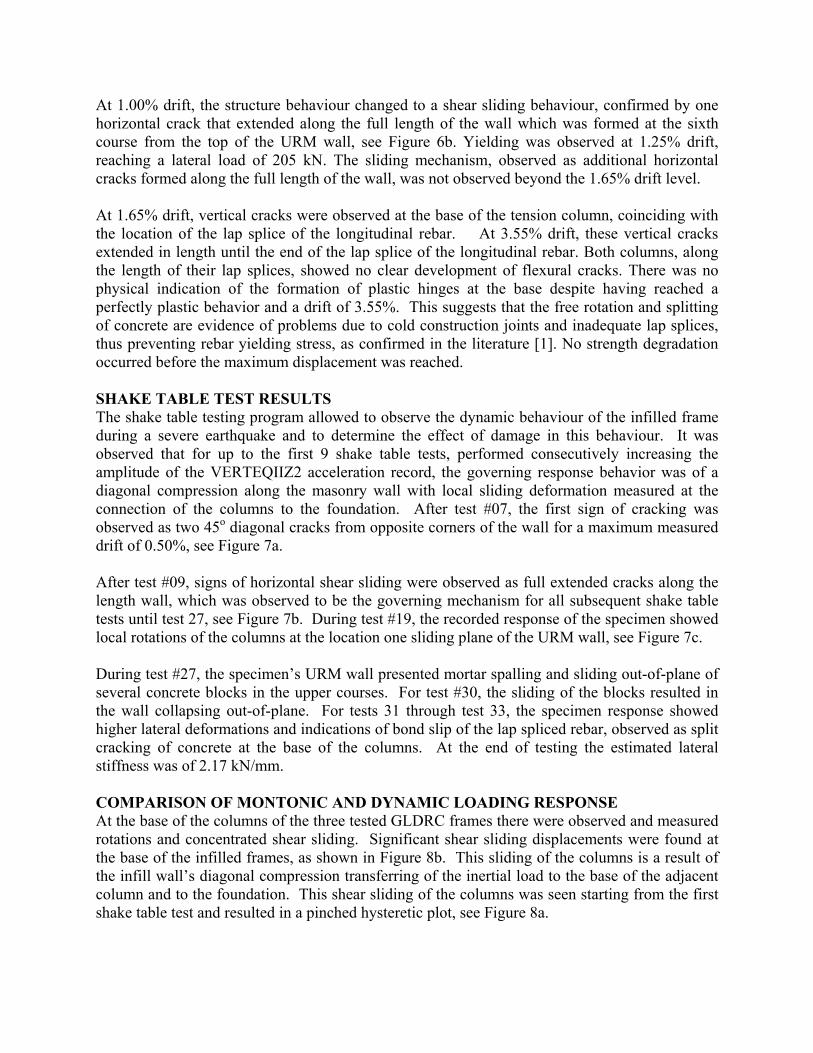
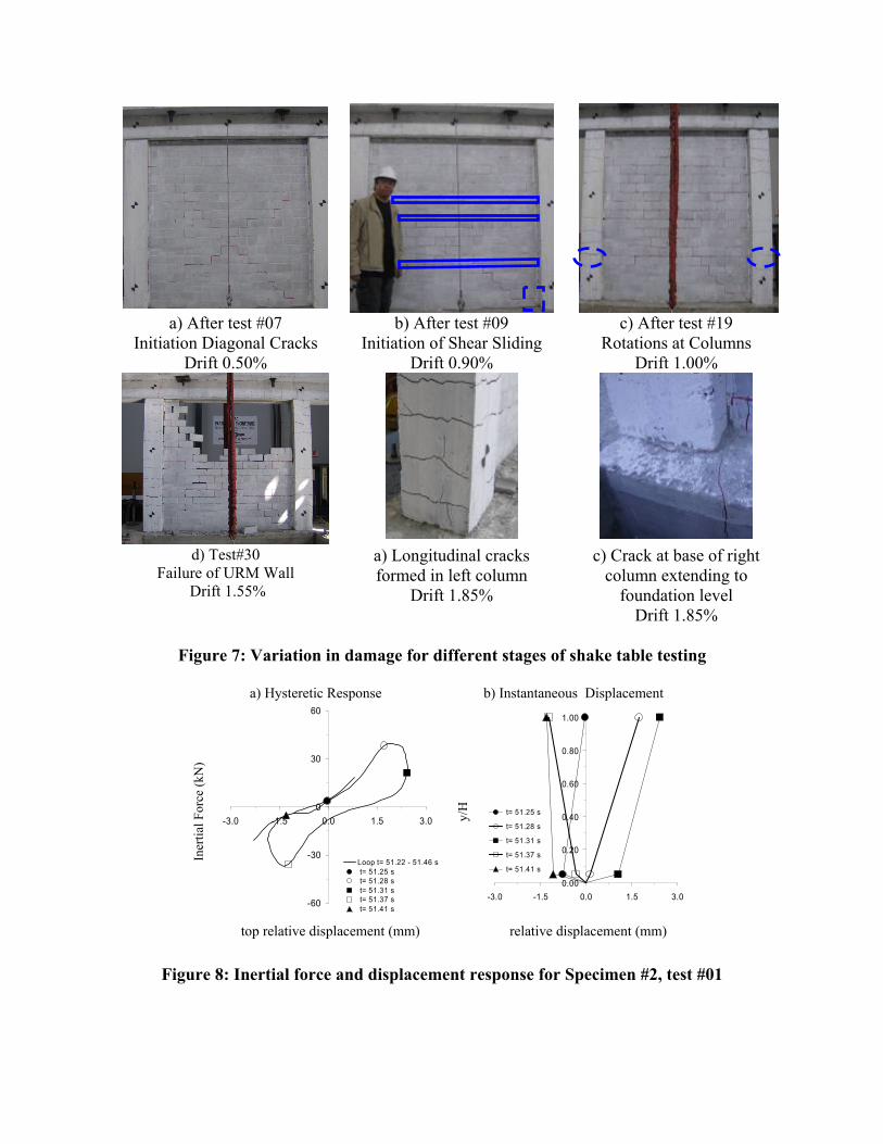
At 1.00% drift, the structure behaviour changed to a shear sliding behaviour, confirmed by one horizontal crack that extended along the full length of the wall which was formed at the sixth course from the top of the URM wall, see Figure 6b. Yielding was observed at 1.25% drift, reaching a lateral load of 205 kN. The sliding mechanism, observed as additional horizontal cracks formed along the full length of the wall, was not observed beyond the 1.65% drift level. At 1.65% drift, vertical cracks were observed at the base of the tension column, coinciding with the location of the lap splice of the longitudinal rebar. At 3.55% drift, these vertical cracks extended in length until the end of the lap splice of the longitudinal rebar. Both columns, along the length of their lap splices, showed no clear development of flexural cracks. There was no physical indication of the formation of plastic hinges at the base despite having reached a perfectly plastic behavior and a drift of 3.55%. This suggests that the free rotation and splitting of concrete are evidence of problems due to cold construction joints and inadequate lap splices, thus preventing rebar yielding stress, as confirmed in the literature [1]. No strength degradation occurred before the maximum displacement was reached. SHAKE TABLE TEST RESULTS The shake table testing program allowed to observe the dynamic behaviour of the infilled frame during a severe earthquake and to determine the effect of damage in this behaviour. It was observed that for up to the first 9 shake table tests, performed consecutively increasing the amplitude of the VERTEQIIZ2 acceleration record, the governing response behavior was of a diagonal compression along the masonry wall with local sliding deformation measured at the connection of the columns to the foundation. After test #07, the first sign of cracking was observed as two 45o diagonal cracks from opposite corners of the wall for a maximum measured drift of 0.50%, see Figure 7a. After test #09, signs of horizontal shear sliding were observed as full extended cracks along the length wall, which was observed to be the governing mechanism for all subsequent shake table tests until test 27, see Figure 7b. During test #19, the recorded response of the specimen showed local rotations of the columns at the location one sliding plane of the URM wall, see Figure 7c. During test #27, the specimen’s URM wall presented mortar spalling and sliding out-of-plane of several concrete blocks in the upper courses. For test #30, the sliding of the blocks resulted in the wall collapsing out-of-plane. For tests 31 through test 33, the specimen response showed higher lateral deformations and indications of bond slip of the lap spliced rebar, observed as split cracking of concrete at the base of the columns. At the end of testing the estimated lateral stiffness was of 2.17 kN/mm. COMPARISON OF MONTONIC AND DYNAMIC LOADING RESPONSE At the base of the columns of the three tested GLDRC frames there were observed and measured rotations and concentrated shear sliding. Significant shear sliding displacements were found at the base of the infilled frames, as shown in Figure 8b. This sliding of the columns is a result of the infill wall’s diagonal compression transferring of the inertial load to the base of the adjacent column and to the foundation. This shear sliding of the columns was seen starting from the first shake table test and resulted in a pinched hysteretic plot, see Figure 8a.
a) After test #07
Initiation Diagonal Cracks Drift 0.50%
b) After test #09 Initiation of Shear Sliding
Drift 0.90%
c) After test #19 Rotations at Columns
Drift 1.00%
d) Test#30
Failure of URM Wall Drift 1.55%
a) Longitudinal cracks formed in left column
Drift 1.85%
c) Crack at base of right column extending to
foundation level Drift 1.85%
Figure 7: Variation in damage for different stages of shake table testing
a) Hysteretic Response b) Instantaneous Displacement
Iner
tial F
orce
(kN
)
-60
-30
0
30
60
-3.0 -1.5 0.0 1.5 3.0
Loop t= 51.22 - 51.46 s t= 51.25 s t= 51.28 s t= 51.31 s t= 51.37 s t= 51.41 s
y/H
0.00
0.20
0.40
0.60
0.80
1.00
-3.0 -1.5 0.0 1.5 3.0
t= 51.25 s
t= 51.28 s
t= 51.31 s
t= 51.37 s
t= 51.41 s
top relative displacement (mm) relative displacement (mm)
Figure 8: Inertial force and displacement response for Specimen #2, test #01
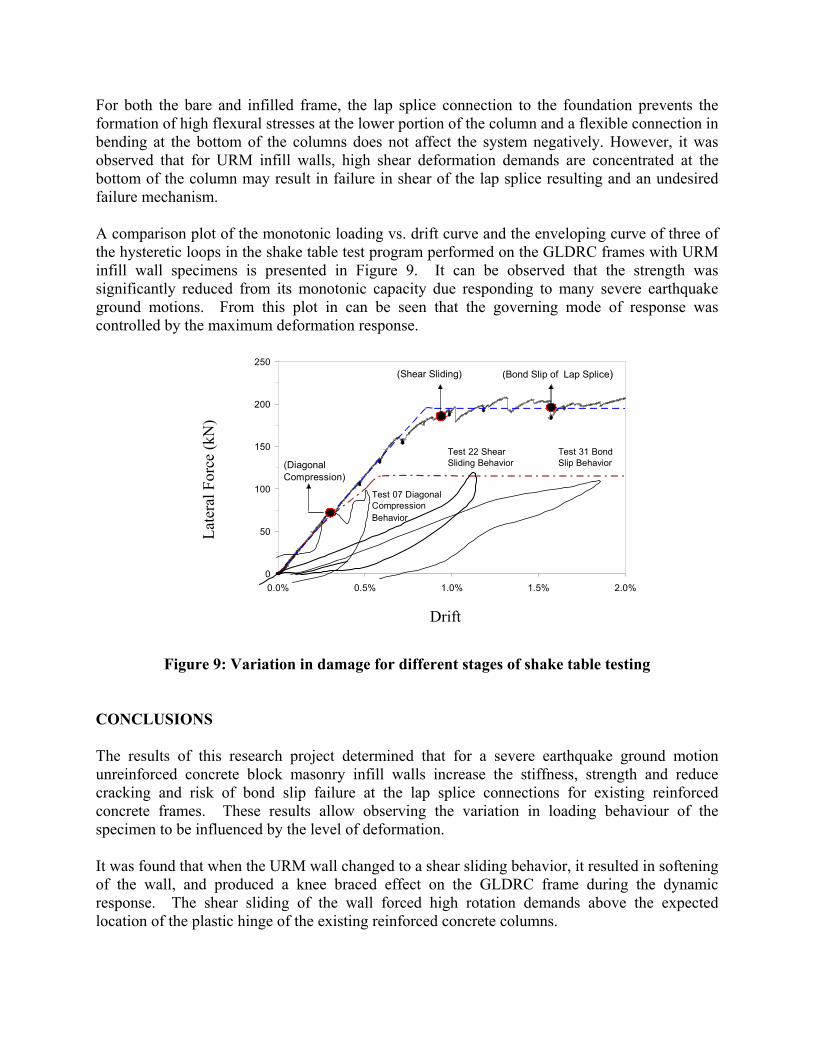
For both the bare and infilled frame, the lap splice connection to the foundation prevents the formation of high flexural stresses at the lower portion of the column and a flexible connection in bending at the bottom of the columns does not affect the system negatively. However, it was observed that for URM infill walls, high shear deformation demands are concentrated at the bottom of the column may result in failure in shear of the lap splice resulting and an undesired failure mechanism. A comparison plot of the monotonic loading vs. drift curve and the enveloping curve of three of the hysteretic loops in the shake table test program performed on the GLDRC frames with URM infill wall specimens is presented in Figure 9. It can be observed that the strength was significantly reduced from its monotonic capacity due responding to many severe earthquake ground motions. From this plot in can be seen that the governing mode of response was controlled by the maximum deformation response.
Late
ral F
orce
(kN
)
0
50
100
150
200
250
0.0% 0.5% 1.0%
Test 22 SheSliding Beha
Test 07 Diagonal Compression Behavio
1.5% 2.0%
ar vior
Test 31 Bond Slip Behavior
r
(Diagonal Compression)
(Shear Sliding) (Bond Slip of Lap Splice)
Drift
Figure 9: Variation in damage for different stages of shake table testing
CONCLUSIONS The results of this research project determined that for a severe earthquake ground motion unreinforced concrete block masonry infill walls increase the stiffness, strength and reduce cracking and risk of bond slip failure at the lap splice connections for existing reinforced concrete frames. These results allow observing the variation in loading behaviour of the specimen to be influenced by the level of deformation. It was found that when the URM wall changed to a shear sliding behavior, it resulted in softening of the wall, and produced a knee braced effect on the GLDRC frame during the dynamic response. The shear sliding of the wall forced high rotation demands above the expected location of the plastic hinge of the existing reinforced concrete columns.

The stress concentration for the base of the column during interaction with the URM wall may result in shear failure of the column connection. Existing building may be likely to present this behaviour due to resulting construction cold joint and inadequate lap splice, and could result in a catastrophic failure. This study recommends that these structures should be retrofitted to reduce sliding and strengthen in shear the connection of the columns to the slab or foundation. ACKNOWLEDGEMENTS The authors would like to acknowledge the funding support provided by Public Works and Government Services Canada. We would also like to acknowledge the contributions of the Cement Association of Canada, especially Mr. Andy Vizer; and of the Masonry Institute of British Columbia, especially Mr. Bill McEwen. REFERENCES
1. Cho, J.-Y, and Pincheira, J.A., (2006) “Inelastic Analysis of Reinforced Concrete
Columns with Short Lap Splices Subject to Reversed Cyclic Loads”, ACI Structural Journal, V. 103, No. 2, pp. 280-290.
2. Brokken S., Bertero V.V. (1983) “Studies on Effects on Infills in Seismic Resistant R/C
Construction” UCB/EERC-81/12.
3. Mehrabi A., Shing P.B., (1996) “Experimental Evaluation of Masonry-Infilled RC Frames” Journal of Structural Engineering Vol 122 No3, March,1996.
4. Saatcioglu M., Serrato F., & Foo S. (2004) “Seismic Performance Of Masonry Infill
Walls Retrofitted With CFRP Sheets” Research Report No: OCCERC 04-31, Nov. 2004, pp. 105.
5. ACI Committee 318, (1963) “Building Code Requirements for Reinforced Concrete,”
American Concrete Institute, Detroit. 6. Avendano R., (2007) “Experimental Study on Mechanical Properties of Masonry Infill
Walls” Report No 07-05 Department of Civil Engineering School of Construction and the Environment British Columbia Institute of Technology Burnaby, BC, Canada.
7. Telcordia Technologies (1995) “Network Equipment-Building Systems (NEBS)
Requirements: Physical Protection”. Telcordia Technologies Generic Requirements, GR-63-CORE, Issue 1, October 1995.
8. NRC, (2005) “National Building Code of Canada, 2005 Part 4 Structural Design”.
National Research Council of Canada. Ottawa. Canada.