Monobore CoilFlat CT Liner (Coiled Collapsed Casing) DEA...
8
Monobore CoilFlat CT Liner (Coiled Collapsed Casing) DEA-(pending) JIP Technology Demonstration The CoilFlat CT Liner is a continuous pipe-in-pipe casing, transportable on Coiled Tubing (CT) size reels, able to deliver a High Collapse MonoBore well casing system. The High Collapse capacity, higher than burst, is obtained by the steel liner sandwich wall obtained by cementing the pipe-in-pipe cavities after deployment, the pipe-in-pipe cavities being used as cementing stinger to cement the CoilFlat CT liner in the well-bore. 4- Cement is then pumped down through the pipe-in-pipe cavities to cement the liner in the wellbore and build the CoilFlat Liner sandwich wall increasing Collapse performances. 3- Additional pumping and pressurized fluid further round-up the CoilFlat Liner. 2- When the open hole section is covered, fluid is pumped down to open the CoilFlat Liner. 1- The CoilFlat Liner is lowered from the Reel, longitudinally folded, through the previously set CoilFlat Liner having the same deployed diameter
-
Upload
hoangtuyen -
Category
Documents
-
view
216 -
download
1
Transcript of Monobore CoilFlat CT Liner (Coiled Collapsed Casing) DEA...

Monobore CoilFlat CT Liner (Coiled Collapsed Casing) DEA-(pending) JIP Technology Demonstration
The CoilFlat CT Liner is a continuous pipe-in-pipe casing, transportable on Coiled Tubing (CT) size reels, able to deliver a High Collapse MonoBore well casing system.
The High Collapse capacity, higher than burst, is obtained by the steel liner sandwich wall obtained by cementing the pipe-in-pipe cavities after deployment, the pipe-in-pipe cavities being used as cementing stinger to cement the CoilFlat CT liner in the well-bore.
4- Cement is then pumped down throughthe pipe-in-pipe cavities to cement theliner in the wellbore and build theCoilFlat Liner sandwich wall increasingCollapse performances.
3- Additional pumping and pressurized fluid further round-up the CoilFlat Liner.
2- When the open hole section iscovered, fluid is pumped down toopen the CoilFlat Liner.
1- The CoilFlat Liner is lowered fromthe Reel, longitudinally folded, throughthe previously set CoilFlat Liner havingthe same deployed diameter

The CoilFlat CT Liner is a continuous pipe-in-pipe liner casing, transportable on Coiled Tubing (CT) size reel. 4,000 feet (1,200 m) of 7-5/8" folded CoilFlat Liner can be transported on a 13' (3.9m) diameter 8' (2.4 m) wide CT Reel. Continuous string features straight ends comprising folded shoe, folded bell receptacle and folded liner hanger. Liner body is longitudinally folded in a flat configuration of 2.5" height and 6.0" wide and can be reeled like a 2-7/8" Coiled Tubing. *source OCTG Products 4" Std* CoilFlat 4 7" Std* CoilFlat 7 9-5/8" Std* CoilFlat 10
OD 4.00 in. 4.25 in. 7.00 in. 7.63 in. 9.63 in. 10.50 in. Weight 9.50 lbs/ft 7.48 lbs/ft 23.00 lbs/ft 24.00 lbs/ft 43.50 lbs/ft 45.67 lbs/ft
ID 3.55 in. 3.55 in. 6.37 in. 6.37 in. 8.76 in. 8.75 in. Cement core WT 0.18 in. 0.31 in. 0.43 in.
Flat folded Height 1.43 in. 2.56 in. 3.53 in. Flat folded Width 3.37 in. 6.05 in. 8.33 in.
Material N80 80 ksi N80 80 ksi N80 80 ksi Collapse 6,590 psi 8,200 psi 3,830 psi 8,200 psi 3,810 psi 8,200 psi
Burst 7,910 psi 6,140 psi 6,340 psi 6,300 psi 6,330 psi 6,320 psi Collapse Increase 24% 114% 115%
Applications :
Land Well construction with Coiled Tubing Drilling Standard well construction
High Producer or Gas well construction
Folded Bell Receptacle Folded Shoe Alu or Composite Road Transportable Reel Liner Hanger in Spool Flange
- 2 -
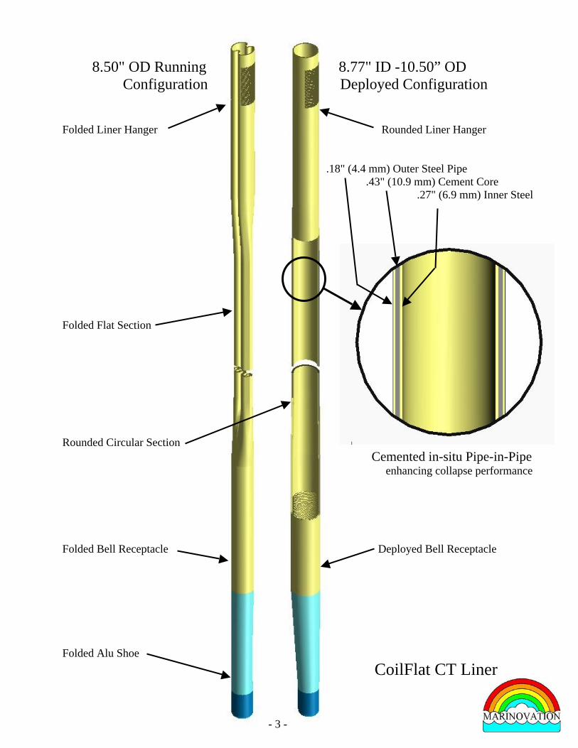
8.50" OD Running 8.77" ID -10.50” OD Configuration Deployed Configuration Folded Liner Hanger Rounded Liner Hanger
..18" (4.4 mm) Outer Steel Pipe .43" (10.9 mm) Cement Core .27" (6.9 mm) Inner Steel Folded Flat Section Rounded Circular Section Cemented in-situ Pipe-in-Pipe enhancing collapse performance Folded Bell Receptacle Deployed Bell Receptacle Folded Alu Shoe
- 3 -
CoilFlat CT Liner
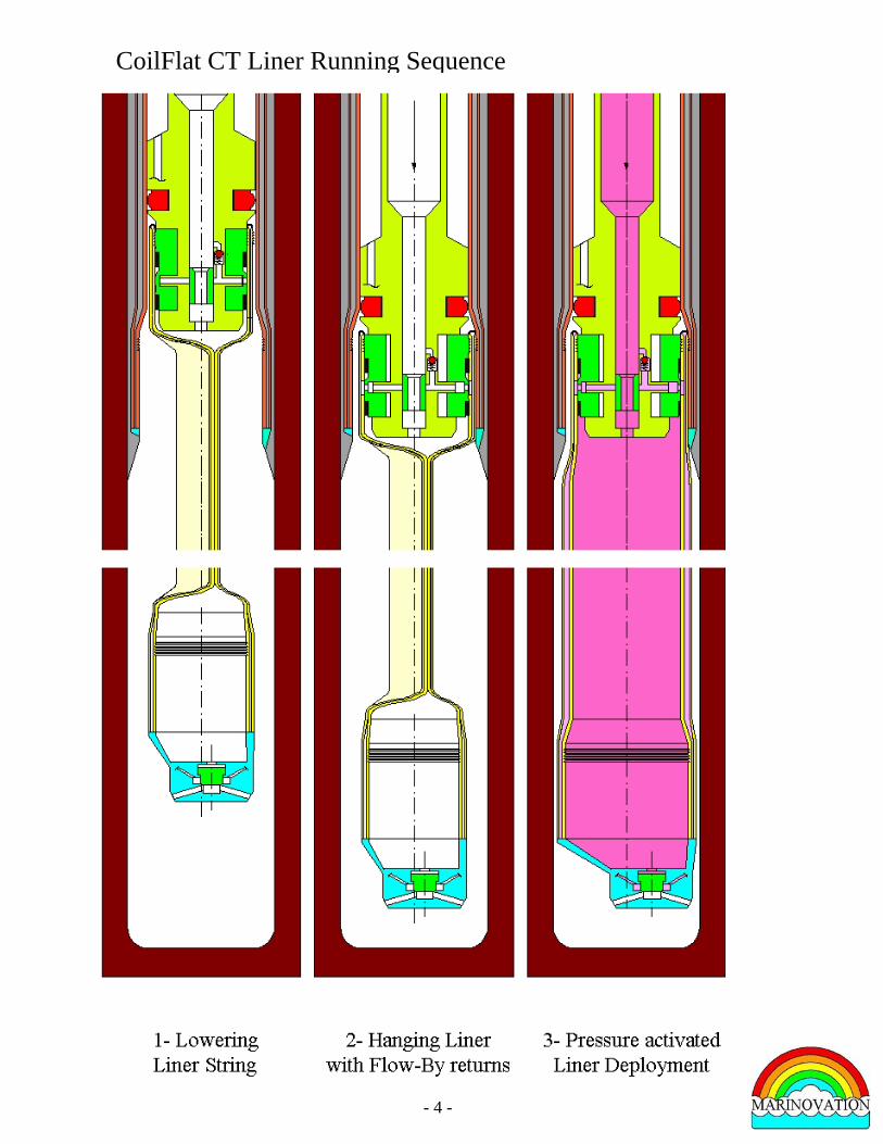
CoilFlat CT Liner Running Sequence
- 4 -

- 5 -

1- Historical Background The concept of casing a well with collapsible casing made of composite material (DrillFlex technology) was introduced in 1991 to minimize drilled volume and scale down rig size. A start-up company named DrillFlex SA was formed and substantial resources were invested in the development of the DrillFlex technology. Unfortunately, a composite product, able to compete economically against steel casing, was never achieved. Nevertheless the concept found a niche market (PatchFlex) with the capability to plug upper perforations when wells start to produce too much gas.
In 1996, the original concept was reconsidered with steel material and renamed FastWell. Successive collapsing and rounding in the plastic deformation range does not substantially affect the casing performances in pressure. The DEA (E) 96 completed in 1999 demonstrated the practicality of steel casing pressure fluid deployment but the collapse resistance of the rounded casing felt short of expectation.
In 2005, the concept was further refined with a pipe-in-pipe configuration where hardenable filling material between the pipes is displaced after rounding to enhance the collapse capability to very high level, in fact above the burst performance since the hardened cavity material provide additional compression strength.
2- Main advantages
The CoilFlat CT liner casing system will provide high collapse Monobore casing system with unlimited number of casing.
It offers the following main advantages in comparison to conventional nesting casing system : - small drilling diameter 8-1/2” x 10-5/8” all throughout the pressure containing phase of the
welll allows a major reduction of the volume drilled (up to 80% reduction) while offering a large 8-5/8” drift production casing,
- substantial reduction of steel is achieved (up to 70% reduction), - running time is shortened with the deployment of continuous coiled string, - substantial reduction of cement volume with improved quality of the cement job, - wellhead/BOP/riser size reduction from 18-3/4” to 9” and 21” to 10-3/4”
3- Technology introduction
The introduction was aiming to provide an immediate casing solution when only one single casing is required (well reentry, shallow well, multilateral, contingency, etc…) and provide a practical casing solution associated with coiled tubing drilling. But multicasing deepwater well in GOM showed recently limitation in well integrity in case of production casing incident where the CoilFlat CT liner casing system would have provided a top to bottom high pressure containing casing system with unlimited numbers of string minimizing greatly the risk exposure during drilling (no need to push drilling in awkward mud circulation situation to reach the casing shoe target anylonger!).
4- CoiFlat CT Liner construction A continuous steel strip is formed in a cylindrical configuration and welded longitudinally in a Coiled Tubing fashion. Casing hydrostatic test is performed.
The casing is then flattened and folded in a W shape and, after spacers are installed, fed into another continuous thinner steel strip formed in a cylindrical configuration which is pressed against the internal collapsed shape. The final pipe in pipe is wounded on a coiled tubing reel (road transportable) due to its small height by comparison to its deployed diameter.
- 6 -

A Stress Relief Heat Treatment “on the reel” allowing relaxation of the fabrication stresses is followed by a Quenching-Tempering to achieve adequate steel performances.
Finally on the straight outside end a bell receptacle with aluminum shoe is installed to host downhole the next casing and the inner end receives the top hanger comprising the running tool profile.
Integral cementing system can be fitted inside the folds and spread around the casing by simple rotation of the string when the string is inflated. Bottom hole temperature will trigger hardening.
5- CoilFlat CT Liner JIP Demonstration Phase 1 The aim of the Phase 1 is to confirm the targeted performances of the deployed CoilFlat CT liner.
Four test samples of CoilFlat10 will be constructed as below, and bended to the transportation reel radius of curvature.
After being straightened, hardening material (either mineral or organic) will be circulated in the pipe-in-pipe cavities, then a third party laboratory facility will be used to test the samples in collapse up to 10,000 psi followed by a burst test.
Phase 1 3rd Quarter 2010 4th Quarter 2010 Cost
1- Sample construction - Qty : 4 ------------------------------------- $ 120 k2- Qualification of Hardening material ------- ------------ $ 20 k3- Sample deployment and test ------------ $ 25 k4- Management & Contingency ------------------------------------------------ $ 15 k TOTAL $ 180 k
Operators, Steelmill, Pipe mill, Service Companies and Universities are invited to participate to the JIP in either money or kind.
It is proposed that the Participants will share the direct cost of Phase 1 ($ 180 k) and with a minimum of 3 participants the maximum cost to participate is $ 60 k ( € 48 k).
- 7 -

5- CoilFlat CT Liner JIP Demonstration Phase 2
The tasks will be : 1. Fabricate 2 straight demonstration strings of CoilFlat10 of 40 ft (12 m) length. 2. Develop and produce the liner hanger and its running/forging tool. 3. Develop and produce the collapsible hanger receptacle/shoe for Monodiameter Drilling, 4. Assemble a simulated cavity of 15 meter high to receive the demonstration strings, 5. Demonstrate the CoilFlat string deployment and cementing in the simulated cavity, 6. Pressure test internally and externally, 7. Saw cut the simulated cavity for inspection. 8. Compile a report and deliver a demonstration movie
Phase 2 1st Q 2011 2nd Q 2011 3rd Q 2011 Cost
1- CoilFlat string (2x 12m) ---------------- $ 120 k2- Liner Hanger and Running/Forging Tool ----------- ------------ $ 150 k3- Collapsible Shoe ----------- ------------ $ 80 k4- Simulated Cavity Inst. & Disposal ------ $ 60 k5- Deployment & cementing of CoilFlat --- $ 80 k6- Pressure testing and cavity sawing ---- $ 20 k7- JIP demonstration movie --------- $ 10 k8- Management & Contingency ---------------- ---------------- ------------ $ 50 k TOTAL $ 570 k
It is proposed that the Participants will share the direct cost of Phase 2 ($ 570 k) and with a minimum of 7 participants the maximum cost to participate is $ 82 k (€ 65 k).
To give a financial advantage to the Phase1 participants, it is proposed that the late participant joining at Phase 2 will pay a late entry fee equal to the Phase 1 ticket ($ 60k in case of 3 participants in Phase 1) which will be credited to the participation of Phase 2 of the first participants (in case there are 4 additional participants in Phase 2 the participation of Phase 2 will be at no charge for the first participants!)
Philippe C. Nobileau 33-6 8517 4162 - 8 - [email protected] June 23rd, 2010