
MONITORING SYSTEM FOR AN ELECTRIC VEHICLE
61
MONITORING SYSTEM FOR AN ELECTRIC VEHICLE LOW YEW HING A project report submitted in partial fulfilment of the requirements for the award of Bachelor of Engineering (Hons.) Electrical And Electronic Engineering Lee Kong Chian Faculty of Engineering and Science Universiti Tunku Abdul Rahman September 2016
Transcript of MONITORING SYSTEM FOR AN ELECTRIC VEHICLE

MONITORING SYSTEM FOR AN ELECTRIC VEHICLE
LOW YEW HING
A project report submitted in partial fulfilment of the
requirements for the award of Bachelor of Engineering
(Hons.) Electrical And Electronic Engineering
Lee Kong Chian Faculty of Engineering and Science
Universiti Tunku Abdul Rahman
September 2016

ii
DECLARATION
I hereby declare that this project report is based on my original work except for
citations and quotations which have been duly acknowledged. I also declare that it
has not been previously and concurrently submitted for any other degree or award at
UTAR or other institutions.
Signature :
Name : LOW YEW HING
ID No. : 1100894
Date : 17 SEPTEMBER 2016

iii
APPROVAL FOR SUBMISSION
I certify that this project report entitled MONITORING SYSTEM FOR AN
ELECTRIC VEHICLE was prepared by LOW YEW HING has met the required
standard for submission in partial fulfilment of the requirements for the award of
Bachelor of Engineering (Hons.) Electrical and Electronic Engineering at Universiti
Tunku Abdul Rahman.
Approved by,
Signature :
Supervisor : DR. CHEW KUEW WAI
Date :

iv
The copyright of this report belongs to the author under the terms of the
copyright Act 1987 as qualified by Intellectual Property Policy of Universiti Tunku
Abdul Rahman. Due acknowledgement shall always be made of the use of any
material contained in, or derived from, this report.
© 2016, LOW YEW HING. All right reserved.

v
ACKNOWLEDGEMENTS
First of all, I would like to express my gratitude to my research supervisor, Dr. Chew
Kuew Wai for his invaluable advice, guidance and his enormous patience throughout
the development of the research.
In addition, I would like to thank everyone who had contributed to the
successful completion of this project especially my embedded system lecturer Mr.
See Yuan Chark, and other colleagues. Besides, thanks to the University for
providing me the facilities upon completing this project.
Lastly, I would also like to express my gratitude to my loving parent and
friends who had helped and given me encouragement.

vi
MONITORING SYSTEM FOR AN ELECTRIC VEHICLE
ABSTRACT
This final year project is aim to provide a monitoring system platform for an electric
vehicle. This electric vehicle monitoring system will monitor the electric motor
temperature, power condition of electric motor, battery status, communicate and
interface with the electric motor’s electronic control unit (ECU), and some other
subsystem on the electric vehicle for example radiator and cooling fan. An
interactive and informative display shows the condition of the entire electric vehicle.
The user will be alert by the display and audio speaker but during critical condition
the monitoring system will override. The monitoring system will make appropriate
decision to prevent any further damage to the vehicle and it is concern about the
safety of the passenger. This monitoring system for electric vehicle is built up by
multiple subsystem. Each subsystem has the initiative to do data acquisition from the
sensor and send to the central processing unit. These kind of system design has the
ability to minimize sensing delay, easy troubleshoot as well as improve system
stability. The development of this electric vehicle system monitoring is focus on
implementation of an embedded based operating system Windows 10 IoT Core
Operating System, that running on Raspberry Pi 2 single-board computer (SBC).
This electrical vehicle system monitoring has a simple graphic user interface design
and a touch display which provide an interactive platform with the user. Meanwhile,
an audio speaker will be alert the user when the monitoring system is detected any
critical situation from any subsystem on the electric vehicle.

vii
TABLE OF CONTENTS
DECLARATION ii
APPROVAL FOR SUBMISSION iii
ACKNOWLEDGEMENTS iv
ABSTRACT vii
TABLE OF CONTENTS vii
LIST OF TABLES x
LIST OF FIGURES xi
LIST OF SYMBOLS / ABBREVIATIONS xiii
LIST OF APPENDICES xvv
CHAPTER
1 INTRODUCTION 1
1.1 Background 1
1.2 Aims and Objectives 2
2 LITERATURE REVIEW 3
2.1 Current Available System 3
2.2 Operating System 3
2.2.1 Microsoft 4
2.2.2 Linux 5
2.3 Single-board Computers 6
2.4 Communication Protocol 9
2.4.1 CAN Bus 9
2.4.2 I2C 11

viii
2.4.3 SPI 13
2.4.4 UART 14
2.4.5 1-wire 16
2.5 Problem Statement 17
3 METHODOLOGY 18
3.1 Overview 18
3.2 System Platform 19
3.3 Current Sub-Systems 20
3.3.1 Battery Status 20
3.3.2 Current Measurement 21
3.3.3 Cooling Fan Failure Detection System 22
3.4 Implementation of New Sub-Systems 23
3.4.1 Monitor Temperature of Electric Motor 23
3.4.2 Monitor Temperature of ECU 23
3.5 Real-Time Monitoring List 24
4 RESULTS AND DISCUSSIONS 25
4.1 Software Development 25
4.1.1 Application Programming 25
4.1.2 User Interface Programming 31
4.2 Hardware Development 32
5 CONCLUSIONS AND RECOMMENDATIONS 35
5.1 Summary 35
5.2 Conclusions 36
5.3 Future Improvement 36
5.3.1 Battery Voltage Monitoring 36
5.3.2 Access Electronic Controller Unit Information via
CAN Bus Protocol 37
5.3.3 Replace the Alarm System with Human Voice
Command 37

ix
REFERENCES 38
APPENDICES 40

x
LIST OF TABLES
TABLE TITLE PAGE
Table 2.1: Comparison of Single-board Computer 8
Table 3.1: Curtis Electric Motor ECU- 1239E’s CAN Bus Information 24
Table 3.2: Action List for Real Time Monitoring System 25
Table 3.3: Signal Source 25
xi
LIST OF FIGURES
FIGURE TITLE PAGE
Figure 2.1: Google’s Android Auto 6
Figure 2.2: Standard CAN Protocol Frame Format 11
Figure 2.3: Overview of I2C Connection 12
Figure 2.4: I2C Required Pull-up Resistor on SDA and SCL 12
Figure 2.5: I2C Data Transmission Bits 13
Figure 2.6: SPI – Master to Multiple Slave Device 14
Figure 2.7: UART Data Transmission Connection 15
Figure 2.8: UART Data Transmission Bits Frame 15
Figure 2.9: Overview of 1-wire Application 16
Figure 2.10: 1-wire Data Transmission Bits Frame 16
Figure 2.11: Steps of 1-wire Data transmission 16
Figure 3.1: Work Flow Distribution Block Diagram 19
Figure 3.2: DS2436 Circuit with Optocoupler 20
Figure 3.3: Circuit of DS2436 Sensor Module Built on PCB Board 21
Figure 3.4: Circuit connection of HTFS current sensor 21

xii
Figure 3.5: Cooling Fan Failure Detection System 22
Figure 3.6: Cooling Fan Failure Detection System 22
Figure 3.7: Curtis Electric Motor ECU- 1239E 24
Figure 4.1: Complete Circuit Schematic Diagram 32
Figure 4.2: Full Setup of the Prototype 33
Figure 4.3: Actual Circuit Construction 33
Figure 4.4: Real Time Display Screen 34
xiii
LIST OF SYMBOLS / ABBREVIATIONS
ACK Acknowledge
ADC Analogue to Digital
API Application Program Interface
ARM Advance RISC Machine
AUX Auxiliary
BJT Bipolar Junction Transistor
CAN Controller Area Network
CPU Central Processing Unit
CRC Cycle Redundancy Check
CS Chip Select
CSI Camera Serial Interface
CTS Coolant Temperature Sensor
ECU Electronic Control Unit
EV Electric Vehicle
GPU Graphic Processing Unit
GUI Graphic User Interface
GB Gigabytes
GM General Motor
GND Ground
GPIO General Purpose Input and Output
HDMI High-Definition Multimedia Interface
HTFS Hall Effect Current Transducer
I/O Input Output
I2C Inter-Integrated Circuit
IC Integrated Circuit
IoT Internet of Things
IVCS In-Vehicle Computer System
xiv
JTAG Joint Test Action Group
Kbps Kilo Bits per Second
LED Light-Emitting Diode
Mbps Mega Bits per Second
MISO Master In Slave Out
MOSFET Metal-Oxide-Semiconductor Field-effect transistor
MOSI Master Out Slave Input
MSDN Microsoft Developer Network
OEM Original Equipment Manufacturer
OS Operating System
PCI Peripheral Component Interconnect
RAM Random Access Memory
RMS Root Mean Square
RPM Revolution per Minute
RTC Real-time Clock
RTR Request Transmission Request
Rx Receive
SATA Serial AT Attachment
SBC Single-Board Computer
SCK Serial Clock Line
SCL Serial Clock Line
SDA Serial Data Line
SPI Serial Peripheral Interface
SS Slave Select
Tx Transmit
UART Universal Asynchronous Serial Receiver and Transmitter
USB Universal Serial Bus
USD US Dollar
UTAR Universiti Tunku Abdul Rahman
UWP Universal Windows Platform
XAML Extensible Application Markup Language

xv
LIST OF APPENDICES
APPENDIX TITLE PAGE
APPENDIX A Application Program Code 40
APPENDIX B XAML User Interface Program Code 45

CHAPTER 1
1 INTRODUCTION
1.1 Background
A system monitoring for an electric vehicle or conventional combustion engine
vehicle is a must for nowadays. Vehicle of today compared to the past century is
different. For the past century vehicle is mostly mechanical part built and today’s
vehicle involved of many electronics sensors and electronic controller. Introducing of
these electronics part to a conventional vehicle make it become more efficient, better
fuel consumption and higher safety regulation. Electronics component is found all
over vehicle and most of them are working independently. There is need of
monitoring system to centralize the information. Driver not just about responsible on
driving but also must well understand what their vehicle condition is. Electric
Vehicle (EV) is a trending for our next generation transportation. Electric Vehicle
involved many electronics component such as electric motor, electric motor
controller, battery, charger, regenerative braking system, current sensor, battery
temperature sensor and etc. These electronics parts is not found on conventional
vehicle. A monitoring system is needs to ensure the electric vehicle run smoothly and
effectively. (Wojdyla, 2012)
Conventional vehicle’s driver display panel only show little information for
example, engine problem, high water temperature and etc. A good system monitoring
for an electric vehicle is able to alert driver what is the specific problem and suggest
on necessary action. These can prevent unscheduled breakdown or any accident due
to vehicle problem itself.

In year 2011, Universiti Tunku Abdul Rahman started an Electric Vehicle
conversion project. A vehicle originally has an internal combustion engine and then
replaced by an electric motor. However, there is absent of monitoring system on the
electric vehicle. A monitoring system will be designed and built for this electric
vehicle project.
1.2 Aims and Objectives
• Study on vehicle monitoring system available on market
• Identify suitable operating system platform
• Identify suitable single-board computer
• Determine the possible information need to be monitor
• Design and built a real time monitoring system platform which able to alert
user when error is found

3
CHAPTER 2
2 LITERATURE REVIEW
2.1 Current Available System
Each car manufacturer offer difference In-Vehicle Computer System or In-Vehicle
Infotainment System for their vehicle and it is customized to suit their own design
language. Generally, the features provide are multimedia, voice command,
navigation, remote access to the vehicle, driver assists, vehicle driving mode, and etc.
For example, BMW’s iDrive/ConnectedDrive, Mercedes-Benz’s Mbraze2 and
Audi’s Audi MMI/Audi Connect are some of the system available on market but they
are installed on their own product only.
Basically, all the system mention above are custom made and they never
share the platform each other. The system is highly custom made due to security
issue. Users are not allow to access the internal system and it is accessible by the car
manufacturer only. Again, these practice created another problem for the driver.
Whenever there is any false indicator appear on dashboard, the owner can only send
back to the original vehicle manufacture for diagnostic (Kiley, 2015).
2.2 Operating System
From the past century, automotive industrial is all about fastest acceleration,
horsepower output and now become fuel economy, multimedia, both active and

4
passive safety feature and more. But these 21st century needs feature could not
operate without an Operating System (OS). Operating System is like our human
brain. They will decide which program code or task running before another 1. Most
of the time program code is interlinking where they are sharing same recourses or
access the same data. A smart Operating System must be introduce when deal with
complex system in a vehicle.
The next Operating System competition war is in your dashboard. Although
there are a lot of difference In-Vehicle Computer System offered by difference
manufacture but operating system that run the computer system are basically 2 types:
Microsoft and Linux. (Newcomb, 2012)
2.2.1 Microsoft
Windows Embedded Automotive 7 is an operating system design for automotive
industrial. It is an embedded system platform for car manufacturer design In-Vehicle
Computer System which allow drivers communicate with the vehicle and understand
what the status of their vehicle is. The well famous successful in-vehicle computer
system Sync by Ford is using Windows Embedded platform. Some other car
manufacturers adopt this platform are Fiat, Nissan, Kia and etc. (Tannert, 2013)
Tier-1 car manufacturer tend to look for highest security, reliable and stable
system. Microsoft is the company that come out with mature solution to fit those car
manufacturer. Windows Embedded is able to fulfil the requirement of real-time
processing. There are hundreds of sub-computer system found in a vehicle and
running million lines of programing code every minute and second. A powerful real
time operating system must be capable to handle these tasks. (Newcomb, 2012)
Internet of Things IoT, has been very popular lately. Basically, it means that
connect up the sensors surround us to cloud and enable internet access for all
machine. These will enables new business opportunities, change people lifestyle and
things far away always stay connected. (Burrus, 2014)

5
Windows 10 IoT Core is the answer to the Internet of Things by Microsoft.
Windows 10 IoT Core Operating System is designed for embedded design
development. It is optimized for Single-Board Computers such as Raspberry Pi 2 and
3 and etc. which utilizes the extensible Universal Windows Platform (UWP) API that
capable to develop infinite solution. Most importantly, it is provides good platform to
build small footprint and high effectively low cost for an industrial ready product
meanwhile capable of enterprise grade security. Although Windows 10 IoT Core is
new but they have big enough support by the community such as Stack Overflow,
MSDN Forums, Raspberry Pi Forums, and GitHub. Every platform need a
developing tools so called Integrated Development Environment IDE such as Visual
Studio. Visual Studio is a powerful and complete development tool that create and
design solution for application that run on Windows. Windows 10 IoT Core is also
support for graphic user interface GUI by Extensible Application Markup Language,
XAML. Varity of programing language is also support such as C++, C#, JavaScript
and Python. (Microsoft, 2016)
2.2.2 Linux
BlackBerry subsidiary QNX is another software that allows to running on various
platform such as ARM and x86. It is an infotainment platform support integrated
third-party application, Mobile connectivity, voice recognition, HMI and frameworks,
Navigation and software update. QNX support QT and HTML5 to create extensive
graphic user interface for difference application. It is found in Audi, BMW, Ford,
GM, Honda, Mercedes-Benz and Maserati. QNX is closely collaborate with Maserati
in 2015. They integrate all of their technology concept based on Maserati
Quattroporte GTS. (QNX, 2015) For example, sensors, camera, navigation, cloud-
based services and etc.
GENIVI is an open-source in-vehicle infotainment software. They are non-
profit organization which welcome all parties and car manufacturer to work on In-
Vehicle Infotainment Software. They will define and allow flexible definition of In-
Vehicle Infotainment System as consumer needs, partner and support across the

6
supply chain, built up the architectures and provide standard, and the most important
is allows to reuse of the framework or system to achieve a true open source
ecosystem environment. Currently car manufacturer under this collaboration includes
BMW, GM, Honda, Hyundai and Nissan. (Newcomb, 2012)
Android Auto is the latest In-Vehicle Infotainment System by Google. It is
about how a driver can be safely communicate with the car as well as connected to
the world. When the driver is on the road that’s doesn’t mean they are disconnected
to the world because there is a lot information coming in like traffic info, audio
music, social media notification, navigation and even a phone call. So, the platform
will integrated ours smartphone into the car dashboard and allow the driver handle
everything on the steering wheel. (Carter, 2016) Figure 2.1 is the interface of
Android Auto.
Figure 2.1: Google’s Android Auto
2.3 Single-board Computers
Single-board Computer is a credit card size full function computer with support of
various input device like USB, Ethernet, storage media, camera and output port like
HDMI display, AUX audio. Processing power of single-board computer is very high,

7
up to 2 GHz, quad core processor and massive of Random Access Memory, RAM up
to 4 GB. The power of single-board computer doesn’t end there, some is even
intergraded with graphic processing unit GPU. These allow render of high quality
images when graphic user interface GUI is introduce in the application.
Most importantly is, a number of general purpose I/O port, GPIO is offered
on the board which allows sensors, analogue to digital converter (ADC), bipolar
junction transistor BJT, metal-oxide-semiconductor field-effect transistor MOSFET,
LEDs and etc. Some communication protocol is also found on single-board computer
for example, Inter-Integrated Circuit I2C, Serial Peripheral Interface bus SPI, RS-232,
Controller Area Network CAN bus and etc.
Table 2.1 shows some comparison of single-board computer. Processing
power of below single-board computer is more than enough to handle normal task
but there is a highlight for HummingBoard’s i.MX6 Cortex-A9 CPU which is
automotive grade feature processor. All listed single-board computer support Linux
and Android Operating System except Raspberry Pi 2, can support on Windows 10
IoT Core. On the costing point of view, Raspberry Pi 2 is the cheaper in development
cost among other 3 computers. (Sims, 2015)

8
Table 2.1: Comparison of Single-board Computer
Device
ODROID C1 Raspberry Pi 2 HummingBoard
i2eX Creator CI20
CPU
1.5Ghz quad
core ARM
Cortex-A5 CPU
from Amlogic
900MHz quad-
core ARM
Cortex-A7 CPU
from Broadcom
1GHz i.MX6 dual-
core Cortex-A9
CPU
1.2GHz dual-
core
Imagination
MIPS32 CPU
GPU Mali-450 MP2
GPU Videocore IV GC2000
PowerVR
SGX540
Memory 1GB 1GB 1GB 1GB
Storage SD card slot or
eMMC module SD card slot SD card slot
8GB onboard
flash, SD card
slot
Connectivity
4 x USB,
microHDMI,
Gigabit
Ethernet, infra
red remote
control receiver
4 x USB, HDMI,
Ethernet,
3.5mm audio
jack
2 x USB, HDMI,
Ethernet, 3.5mm
audio jack, infra
red remote
control receiver
Ethernet,
802.11 b/g/n
Wi-Fi,
Bluetooth 4.0, 2
x USB, HDMI,
3.5mm audio
jack
OS Android, Linux Linux,
Windows 10 Linux, Android Linux, Android
Connectors
GPIO, SPI, I2C,
RTC (Real Time
Clock) backup
battery
connector
Camera
interface (CSI),
GPIO, SPI, I2C,
JTAG
Camera interface
(CSI-2), GPIO,
UART, SPI, I2C,
PCI-Express Gen
2, mSATA II, RTC
with backup
battery
Camera
interface
(ITU645
controller), 14-
pin ETAG
connector,
2 x UART, GPIO,
SPI, I2C, ADC
Price RM 230 RM 160 RM 440 RM 300
9
2.4 Communication Protocol
Communication protocol allows different devices such as computer, microcontroller,
modules and sensors communicate with each other for data exchange information. In
a vehicle there is range from 60 up to hundreds of controller exchange information in
between and the communication bus is transmitting billions of bits every minutes.
Some commonly used communication protocol are: Controller Area Network CAN
Bus, Inter-Integrated Circuit I2C, Serial Peripheral Interface SPI, Universal
Asynchronous serial Receiver and Transmitter (UART), and 1-Wire bus. In order to
work across multiple controller, sensors, and module on a vehicle, some basic
overview of these communication protocol is a must. (Patrick, 2002)
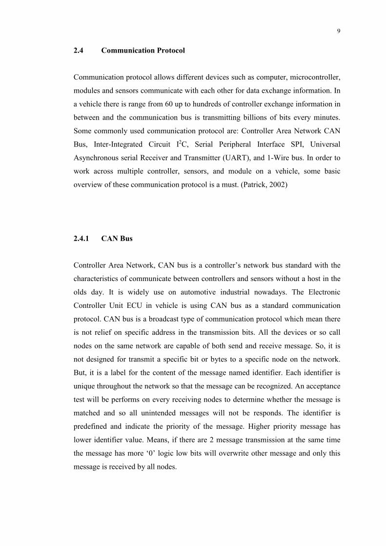
2.4.1 CAN Bus
Controller Area Network, CAN bus is a controller’s network bus standard with the
characteristics of communicate between controllers and sensors without a host in the
olds day. It is widely use on automotive industrial nowadays. The Electronic
Controller Unit ECU in vehicle is using CAN bus as a standard communication
protocol. CAN bus is a broadcast type of communication protocol which mean there
is not relief on specific address in the transmission bits. All the devices or so call
nodes on the same network are capable of both send and receive message. So, it is
not designed for transmit a specific bit or bytes to a specific node on the network.
But, it is a label for the content of the message named identifier. Each identifier is
unique throughout the network so that the message can be recognized. An acceptance
test will be performs on every receiving nodes to determine whether the message is
matched and so all unintended messages will not be responds. The identifier is
predefined and indicate the priority of the message. Higher priority message has
lower identifier value. Means, if there are 2 message transmission at the same time
the message has more ‘0’ logic low bits will overwrite other message and only this
message is received by all nodes.
10
When an electronic control unit was introduced, the fuel injection system of a
combustion engine then become electronic fuel injection. In result in better fuel
efficiency, controllable power output and controllable air pollution cause by vehicle
exhausts. There are many other sensors in an engine such as air flow sensor,
temperature sensors, piston position. All message is broadcast into CAN network and
ECU get the information from the bus. A CAN message never send from a device
directly to a specific device. It is always uses broadcast method. A CAN Controller
read bits by bits from the bus up to predefined number of data block.
Basically there are 3 common practices happen on every node. Firstly, any
undefined or failure happen the node is start to broadcast a message. Secondly, node
broadcast message continuously, for example monitoring of air flow when the engine
is running. Thirdly, a node is broadcast a message if and only if another node ask to
do so. For example, ultrasonic sensor detected a potential of collision might be
happen then broadcast a message on the CAN bus for brake assist ECU. Brake assist
ECU received such message then broadcast another message asking Engine Control
Unit to use engine braking and slow down the vehicle. It is commonly happen when
one node broadcast a message and multiple of nodes accept the message because
some information is required by multiple module or device.
CAN communication protocol is using 2 wire which are CAN High line and
CAN Low line, half duplex system. The communication rate is up to 1 Mbps but
only for a short distance like 12 Meter. Physically, CAN bus allows up to 110 nodes
connect to a network. It is capable on self-diagnose and reparation of error data.
CAN massage has 2 types of frame format for both receive and transmit,
Standard CAN protocol and Extended CAN protocol. Standard CAN frame format
consist of 7 parts. First part has 1 bit of Start of Frame (SOF). Second part has 12 bits,
an arbitration field, which provide identifier (11 bits) and Remote Transmission
Request (RTR) bit (1 bit). Third part has 6 bits, it is a Control Field with 2 reserved
bits and 4 Data Length Code. Data Length Code is a message that tell number of
bytes in the Data Field. Fourth part is Data Field which varies up to 8 Bytes. Fifth
part is CRC field which has 15 bits redundancy check-code and a recessive delimiter
bit. Sixth part has 2 bits which is Acknowledge field, the first bit is Slot bit and

11
second bit is delimiter bit. Lastly, the seventh part has 7 recessive bits which is end
of Frame field. Then the Bus is free from busy status. Figure 2.2 shows how the
entire set of CAN protocol message is.
Figure 2.2: Standard CAN Protocol Frame Format
In contrast, the Extended Frame format has two identifier bit fields instead of 1 bits
field on Arbitration which correspond of the second part out of the seven. The first
part of identifier bit fields (11 bits) is same as Standard CAN protocol but second
part is 18 bits long in result 29 bits in total compare with originally 11 bits. Other
than that, a Substitute Remote Request bit has included in Arbitration Field.
(Electronics Engineering Herald, 2006)
2.4.2 I2C
Inter-Integrated Circuit, I2C is a synchronous protocol that use only 2 wires, and it is
known as 2 wire communication. It is uses only 2 wires, one is clock line SCL
another is data line SDA connect from a Master (or host, such as microcontroller)
device to multiple Slave device (e.g. sensors) without the needs of Chip Select line
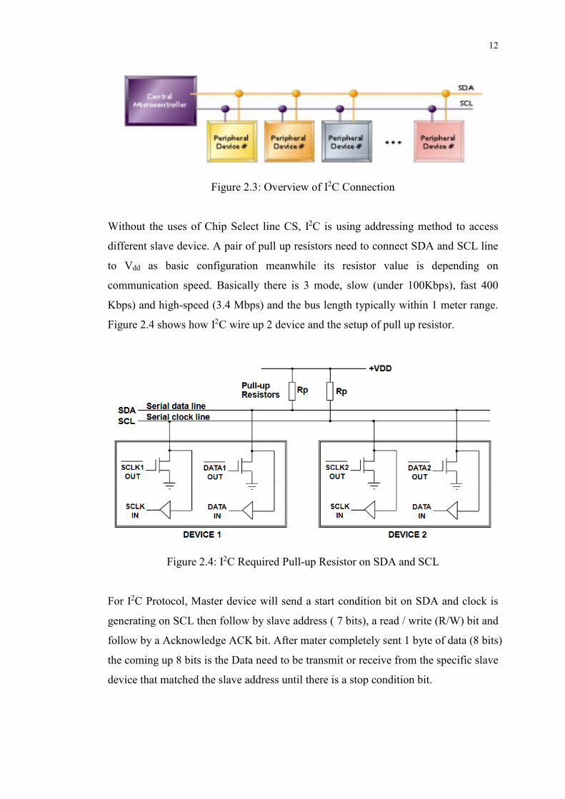
CS found on SPI communication. Figure 2.3 shows the overview of I2C connection.
12
Figure 2.3: Overview of I2C Connection
Without the uses of Chip Select line CS, I2C is using addressing method to access
different slave device. A pair of pull up resistors need to connect SDA and SCL line
to Vdd as basic configuration meanwhile its resistor value is depending on
communication speed. Basically there is 3 mode, slow (under 100Kbps), fast 400
Kbps) and high-speed (3.4 Mbps) and the bus length typically within 1 meter range.
Figure 2.4 shows how I2C wire up 2 device and the setup of pull up resistor.
Figure 2.4: I2C Required Pull-up Resistor on SDA and SCL
For I2C Protocol, Master device will send a start condition bit on SDA and clock is
generating on SCL then follow by slave address ( 7 bits), a read / write (R/W) bit and
follow by a Acknowledge ACK bit. After mater completely sent 1 byte of data (8 bits)
the coming up 8 bits is the Data need to be transmit or receive from the specific slave
device that matched the slave address until there is a stop condition bit.

13
Start condition bit is SDA’s falling edge when SCL is ‘1’ logic HIGH, Stop
condition bit is SDA’s rising edge when SCL is ‘1’ logic HIGH. For the
Acknowledge ACK bit, when the receiver ‘pull down’ SDA to ‘0’ logic LOW
meanwhile the transmitter leave SDA ‘1’ logic HIGH. Lastly, for a valid data
transmission, SCL is always ‘1’ logic HIGH. (Patrick, 2002) Figure 2.5 shows the
entire I2C data transmission bits.
Figure 2.5: I2C Data Transmission Bits
2.4.3 SPI
Serial Peripheral Interface SPI is another serial communication protocol but have
minimum of 3 wires and maximum of 4 wire configuration. There are clock line
SCK, Master Out Slave In MOSI, Master In Slave Out MISO and Slave Select SS (or
Chip Select CS). The uniqueness of this serial communication protocol is it has Slave
Select line instead of using addressing method to communicate with specific slave
device. Another things is the master device’s output is connects to the slave device
input and master device’s input is connects to the slave device output, if there is
multiple of slave device parallel connection is allow but not for slave select line.
Each slave device need a dedicated slave select pin connected to master device’s SS
(or CS) pin or a normal general purpose input-output GPIO pin. In the event of

14
multiple slave device then same amount of extra GPIO pin is needed. Figure 2.6
shows how to wire up to multiple slave device from a master device.
Figure 2.6: SPI – Master to Multiple Slave Device
The SPI communication protocol has 4 types of mode which is based on phase and
polarity of the clock line SCK which need to first configure during the initialization
of SPI protocol. A disadvantage of SPI for small footprint or low pin-count
microcontroller might not enough for multiple slave SPI interface. (Patrick, 2002)
2.4.4 UART
Universal Asynchronous serial Receiver and Transmitter (UART) is the most simple
serial communication protocol with 2 line, transmit and receive. It is very common in
embedded world. Most of the microcontroller have UART or transmit receive pin.
Transmit line is use for transmit data whereas receive line is use for receive data.
Asynchronous mean, the interval between data strings can be undefined. Detection of
start and end of data strings is determined by the receiver, receive. Figure 2.7 shows
TX and RX communication wiring.

15
Figure 2.7: UART Data Transmission Connection
Before transmission start, configuration of frequency transmission bit knows as baud
rate, need to be fixed. When baud rate mismatch, two devices are not able to talk at
the same speed eventually all receiving data is messed up. There are other parameters
need to be configure on data reception terminal such as number of bits or frame,
number of stop bits, and parity. For a standard UART, it will transmit of 8 bits in
total, 1 ‘start’ bit, 5 ‘data’ bit, 1 ‘parity’ bit and lastly 1 ‘stop’ bit to make a
transmission complete or end. (Patrick, 2002) Figure 2.8 showing the UART data
transmission bits frame.
Figure 2.8: UART Data Transmission Bits Frame
16
2.4.5 1-wire
Maxim-Dallas Semiconductor’s 1-Wire communication protocol is an asynchronous
system and it has no protocol for multi-master. Only 1 wire is needs (and a ground)
for signalling and power, transmission rate is slow (< 1Kbps) but with advantages of
long range (up to 500m), low cost and easy implementation. Typically, it is used to
communicate with multiple device such as multiple of thermometers, sensor, and
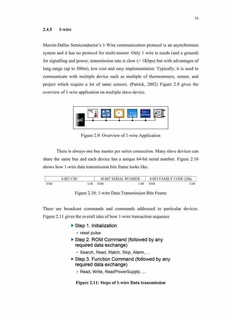
project which require a lot of same sensors. (Patrick, 2002) Figure 2.9 gives the
overview of 1-wire application on multiple slave device.
Figure 2.9: Overview of 1-wire Application
There is always one bus master per series connection. Many slave devices can
share the same bus and each device has a unique 64-bit serial number. Figure 2.10
shows how 1-wire data transmission bits frame looks like.
Figure 2.10: 1-wire Data Transmission Bits Frame
There are broadcast commands and commands addressed to particular devices.
Figure 2.11 gives the overall idea of how 1-wire transaction sequence
Figure 2.11: Steps of 1-wire Data transmission

17
2.5 Problem Statement
The Universiti Tunku Abdul Rahman Electric Vehicle Conversion project currently
has only separate module status display unit. Such as battery meter, voltage display,
current display. The electric vehicle has no complete monitoring system as a
platform allows driver to focus on 1 single display panel. It is important that driver
need to focus on road situation rather than keep looking at several separated gauge
and small segmental display.
From the perspective of driver, a platform that can centralize all the
monitored information on and single display panel with real time update is needed.
This is allows the driver can have direct information from the current status of the
electric vehicle. Meanwhile, the real time monitoring system need to be smart
enough to giving feedback, suggestion or alert to the driver when any of the monitor
reading is out of predefined value. These can prevent any breakdown happen or
further maintenance cost due to system failure.
Another suggestion is from the perspective of mechanics. A good monitoring
platform should able to help on maintenance work by logging the monitored data and
save for later analysis or tuning work. Monitor the health of component of the
electric vehicle is very important which allow maintenance work to be done in
schedules and further reduce the chance of unexpected breakdown happen.

18
CHAPTER 3
3 METHODOLOGY
3.1 Overview
This project is design and built a real time monitoring system platform for an electric
vehicle. Some of the sensors and different type of electronic controller unit were
done. Unfortunately, all the sub-system are independent. So, a platform need to
gather up the signal and monitor together. Basically, the system will be able to real
time monitoring the:
• Battery status include voltage, temperature and state of charged
• Temperature of the electric motor
• Temperature of Electronic Controller Unit
• Current measurement
• Cooling fan failure system
• Information provided by the Electronic Controller Unit via CAN protocol
This monitoring system is designed with the capability of alert user when predefined
problem is found. The flow of implementation work as shown in Figure 3.1.

19
Figure 3.1: Work Flow Distribution Block Diagram
3.2 System Platform
In-Vehicle Monitoring System is all in-house custom built by car manufacturer due
to different configuration of the vehicle. So, the author decided to create own
platform that suit Universiti Tunku Abdul Rahman’s Electric Vehicle Conversion
Project.
Microsoft Windows 10 IoT Core is the operating system of this monitoring
system platform. It is designed for embedded design development and support of
graphic user interface GUI. The programing language to write the application for this
operating system has many option, such as C++, C#, JavaScript and Python. There
are also a large community support such as GitHub and MSDN. This operating
system is also internet of things IoT ready. The operating system is newly introduce
Decide the system platform:
• Operating System
• Single-board Computer
Learn Programing Language:
• Object-Oriented programing
• C#
Understand on current sub-
systems and how to link
together
Design the system circuit and
programing
Debugging
and troubleshooting
20
by Microsoft therefore it is expected some bug or lag of library support for some
high level API (Application Program Interface). However, this is sustainable
platform in near future and back support by Microsoft.
Raspberry Pi 2 is the single-board computer that run monitoring system. The
price of Raspberry Pi 2 is most low cost compare to other single-board computer. For
this development stage this is enough for the platform. Several communication
protocol like, SPI Serial Peripheral Interface, I2C Inter-integrated Circuit and UART
Universal Asynchronous Receive and Transmit. It has 17 GPIO General Purpose
Input Output pin sufficient enough for this project application.
3.3 Current Sub-Systems
3.3.1 Battery Status
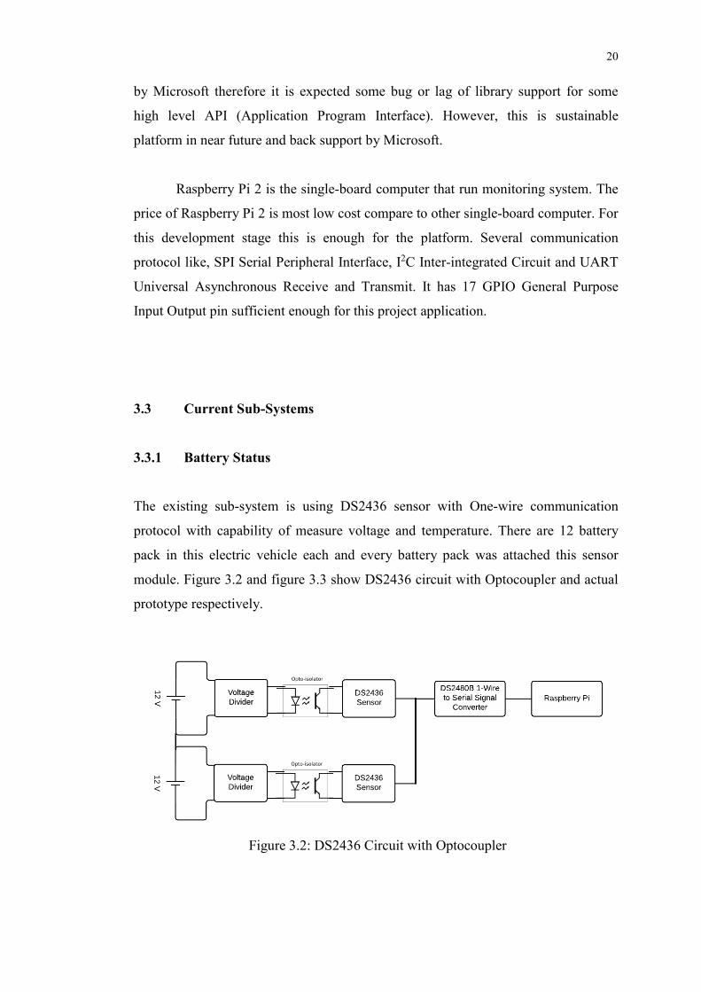
The existing sub-system is using DS2436 sensor with One-wire communication
protocol with capability of measure voltage and temperature. There are 12 battery
pack in this electric vehicle each and every battery pack was attached this sensor
module. Figure 3.2 and figure 3.3 show DS2436 circuit with Optocoupler and actual
prototype respectively.
Figure 3.2: DS2436 Circuit with Optocoupler

21
Figure 3.3: Circuit of DS2436 Sensor Module Built on PCB Board
3.3.2 Current Measurement
A Hall Effect current transducer by LEM, which can measured up to 600 ampere
(LEM, 2015) is placed on the summing battery pack terminal to measure the total
current flow. Figure 3.4 shows the circuit connection of HTFS current sensor.
Figure 3.4: Circuit connection of HTFS current sensor

22
3.3.3 Cooling Fan Failure Detection System
The Cooling Fan Failure Detection System is reports several information such as
coolant temperature, cooling fan speed in rpm, fan failure, coolant temperature
sensor CTS failure and relay failure. Currently the sub-system is controlled by
Arduino. Figure 3.5 and Figure 3.6 shows the cooling fan failure detection system
prototype.
Figure 3.5: Cooling Fan Failure Detection System
Figure 3.6: Cooling Fan Failure Detection System 2
23
3.4 Implementation of New Sub-Systems
3.4.1 Monitor Temperature of Electric Motor
Monitor the working temperature of electric motor can ensure it is operate at desire
and health operation. An automotive grade temperature sensor MCP9700 by
Microchip is selected for this application. MCP9700 is a Linear Active Thermistor
Integrated Circuit (IC). It can measure from -40 degree Celsius up to 150 degree
Celsius, the accuracy is up to +/- 1 degree Celsius and low power consumption.
Signal-conditioning circuit is very important for normal resistive sensors but this
temperature sensor is unrequired. There are only 3 pins, power supply at Vdd, ground
connect at GND and Vout for analogue signal output.
Analogue signal is further feed into an ADC Analogue-to-Digital Converter.
An ADC converter the author used is MCP3008 8 channel 10 bits resolution with
SPI communication protocol. This ADC allows up to 8 input and, zero to 1023 step
of conversion (210).
3.4.2 Monitor Temperature of ECU
Electronic Controller Unit, ECU is the brain of an electric vehicle that regulate and
supply electricity to the electric motor. This is a very expensive controller which is
cost USD 2700 dollar. Some protection job is needs to ensure it is operate in a good
temperature condition. Basically, the sensors and ADC converters used are same
with monitor of electric motor temperature, there are MCP9700 automotive grade
linear active thermistor IC and connect to the same MCP3008 ADC chip. The
MCP3008 ADC can be share together because it can input up to 8 channel of
analogue signal. Figure 3.7 shows the actual product of Curtis electric motor ECU –
1239E.

24
Figure 3.7: Curtis Electric Motor ECU- 1239E
3.5 Real-Time Monitoring List
Table 3.2 is a list for real time monitoring components and action to be taken and
table 3.3 is the signal source reference.
Table 3.2: Action List for Real Time Monitoring System
Monitor List Action Note
Battery Current
1. Alert user with buzzer
2. Light up LED on circuit board
3. Alert user with Soft-LED on
Real-Time display screen
L
Fan Cooling System
Relay failure S-sys
CTS failure S-sys
Fan failure S-sys
Motor Temperature L
Controller Temperature L
Table 3.3: Signal Source
Signal Source
S-sys Sub-system
L Sensor

25
CHAPTER 4
4 RESULTS AND DISCUSSIONS
4.1 Software Development
The core development of this project is about REAL-TIME monitoring system. This
monitoring system has the capability of process sensor signal, process the data and
display on a LCD display all in real-time manner. Real-time monitoring system is
very important not just electric vehicle but for all automotive application.
For the software development C# programing language is used and develop
using Microsoft Visual Studio 2015. Development of software consist of 2 parts
which are application programing and user interface programing. Both can be done
on a same software development application, Microsoft Visual Studio 2015.
4.1.1 Application Programming
For the application programming with related to hardware program there are several
step must go through before the algorithm programming can be entered, which is
initialization. After reviews of all kind of communication protocol this project will be
mainly employ Serial Peripheral Interface, SPI.

26
First of all, global constant, global variable, and global function need to be start off.
The LED need to be initialize as low and assign the pin number for the LED.
private int LEDStatus = 0; //initialize the LED value private const int LED_PIN = 6; //assigned the PIN 6 for output
private GpioPin pin;
For the SPI, we need to choose which SPI chip select line’s pin to be use, and for this
project line 0 is used.
/*RaspBerry Pi2 Parameters*/
private const string SPI_CONTROLLER_NAME = "SPI0"; /* For Raspberry Pi 2, use SPI0 */
private const Int32 SPI_CHIP_SELECT_LINE = 0; /* Line 0 maps to
physical pin number 24 on the Rpi2 */
For our MCP3008 IC the sending and receiving data bytes is in 3 bytes.
byte[] readBuffer = new byte[3]; /*this is defined to hold the output
data*/
byte[] writeBuffer = new byte[3] { 0x06, 0x00, 0x00 };//00000110 00; // It is SPI port serial input pin, and is used to load channel configuration
data into the device
This is to configure RED colour of soft-LED display on screen.
private SpiDevice SpiDisplay;
private SolidColorBrush redBrush = new SolidColorBrush(Windows.UI.Colors.Red);
private SolidColorBrush grayBrush = new
SolidColorBrush(Windows.UI.Colors.LightGray);
Then, create a timer for the system and create variable with data type defined.
// create a timer private DispatcherTimer timer;
int res0;
double res1; int res2;
double res3;
int res4; int res5;
int res6;
int res7;
string res5_;
string res6_;
string res7_;
27
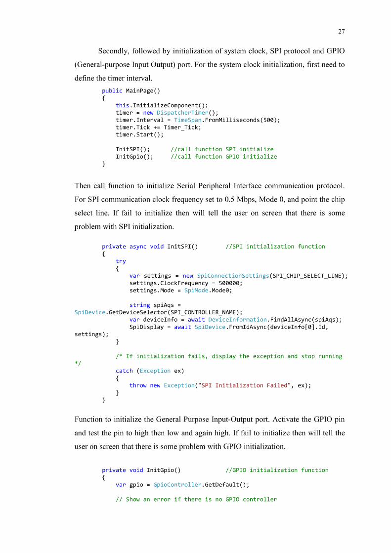
Secondly, followed by initialization of system clock, SPI protocol and GPIO
(General-purpose Input Output) port. For the system clock initialization, first need to
define the timer interval.
public MainPage()
{
this.InitializeComponent(); timer = new DispatcherTimer();
timer.Interval = TimeSpan.FromMilliseconds(500);
timer.Tick += Timer_Tick; timer.Start();
InitSPI(); //call function SPI initialize
InitGpio(); //call function GPIO initialize }
Then call function to initialize Serial Peripheral Interface communication protocol.
For SPI communication clock frequency set to 0.5 Mbps, Mode 0, and point the chip
select line. If fail to initialize then will tell the user on screen that there is some
problem with SPI initialization.
private async void InitSPI() //SPI initialization function
{ try
{
var settings = new SpiConnectionSettings(SPI_CHIP_SELECT_LINE);
settings.ClockFrequency = 500000; settings.Mode = SpiMode.Mode0;
string spiAqs = SpiDevice.GetDeviceSelector(SPI_CONTROLLER_NAME);
var deviceInfo = await DeviceInformation.FindAllAsync(spiAqs);
SpiDisplay = await SpiDevice.FromIdAsync(deviceInfo[0].Id, settings);
}
/* If initialization fails, display the exception and stop running */
catch (Exception ex)
{ throw new Exception("SPI Initialization Failed", ex);
}
}
Function to initialize the General Purpose Input-Output port. Activate the GPIO pin
and test the pin to high then low and again high. If fail to initialize then will tell the
user on screen that there is some problem with GPIO initialization.
private void InitGpio() //GPIO initialization function
{ var gpio = GpioController.GetDefault();
// Show an error if there is no GPIO controller

28
if (gpio == null)
{ pin = null;
GpioStatus.Text = "There is no GPIO controller on this
device."; return;
}
pin = gpio.OpenPin(LED_PIN);
// Show an error if the pin wasn't initialized properly if (pin == null)
{
GpioStatus.Text = "There were problems initializing the GPIO
pin."; return;
}
pin.SetDriveMode(GpioPinDriveMode.Output); pin.Write(GpioPinValue.High);
pin.Write(GpioPinValue.Low);
pin.Write(GpioPinValue.High);
GpioStatus.Text = "GPIO pin initialized correctly.";
}
After the global parameter and initialization work has done then the program
algorithm can only be continue. Send a start signal on SPI communication link, then
send 0x80 to the slave device and immediately the SPI slave device (MCP3008) will
return a bunch of bits. So, we need to call function SpiDisplay.TransferFullDuplex()
to capture the signal. Later, the signal need to convert to integer and store to variable
res0. These is repeating for another 7 times to get total of 8 data.
public void DisplayTextBoxContents()
{ writeBuffer[0] = 0x01; // set to start
writeBuffer[1] = 0x80; // set to channel 0
SpiDisplay.TransferFullDuplex(writeBuffer, readBuffer);
res0 = convertToInt(readBuffer);
But, each and every time repeating the data will be sending difference address so that
difference channel of data will be received. For example, channel 1 address is 0x90,
channel 2 address is 0xa0, channel 3 address is 0xb0, channel 4 address is 0xc0,
channel 5 address is 0xd0, channel 6 address is 0xe0, and channel 7 address is 0xf0.
writeBuffer[1] = 0x90; // set to channel 1
SpiDisplay.TransferFullDuplex(writeBuffer, readBuffer); res1 = convertToInt(readBuffer);
res1 = (((res1 / 1023) * 4.60) - 0.5) / 0.01;
writeBuffer[1] = 0xa0; // set to channel 2
SpiDisplay.TransferFullDuplex(writeBuffer, readBuffer);

29
res2 = convertToInt(readBuffer);
writeBuffer[1] = 0xb0; // set to channel 3
SpiDisplay.TransferFullDuplex(writeBuffer, readBuffer);
res3 = convertToInt(readBuffer); res3 = (((res3 / 1023) * 4.60) - 0.5) / 0.01;
writeBuffer[1] = 0xc0; // set to channel 4 SpiDisplay.TransferFullDuplex(writeBuffer, readBuffer);
res4 = convertToInt(readBuffer);
writeBuffer[1] = 0xd0; // set to channel 5
SpiDisplay.TransferFullDuplex(writeBuffer, readBuffer);
res5 = convertToInt(readBuffer);
From here will straight decide wht is the data means for, if the data return is larger
than integer value of 850 then another variable res5_ will be store string “FAIL”, else
res5_ will be store string “OK”. This is repeated for channel 5, channel 6 and channel
7.
if (res5 > 850)
{ res5_ = "FAIL";
} else
{ res5_ = "OK";
}
writeBuffer[1] = 0xe0; // set to channel 6
SpiDisplay.TransferFullDuplex(writeBuffer, readBuffer);
res6 = convertToInt(readBuffer);
if (res6 > 850)
{
res6_ = "FAIL"; }
else
{ res6_ = "OK";
}
writeBuffer[1] = 0xf0; // set to channel 7 SpiDisplay.TransferFullDuplex(writeBuffer, readBuffer);
res7 = convertToInt(readBuffer);
if (res7 > 850)
{
res7_ = "FAIL"; }
else
{ res7_ = "OK";
}
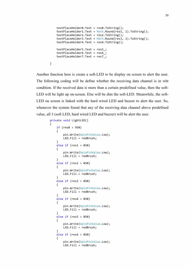
Then, store all the data received earlier to text place holder for later display on screen.
Once the data is store into text place holder it will immediately display and update on
output display. This make the information deliver in real-time manner.
30
textPlaceHolder0.Text = res0.ToString(); textPlaceHolder1.Text = Math.Round(res1, 1).ToString();
textPlaceHolder2.Text = res2.ToString();
textPlaceHolder3.Text = Math.Round(res3, 1).ToString(); textPlaceHolder4.Text = res4.ToString();
textPlaceHolder5.Text = res5_; textPlaceHolder6.Text = res6_;
textPlaceHolder7.Text = res7_;
}
Another function here is create a soft-LED to be display on screen to alert the user.
The following coding will be define whether the receiving data channel is in wht
condition. If the received data is more than a certain predefined value, then the soft-
LED will be light up on-screen. Else will be dim the soft-LED. Meanwhile, the soft-
LED on screen is linked with the hard wired LED and buzzer to alert the user. So,
whenever the system found that any of the receiving data channel above predefined
value, all 3 (soft LED, hard wired LED and buzzer) will be alert the user.
private void LightLED()
{ if (res0 > 950)
{
pin.Write(GpioPinValue.Low);
LED.Fill = redBrush; }
else if (res1 > 850)
{ pin.Write(GpioPinValue.Low);
LED.Fill = redBrush;
} else if (res2 > 850)
{
pin.Write(GpioPinValue.Low);
LED.Fill = redBrush; }
else if (res3 > 850)
{ pin.Write(GpioPinValue.Low);
LED.Fill = redBrush;
} else if (res4 > 850)
{
pin.Write(GpioPinValue.Low); LED.Fill = redBrush;
}
else if (res5 > 850)
{ pin.Write(GpioPinValue.Low);
LED.Fill = redBrush;
} else if (res6 > 850)
{
pin.Write(GpioPinValue.Low); LED.Fill = redBrush;

31
}
else if (res7 > 850) {
pin.Write(GpioPinValue.Low);
LED.Fill = redBrush; }
else
{ pin.Write(GpioPinValue.High);
LED.Fill = grayBrush;
} }
private void Timer_Tick(object sender, object e)
{ DisplayTextBoxContents();
LightLED();
}
This program is processing 8 data in real time. Beginning with the potentiometer for
test about the real time or how the system response in real time is. Secondly, is
monitor and display the temperature of Electronic Controller Unit ECU in degree
Celsius. Thirdly, is monitor of entire electrical system current in Ampere. Fourth, is
monitor and display the temperature of electric motor in degree Celsius. Fifth, is a
predefined test for always stable state condition. Sixth, is monitor of the condition of
the vehicle cooling fan system. Seventh, is monitor the health of coolant temperature
sensor. And lastly, is monitor the fault of cooling fan relay.
4.1.2 User Interface Programming
This program must be able to tell the user what is the current condition of the vehicle
he is driving and the information shown must be in real-time base and now come to
user interface programing. The program is using Extensible Application Markup
Language (.XAML) is a declarative XML-based language developed by Microsoft
that is used for initializing structured values and objects. From the earlier part,
already mention how the program pass the value to text place holder for later display
on output screen. And the full program code is listed on Appendix B: XAML User
Interface Program Code.
32
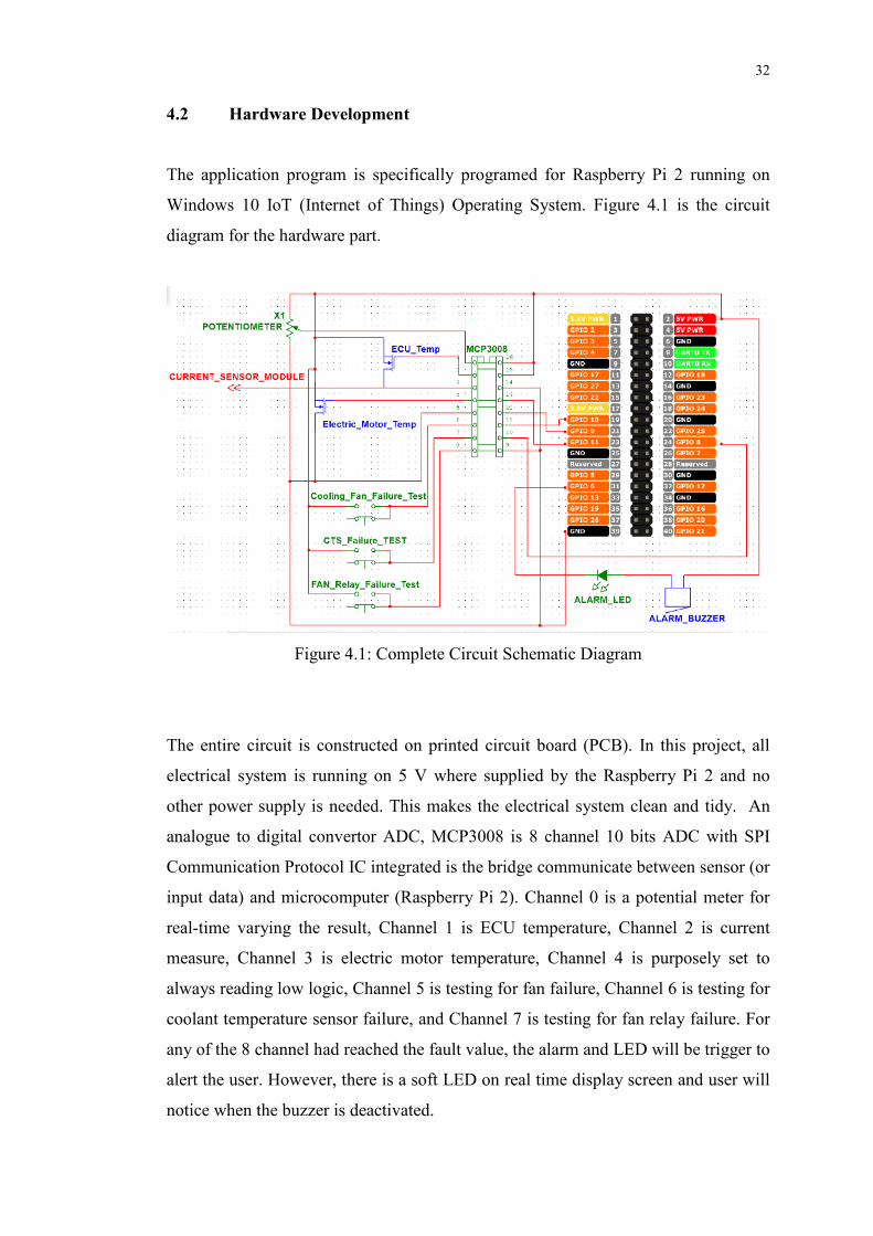
4.2 Hardware Development
The application program is specifically programed for Raspberry Pi 2 running on
Windows 10 IoT (Internet of Things) Operating System. Figure 4.1 is the circuit
diagram for the hardware part.
Figure 4.1: Complete Circuit Schematic Diagram
The entire circuit is constructed on printed circuit board (PCB). In this project, all
electrical system is running on 5 V where supplied by the Raspberry Pi 2 and no
other power supply is needed. This makes the electrical system clean and tidy. An
analogue to digital convertor ADC, MCP3008 is 8 channel 10 bits ADC with SPI
Communication Protocol IC integrated is the bridge communicate between sensor (or
input data) and microcomputer (Raspberry Pi 2). Channel 0 is a potential meter for
real-time varying the result, Channel 1 is ECU temperature, Channel 2 is current
measure, Channel 3 is electric motor temperature, Channel 4 is purposely set to
always reading low logic, Channel 5 is testing for fan failure, Channel 6 is testing for
coolant temperature sensor failure, and Channel 7 is testing for fan relay failure. For
any of the 8 channel had reached the fault value, the alarm and LED will be trigger to
alert the user. However, there is a soft LED on real time display screen and user will
notice when the buzzer is deactivated.

33
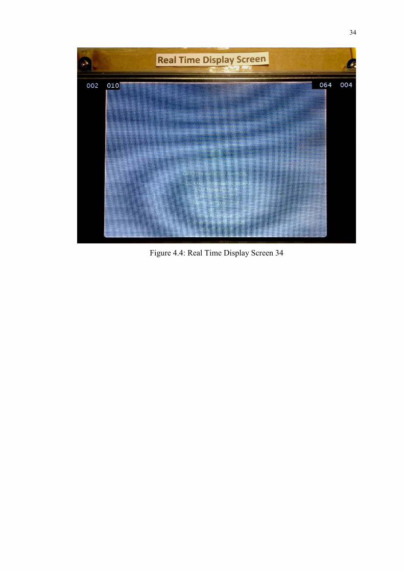
Figure 4.2, Figure 4.3, and Figure 4.4 are the photos of actual prototype.
Figure 4.2: Full Setup of the Prototype 33
Figure 4.3: Actual Circuit Construction
34
Figure 4.4: Real Time Display Screen 34
35
CHAPTER 5
5 CONCLUSIONS AND RECOMMENDATIONS
5.1 Summary
The real-time monitoring system for electric vehicle is based on Windows 10 IoT
(Internet of Things) Operating System and running on Raspberry Pi 2 single board
computer. The monitoring system has the capability of capture data, process and
output to display unit all in real-time based. This is huge improvement over the
existing system because of real-time based data process and information display.
Although the current system can only display ECU temperature, electric
motor temperature, battery current measure, analogue information reading, coolant
temperature sensor fault detection, cooling fan fault detection, and fan relay fault
detection but this project provided a very sustainable platform for future improve.
The application is programmed using C# programming language based on objected-
oriented programming language. So, the coding is well structure and organized. With
the help of Microsoft Universal Application Platform, this application can be port
into any Microsoft Windows devices in future eventually allows more developer to
join this electric vehicle monitoring system project.
36
5.2 Conclusion
The monitoring system for an electric vehicle can perform both data process and
information display in real-time based. User will be alerted by the hardware LED and
buzzer alert when any fault is found on the electric vehicle. There is also soft-LED
on LCD display to bring attention to the user when system fault is happens. The
information shown on LCD display is in real time based so that user can perform
maintenance work before any further damage on any part of the electric vehicle.
5.3 Future Improvement
The project is provide a platform that can perform real-time base data process and
display. Based on this platform there are many possible on future improvement. This
can be centralize all information into a single LCD display unit allows user access all
the information.
5.3.1 Battery Voltage Monitoring
The existing monitoring system with battery voltage and battery temperature monitor
but on this project they are absent. The development time needs to write a new
Application Platform Interface (API) for One-Wire Communication Protocol is very
time consuming. One-Wire Communication Protocol is a type of communication
method which only need 1 data line to bridge up to 128 slave devices. With the
adoption of this communication protocol, a number of 12 unit battery on the electric
vehicle is very practical and simplified the sensor circuit.
37
5.3.2 Access Electronic Controller Unit Information via CAN Bus Protocol
Another huge improvement can be done is accessing Electronic Controller Unit
information via CAN Bus protocols. The very advance ECU on electric vehicle is
able to provide huge useful information such as, throttle percentage, battery status,
electric motor load, electrical regenerative information, charging state of the battery,
current flow into and out going the controller. These information includes into the
monitoring system enable user to understand how the electric vehicle is performs.
5.3.3 Replace the Alarm System with Human Voice Command
Currently the alert is done using buzzer noise, soft-LED and illumination of LED
light. This Windows 10 IoT Operating Platform can support audio clip playback
where provide better user friendly command to the driver or specific information to
the driver when fault is occurs. Eventually, provide more informative system to a
general user without the need of maintenance engineer or mechanics.

38
REFERENCES
Altestore, 2014. TROJAN T-105 6V, 225AH (20HR) FLOODED LEAD ACID
BATTERY. [online] Available at: <http://www.altestore.com/store/Deep-Cycle-
Batteries/Batteries-Flooded-Lead-Acid/Trojan-T-105-6V-225AH-20HR-Flooded-
Lead-Acid-Battery/p1771/> [Accessed 16 March 2016].
Burrus Research, 2014. THE INTERNET OF THINGS IS FAR BIGGER THAN
ANYONE REALIZES. [online] Available at:
<http://www.wired.com/insights/2014/11/the-internet-of-things-bigger>
[Accessed 30 March 2016]
Carter, J., 2016. Android Auto News & Update: Google’s In-Car Operating System
Launched in 18 More Countries. [online] Available at: <
http://www.parentherald.com/articles/35364/20160406/android-auto-news-
update-google-s-car-operating-system-launched.htm> [Accessed 6 April 2016]
Electronics Engineering Herald, 2006. Controller Area Network (CAN) interface in
embedded systems. [online] Available at:
<http://www.eeherald.com/section/design-guide/esmod9.html> [Accessed 3
March 2016]
GENIVI, 2016. About GENIVI. [online] Available at: < http://www.genivi.org/about-
genivi> [Accessed 1 March 2016]
Groiß, D. R., 2014. The influence of temperature on the operation of batteries and
other electrochemical energy storage systems. [online] Available at:
<http://www.basytec.de/Literatur/temperature/DE_2002.htm> [Accessed 16
March 2016].
Javier Ibáñez Vial, J. W. D., 2004. Monitoring battery system for electric vehicle
based on one wire technology. In: IEEE Vehicular Power & Propulsion. Santiago,
6 October 2004. Santiago: Vehicle Power and Propulsion Committee.
Available at: < http://web.ing.puc.cl/~power/paperspdf/dixon/64a.pdf> [Accessed
24 March 2016].
Kiley, D., 2015. BMW, Mercedes-Benz have best in-car technology of German
makes. [online] Available at:
<http://www.chicagotribune.com/classified/automotive/sc-cons-0402-autocover-
grading-the-germans-20150327-story.html> [Accessed 10 March 2016].

39
LEM, 2015. Farnell. [online] Available at:
<http://www.farnell.com/datasheets/65377.pdf> [Accessed 9 March 2016].
Mayer, E., 2006. Serial Bus Systems in the Automobile. [online] Available at: <
http://vector.com/portal/medien/cmc/press/PTR/SerialBusSystems_Part1_Elektro
nikAutomotive_200611_PressArticle_EN.pdf> [Accessed 3 March 2016]
Microsoft, 2016. What is the Internet of Things? [online] Available at:
<https://www.microsoft.com/en-us/server-cloud/internet-of-things/default.aspx>
[Accessed 14 March 2016]
Microsoft, 2016. Develop Windows 10 IoT apps on Raspberry Pi 3 and Arduino.
[online] Available at: <https://developer.microsoft.com/en-us/windows/iot>
[Accessed 14 March 2016]
Newcomb, D., 2012. THE NEXT BIG OS WAR IS IN YOUR DASHBOARD. [online]
Available at: <http://www.wired.com/2012/12/automotive-os-war> [Accessed 10
March 2016].
Patrick, J., 2002. Serial Protocols Compared. [online] Available at:
<http://www.embedded.com/design/connectivity/4023975/Serial-Protocols-
Compared> [Accessed 3 March 2016]
QNX, 2015. QNX CAR Platform for Infotainment. [online] Available at: <
http://www.qnx.com/products/qnxcar/index.html> [Accessed 1 March 2016]
Sims, G., 2015. Showdown: Raspberry Pi 2 vs ODROID C1 vs HummingBoard vs
MIPS Creator C120 (updated). [online] Available at: <
http://www.androidauthority.com/raspberry-pi-2-vs-odroid-c1-vs-hummingboard-
vs-mips-creator-ci20-599418> [Accessed 2 March 2016]
Tannert, C., 2013. Microsoft wants one automotive OS to rule them all. [online]
Available at: <http://www.roadandtrack.com/new-cars/news/a4435/go-news-
microsoft-wants-one-automotive-os-to-be-windows> [Accessed 11 March 2016]
Teixeira, S., 2015. Hello, Windows 10 IoT Core. [blog] 10 August 2015 Available at:
<https://blogs.windows.com/buildingapps/2015/08/10/hello-windows-10-iot-
core> [Accessed 14 March 2016]
Wojdyla, B., 2012. How it Works: The Computer Inside Your Car. [online] Available
at: <http://www.popularmechanics.com/cars/how-to/a7386/how-it-works-the-
computer-inside-your-car> [Accessed 15 April 2016]
40
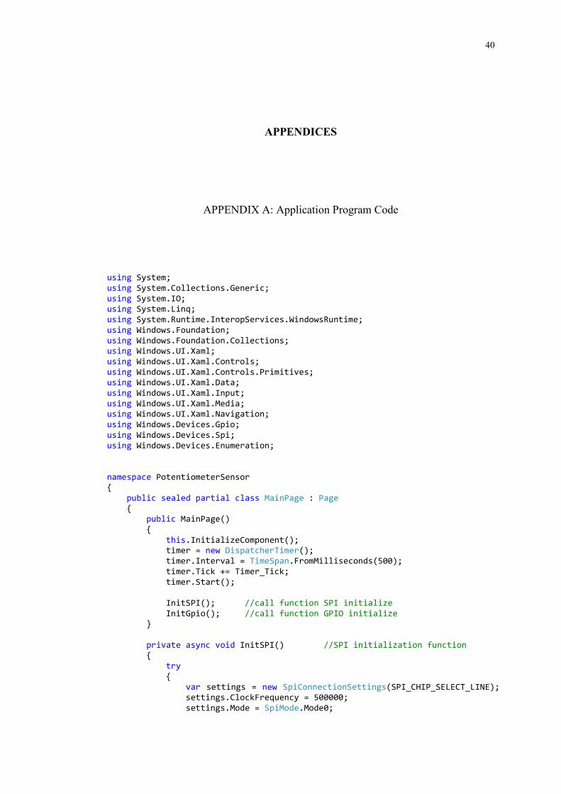
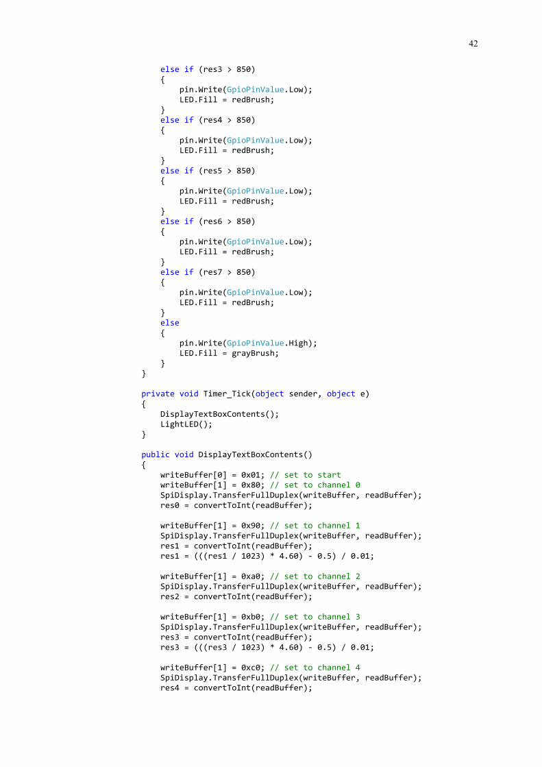
APPENDICES
APPENDIX A: Application Program Code
using System;
using System.Collections.Generic;
using System.IO; using System.Linq;
using System.Runtime.InteropServices.WindowsRuntime;
using Windows.Foundation;
using Windows.Foundation.Collections; using Windows.UI.Xaml;
using Windows.UI.Xaml.Controls;
using Windows.UI.Xaml.Controls.Primitives; using Windows.UI.Xaml.Data;
using Windows.UI.Xaml.Input;
using Windows.UI.Xaml.Media; using Windows.UI.Xaml.Navigation;
using Windows.Devices.Gpio;
using Windows.Devices.Spi;
using Windows.Devices.Enumeration;
namespace PotentiometerSensor {
public sealed partial class MainPage : Page
{ public MainPage()
{
this.InitializeComponent(); timer = new DispatcherTimer();
timer.Interval = TimeSpan.FromMilliseconds(500);
timer.Tick += Timer_Tick;
timer.Start();
InitSPI(); //call function SPI initialize
InitGpio(); //call function GPIO initialize }
private async void InitSPI() //SPI initialization function {
try
{
var settings = new SpiConnectionSettings(SPI_CHIP_SELECT_LINE); settings.ClockFrequency = 500000;
settings.Mode = SpiMode.Mode0;

41
string spiAqs =
SpiDevice.GetDeviceSelector(SPI_CONTROLLER_NAME); var deviceInfo = await DeviceInformation.FindAllAsync(spiAqs);
SpiDisplay = await SpiDevice.FromIdAsync(deviceInfo[0].Id,
settings); }
/* If initialization fails, display the exception and stop running */
catch (Exception ex)
{ throw new Exception("SPI Initialization Failed", ex);
}
}
private void InitGpio() //GPIO initialization function {
var gpio = GpioController.GetDefault();
// Show an error if there is no GPIO controller
if (gpio == null)
{ pin = null;
GpioStatus.Text = "There is no GPIO controller on this
device.";
return; }
pin = gpio.OpenPin(LED_PIN);
// Show an error if the pin wasn't initialized properly
if (pin == null) {
GpioStatus.Text = "There were problems initializing the GPIO
pin.";
return; }
pin.SetDriveMode(GpioPinDriveMode.Output);
pin.Write(GpioPinValue.High); pin.Write(GpioPinValue.Low);
pin.Write(GpioPinValue.High);
GpioStatus.Text = "GPIO pin initialized correctly.";
}
private void LightLED()
{
if (res0 > 950) {
pin.Write(GpioPinValue.Low);
LED.Fill = redBrush; }
else if (res1 > 850)
{ pin.Write(GpioPinValue.Low);
LED.Fill = redBrush;
}
else if (res2 > 850) {
pin.Write(GpioPinValue.Low);
LED.Fill = redBrush; }
42
else if (res3 > 850)
{ pin.Write(GpioPinValue.Low);
LED.Fill = redBrush;
} else if (res4 > 850)
{
pin.Write(GpioPinValue.Low); LED.Fill = redBrush;
}
else if (res5 > 850) {
pin.Write(GpioPinValue.Low);
LED.Fill = redBrush;
} else if (res6 > 850)
{
pin.Write(GpioPinValue.Low); LED.Fill = redBrush;
}
else if (res7 > 850) {
pin.Write(GpioPinValue.Low);
LED.Fill = redBrush;
} else
{
pin.Write(GpioPinValue.High); LED.Fill = grayBrush;
}
}
private void Timer_Tick(object sender, object e)
{
DisplayTextBoxContents(); LightLED();
}
public void DisplayTextBoxContents()
{
writeBuffer[0] = 0x01; // set to start writeBuffer[1] = 0x80; // set to channel 0
SpiDisplay.TransferFullDuplex(writeBuffer, readBuffer);
res0 = convertToInt(readBuffer);
writeBuffer[1] = 0x90; // set to channel 1
SpiDisplay.TransferFullDuplex(writeBuffer, readBuffer);
res1 = convertToInt(readBuffer); res1 = (((res1 / 1023) * 4.60) - 0.5) / 0.01;
writeBuffer[1] = 0xa0; // set to channel 2 SpiDisplay.TransferFullDuplex(writeBuffer, readBuffer);
res2 = convertToInt(readBuffer);
writeBuffer[1] = 0xb0; // set to channel 3
SpiDisplay.TransferFullDuplex(writeBuffer, readBuffer);
res3 = convertToInt(readBuffer);
res3 = (((res3 / 1023) * 4.60) - 0.5) / 0.01;
writeBuffer[1] = 0xc0; // set to channel 4
SpiDisplay.TransferFullDuplex(writeBuffer, readBuffer); res4 = convertToInt(readBuffer);

43
writeBuffer[1] = 0xd0; // set to channel 5
SpiDisplay.TransferFullDuplex(writeBuffer, readBuffer);
res5 = convertToInt(readBuffer);
if (res5 > 850) {
res5_ = "FAIL";
} else {
res5_ = "OK";
}
writeBuffer[1] = 0xe0; // set to channel 6
SpiDisplay.TransferFullDuplex(writeBuffer, readBuffer);
res6 = convertToInt(readBuffer);
if (res6 > 850)
{ res6_ = "FAIL";
}
else
{ res6_ = "OK";
}
writeBuffer[1] = 0xf0; // set to channel 7
SpiDisplay.TransferFullDuplex(writeBuffer, readBuffer);
res7 = convertToInt(readBuffer);
if (res7 > 850)
{
res7_ = "FAIL"; }
else
{ res7_ = "OK";
}
textPlaceHolder0.Text = res0.ToString();
textPlaceHolder1.Text = Math.Round(res1, 1).ToString();
textPlaceHolder2.Text = res2.ToString(); textPlaceHolder3.Text = Math.Round(res3, 1).ToString();
textPlaceHolder4.Text = res4.ToString();
textPlaceHolder5.Text = res5_; textPlaceHolder6.Text = res6_;
textPlaceHolder7.Text = res7_;
}
public int convertToInt(byte[] data)
{ int result = data[1] & 0x0F;
result <<= 8;
result += data[2];
return result; }
private int LEDStatus = 0; //initialize the LED value private const int LED_PIN = 6; //assigned the PIN 6 for output

44
private GpioPin pin;
/*RaspBerry Pi2 Parameters*/
private const string SPI_CONTROLLER_NAME = "SPI0"; /* For Raspberry
Pi 2, use SPI0 */ private const Int32 SPI_CHIP_SELECT_LINE = 0; /* Line 0 maps to
physical pin number 24 on the Rpi2 */
byte[] readBuffer = new byte[3]; /*this is defined to hold the output
data*/
byte[] writeBuffer = new byte[3] { 0x06, 0x00, 0x00 };//00000110 00; // It is SPI port serial input pin, and is used to load channel configuration
data into the device
private SpiDevice SpiDisplay; private SolidColorBrush redBrush = new
SolidColorBrush(Windows.UI.Colors.Red);
private SolidColorBrush grayBrush = new SolidColorBrush(Windows.UI.Colors.LightGray);
// create a timer private DispatcherTimer timer;
int res0;
double res1; int res2;
double res3;
int res4; int res5;
int res6;
int res7;
string res5_;
string res6_;
string res7_; }
}

45
APPENDIX B: XAML User Interface Program Code
<Page x:Class="PotentiometerSensor.MainPage"
xmlns="http://schemas.microsoft.com/winfx/2006/xaml/presentation"
xmlns:x="http://schemas.microsoft.com/winfx/2006/xaml"
xmlns:local="using:PotentiometerSensor" xmlns:d="http://schemas.microsoft.com/expression/blend/2008"
xmlns:mc="http://schemas.openxmlformats.org/markup-compatibility/2006"
mc:Ignorable="d" xmlns:igCA="http://infragistics.com/Chart"
>
<Grid VerticalAlignment="Center" HorizontalAlignment="Center"> <Border BorderBrush="BlanchedAlmond" CornerRadius="6"
BorderThickness="4" HorizontalAlignment="Left" VerticalAlignment="Top">
<Grid Background="Silver" Width="635" Height="587" > <Grid.RowDefinitions>
<RowDefinition Height="Auto"/>
<RowDefinition Height="Auto"/>
<RowDefinition Height="Auto"/> <RowDefinition Height="Auto"/>
<RowDefinition Height="Auto"/>
<RowDefinition Height="Auto"/> <RowDefinition Height="Auto"/>
<RowDefinition Height="Auto"/>
<RowDefinition Height="Auto"/> <RowDefinition Height="Auto"/>
<RowDefinition Height="Auto"/>
<RowDefinition Height="Auto"/>
</Grid.RowDefinitions> <StackPanel Orientation="Horizontal" Grid.Row="0"
HorizontalAlignment="Center">
<Image Source="Assets\Breadboard.jpg" Height="200" Stretch="Uniform" />
</StackPanel>
<StackPanel Orientation="Horizontal" Grid.Row="1" HorizontalAlignment="Center">
<Ellipse x:Name="LED" Fill="LightGray" Stroke="White"
Width="30" Height="30" Margin="5"/> </StackPanel>
<StackPanel Orientation="Horizontal" Grid.Row="2"
HorizontalAlignment="Center">
<TextBlock x:Name="GpioStatus" Text="Waiting for GPIO to be initialized" Margin="10,30,10,10" TextAlignment="Center" />
</StackPanel>
<StackPanel Orientation="Horizontal" Grid.Row="3" HorizontalAlignment="Center">
<TextBlock Text=" ADC Ch0 - Potentialmeter: "
TextAlignment="Left" /> <TextBlock x:Name="textPlaceHolder0" Text="Show Values 0
Here" TextAlignment="Right" />
</StackPanel>

46
<StackPanel Orientation="Horizontal" Grid.Row="4"
HorizontalAlignment="Center"> <TextBlock Text=" ECU Temp (C): " TextAlignment="Left"
/>
<TextBlock x:Name="textPlaceHolder1" Text="Show Values 1 Here" TextAlignment="Right" />
</StackPanel>
<StackPanel Orientation="Horizontal" Grid.Row="5" HorizontalAlignment="Center">
<TextBlock Text=" Current (Amp): " TextAlignment="Left"
/> <TextBlock x:Name="textPlaceHolder2" Text="Show Values 2
Here" TextAlignment="Right" />
</StackPanel>
<StackPanel Orientation="Horizontal" Grid.Row="6" HorizontalAlignment="Center">
<TextBlock Text=" Motor Temp (C): " TextAlignment="Left"
/> <TextBlock x:Name="textPlaceHolder3" Text="Show Values 3
Here" TextAlignment="Right" />
</StackPanel> <StackPanel Orientation="Horizontal" Grid.Row="7"
HorizontalAlignment="Center">
<TextBlock Text=" etc... : " TextAlignment="Left" />
<TextBlock x:Name="textPlaceHolder4" Text="Show Values 4 Here" TextAlignment="Right" />
</StackPanel>
<StackPanel Orientation="Horizontal" Grid.Row="8" HorizontalAlignment="Center">
<TextBlock Text=" Cooling Fan Status: "
TextAlignment="Left" /> <TextBlock x:Name="textPlaceHolder5" Text="Show Values 5
Here" TextAlignment="Right" />
</StackPanel>
<StackPanel Orientation="Horizontal" Grid.Row="9" HorizontalAlignment="Center">
<TextBlock Text=" Coolant Sensor Status: "
TextAlignment="Left" /> <TextBlock x:Name="textPlaceHolder6" Text="Show Values 6
Here" TextAlignment="Right" />
</StackPanel> <StackPanel Orientation="Horizontal" Grid.Row="10"
HorizontalAlignment="Center">
<TextBlock Text=" Relay Status: " TextAlignment="Left" />
<TextBlock x:Name="textPlaceHolder7" Text="Show Values 7
Here" TextAlignment="Right" />
</StackPanel> </Grid>
</Border>
</Grid>
</Page>