
Monitoring, Reporting, and Verification Manual for Clean ... · MONITORING, REPORTING, AND...
118
ASIAN DEVELOPMENT BANK MONITORING, REPORTING, AND VERIFICATION MANUAL FOR CLEAN DEVELOPMENT MECHANISM PROJECTS
Transcript of Monitoring, Reporting, and Verification Manual for Clean ... · MONITORING, REPORTING, AND...

ASIAN DEVELOPMENT BANK
MONITORING, REPORTING,
AND VERIFICATION MANUAL
FOR CLEAN DEVELOPMENT MECHANISM PROJECTS

MONITORING, REPORTING, AND VERIFICATION MANUAL FOR CLEAN DEVELOPMENT MECHANISM PROJECTS
ASIAN DEVELOPMENT BANK

Creative Commons Attribution 3.0 IGO license (CC BY 3.0 IGO)
© 2016 Asian Development Bank6 ADB Avenue, Mandaluyong City, 1550 Metro Manila, PhilippinesTel +63 2 632 4444; Fax +63 2 636 2444www.adb.org; openaccess.adb.org
Some rights reserved. Published in 2016. Printed in the Philippines.
ISBN 978-92-9257-399-7 (Print), 978-92-9257-400-0 (e-ISBN)Publication Stock No. TIM157723-2 Cataloging-In-Publication Data
Asian Development Bank. Monitoring, reporting, and veriication manual for clean development mechanism projects.Mandaluyong City, Philippines: Asian Development Bank, 2016.
1. Clean development mechanism. 2. Monitoring, reporting, and veriication. I. Asian Development Bank.
The views expressed in this publication are those of the authors and do not necessarily relect the views and policies of the Asian Development Bank (ADB) or its Board of Governors or the governments they represent.
ADB does not guarantee the accuracy of the data included in this publication and accepts no responsibility for any consequence of their use. The mention of speciic companies or products of manufacturers does not imply that they are endorsed or recommended by ADB in preference to others of a similar nature that are not mentioned.
By making any designation of or reference to a particular territory or geographic area, or by using the term “country” in this document, ADB does not intend to make any judgments as to the legal or other status of any territory or area.
This work is available under the Creative Commons Attribution 3.0 IGO license (CC BY 3.0 IGO) https://creativecommons.org/licenses/by/3.0/igo/. By using the content of this publication, you agree to be bound by the terms of said license as well as the Terms of Use of the ADB Open Access Repository at openaccess.adb.org/termsofuse
This CC license does not apply to non-ADB copyright materials in this publication. If the material is attributed to another source, please contact the copyright owner or publisher of that source for permission to reproduce it. ADB cannot be held liable for any claims that arise as a result of your use of the material.
Attribution—In acknowledging ADB as the source, please be sure to include all of the following information: Author. Year of publication. Title of the material. © Asian Development Bank [and/or Publisher].
https://openaccess.adb.org. Available under a CC BY 3.0 IGO license.
Translations—Any translations you create should carry the following disclaimer:Originally published by the Asian Development Bank in English under the title [title] © [Year of publication]
Asian Development Bank. All rights reserved. The quality of this translation and its coherence with the original text is the sole responsibility of the [translator]. The English original of this work is the only oicial version.
Adaptations—Any adaptations you create should carry the following disclaimer:This is an adaptation of an original Work © Asian Development Bank [Year]. The views expressed here are
those of the authors and do not necessarily relect the views and policies of ADB or its Board of Governors or the governments they represent. ADB does not endorse this work or guarantee the accuracy of the data included in this publication and accepts no responsibility for any consequence of their use.
Please contact [email protected] or [email protected] if you have questions or comments with respect to content, or if you wish to obtain copyright permission for your intended use that does not fall within these terms, or for permission to use the ADB logo.
Note: In this publication, “$” refers to US dollars.

CONTENTS
Tables, Figures, and Examples v
Foreword vi
Acknowledgments vii
Abbreviations viii
Executive Summary ix
Introduction 1Purpose 1Target Audience 1Latest Information 1
MODULE 1: THE CLEAN DEVELOPMENT MECHANISM 21.1 Introduction to Module 21.2 The Clean Development Mechanism 21.3 Clean Development Mechanism Projects 41.4 Clean Development Mechanism Project Cycle 81.5 Postregistration Changes 81.6 Selling Certiied Emission Reductions and the Emission Reduction Purchase Agreement 8
MODULE 2: MONITORING AND REPORTING 102.1 Introduction to Module 102.2 Monitoring, Reporting, and Veriication Deinitions and Principles 102.3 The Monitoring Framework 132.4 The Monitoring Process 162.5 Managing Required Changes to the Monitoring Plan 242.6 Monitoring Issues 25
MODULE 3: VERIFICATION 333.1 Introduction to Module 333.2 Deinition of Veriication 333.3 Timing of Veriication 343.4 How to Select and Work with a Designated Operational Entity 343.5 Designated Operational Entity Activities 353.6 Clariication Requests, Corrective Action Requests, and Forward Action Requests 373.7 Results of the Veriication and Request for Issuance 423.8 Preliminary Veriication 42

iv CONTENTS
MODULE 4: POSTREGISTRATION CHANGES 434.1 Introduction to Module 434.2 Classiication of Project Changes under the Clean Development Mechanism 434.3 When to Notify the Executive Board of Temporary or Permanent Changes 454.4 Procedure for Obtaining Approval for Temporary and Permanent Changes 49
MODULE 5: PROGRAMME OF ACTIVITIES 505.1 Introduction to Module 505.2 Programme of Activities Explained 505.3 Monitoring Process for a Programme of Activities 545.4 Revisions and Deviations to the Programme of Activities Monitoring Plan 585.5 Veriication Process for the Programme of Activities 595.6 Postregistration Changes for a Programme of Activities other than Changes
to the Monitoring Report 59
Appendixes1 Blank Monitoring Report Form 612 Sample Sustainable Development Report 673 List of Tasks and Deliverables Relevant to a Programme of Activities or Component
Project Activity 784 Monitoring Methodologies with Speciic Programme of Activities Requirements 815 Combination of Clean Development Mechanism Methodologies and Tools within a
Programme of Activities 826 Postregistration Change Request Form 847 Example Monitoring Report 89

v
Tables1 Instructions for Preparing a Monitoring Plan 152 Instructions for Completing a Monitoring Report 183 Key Calibration Deinitions 284 Explanation of Designated Operational Entity Requests in the Veriication Process: Clariication
Request, Corrective Action Request, and Forward Action Request 385 Postregistration Changes That DO NOT Require Notifying the Executive Board 436 Postregistration Changes That DO Require Notifying the Executive Board 447 Monitoring Plan Requirements for Generic and Speciic Monitoring Plans 53A3.1 Comprehensive List of Tasks and Deliverables 73A3.2 Responsibility Assignment Matrix 75A3.3 Methodologies with Speciic PoA Requirement 76
Figures1 Objectives of the Clean Development Mechanism 32 Flowchart of the Stepwise Approach 53 Eligible Clean Development Mechanism Project Types 64 Clean Development Mechanism Project Cycle 75 Monitoring, Reporting, and Veriication of Greenhouse Gas Reductions at Project Level
for Crediting Calculated Greenhouse Gas Reductions as a Diference Value 116 Monitoring, Reporting, and Veriication 127 Monitoring Process Under the Clean Development Mechanism Project Cycle 168 Items to Consider When Selecting a Designated Operational Entity 349 Designated Operational Entity Desk Review and On-Site Visit Tasks 3610 Being Prepared for Veriication 3711 Clean Development Mechanism Programme of Activities Project Cycle 49
Example1 Designated Operational Entity Corrective Action Request, Clariication Request, and Forward
Action Request Together with Project Participant Response 39
TABLES, FIGURES, AND EXAMPLES

vi
Asia and the Paciic region, hosting more than half of the world’s population, is highly vulnerable to the impacts of climate change. With rapid economic expansion in the recent years, the region has also become a major
source of greenhouse gas (GHG) emissions and therefore must play its part in cutting GHG emissions. The Paris Agreement adopted in December 2015 at the United Nations Framework Convention on Climate Change COP21 aims to restrict global warming to well below 2°C above pre-industrial levels and to pursue eforts to reach 1.5°C – which is especially relevant to Asia and the Paciic region given its vulnerability.
Enormous amount of investment is required to help developing countries transit to a low-carbon path. According to the International Energy Agency, the mitigation costs for developing countries are expected to be $140 billion–$175 billion per year by 2030. It is critical that all possible channels of inancing including policy instruments such as carbon market mechanisms are utilized to meet this requirement. Given that the Clean Development Mechanism (CDM) has been successful in mobilizing carbon inance to support mitigation actions, there is a need to maintain and further build institutional capacities for ensuring growth and enhanced efectivity of carbon markets.
Action on climate change is central to the Asian Development Bank (ADB) vision of an Asia and the Paciic free of poverty and its mission to help developing member countries (DMCs) improve the living conditions and quality of life of their people. Realizing that much work is ahead of us, ADB is continuously mobilizing and facilitating climate inance and knowledge support for its DMCs. Recently, ADB announced to double its annual climate inance from the current $3 billion to $6 billion per year by 2020. Of this, $4 billion will be for climate change mitigation and $2 billion for adaptation activities.
ADB’s Carbon Market Program (CMP) is one of the core components of its climate change program providing technical support and carbon inance to GHG mitigation projects in DMCs. The CMP includes (i) the Asia Paciic Carbon Fund; (ii) the Future Carbon Fund; and (iii) the Technical Support Facility. The Technical Support Facility (TSF) has been ADB’s main instrument to provide capacity building support for enhancing mitigation actions in its DMCs through carbon markets. The TSF has been actively engaged in providing institutional capacity development as well as project level support for the development and efective management of CDM projects in DMCs in the region. This knowledge product has been developed in line with the objectives of the regional capacity development technical assistance project: Supporting the Use of Carbon Financing to Promote Green Growth in Asia and the Paciic.
Ma. Carmela D. Locsin Director General Sustainable Development and Climate Change Department Asian Development Bank
FOREWORD
vii
ACKNOWLEDGMENTS
This knowledge product has been produced by the Technical Support Facility, a component of ADB’s Carbon Market Program under its Sustainable Development and Climate Change Department (SDCC) in
implementation of the regional capacity development technical assistance project R-CDTA 8223: Supporting the Use of Carbon Financing to Promote Green Growth in Asia and the Paciic.
Ma. Carmela D. Locsin, director general, SDCC encouraged the development of this knowledge product for the advantage of project developers in ADB’s developing member countries. Preety Bhandari, director, Climate Change and Disaster Risk Management Division (SDCD), spearheaded the overall development of this monitoring, reporting and the veriication (MRV) manual. Virender K. Duggal, senior climate change specialist (SDCD, SDCC) guided the development and inalization of this MRV manual. Jiwan Acharya, senior energy specialist, Energy Division, South Asia Department conducted a peer review and provided valuable inputs on the contents of this manual.
This publication has been prepared with technical inputs from Kate Hughes, carbon market specialist (consultant); Hemant Nandanpawar, CDM specialist (consultant); Hanh Le, carbon market expert (consultant); and Darshak Mehta, carbon market specialist (consultant). Takeshi Miyata, transaction manager (consultant) - Future Carbon Fund; Muhammad Irfan Pawennei, carbon market expert (consultant); Raymond Caguioa, carbon market expert (consultant); Ayato Kurokawa, climate inance specialist (consultant); Ha Son, carbon market expert (consultant) and Shaymal Barman, carbon market expert (consultant) provided valuable contributions - all of which are sincerely commended.

viii
ADB Asian Development Bank
CDM Clean Development Mechanism
CAR corrective action request
CER certiied emission reductions
CME coordinating/managing entity
CMP Conference of the Parties Serving as the Meeting of the Parties to the Kyoto Protocol
CO2 carbon dioxide
CPA component project activity
DMC developing member country
DOE designated operational entity
FAR forward action request
MOC modalities of communication
MRV monitoring, reporting, and veriication
MW megawatt
MWh megawatt-hour
PDD project design document
PoA Programme of Activities
PPA power purchase agreement
PRC postregistration changes
QA/QC quality assurance and quality control
UNFCCC United Nations Framework Convention on Climate Change
VVS validation and veriication standard
ABBREVIATIONS
ix
This manual has ive modules, each providing explanation on the steps and advice under the Clean Development Mechanism (CDM), from monitoring, reporting, and veriication (MRV), and issuance to
postregistration changes. A separate module is dedicated to MRV for Programme of Activities (PoA).
MODULE 1
THE CLEAN DEVELOPMENT MECHANISM
Module 1 gives a brief overview of the CDM and its key features in order to give context for MRV.
The CDM is one of three lexible mechanisms deined under the Kyoto Protocol, which was designed to enable developed countries to implement emission reduction projects in developing countries and use the emission reductions (measured in certiied emission reductions, CERs) to meet their reduction obligations. The CDM has been highly successful, with 7,664 registered projects that are estimated to have issued CERs amounting to more than 1.6 billion tons of CO
2 equivalent of emission reductions (or removals) in the period 2008–2012.
The CDM project cycle has seven stages: (i) project design; (ii) national approval; (iii) validation; (iv) registration; (v) monitoring; (vi) veriication; (vii) CER issuance. This manual is designed to assist project participants through stages v to vii, when the project is implemented, monitored, and the results are reported and veriied to qualify for CERs.
MODULE 2
MONITORING AND REPORTING
This module is designed to equip project participants with the required knowledge to manage the project MRV process as per CDM rules and procedures.
The CDM MRV process is rigorous and requires a high level of accuracy and strict data collecting and archiving, which must comply with the CDM Project Standard and other relevant standards. The information to be monitored varies between projects and between project types.
The monitoring plan will include parameters that relate to the performance of the project and parameters that relate to the calculation of emission reductions. Revisions and deviations to the monitoring plan are allowed. A deviation can only occur to the monitoring period under veriication, whereas a revision of a monitoring plan is relevant if the changes are applicable to the entire crediting period and if the changes are in the monitoring section of the project design document (PDD).
EXECUTIVE SUMMARY
x EXECUTIVE SUMMARY
The monitoring report is prepared by the project participants for a speciic monitoring period and submitted to the designated operational entity (DOE) engaged to conduct veriication and certiication of the emission reductions from the project. Simpliied step-by-step instructions for illing in the monitoring report are contained in this module.
Common issues and concerns that may arise in the monitoring process are then discussed, such as issues related to monitoring equipment, calibration of equipment, quality of data collected, and record-keeping, citing examples from an actual project. Understanding these issues, which were drawn from the collective experience of practitioners, will assist project participants to mitigate and resolve issues of their own.
MODULE 3
VERIFICATION
Module 3 provides project participants with the information required to work efectively with the DOE conducting the veriication process.
The veriication process is a thorough, independent assessment of the registered CDM project after implementation to conirm that the reductions in greenhouse gas emissions claimed for a CDM project over a deined period of time (a veriication period) are true and correct.
DOE engagement is one of the most important tasks for the project participants, and items for consideration in DOE selection are presented. Timely engagement of the DOE and close coordination with them will help progress the project to the CER issuance stage. Communicating openly and in a timely fashion will assist the DOE in completing the veriication process, and project participants can also help by ensuring that the DOE has timely access to information, records, personnel, or stakeholders that the DOE requires to complete veriication. Other tips are provided on how project participants can assist the process by being prepared in order to make the process more eicient.
The DOE will apply standard auditing techniques to assess the correctness of the information provided by the project participants, including document review, interviews, cross-check of information, and test of the correctness of formulas and calculations. The process will be conducted through desk review and an on-site visit. It is important for a project participant to understand the steps taken by a DOE in order to work with them efectively. The time taken to complete veriication will vary for every project.
In most cases, the DOE will provide the draft veriication report to the project participants for their review. When reviewing, project participants should check the entire document and not only the issues raised in clariication requests, corrective action requests (CARs), and forward action requests (FARs). Detailed explanation of the clariication request, CAR, and FAR is made, as well as providing an example of DOE requests for an actual project. After completing the veriication the DOE will produce a inal veriication report and a CER certiication report. Certiication is the formal conirmation by the DOE that the emission reductions set out in the veriication report were actually achieved, which also serves as the basis for the CDM Executive Board to issue the CERs.
The idea of preliminary veriication is presented at the end of the module. It is a voluntary measure undertaken by project participants to engage a DOE, usually before the project has commenced, to ensure the project is implemented and operated according to the procedures set out in the PDD. This process provides reassurance that problems are not left unresolved until the formal veriication process, by which time they are more diicult to ix.

EXECUTIVE SUMMARY xi
MODULE 4
POSTREGISTRATION CHANGES
Changes to project design and/or project management are inevitable and in many circumstances this requires a change to the CDM documentation and/or procedures for the project. The CDM Project Standard provides guidance for managing changes and this module explains this guidance in a clear and digestible format.
There are many circumstances that lead to the need to make changes to CDM project documentation after registration. Complex postregistration changes involve changes to the project design. Changes may arise because the CDM project has been implemented with a project design diferent from the project design described in the PDD, or the project design may be altered during the project’s lifetime. Both are common, as the PDD is often prepared before project construction has commenced, and some changes are beyond the control of the project participant. Examples of these types of changes include (i) changes in the efective output capacity, (ii) the addition or removal of a component or extension of technology, (iii) the removal or addition of one site (or more) of a project activity registered with multiple sites, or (iv) changes to electricity export arrangements.
Depending on the type of change made to the project, some changes require and others do not require notiication to the Executive Board. Such details are described in tables, and several examples are also included in this module to demonstrate the diferent types of changes.
In order to obtain approval from the Executive Board for changes, the DOE is required to submit a Postregistration Changes Request Form together with supporting documents. Submission requirements and procedural steps are explained.
MODULE 5
PROGRAMME OF ACTIVITIES
This module provides guidance on the MRV processes speciic to a PoA.
A PoA provides the organizational and methodological framework for multiple CDM projects that have the same stated goal to be registered under one project registration. Once the PoA has been registered, an unlimited number of projects, known as Component Project Activities (CPAs), can be added to the PoA without having to undergo the full process of CDM validation and registration for each individual CPA.
PoA is efective in assisting smaller projects by streamlining the registration process, allows large CDM programmes to be developed, and allows for a future expansion of the programme, as the individual project activities do not need to be deined prior to registration. Under the PoA approach, a coordinating/managing entity (CME) is responsible for proposing and overseeing the implementation of the PoA.
Monitoring and veriication are also streamlined through the PoA. The CME has responsibility for preparing the monitoring report for the PoA, which includes all CPAs active under the PoA in that monitoring period. A single DOE then veriies the monitoring report, including all CPAs included in the PoA simultaneously.

xii MONITORING, REPORTING, AND VERIFICATION MANUAL FOR CLEAN DEVELOPMENT MECHANISM PROJECTS
Much of the monitoring process for a PoA is similar to the monitoring process for a stand-alone CDM project; however, a monitoring plan for PoAs must be developed at both the PoA level and the individual CPA level. While the former is a generic monitoring plan that lists the monitoring parameters and details of the QA/QC procedures that will be applied by the CME, the latter describes the parameters to be monitored and includes details on the measuring instruments.
As regard to monitoring arrangements for a PoA, the CME has additional duties above a stand-alone CDM project of monitoring the overall implementation of the monitoring plan across CPAs. Emission reductions generated by all CPAs of the PoA are to be reported in one single monitoring report by the CME, which makes it important that the monitoring plans for each CPA are as consistent as possible so that the information can be easily collated at the PoA level. Various monitoring arrangements are possible for the split of responsibilities between the CME and CPA implementer.
A robust management system is critical to the PoA veriication process to ensure that the reporting of emission reductions across CPAs is accurate and consistent. This in turn aids the DOE when conducting veriication and it can limit the size of the sample of information that the DOE will need to independently check outside of the management system.
As with stand-alone CDM projects, revisions and deviations to the PoA monitoring plan may become required, since the PoA design documents are most often prepared before the actual projects have been built and/or commissioned. A summary of the process is provided and explained in more detail in module 4.
The requirements for veriication of a stand-alone CDM project apply equally to PoA; however, the process for veriication can vary. Highlights of these diferences are presented to ensure the project participant is well prepared for the unique complexities of the PoA veriication process.
Lastly, the current CDM Project Standard does not allow postregistration design changes for a PoA as provided for the stand-alone CDM project, other than changes to the monitoring plan. Information on the design changes permitted for a PoA and further details of postregistration changes applicable to both stand-alone CDM projects and PoAs are presented in this module and module 4.

1
Purpose The purpose of this manual is to build the capacity of project participants and their teams in monitoring, reporting, and veriication (MRV) for greenhouse gas emission reduction projects registered under the Clean Development Mechanism (CDM) of the Kyoto Protocol.
The intended outcome is an increase in the number of project participants successfully managing the MRV stages of their CDM projects through to the issuance of certiied emission reductions (CERs). The manual will also guide project participants through the process for making any postregistration changes that may be required. Robust MRV will assist in maximizing the CER issuance rates possible from these CDM projects. It will also assist project participants in meeting their contractual obligations to deliver CERs where those obligations exist.
Target AudienceThe target audience for this manual is project participants and their teams—the engineers and staf managing the operation of the project as well as team members responsible for managing the CDM aspects of the project. This manual will also be useful for stakeholders within the carbon market that are interested in the MRV and/or postregistration process of CDM project management.
While this manual is prepared primarily to assist project participants of CDM projects, it aspires to be of guidance to stakeholders of other carbon mechanisms, as many of the practices and guidance in the CDM are also applicable to other areas including voluntary carbon markets; regional, national, and subnational carbon markets; bilateral mechanisms; greenhouse gas accounting; and cooperative approaches and the new mechanism established under the Paris Agreement adopted at COP21 in December 2015.
Latest InformationThe information provided in this manual is current at the date of writing, and it is advisable to monitor for new versions of any CDM-related document, which are published on the UNFCCC CDM website.
INTRODUCTION

2
1.1 INTRODUCTION TO THE MODULE
This manual is designed to assist project participants1 and their teams in managing the monitoring, reporting, and veriication (MRV) process for a Clean Development Mechanism (CDM) project.
Module 1 gives a brief overview of the CDM and its key features in order to give context for MRV. This will assist those who are responsible for MRV but who might not be familiar with the CDM through involvement in earlier stages of project development and operation.
Module 1 contains the following subsections:
1.2 The Clean Development Mechanism
1.3 Clean Development Mechanism Projects
1.4 Clean Development Mechanism Project Cycle
1.5 Postregistration Changes
1.6 Selling Certiied Emission Reductions and the Emission Reduction Purchase Agreement
1.2 THE CLEAN DEVELOPMENT MECHANISM
The CDM is one of three lexible mechanisms2 deined under the Kyoto Protocol3 to lower the overall cost of reducing greenhouse gas emissions. The lexible mechanisms recognize that while the cost of limiting emissions varies considerably between countries, the climate change impact of reducing emissions is the same regardless of where the project is located.
The CDM enables Parties with emission reduction obligations under the Kyoto Protocol to access cost-efective opportunities to reduce emissions in countries other than their own. The CDM was designed to enable Annex 1 Parties4 to implement emission reduction projects in non-Annex I5 countries and use the emission reductions, measured in certiied emission reductions (CER) to meet their own Kyoto Protocol obligations.
1 The use of the term “project participants” throughout this manual will refer to those directly responsible for MRV and their teams as appropriate. 2 The other two lexible mechanisms are Joint Implementation and Emissions Trading.3 UNFCCC. 2014. Kyoto Protocol. http://unfccc.int/kyoto_protocol/items/2830.php 4 Annex I is deined by the UN Framework Convention on Climate Change as, “industrialized countries and economies in transition.” http://unfccc.
int/parties_and_observers/items/2704.php. Commonly referred to as “developed countries.”5 Non-Annex I is deined by the UN Framework Convention on Climate Change as, “mostly developing countries.” http://unfccc.int/parties_and_
observers/items/2704.php. Commonly referred to as “developing countries.”
MODULE 1
THE CLEAN DEVELOPMENT MECHANISM
THE CLEAN DEVELOPMENT MECHANISM 3
In practice, CDM projects are developed by a range of project participants including those from Annex I countries and non-Annex I countries and the public and private sectors. The CERs are then sold or traded and used to meet emission reduction obligations under the Kyoto Protocol, other emission reduction schemes (such as the EU Emissions Trading Scheme), or for voluntary purposes.
Operational since 2006, the CDM has been highly successful with 7,664 registered projects that are estimated to have issued CERs amounting to more than 1.6 billion tons of CO
2 equivalent of emission reductions (or removals)
in the period 2008–2012.6
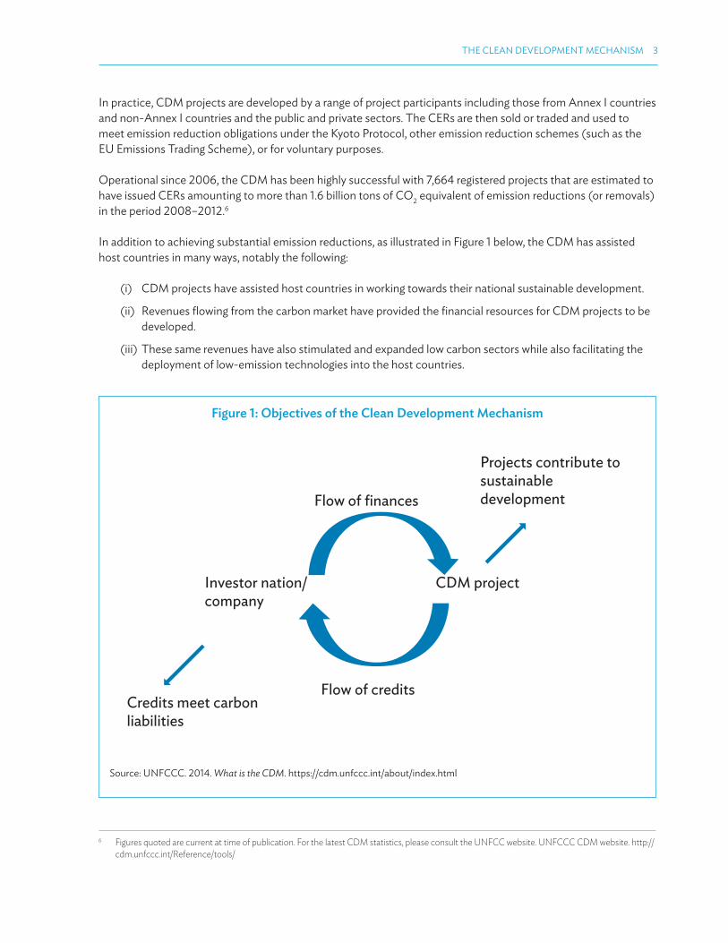
In addition to achieving substantial emission reductions, as illustrated in Figure 1 below, the CDM has assisted host countries in many ways, notably the following:
(i) CDM projects have assisted host countries in working towards their national sustainable development.
(ii) Revenues lowing from the carbon market have provided the inancial resources for CDM projects to be developed.
(iii) These same revenues have also stimulated and expanded low carbon sectors while also facilitating the deployment of low-emission technologies into the host countries.
6 Figures quoted are current at time of publication. For the latest CDM statistics, please consult the UNFCC website. UNFCCC CDM website. http://cdm.unfccc.int/Reference/tools/
Figure 1: Objectives of the Clean Development Mechanism
Credits meet carbonliabilities
Flow of credits
Flow of finances
Investor nation/company
CDM project
Projects contribute tosustainabledevelopment
Source: UNFCCC. 2014. What is the CDM. https://cdm.unfccc.int/about/index.html
4 MONITORING, REPORTING, AND VERIFICATION MANUAL FOR CLEAN DEVELOPMENT MECHANISM PROJECTS
1.3 CLEAN DEVELOPMENT MECHANISM PROJECTS
1.3.1 Clean Development Mechanism Eligibility
To be eligible under the CDM, a project is required to meet the following general eligibility criteria:
(i) A CDM project must be undertaken in a non-Annex I country that is a Party to the Kyoto Protocol.
(ii) The participation of all participants must be voluntary and approved by the Party authorizing their participation (the host country or any Annex I Party involved in the project).
(iii) Projects must lead to real, measurable, and long-term beneits related to the mitigation of climate change. These beneits are measured relative to a deined baseline.
(iv) Investment in the project by Annex I Parties or entities must not result in the diversion of oicial development assistance.
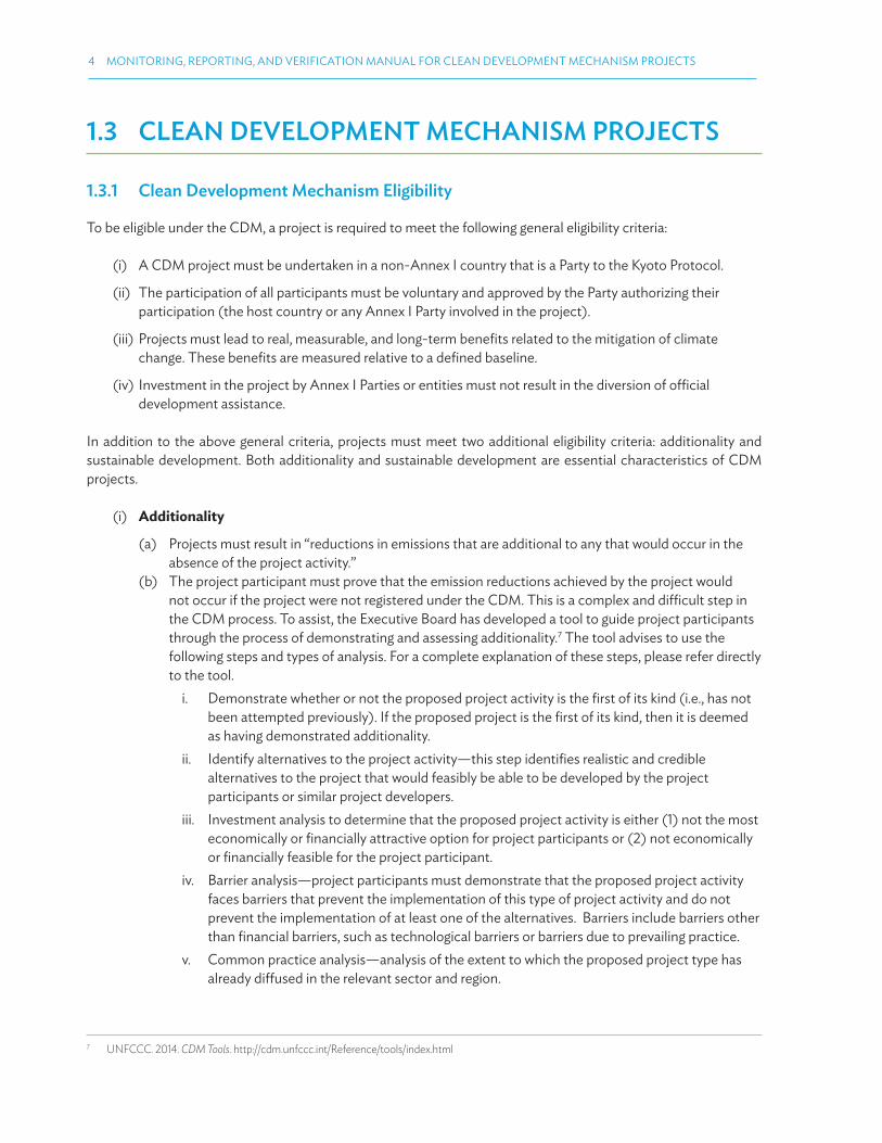
In addition to the above general criteria, projects must meet two additional eligibility criteria: additionality and sustainable development. Both additionality and sustainable development are essential characteristics of CDM projects.
(i) Additionality
(a) Projects must result in “reductions in emissions that are additional to any that would occur in the absence of the project activity.”
(b) The project participant must prove that the emission reductions achieved by the project would not occur if the project were not registered under the CDM. This is a complex and diicult step in the CDM process. To assist, the Executive Board has developed a tool to guide project participants through the process of demonstrating and assessing additionality.7 The tool advises to use the following steps and types of analysis. For a complete explanation of these steps, please refer directly to the tool.
i. Demonstrate whether or not the proposed project activity is the irst of its kind (i.e., has not been attempted previously). If the proposed project is the irst of its kind, then it is deemed as having demonstrated additionality.
ii. Identify alternatives to the project activity—this step identiies realistic and credible alternatives to the project that would feasibly be able to be developed by the project participants or similar project developers.
iii. Investment analysis to determine that the proposed project activity is either (1) not the most economically or inancially attractive option for project participants or (2) not economically or inancially feasible for the project participant.
iv. Barrier analysis—project participants must demonstrate that the proposed project activity faces barriers that prevent the implementation of this type of project activity and do not prevent the implementation of at least one of the alternatives. Barriers include barriers other than inancial barriers, such as technological barriers or barriers due to prevailing practice.
v. Common practice analysis—analysis of the extent to which the proposed project type has already difused in the relevant sector and region.
7 UNFCCC. 2014. CDM Tools. http://cdm.unfccc.int/Reference/tools/index.html

THE CLEAN DEVELOPMENT MECHANISM 5
Figure 2 demonstrates the stepwise approach used by the tool.
(ii) Sustainable Development
(a) Projects must contribute to sustainable development. Host countries determine the deinition of sustainable development—there is no common guideline used across the CDM. As part of the approval from the host country, the project participant may have to demonstrate compliance with the speciic sustainable development criteria set by that country.
Figure 2: Flowchart of the Stepwise Approach
Is the proposed project activity the first of its kind?
STEP 0: First-of-its-kind project activities
STEP 1. Identification of alternatives to the project activity consistent
with mandatory laws and regulations
STEP 2. Investment analysis
STEP 3. Barrier analysis
Does sensitivity analysis conclude that the
proposed CDM project activity is unlikely to be
the most financially attractive or is unlikely to be financially attractive?
(1) Is there at least one barrier preventing the implementation of the
proposed project activity without the CDM; and (2) Is there at least one
alternative scenario, other than proposed CDM project activity, not
prevented by any of the identified barriers?
(1) No similar activities can be observed?
(2) If similar activities are observed, are there
essential distinctions between the proposed
CDM project activity and similar activities that can reasonably be explained?
STEP 4. Common practice analysis
Project is additional
Project is not additional
N
Y
YY
N
N
N
Y
optional
Source: UNFCCC. 2014. CDM Methodological Tool. https://cdm.unfccc.int/methodologies/PAmethodologies/tools/am-tool-01-v7.0.0.pdf

6 MONITORING, REPORTING, AND VERIFICATION MANUAL FOR CLEAN DEVELOPMENT MECHANISM PROJECTS
1.3.2 Sectors Covered and Clean Development Mechanism Project Types
The scope of project types allowed under the CDM is comprehensive, covering 15 sectors based on the source categories of greenhouse gases set out in the Kyoto Protocol Annex A. Figure 3 below outlines eligible CDM project types. Examples of key project types are provided under the following igure:
Examples of CDM project types under a selection of these categories include:
(i) Energy Industries
(a) Small and large renewable energy projects (solar, wind, geothermal) that have reduced emissions intensity compared to conventional power generation.
(b) Natural gas generation and cogeneration systems that produce electricity and heat more eiciently (and hence with lower greenhouse gas emissions) than conventional natural gas generation.
(ii) Energy Distribution
Improving eiciency of transmission and distribution, e.g., transmission line voltage upgrade, transformer replacement, and increased pipe insulation in a district heating system.
(iii) Transport
Vehicle emission reductions through low greenhouse gas emitting vehicles.
Figure 3: Eligible Clean Development Mechanism Project Types
Energy Industries (Renewable/Nonrenewable)
Energy Distribution
Energy Demand
Manufacturing Industries
Chemical Industries
Construction
Transport
Mining/Mineral Production
Fugitive Emissions from Fuels (Solid, Oil, and Gas)
Fugitive Emissions from Production and Consumption of Halocarbons and Sulphur Hexafluoride
Solvent Use
Waste Handling and Disposal
A�orestation/Reforestation
Agriculture
Metal Production
Source: UNFCCC. 2014. What is the CDM. https://cdm.unfccc.int/about/index.html

THE CLEAN DEVELOPMENT MECHANISM 7
(iv) Waste Handling and Disposal
(a) Landill gas capture and combustion through laring, or for the purpose of electricity generation.(b) Composting of municipal solid waste to avoid methane emissions.
(v) Land Use, Land Use Change, and Forestry Sector8
Emissions and removals of greenhouse gases resulting from direct human-induced land use, land use change, and forestry (the absorption of carbon dioxide into carbon sinks).
Please note that nuclear energy projects and forestry projects other than aforestation and reforestation are excluded from the CDM.
8 Land use, land use change, and forestry (LULUCF) projects difer from the other categories, as they can involve emission removals as well as reductions and have very diferent processes and methodologies as well as speciic challenges. LULUCF projects are not covered in this manual.
Figure 4: Clean Development Mechanism Project Cycle
1. Project Design
2. National Approval
3. Validation
4. Registration
5. Monitoring
6. Verification
7. CER Issuance
• PP prepares project design document (PDD) using approved baseline and monitoring methodology.
• PP secures letter of approval from Designated National Authority.
• PDD is validated by accredited designated operational entity DOE .
• Validated project submitted by the DOE to CDM Executive Board with request for registration.
• PP is responsible for monitoring actual emissions according to approved methodology outlined in the PDD, for managing changes in the implementation from PDD and producing Monitoring report for DOE verification.
• DOE verifies that emission reductions that took place reflect what the Project Proponent has accounted for in monitoring plan.
• Designated operational entity submits verification report with request for issuance to CDM Executive Board.
Stages 1-4:project is
designed, and registered and the
estimate of the CERs is made
Once stage 4 is completed, the project is now a
registered “CDM project”
Stages 5-7:project is
implemented and monitored and the
results are reported and verified to
qualify for CER units
CER = certiied emission reductions, CDM = Clean Development Mechanism, PP = Project Participant.
Note: The CDM project cycle can be broken into two main sections.
Source: UNFCCC. 2014. What is the CDM. https://cdm.unfccc.int/about/index.html

8 MONITORING, REPORTING, AND VERIFICATION MANUAL FOR CLEAN DEVELOPMENT MECHANISM PROJECTS
1.4 CLEAN DEVELOPMENT MECHANISM PROJECT CYCLE
The CDM project cycle has seven stages. The irst stage is project design and the inal stage is the issuance of the CERs. Figure 4 presents the CDM project cycle.
(i) Section 1 (stages 1–4) is when the project is designed, registered, and the estimate of the CERs is made.
(ii) Section 2 (stages 5–7) is when the project is implemented (construction, commissioning, and operation), monitored, and the results are reported and veriied to qualify for CERs.
This manual is designed to assist project participants through stages 5–7: monitoring, veriication, and CER issuance.
1.5 POSTREGISTRATION CHANGES
Deviations from the project design document (PDD) submitted for registration are common—including changes in the way the project is managed and/or designed—as the PDD is most often prepared before the project has been built or commissioned. Processes for handling these changes are provided for under the CDM framework and are known as postregistration changes (PRC). PRC can occur in stages 5–7 of the CDM project cycle as noted in Figure 4. PRC requires the project participant to revisit the PDD and manage the changes accordingly.
Module 4 explains the management of these changes and adjustments in detail. Please refer to this module for necessary instructions.
1.6 SELLING CERTIFIED EMISSION REDUCTIONS AND THE EMISSION REDUCTION PURCHASE AGREEMENT
The project participant must sell the CERs from the project in order to receive inancial revenue associated with the project’s emission reductions. The transaction of CERs is done in the market, outside of the CDM process, and is not governed by the CDM Executive Board.
The legal agreement or contract that underlies the sale and purchase of CERs from CDM projects is commonly referred to as the Emission Reduction Purchase Agreement (ERPA). An ERPA should clearly deine the commercial terms of the transaction, including the type of credit being sold and purchased, price and volume, the payment and delivery mechanisms, roles and responsibilities of the seller and the buyer, and all relevant rights and obligations to manage project risks surrounding the implementation of the project. It is strongly recommended to have a robust ERPA in place to avoid any misunderstanding between parties.

THE CLEAN DEVELOPMENT MECHANISM 9
CERs sold directly from the project to a buyer are referred to as “primary CERs.”9 Project participants have three options for selling primary CERs, noting that within a single ERPA a combination of these options may be used.10
(i) Sold ahead of issuance (forward) with payment in advance (usually partial payment). This option gives the project participant (partial) inancial revenue at an earlier stage of the project (usually on a milestone basis); however, the CERs are usually sold at a lower price due to issuance risk.
(ii) Sold ahead of issuance (forward) with payment on delivery. This gives the project participant certainty that they will be able to sell the CERs from the project. However the project participant will only receive revenue once the CERs are delivered to the buyer’s account. This will occur after the project is fully operational and at least one monitoring period, veriication, and issuance cycle has occurred to receive revenue.
(iii) Sold after issuance. As the CERs are already issued, they carry minimal risk and the sale price is higher. However, the project participant must wait until the project is fully operational and at least one monitoring period, veriication, and issuance cycle has occurred to receive revenue. In addition, project participants will be facing greater volatility in terms of prices received for CERs.
CERs that are sold from one buyer to another, either in the market or through a direct transaction, are called “secondary CERs.” The secondary CERs have a very minimal risk and this commodity is traded in some exchanges. The price of secondary CERs is more transparent in the market.
Buyers of both primary and secondary CERs can include governments, intermediaries (brokers, banks), carbon funds (including multilateral development bank carbon funds), entities with compliance obligations under other schemes (e.g., European Union Emissions Trading System), and voluntary buyers.
9 Buyers of primary CERs have to have Registry Accounts entities in Annex I Party countries and are required to become a project participant to the project in order to purchase primary CERs and have them transferred to their accounts upon the sale.
10 Within a single ERPA a combination of the listed options and/or other options could be used. For example, in a single project a portion of CERs could be sold in advance and a portion sold after issuance.

10
2.1 INTRODUCTION TO THE MODULE
This module is designed to equip project participants with the required knowledge to manage the project monitoring, reporting, and veriication (MRV) process as per Clean Development Mechanism (CDM) rules and procedures. Module 2 contains the following subsections:
2.2 Monitoring, Reporting, and Veriication Deinitions and Principles
2.3 The Monitoring Framework
2.4 The Monitoring Process
2.5 Managing Required Changes to the Monitoring Plan
2.6 Monitoring Issues
Project participants should note that the monitoring plan is written prior to project registration and is contained within the project design document (PDD). Therefore, all steps within this module should be read in conjunction with the project monitoring plan. It is critical that monitoring is conducted in accordance with the PDD.
However to assist those involved in the monitoring process better understand how the monitoring plan is written and the rules and issues that may have been encountered when preparing the monitoring plan, module 2 provides an overview of the entire monitoring process for CDM projects. This includes the monitoring framework, monitoring process, and common issues that arise in the monitoring of a CDM project. Often, the team members responsible for project MRV were not involved in writing the PDD; or the PDD may be brief, or out of date. In many cases, an external consultant could have written the monitoring plan. In these cases, it will be useful for project participants and their teams to further understand the background of the monitoring framework and process.
2.2 MONITORING, REPORTING, AND VERIFICATION DEFINITIONS AND PRINCIPLES
The CDM MRV process is rigorous and requires a high level of accuracy and strict data collecting and archiving. Regardless of whether monitoring is already taking place in the project for other purposes, the MRV process for CDM projects must comply with the CDM Project Standard and other relevant standards under the CDM mechanism.11 Examples of other standards include the CDM validation and veriication standard (VVS) and the standard for sampling and surveys for CDM project activities and programme of activities.
Broadly, as the CDM is a project-based mechanism, the MRV framework discussed in this module is MRV of greenhouse gas reductions at the project level. The key feature for project-based MRV is that greenhouse gas
11 UNFCCC. 2014. CDM Standards. http://cdm.unfccc.int/Reference/Standards/index.html
MODULE 2
MONITORING AND REPORTING

MONITORING AND REPORTING 11
reductions are calculated as a “diference value” rather than as an “absolute value” of greenhouse gas emissions. Calculating this diference value requires the calculation of the greenhouse gas emissions that would occur if the project did not exist—known as “baseline emissions”—and then the reduction in emissions relative to the baseline. Figure 5 below demonstrates the calculation process.
2.2.1 Deinition of Monitoring, Reporting, and Veriication
“Monitoring, reporting, and veriication” is a widely used term both within and outside the climate change community. In the context of the CDM, the terms are deined as follows:
(i) Monitoring (or Measurement12) (M): deined as the collection and archiving of all relevant data in accordance with the project monitoring plan as described in the registered PDD, necessary for estimating or measuring greenhouse gas emissions. This includes sources covering both emissions emitted and emissions reduced or avoided through mitigation actions. Monitoring takes place within the project boundary over a deined period of time. This period of time is known as the monitoring period.
Monitoring also identiies potential sources of data and subsequently collects and archives data on increased emissions outside the project boundary (leakage). However, data is only collected if the emissions are signiicant and reasonably attributable to the project activity during the crediting period.
Monitoring, leading to the production of a monitoring report, is an essential prerequisite to veriication, certiication, and ultimately issuance.
(ii) Reporting (R): represents a commitment by the project participant to report on actual greenhouse gas emission reductions achieved by the project. Reporting is achieved through the monitoring report, which is submitted to the Designated Operational Entity (DOE) engaged to conduct veriication and certiication of the emission reductions from the project.
12 Within CDM there is occasionally diferent usage in the terminology for the “M” in MRV. The most common usage is monitoring and this manual will adopt that usage. The other usage can be measuring. Monitoring has been selected as it more accurately describes the process—a system within which measurements are being made, where the word “measuring” relates to measuring alone.
Figure 5: MRV of Greenhouse Gas Reductions at Project Level for Crediting Calculated Greenhouse Gas Reductions As A Diference Value
BaselineEmissions
ProjectEmissions
and Leakage
EmissionsReductions

12 MONITORING, REPORTING, AND VERIFICATION MANUAL FOR CLEAN DEVELOPMENT MECHANISM PROJECTS
(iii) Veriication (V): a thorough, periodic independent assessment of the CDM project ex post by a DOE to conirm that the reductions in greenhouse gas emissions claimed for a CDM project over a deined period of time (a monitoring period) are true and correct.13 The DOE that performed the veriication, shall make the monitoring report publicly available and shall inform project participants, Parties involved, and the Executive Board of its certiication decision.
Figure 6 illustrates the overview of the MRV process.
2.2.2 Principles of MRV
The following principles (in the context of CDM) should form the basis for the design and implementation of the monitoring process for a CDM project.
(i) Accuracy:
(a) Minimizing bias and uncertainty in the measurement and processing of quantitative and nonquantitative data;
(b) Reducing sources of uncertainty; and(c) Maintaining, calibrating, and checking all metering or other testing equipment used to report
monitoring data for guidance on equipment calibration and ensuring that spreadsheets and other tools used to store and manipulate monitoring data are free from error.
13 UNFCCC. 2005. Decision 3/CMP.1 Modalities and procedures for a clean development mechanism as deined in Article 12 of the Kyoto Protocol. https://cdm.unfccc.int/Reference/COPMOP/08a01.pdf#page=6
Figure 6: Monitoring, Reporting, and Veriication Process
Emissionreductions areMONITORED
Data collectedis
REPORTED
Data and procedure are VERIFIED and
CERTIFIED
• by Project Proponent
• by Project Proponent to DOE
• by the DOE to CDM Executive Board
CDM = clean development mechanism, DOE = designated operational entity.
Source: UNFCCC. 2014. What is the CDM. https://cdm.unfccc.int/about/index.html

MONITORING AND REPORTING 13
(iv) Relevance:
The monitoring and reporting of emission reductions achieved by a project is relevant information provided it complies with the CDM Project Standard. Data is not relevant if it does not impact emission reductions.
(v) Credibility:
Information can be considered credible if it is authentic and believable relative to what is being measured.
(vi) Reliability:
Information can be considered reliable if it is able to yield the same results on a repeated basis over time using the same monitoring method and datasets.
(vii) Completeness:
Completeness refers to inclusion of all relevant information for all relevant sources of data that are required for the assessment of emission reductions.
(viii) Consistency:
Data, methods, criteria, and assumptions should allow meaningful and valid comparisons of the greenhouse gas emission reductions achieved in diferent monitoring periods and/or by diferent projects.
(ix) Transparency:
Suicient information should be made publicly available to allow reviewers to make decisions on the credibility and reliability of greenhouse gas emission reduction claims with reasonable conidence.
2.3 THE MONITORING FRAMEWORK
The framework for the monitoring process is established during the PDD stage (stage 1 of the CDM project cycle). It is important that project participants follow the monitoring processes laid out in the PDD.
The PDD contains information on three key processes that are relevant to the monitoring framework: the baseline methodology, monitoring methodology, and monitoring plan.
2.3.1 Baseline Methodology
The baseline methodology is a speciic stepwise methodology for establishing the emissions that would occur in the absence of the project activity (called the baseline scenario) and calculating what you would expect these emissions to be under the baseline scenario (called the baseline emissions). The baseline methodology can be thought of as an estimation of emissions that would occur in a plausible alternative scenario to the project activity.

14 MONITORING, REPORTING, AND VERIFICATION MANUAL FOR CLEAN DEVELOPMENT MECHANISM PROJECTS
The baseline methodology is established at the PDD stage. Project participants select a methodology previously approved by the CDM Executive Board or they can establish a new methodology speciic to the project following the Modalities and Procedures for Developing a Methodology.14
Baseline methodologies vary considerably for diferent project types, but generally follow a standardized structure. The baseline methodology is used by project participants to calculate the actual emission reductions from the project, taking into account any emissions from sources within the project boundary. The baseline methodology also sets out how the monitoring plan is developed and implemented for a particular project type. The baseline methodology outlines how to collect the data required to calculate emission reductions from the project necessary for the implementation of the monitoring plan.
Project participants would have selected a baseline methodology during the PDD stage. The PDD contains a detailed section on the baseline, where the project participants apply the baseline methodology to their speciic project.
This manual is to assist project participants during monitoring and veriication; however, this subsection briely recaps the main features of methodologies to enable a better understanding of the MRV process.
2.3.2 Monitoring Methodology
The monitoring methodology sets out how project participants should develop and implement a monitoring plan for a particular project type in order to gather the data required to calculate emission reductions from the project. The monitoring methodology would have already been deined in the PDD. However, it is important that project participants understand the methodology and the information in this section in order to successfully complete the MRV process.
As with the baseline methodology, the monitoring methodology is selected at the PDD stage. Project participants select a methodology previously approved by the Executive Board or can develop a methodology speciic to the project following the Modalities and Procedures for Developing a Methodology.15
Generally, the baseline methodology and monitoring methodology are one document—so in practice, the project participant will follow the monitoring methodology linked to whichever baseline methodology it has selected.
As with the baseline methodology, monitoring methodologies vary considerably for diferent project types, but generally follow a standardized structure. The PDD has a detailed section on the monitoring methodology, where the project participant applies the methodology to their speciic project. The monitoring methodology (section B of the PDD) should contain:
(i) the title of the methodology (and standardized baseline), version number, and reference to the UNFCCC website. [section B1];
(ii) the applicability of the methodology (and standardized baseline). [section B2];
(iii) the monitoring plan [section B7] with several subsections; and
(iv) date of completion of application of methodology and standardized baseline and contact information of responsible persons/entities [section B8].
14 UNFCCC. 2006. Report of the Conference of the Parties serving as the meeting of the Parties to the Kyoto Protocol on its irst session, held at Montreal from 28 November to 10 December 2005. http://unfccc.int/resource/docs/2005/cmp1/eng/08a01.pdf
15 Footnote 14.

MONITORING AND REPORTING 15
2.3.3 Monitoring Plan
The monitoring plan, also approved at registration with the PDD, is required to monitor all parameters used to calculate the baseline, project, and leakage emissions as well as other relevant parameters required by the methodology used by the project. In accordance with the selected methodology, project participants are required to develop and design the monitoring plan for the proposed project. It is an important component of the PDD.
The monitoring plan is the source document (or guide) for the project participants to follow when completing monitoring reports once the project has commenced.
(i) Monitoring Plan Requirements
Accurate completion of the monitoring report will avoid delays at the veriication stage. To assist, the CDM Executive Board has produced guidelines on how the monitoring plan should be prepared (which will form the basis for the monitoring report to the DOE) in the CDM Project Standard. The following table summarizes these requirements, further details of which can be found in full on the UNFCC website.16
Table 1: Instructions for Preparing a Monitoring Plan
Monitoring Plan Requirements Instructions for Project Participants
Management of the monitoring plan
List the operational and management structure to be put in place to implement the monitoring plan.
Data provisions Explain the arrangements that are in place for your project that will ensure that all data monitored and required for veriication and issuance is kept and archived electronically for 2 years after the end of the crediting period or the last issuance of CERs, whichever occurs later.
Deinition of responsibilities for the data
Include a deinition of responsibilities and institutional arrangements for data collection and archiving.
QA/QC procedures Explain QA/QC procedures planned for the data, or why such procedures are not necessary.
Uncertainty levels, methods, and the associated accuracy level
State the uncertainty levels, methods, and associated accuracy level of measuring instruments to be used for various parameters and variables.
Speciications of the calibration frequency for the measuring equipment
Where there are no speciications either in the selected methodology or from the Board, project participants must ensure the equipment is calibrated in accordance with the local and/or national standards or as per the manufacturer’s speciications. If local/national standards or the manufacturer’s speciications are not available, international standards may be used.
CER = certiied emission reduction, QA/QC = quality assurance and quality control.
(ii) Sampling Plan
For CDM projects the cost of data collection and monitoring is substantial. Hence where applicable, methodologies allow the use of sampling for the determination of parameter values for calculating greenhouse gas emission reductions. Sampling plans are most common in PoAs, so guidance on sampling plans is contained in the Programme of Activities (PoA) module 5. Please refer to section 5.3 for details.
16 UNFCCC. 2014. CDM Standards. http://cdm.unfccc.int/Reference/Standards/index.html

16 MONITORING, REPORTING, AND VERIFICATION MANUAL FOR CLEAN DEVELOPMENT MECHANISM PROJECTS
(iii) How the Monitoring Plan Is Used by the DOE
During veriication, the DOE will check to ensure the monitoring plan continues to meet the requirements of the monitoring methodology and still accurately aligns with the project operation. There are various types of noncompliance, including the DOE requesting a revision to the monitoring plan before continuing with the veriication. This revision can cause a delay in the veriication of the project. Module 4: Postregistration Changes discusses these types of revisions in more detail.
2.4 THE MONITORING PROCESS
Prior to registration of the project, the project participant has established a monitoring framework in the PDD as outlined in section 2.3 above. The project participants must then follow this framework for monitoring once the project is operational.
Project participants measure, monitor, and record key information for the project in accordance with the monitoring plan that was included in the monitoring framework in the PDD. The information to be monitored varies between projects and between project types. The monitoring plan will include parameters that relate to the performance of the project and parameters that relate to the calculation of emission reductions.
Aside from the monitoring of key parameters, there are other monitoring requirements set out in the monitoring plan. Examples include QA/QC procedures and calibration of instruments. These are explained further in
Figure 7: Monitoring Process Under the Clean Development Mechanism Project Cycle
1. Project Design
2. National Approval
3. Validation
4. Registration
5. Monitoring
6. Verification
7. Certified Emissions Reduction Issuance
PP prepares PDD withmonitoring framework:
1. Baseline methodology2. Monitoring methodology3. Monitoring plan
PP starts operating the project and monitoring in accordance with the monitoring plan
PP prepares monitoring report and submits to DOE for verification
DOE = designated operational entity, PDD = project design document.
Source: UNFCCC. 2014. What is the CDM. https://cdm.unfccc.int/about/index.html

MONITORING AND REPORTING 17
subsequent sections. Figure 7 above summarizes how the monitoring process its into the CDM project cycle outlined in earlier sections.
If a change to the monitoring plan is required, the project participant must propose a revised PDD and submit for validation together with a postregistration changes form.17
Revisions and deviations to the monitoring plan are allowed. A deviation can only occur to the monitoring period under veriication. A revision of a monitoring plan is relevant if the changes are applicable to the entire crediting period and if the changes are in the monitoring section of the PDD. A revision is classiied as a PRC and can only occur if a project participant applies to the Executive Board for approval using the postregistration changes request form18 together with the revised PDD containing the revised monitoring plan. Further guidance on managing postregistration changes can be found in module 4.19
2.4.1 Monitoring Report
The monitoring report is prepared by the project participant for a speciic monitoring period and submitted to the DOE engaged to conduct veriication and certiication of the emission reductions from the project.
There are no speciic requirements as to the length of the monitoring period, so the project participants can choose based on what is convenient for them. It often makes sense for the project participant to choose a period that aligns with other reporting requirements for the project—e.g., on an annual or inancial year basis. However, project participants also need to consider the cost of the veriication process and whether the revenue from the CERs that will be potentially issued for that monitoring period is suicient to justify the cost of the veriication.
The DOE will use the monitoring report as the basis of the veriication of the particular monitoring period. Monitoring reports are completed in the approved template (similar to PDDs) and should be accompanied by supporting documentation that includes information and documentation necessary to demonstrate that the project activities comply with all applicable requirements. In addition, the monitoring report should be disclosed publicly by the DOE 14 days prior to undertaking the site visit for the veriication.
The monitoring report form is available for download from cdm.unfccc.int under Rules and References and Forms.20 The form contains the blank monitoring report template and the speciic instructions on how to complete the form. Section 2.4.2 below contains simpliied instructions for completing the monitoring report and a blank monitoring report is included in Appendix 1.
2.4.2 Simpliied Instructions for Completing the Monitoring Report
This section contains simpliied instructions for illing in the monitoring report. The instructions are drawn from the UNFCC guidelines.
The table below gives step-by-step instructions for completing the report. The table follows the prescribed sections and subsections in the UNFCC monitoring report. A blank report is included for your information in Appendix 1. A completed report is included in Appendix 7.
17 UNFCCC. 2014. Postregistration Changes Request Form. https://cdm.unfccc.int/Reference/PDDs_Forms/index.html18 Footnote 17.19 Module 5 provides clariication on when changes and deviations do or do not require project participants to notify the Executive Board.20 UNFCCC. 2014. Rules and Regulations Form. https://cdm.unfccc.int/Reference/PDDs_Forms/index.html

18 MONITORING, REPORTING, AND VERIFICATION MANUAL FOR CLEAN DEVELOPMENT MECHANISM PROJECTS
Table 2: Instructions for Completing a Monitoring Report
Monitoring Report Requirements Instructions for Project Proponent
Monitoring report cover page As per template
Title of the project activity Insert the oicial title of the project activity as per the PDD.
UNFCCC reference number of the project activity
Insert the UNFCCC reference number—this can be found in your oicial project documentation.
Version number of the monitoring report e.g., irst version = 1
Completion date of the monitoring report Use the format DD/MM/YYYY.
Monitoring period number and duration of this monitoring period
Monitoring period number and duration of the monitoring period covered in this report. The monitoring period number is an ordinal number referring to the chronological order of monitoring periods (e.g., “irst monitoring period”). For the monitoring period dates, irst and last days are included (DD/MM/YYYY – DD/MM/YYYY).
Project participant(s) Note the project participants. (Section A3 of the form will ask you to name both the Party(ies) and project participant(s) involved in the project activity).
Host Party Note the host Party of the project.
Sectoral scope(s) List all sectoral scopes applicable to the project activity (e.g., energy distribution, construction, transport, etc.).
Selected methodology(ies) List all the selected methodologies and combination methodologies applicable to the project activity.
Selected standardized baseline(s) List all selected standardized baselines applicable to the project activity.
Estimated amount of GHG emission reductions or net GHG removals by sinks for this monitoring period in the registered PDD
As per calculation
Total amount of GHG emission reductions or net GHG removals by sinks achieved in this monitoring period
GHG emission reductions or net GHG removals by sinks reported up to 31 December 2012
GHG emission reductions or net GHG removals by sinks reported from 1 January 2013 onward
Insert information here. Insert information here.
SECTION A Description of project activity
A1. Purpose and general description of project activity
The brief description should be a summary of the information contained in B1 (“Description of implemented project activity”) of the monitoring report. The summary must include the following information:(a) purpose of the project activity and the measures taken for GHG emission
reductions or net GHG removals by sinks;(b) brief description of the installed technology and equipment;(c) relevant dates for the project activity (e.g., construction, commissioning,
continued operation periods, etc.); and(d) total GHG emission reductions or net GHG removals by sinks achieved in this
monitoring period.
A2. Location of project activity Provide the following information on the location of the project activity:(a) Host Party;(b) Region/state/province, etc.;(c) City/town/community, etc.; and(d) Physical/geographic location.
continued on next page

MONITORING AND REPORTING 19
Monitoring Report Requirements Instructions for Project Proponent
A3. Parties and project participant(s) This section should include the Parties to the project including the host country and public or private entities who are involved. You should also indicate whether or not the parties involved wish to be designated as project participants. Use the following table provided in the form to assist you:
Party involved ([host] indicates a host Party)
Private and/or public entity(ies) project participants (as applicable)
Indicate whether the Party involved wished to be considered as project participant (yes/no)
Party A (host) Private entity APublic entity A
Part B Private entity APublic entity A
A4. Reference of applied methodology and standardized baseline
Indicate the exact reference (number, title, version) of the following: (a) the applied methodology(ies) (e.g., ACM0001: “Large-scale consolidated
methodology: Flaring or use of landill gas” [version 15.0]);(b) any tools and other methodologies to which the applied methodology(ies)
refers; (e.g., “Methodological tool: Tool for the demonstration and assessment of additionality” [version 07.0.0]); and
(c) the applied standardized baseline(s), where applicable (e.g., ASB0001 “Standardized baseline: Grid emission factor for the Southern African power pool” [version 01.0]).
Refer to the UNFCCC CDM website for the exact reference of the applied methodologies, tools, and standardized baselines.
A5. Crediting period of project activity
Provide the type, start date, and length of the crediting period corresponding to this monitoring period.
When applicable, the description shall also include any changes to the start date of the crediting period that have been made postregistration and have been accepted by the Executive Board.
A6. Contact information of responsible entities
Provide contact information of the person(s)/entity(ies) responsible for completing the CDM-MR-FORM, and indicate whether the person(s)/entity(ies) is(are) also a project participant(s) in Appendix 1.
You should include both telephone number and e-mail address for the relevant person(s) and entity(ies).
SECTION B Implementation of the project activity
B1. Description of implemented project activity
Provide information on the implementation status of the project activity during this monitoring period in accordance with the applicable provision for description of implemented registered CDM project activity in the Project Standard.
Include a description of the technology applied in the project activity and a detailed technical process. Include diagrams to illustrate the technical process. This section should contain signiicant detail, as you need to explain to the DOE the technical processes that form the core of your project.
This section could include the following: • a description of the aims of the project;• a description of the overall technical process and each of the subprocesses;• diagrams to illustrate the technical process and the physical layout of the plant
and/or any machinery or equipment;• description of the technology, equipment, or machinery used; • pictures or photographs of the site; and • technical parameters of technology and equipment.
For the description of the installed technology(ies), technical process, and equipment, include diagrams, where appropriate.
If applicable, present information on any request for prior approval by the Board of changes to the registered CDM project activity in sections B.2.1, B.2.2, B.2.3, B.2.4, B.2.5, and/or B.2.6.
continued on next page
Table 2 continued
20 MONITORING, REPORTING, AND VERIFICATION MANUAL FOR CLEAN DEVELOPMENT MECHANISM PROJECTS
Monitoring Report Requirements Instructions for Project Proponent
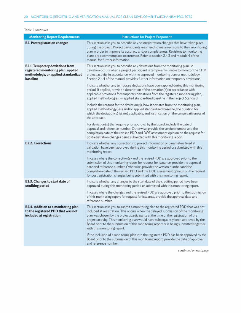
B2. Postregistration changes This section asks you to describe any postregistration changes that have taken place during the project. Project participants may need to make revisions to their monitoring plan in order to improve its accuracy and/or completeness. Revisions to monitoring plans are a commonplace occurrence. Refer to section 2.4.3 and module 4 of the manual for further information.
B2.1. Temporary deviations from registered monitoring plan, applied methodology, or applied standardized baseline
This section asks you to describe any deviations from the monitoring plan. A deviation occurs when a project participant is temporarily unable to monitor the CDM project activity in accordance with the approved monitoring plan or methodology. Section 2.4.4 of the manual provides further information on temporary deviations.
Indicate whether any temporary deviations have been applied during this monitoring period. If applied, provide a description of the deviation(s) in accordance with applicable provisions for temporary deviations from the registered monitoring plan, applied methodologies, or applied standardized baseline in the Project Standard.
Include the reasons for the deviation(s), how it deviates from the monitoring plan, applied methodology(ies) and/or applied standardized baseline, the duration for which the deviation(s) is(are) applicable, and justiication on the conservativeness of the approach.
For deviation(s) that require prior approval by the Board, include the date of approval and reference number. Otherwise, provide the version number and the completion date of the revised PDD and DOE assessment opinion on the request for postregistration changes being submitted with this monitoring report.
B2.2. Corrections Indicate whether any corrections to project information or parameters ixed at validation have been approved during this monitoring period or submitted with this monitoring report.
In cases where the correction(s) and the revised PDD are approved prior to the submission of this monitoring report for request for issuance, provide the approval date and reference number. Otherwise, provide the version number and the completion date of the revised PDD and the DOE assessment opinion on the request for postregistration changes being submitted with this monitoring report.
B2.3. Changes to start date of crediting period
Indicate whether any changes to the start date of the crediting period have been approved during this monitoring period or submitted with this monitoring report.
In cases where the changes and the revised PDD are approved prior to the submission of this monitoring report for request for issuance, provide the approval date and reference number.
B2.4. Addition to a monitoring plan to the registered PDD that was not included at registration
This section asks you to submit a monitoring plan to the registered PDD that was not included at registration. This occurs when the delayed submission of the monitoring plan was chosen by the project participants at the time of the registration of the project activity. This monitoring plan would have subsequently been approved by the Board prior to the submission of this monitoring report or is being submitted together with this monitoring report.
If the inclusion of a monitoring plan into the registered PDD has been approved by the Board prior to the submission of this monitoring report, provide the date of approval and reference number.
continued on next page
Table 2 continued
MONITORING AND REPORTING 21
Monitoring Report Requirements Instructions for Project Proponent
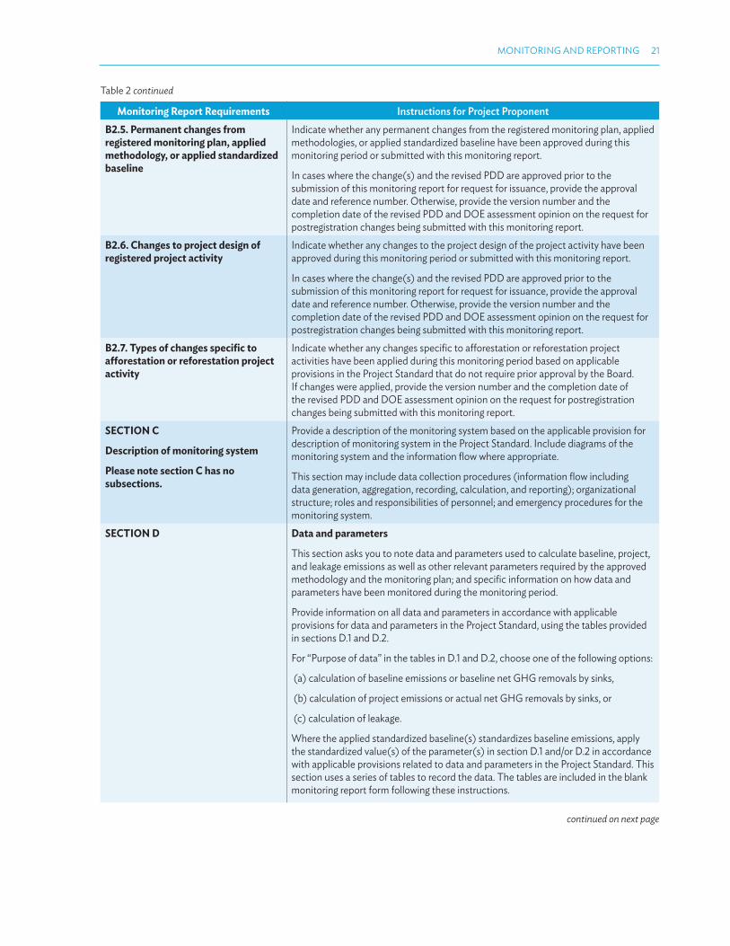
B2.5. Permanent changes from registered monitoring plan, applied methodology, or applied standardized baseline
Indicate whether any permanent changes from the registered monitoring plan, applied methodologies, or applied standardized baseline have been approved during this monitoring period or submitted with this monitoring report.
In cases where the change(s) and the revised PDD are approved prior to the submission of this monitoring report for request for issuance, provide the approval date and reference number. Otherwise, provide the version number and the completion date of the revised PDD and DOE assessment opinion on the request for postregistration changes being submitted with this monitoring report.
B2.6. Changes to project design of registered project activity
Indicate whether any changes to the project design of the project activity have been approved during this monitoring period or submitted with this monitoring report.
In cases where the change(s) and the revised PDD are approved prior to the submission of this monitoring report for request for issuance, provide the approval date and reference number. Otherwise, provide the version number and the completion date of the revised PDD and DOE assessment opinion on the request for postregistration changes being submitted with this monitoring report.
B2.7. Types of changes speciic to aforestation or reforestation project activity
Indicate whether any changes speciic to aforestation or reforestation project activities have been applied during this monitoring period based on applicable provisions in the Project Standard that do not require prior approval by the Board. If changes were applied, provide the version number and the completion date of the revised PDD and DOE assessment opinion on the request for postregistration changes being submitted with this monitoring report.
SECTION C
Description of monitoring system
Please note section C has no subsections.
Provide a description of the monitoring system based on the applicable provision for description of monitoring system in the Project Standard. Include diagrams of the monitoring system and the information low where appropriate.
This section may include data collection procedures (information low including data generation, aggregation, recording, calculation, and reporting); organizational structure; roles and responsibilities of personnel; and emergency procedures for the monitoring system.
SECTION D Data and parameters
This section asks you to note data and parameters used to calculate baseline, project, and leakage emissions as well as other relevant parameters required by the approved methodology and the monitoring plan; and speciic information on how data and parameters have been monitored during the monitoring period.
Provide information on all data and parameters in accordance with applicable provisions for data and parameters in the Project Standard, using the tables provided in sections D.1 and D.2.
For “Purpose of data” in the tables in D.1 and D.2, choose one of the following options:
(a) calculation of baseline emissions or baseline net GHG removals by sinks,
(b) calculation of project emissions or actual net GHG removals by sinks, or
(c) calculation of leakage.
Where the applied standardized baseline(s) standardizes baseline emissions, apply the standardized value(s) of the parameter(s) in section D.1 and/or D.2 in accordance with applicable provisions related to data and parameters in the Project Standard. This section uses a series of tables to record the data. The tables are included in the blank monitoring report form following these instructions.
continued on next page
Table 2 continued

22 MONITORING, REPORTING, AND VERIFICATION MANUAL FOR CLEAN DEVELOPMENT MECHANISM PROJECTS
Monitoring Report Requirements Instructions for Project Proponent
D1. Data and parameters ixed ex ante or at renewal of crediting period
Include data that are ixed before registration and/or at the renewal of crediting period and are used during this monitoring period under section D.1.
For “Value(s) applied,” use one table to report multiple values referring to the same data and parameter, if applicable. Use reference(s) to electronic spreadsheets, if necessary.
Use the following table, using a separate table for each piece of data and parameter.
(Copy this table for each piece of data and parameter)
Data/parameter:
Unit
Description
Source of data
Value(s) applied
Choice of data or measurement methods and procedures
Purpose of data
Additional comments
D2. Data and parameters monitored For “Monitoring equipment” in the table, provide information on type, accuracy class, serial number, calibration frequency, date of last calibration, and validity.
For “Value(s) of monitored parameter,” use one table to report multiple values referring to the same data and parameter, if applicable. Use reference(s) to electronic spreadsheets, if necessary.
Use the following table, using a separate table for each piece of data and parameter.
(Copy this table for each piece of data and parameter)
Data/parameter:
Unit
Description
Measured/calculated/default
Source of data
Value(s) of monitored parameter
Monitoring equipment
Measuring/reading/recording frequency
Calculation methods (if applicable)
QA/QC procedures:
Purpose of data
Additional comments
D3. Implementation of sampling plan If data and parameters monitored described in section D.2 above are determined by a sampling approach, provide a description on how project participants implemented the sampling eforts and surveys for those data and parameters according to the sampling plan. Include (a) description of implemented sampling design; (b) collected data (attach and provide reference to electronic spreadsheets, if
necessary); (c) analysis of the collected data; and (d) demonstration on whether the required conidence/precision has been met.
SECTION E Calculation of emission reductions or GHG removals by sinks
For the parameter global warming potentials, from 1 January 2013, include the values adopted by decision 4/CMP.7 to calculate the emission reductions achieved in the second commitment period of the Kyoto Protocol in accordance with the applicable provisions in the Project Standard.
For more information on 4/CMP.7 please refer to the following website: http://unfccc.int/meetings/durban_nov_2011/session/6250/php/view/decisions.php
continued on next page
Table 2 continued
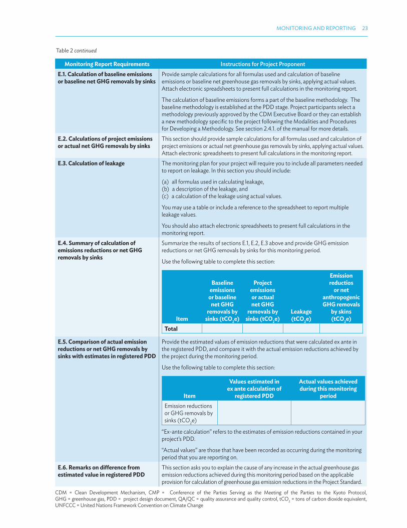
MONITORING AND REPORTING 23
Monitoring Report Requirements Instructions for Project Proponent
E.1. Calculation of baseline emissions or baseline net GHG removals by sinks
Provide sample calculations for all formulas used and calculation of baseline emissions or baseline net greenhouse gas removals by sinks, applying actual values. Attach electronic spreadsheets to present full calculations in the monitoring report.
The calculation of baseline emissions forms a part of the baseline methodology. The baseline methodology is established at the PDD stage. Project participants select a methodology previously approved by the CDM Executive Board or they can establish a new methodology speciic to the project following the Modalities and Procedures for Developing a Methodology. See section 2.4.1. of the manual for more details.
E.2. Calculations of project emissions or actual net GHG removals by sinks
This section should provide sample calculations for all formulas used and calculation of project emissions or actual net greenhouse gas removals by sinks, applying actual values. Attach electronic spreadsheets to present full calculations in the monitoring report.
E.3. Calculation of leakage The monitoring plan for your project will require you to include all parameters needed to report on leakage. In this section you should include:
(a) all formulas used in calculating leakage,(b) a description of the leakage, and (c) a calculation of the leakage using actual values.
You may use a table or include a reference to the spreadsheet to report multiple leakage values.
You should also attach electronic spreadsheets to present full calculations in the monitoring report.
E.4. Summary of calculation of emissions reductions or net GHG removals by sinks
Summarize the results of sections E.1, E.2, E.3 above and provide GHG emission reductions or net GHG removals by sinks for this monitoring period.
Use the following table to complete this section:
Item
Baseline emissions
or baseline net GHG
removals by sinks (tCO
2e)
Project emissions or actual net GHG
removals by sinks (tCO
2e)
Leakage (tCO
2e)
Emission reductios
or net anthropogenic GHG removals
by skins (tCO
2e)
Total
E.5. Comparison of actual emission reductions or net GHG removals by sinks with estimates in registered PDD
Provide the estimated values of emission reductions that were calculated ex ante in the registered PDD, and compare it with the actual emission reductions achieved by the project during the monitoring period.
Use the following table to complete this section:
Item
Values estimated in ex ante calculation of
registered PDD
Actual values achieved during this monitoring
period
Emission reductions or GHG removals by sinks (tCO
2e)
“Ex-ante calculation” refers to the estimates of emission reductions contained in your project’s PDD.
“Actual values” are those that have been recorded as occurring during the monitoring period that you are reporting on.
E.6. Remarks on diference from estimated value in registered PDD
This section asks you to explain the cause of any increase in the actual greenhouse gas emission reductions achieved during this monitoring period based on the applicable provision for calculation of greenhouse gas emission reductions in the Project Standard.
CDM = Clean Development Mechanism, CMP = Conference of the Parties Serving as the Meeting of the Parties to the Kyoto Protocol, GHG = greenhouse gas, PDD = project design document, QA/QC = quality assurance and quality control, tCO
2 = tons of carbon dioxide equivalent,
UNFCCC = United Nations Framework Convention on Climate Change
Table 2 continued

24 MONITORING, REPORTING, AND VERIFICATION MANUAL FOR CLEAN DEVELOPMENT MECHANISM PROJECTS
2.5 MANAGING REQUIRED CHANGES TO THE MONITORING PLAN
During the process of following the monitoring plan it may become apparent that changes or deviations are required. Changes are a common occurrence given that the PDD is most often prepared before the project has been built and/or commissioned. These are also postregistration changes (PRC).
The process for handling these changes is provided in the CDM Project Standard.21
Module 4: Postregistration Changes explains this process in more detail including procedural guidance. A summary of both changes and deviations is provided in this section in order to provide context for the discussion of the monitoring plan.
(i) Postregistration Changes: How to Request a Revision to the Monitoring Plan
A revision to the monitoring plan is classiied as a PRC. To make a revision to improve its accuracy and/or completeness of information in the monitoring plan, the project participant is required to justify the changes and submit a revised PDD (including revisions to the monitoring plan) to the DOE for validation.
If the changes occur at the veriication stage, the DOE is required to submit a request for approval to the Board. This request should include a revised monitoring plan and should be made prior to the submission of a request for issuance for the period being veriied. This means that the DOE cannot go ahead with completing the veriication and requesting issuance of CERs until the revised monitoring plan has been approved. Requesting revisions at the veriication stage can lead to long delays for the project.
To avoid these delays, the project participant can be proactive in trying to identify where the actual project (once built) difers from the monitoring plan that was written at the PDD stage.
Options for doing this include initial veriication of project activity (also known as preliminary veriication; see section 3.7) and conducting periodic internal audits to identify where corrective actions are required and to ensure that they are taken into account as soon as possible.
(ii) How to Request a Deviation for a Monitoring Period
In certain circumstances, the project participant may be temporarily unable to monitor CDM project activity in accordance with the approved monitoring plan or methodology. This happens, for example, if equipment breaks down and takes some time to be ixed or replaced.
If such a deviation occurs, the project participants are required to describe in the monitoring report the nature, extent, and duration of the nonconforming monitoring and the proposed alternative method for monitoring of project activity during the period. The alternative method will usually have to be justiied as being conservative.
21 UNFCCC. 2014. CDM Standards. http://cdm.unfccc.int/Reference/Standards/index.html

MONITORING AND REPORTING 25
2.6 MONITORING ISSUES
This section discusses common issues and concerns that may arise in the monitoring process. Understanding common issues will assist project participants to mitigate and resolve issues of their own. The issues discussed were drawn from the collective experience of practitioners who have completed the monitoring or veriication process.
2.6.1 Poorly Installed and Tagged Monitoring Equipment22
Monitoring equipment should be properly installed and tagged. This will allow maintenance personnel to easily identify the equipment that they must perform the required quality control checks on as per the registered PDD. The location of the equipment, e.g., the point at which the parameter is being monitored, must also be consistent with the monitoring plan in the PDD.
Access to the equipment should also be considered, especially for ongoing veriication. The veriier may want to physically verify the location of a meter and check the local display.
2.6.2 Selection of Monitoring Equipment
The selection of appropriate monitoring equipment and monitoring system plays an important part in the successful monitoring of a project.
When selecting equipment, the project participant has to consider many factors including the accuracy of the data that will be provided by the equipment, the cost of the equipment, whether a backup meter is required, the human resources available to undertake monitoring, as well as other practical issues.
Some speciic issues to consider when selecting equipment include the following:
(i) Frequency of Monitoring
That is, whether the monitoring is to be done on a continuous, intermittent, daily, weekly, monthly, or annual basis. This will help to determine whether it is most cost-efective to hire, lease, or buy the equipment. In certain cases it may be possible and more cost-efective to engage an accredited or approved laboratory to carry out periodic measurements, if this is all that is required. The required monitoring frequency should have been deined in the monitoring plan included in the PDD. If the frequency is not deined in the PDD, then it should follow the requirements of relevant national standards of the host country.
(ii) The Use of the Data and Risk Associated with It
Many of the parameters that are required to be measured as part of the monitoring plan are also required to be measured for other purposes. This will inluence the type of equipment selected, particularly if the parameter being measured relates to project revenue. For example, for a renewable energy project, two of the key CDM monitoring parameters are electricity generation and export. These same parameters will also be the key monitoring requirements under the power purchase agreement that determines the project’s revenue. Equipment will need to be of high accuracy and quality to minimize the risk of inaccurate or incorrect measurements, and the project participants will usually have strict monitoring
22 UNEP. 2011. CDM PDD Guidebook, Navigating the Pitfalls, Third Edition. http://cd4cdm.org/Publications/PDDguidebook_3rdEdition.pdf

26 MONITORING, REPORTING, AND VERIFICATION MANUAL FOR CLEAN DEVELOPMENT MECHANISM PROJECTS
requirements under the PPA to comply with. It is likely that the equipment would have been selected for compliance with the PPA, and will be used for the CDM as a secondary purpose. This is acceptable, provided that this was considered in the monitoring plan in the PDD.
(iii) Accuracy of the Measurement
The required accuracy of measurement is predeined in the monitoring plan (included in the PDD). It is critical that project participants select monitoring equipment that meets the requirements of the monitoring plan. The required accuracy of the measurement is usually a key determinant of the cost of the equipment. The accuracy of the equipment will determine the degree of accuracy to which emission reductions can be measured.
(iv) Equipment Technical Speciications
Specs include the range and whether the equipment is analog or digital. In most cases this will be deined in the monitoring plan. The project participants must select equipment appropriate for the parameter being measured, the speciic requirements of the project, and at an appropriate cost.
(v) Backup Meter
For critical parameters it is recommended that a backup meter be installed, in order to continue monitoring in the event that the main meter fails. Typically, the need for a backup meter would have been deined in the monitoring plan in the PDD as part of QA/QC procedures.
(vi) Availability of Calibration/Maintenance Facility within the Country
Project participants need to consider whether there is an appropriate calibration and/or maintenance facility including qualiied personnel in the country where the project is situated. The facility and personnel need to be qualiied to calibrate the particular type or brand of equipment. If facilities and personnel are not available, equipment will need to be sent overseas—this can be a costly and time-consuming option.
(vii) Specialized Training
Monitoring instruments are sophisticated and require specialized training in order to operate them efectively. Project participants should consider the capacity of local staf to undertake training and to subsequently operate monitoring instruments. If local capacity is insuicient, then the project may need to recruit international experts to assist.
(viii) Applicable Standards
Selection of standards is an important aspect of monitoring. Where possible, national standards should be selected, as the testing and compliance personnel and infrastructure will be more readily available. However, in the absence of such national standards, relevant international standards may be followed for selecting an instrument (e.g., the American Society of Mechanical Engineers [ASME], Australian, or British standards).
(ix) Use of Old Equipment
Many project owners prefer to use old monitoring equipment available to them from previous projects, or other sections of the plant, or equipment that was previously used as backup. Project owners typically do this due to cost considerations, particularly if the monitoring equipment is only used for CDM purposes and not for the day-to-day operations of the plant.
MONITORING AND REPORTING 27
If project owners do use old equipment, then it is important to irst check the availability of documentation, such as calibration records and speciications. If supporting documentation is not available, then using old monitoring equipment is not advised. Project participants should also consider i–vii above, as each of these issues also relates to old monitoring equipment.
2.6.3 Calibration of Equipment
The project participant is required to conduct calibration of the monitoring equipment at a frequency speciied in the monitoring methodology/monitoring plan.
What Is Calibration?
Calibration is a process that identiies the extent to which the value being recorded by a device deviates from the true value. Calibration ensures the accuracy of the measurement of the particular parameter.
Over time, an instrument’s performance may gradually deviate from the stated speciication. This can happen for a variety of reasons, such as
(i) mechanical wear and tear;
(ii) the efects of dust or fumes; or
(iii) chemical and operating environment.
Calibration overcomes this deviation and corrects the instrument so that it is giving readings correctly.
Calibration can be done in situ (with the instrument remaining in place) or the instrument can be removed and sent for full calibration at a laboratory or testing facility.
Typically, national standards or the manufacturer of the instrument will provide guidance on the required calibration frequency, and this should have been taken into account when designing the monitoring plan.
During veriication, the DOE will conirm whether the calibration frequency outlined in the monitoring plan has been followed. Therefore, even if the calibration frequencies outlined in the monitoring plan are more frequent than those required by regulation or the manufacturer, it is important that they are followed (see Example 1 on the following pages for further details).
Note that it is not always possible to access the meter for maintenance or calibration when the project is operational. In such cases it will be important to prioritize meter maintenance or calibration as part of planned preventative maintenance schedules and activities, or planned shutdowns.
Calibration should only be conducted by a qualiied technician in consultation with the manufacturer of the instrument.
Calibration Certiicates
The project participant should always obtain a calibration certiicate as evidence that the calibration has been performed. Key elements of the calibration certiicate include
(i) supplier’s contact details (person who performed the calibration);
(ii) unique tracking and/or certiicate number;
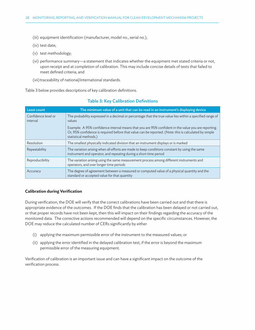
28 MONITORING, REPORTING, AND VERIFICATION MANUAL FOR CLEAN DEVELOPMENT MECHANISM PROJECTS
(iii) equipment identiication (manufacturer, model no., serial no.);
(iv) test date;
(v) test methodology;
(vi) performance summary—a statement that indicates whether the equipment met stated criteria or not, upon receipt and at completion of calibration. This may include concise details of tests that failed to meet deined criteria; and
(vii) traceability of national/international standards.
Table 3 below provides descriptions of key calibration deinitions.
Table 3: Key Calibration Deinitions
Least count The minimum value of a unit that can be read in an instrument’s displaying device
Conidence level or interval
The probability expressed in a decimal or percentage that the true value lies within a speciied range of values
Example: A 95% conidence interval means that you are 95% conident in the value you are reporting. Or, 95% conidence is required before that value can be reported. (Note: this is calculated by simple statistical methods.)
Resolution The smallest physically indicated division that an instrument displays or is marked
Repeatability The variation arising when all eforts are made to keep conditions constant by using the same instrument and operator, and repeating during a short time period
Reproducibility The variation arising using the same measurement process among diferent instruments and operators, and over longer time periods
Accuracy The degree of agreement between a measured or computed value of a physical quantity and the standard or accepted value for that quantity
Calibration during Veriication
During veriication, the DOE will verify that the correct calibrations have been carried out and that there is appropriate evidence of the outcomes. If the DOE inds that the calibration has been delayed or not carried out, or that proper records have not been kept, then this will impact on their indings regarding the accuracy of the monitored data. The corrective actions recommended will depend on the speciic circumstances. However, the DOE may reduce the calculated number of CERs signiicantly by either
(i) applying the maximum permissible error of the instrument to the measured values; or
(ii) applying the error identiied in the delayed calibration test, if the error is beyond the maximum permissible error of the measuring equipment.
Veriication of calibration is an important issue and can have a signiicant impact on the outcome of the veriication process.
MONITORING AND REPORTING 29
2.6.4 Ensuring the Quality of the Data Collected
To ensure the quality of the data collected is to a suicient level of accuracy, it is useful to consider the checklist of items the DOE will check during veriication (see module 3: Veriication for full details). Understanding the DOE’s role in the veriication process is critical to saving time and resources from incorrect or inaccurate monitoring.
A DOE undertaking data checks and calculations will use the instructions listed below. Please note these instructions aim to assist project participants to better understand the DOE’s role—these steps do not need to be undertaken by project participants themselves.
(i) Determine whether a complete set of data is available that covers the whole monitoring period. If only partial data is available, because some parameters have not been monitored in accordance with the registered monitoring plan, the DOE then opts to either make the most conservative assumption theoretically possible in inalizing the veriication report or raises a request for deviation prior to submitting a request for issuance.
(ii) Cross-check the information provided in the monitoring report against other sources, such as original data collection sheets, logbooks, inventories, purchase records, laboratory analysis, etc.
(iii) Conirm that the calculations have been carried out in accordance with the formulas and methods described in the monitoring plan and the applied methodology.
(iv) Conirm whether assumptions (if any) used in emission calculations have been justiied.
(v) Conirm whether emission factors, Intergovernmental Panel on Climate Change default values, and other reference values have been correctly applied.
Project participants in some cases record monitoring data in hard copy (e.g., logbooks) and subsequently transcribe the data to an electronic format, such as databases or data sheets. If project participants do transcribe data, care must be taken to ensure that the transcription process is accurate.
To manage this risk, the monitoring plan (in the PDD) should include a QA/QC procedure that checks the accuracy of the data transfer process. Internal audits can also be useful to identify errors ahead of external veriication. Even if these measures are not speciied in the PDD, it is recommended that they be put into place when the monitoring plan is implemented. The more accurate the data that is collected, the less likely that issues arise during veriication.
2.6.5 Standard Conditions and Unit Conversions
Two important issues to consider when ensuring accurate recording and measuring of emission reductions are (i) the conversion of data to standard conditions and (ii) the use of appropriate unit conversions.
Standard or normal conditions for temperature and pressure are widely employed as follows:
(i) Standard Conditions:
0°C (273.15°K) at 1.01325 bar (atmospheric pressure; 1 atm)
(ii) Normal Conditions:
15°C (288.15°K) at 1.01325 bar (atmospheric pressure; 1 atm)

30 MONITORING, REPORTING, AND VERIFICATION MANUAL FOR CLEAN DEVELOPMENT MECHANISM PROJECTS
The reporting condition (i.e., either Standard or Normal) should be selected at the beginning of the project and stated clearly throughout the PDD, as well as in the monitoring plan.
In addition, project participants should clearly deine the units of measurement for each parameter and take care to ensure that any unit conversions are done accurately. This is particularly important if the units that the parameter is measured in are diferent from the units used in reporting, as a conversion will have to be undertaken between the raw data and the data used in the monitoring report. Clear records of these conversions should be kept to allow the DOE to follow step by step from raw data through to the calculated CERs.
2.6.6 Record-keeping
Implementing a robust record-keeping system is an essential part of the monitoring plan.23 The record-keeping system should include all the CDM parameters that are required by the baseline and monitoring methodology applied in the PDD and are necessary for the inal calculations for the amount of greenhouse gas emissions that are reduced. Project participants may develop Excel-based templates or use customized software depending on the complexity and volume of data. Project participants should consider the most eicient way to manage record-keeping and data when designing the record-keeping systems.
Record-keeping is particularly important, as CDM projects have long time horizons—10 years if a ixed crediting period is chosen, or 7 years in the case of a renewable period (renewable up to two times, for a maximum total of 21 years). Data should be archived by the project participants both in electronic and paper format for the whole crediting period of the project plus an additional 2 years.
It is important that authorized and trained personnel carry out the record-keeping. A good record-keeping management system will include a clear delineation of duties between personnel and technical staf—this helps to ensure that responsibilities for the iling of instrumentation records are clear.
For each record, the type of data to be recorded should clearly include the following items of information for each dataset, instrument, and sensor:
(i) type of equipment, meter, sensor, instrument, etc. used;
(ii) data source (e.g., location points, time);
(iii) unit(s) the data is recorded in (e.g., megawatt hour, meter per second);
(iv) whether the data is measured, calculated, or estimated;
(v) recording frequency (e.g., continuous, hourly, monthly, weekly);
(vi) archiving technique (e.g., logbook, electronic); and
(vii) personnel recording the data.
Data management is also critical to the long-term success of a CDM project. Data management practices should be developed for both digital and hard copy recorded data.
In many cases the monitoring report will rely on data from multiple years and the source data will need to be eiciently located by the DOE for review during veriication. Locating source data is a common problem experienced during veriication. DOEs conducting veriication often spend substantial time ensuring that original data collection
23 UNEP. 2011. CDM PDD Guidebook, Navigating the Pitfalls, Third Edition. http://cd4cdm.org/Publications/PDDguidebook_3rdEdition.pdf

MONITORING AND REPORTING 31
input sheets and logbooks are thoroughly cross-checked with collated data provided in electronic form and reported in the monitoring report and calculation sheets.
Records should include monitoring records, and also other important evidence to support decisions made, such as photo documentation or estimation techniques.
2.6.7 Laboratory Testing
If testing by an independent or certiied laboratory is needed, then project participants must ensure that the speciications of the laboratory and their test methods meet those stipulated in the monitoring plan contained within the PDD. For example, the frequency of testing, qualiications of the lab, and testing parameters must meet the requirements set out in the monitoring plan.
2.6.8 Active Monitoring and Analyzing the Monitoring Data
It is important for project participants to actively monitor and analyze monitoring data, so that data issues can be discovered and corrected in a timely manner. Project participants should do this on an ongoing basis and should not wait until immediately before a veriication to look at monitoring data. Project participants have reported in the past the existence of data issues that went undiscovered for more than 2 years of operation.
2.6.9 Managing Monitoring Teams
In some cases, monitoring activities will be outsourced to an independent consultant. In these cases it is critical that project participants properly manage the consultants in order to ensure that monitoring takes place within the guidelines of the PDD. If monitoring is outsourced, project participants should still be aware of how monitoring is taking place and regularly receive updates on any potential issues and the data (and emissions reductions) being collected.
2.6.10 Monitoring of Sustainable Development Parameters (sustainable development tool)
The sustainable development tool (sustainable development tool) was developed to help project participants measure environmental, social, and economic parameters to determine or demonstrate the sustainability of the project activity. It is a voluntary tool that was approved by the CDM Executive Board. As a voluntary tool, it should be noted that the monitoring of sustainable development parameters is not a compulsory part of the monitoring, veriication, and issuance process.
However, many buyers will pay a premium for CERs from projects with environmental and/or social beneits. Using the sustainable development tool can help project participants demonstrate to potential buyers the contribution of the project to sustainable development by using a process that has been approved externally by the Executive Board.
The tool can be accessed from the CDM Tools web page.24 The major beneits of using this tool are as follows:
(i) The tool provides a structured, consistent, comparable, and robust manner of highlighting the sustainable development cobeneits of CDM projects and PoAs.
24 UNFCCC. 2014. Tools. http://cdm.unfccc.int/Reference/tools/index.html
32 MONITORING, REPORTING, AND VERIFICATION MANUAL FOR CLEAN DEVELOPMENT MECHANISM PROJECTS
(ii) The tool comprises a checklist of predeined criteria and indicators that help describe the impact of project activities and PoAs on the environment, society, and economy of the host country.
(iii) Project participants can use their published SDC description report to highlight and promote the sustainable development cobeneits of their project activities and PoAs.
(iv) SDC description reports will help buyers of CERs to easily identify projects with high sustainable development beneits.
Project participants may wish to view an example sustainable development report in order to better understand the requirements of using the sustainable development tool. A sample sustainable development report is included as Appendix 2.
33
3.1 INTRODUCTION TO MODULE
This module provides project participants with the information required to work efectively with the Designated Operational Entity (DOE) conducting the veriication process. The module contains the following subsections:
3.2 Deinition of Veriication
3.3 Timing of Veriication
3.4 How to Select and Work with a Designated Operational Entity
3.5 Designated Operational Entity Activities
3.6 Clariication Requests, Corrective Action Requests, and Forward Action Requests
3.7 Results of the Veriication and Requests for Issuance
3.8 Preliminary Veriication
3.2 DEFINITION OF VERIFICATION
The veriication process is a thorough, independent assessment of the registered Clean Development Mechanism (CDM) project after implementation to conirm that the reductions in greenhouse gas emissions claimed for a CDM project over a deined period of time (a veriication period) are true and correct.25
The project participant engages a DOE to verify the data that has been collected in accordance with the monitoring plan. That data will be set out in a monitoring report, which must be provided to the DOE engaged to conduct the veriication.
CDM veriication requirements are described in detail in the CDM validation and veriication manual (VVM). DOEs refer to the VVM as a guide to ensure that they achieve quality and consistency in their validation and veriication work. DOEs are also required to comply with the CDM VVS when conducting veriications.26
Activities undertaken by the DOE to determine compliance are outlined in full in section 3.4.
25 UNFCCC. 2005. Decision 3/CMP.1 Modalities and procedures for a clean development mechanism as deined in Article 12 of the Kyoto Protocol. https://cdm.unfccc.int/Reference/COPMOP/08a01.pdf#page=6
26 This standard is periodically updated and so project participants should check the UNFCC website for the latest version.
MODULE 3
VERIFICATION

34 MONITORING, REPORTING, AND VERIFICATION MANUAL FOR CLEAN DEVELOPMENT MECHANISM PROJECTS
3.3 TIMING OF VERIFICATION
The project participants can choose the time period of the irst veriication. The subsequent veriications and certiications can also be carried out at the intervals convenient to the project participants, until the end of the crediting period.
If an Emission Reduction Purchase Agreement (ERPA) exists for the sale of certiied emission reductions (CER), then this will often specify a delivery schedule for when CERs must be delivered to the buyer. This will in turn determine when the veriications have to occur so that the CERs have been issued in time to be delivered.
3.4 HOW TO SELECT AND WORK WITH A DESIGNATED OPERATIONAL ENTITY
DOE engagement is one of the most important tasks for the project participants. Timely engagement of the DOE and close coordination with them throughout the veriication process will help progress the project to the CER issuance stage.
DOEs are accredited by the CDM Executive Board upon recommendation from the accreditation panel. The DOEs are accredited according to their expertise (sectoral experience). The types of irms that are accredited as DOEs vary and can include accounting irms, accreditation/certiication irms, consulting irms, and law irms. Figure 8 outlines items to consider when selecting a DOE.
For large-scale projects the DOE performing the veriication must be diferent from the DOE that performed validation. However, the same DOE can conduct validation, veriication, and certiication for a small-scale CDM project activity or bundled small-scale CDM project activities.
Figure 8: Items to Consider When Selecting a Designated Operational Entity
DOE = designated operational entity, UNFCCC = United Nations Framework Convention on Climate Change.
Source: UNFCCC. 2014. What is the CDM. https://cdm.unfccc.int/about/index.html
• Review the DOE’s ability to complete the veriication by reviewing their speciic sectoral experience on the UNFCCC website: https://cdm.unfccc.int/DOE/list/index.html
• If possible ind out if past clients were satisied with their experience.
• Check for luency in the local language or country experience. Language skills are important, as the DOE will need to speak to team members (including site personnel) to verify information for data collection, equipment calibration, training, etc.
• Request information on the team composition in terms of internal and external experts. Internal experts are preferable to external experts, as they will be available and committed up to the completion of the job.
• Conirm the availability of the DOE resource persons (including for site visits) and their commitment to the timeline.
• Consider the proposed fee to be charged by the DOE. It is advisable in most circumstances to receive more than one quote to ensure they are competitive.

VERIFICATION 35
Project participants should consider how they intend to work with a DOE. Communicating openly and in a timely fashion will assist the DOE in completing the veriication process. Project participants can also help by ensuring that the DOE has timely access to information, records, personnel, and stakeholders that the DOE requires to complete veriication.
3.5 DESIGNATED OPERATIONAL ENTITY ACTIVITIES
The DOE needs to undertake a number of steps during a typical veriication process. It is important for a project participant to understand the steps taken by a DOE in order to work with them efectively. The time taken to complete veriication will vary for every project. Project participants can assist the process by being prepared in order to minimize the time taken.
The DOE will apply standard auditing techniques to assess the correctness of the information provided by the project participant including where appropriate but not limited to
(i) document review;
(ii) follow-up interviews with relevant stakeholders;
(iii) cross-check of information provided in the monitoring report and data from other sources such as plant logbooks, inventories, purchase records, or similar data sources; and
(iv) test of the correctness of critical formulas and calculations.
The DOE will typically follow these steps during veriication:
(i) Reviews and signs the contract, then appoints team members.
(ii) Conducts an opening meeting with project participants.
(iii) Receives a monitoring report from the project participants.
(iv) Publishes the monitoring report to make it publicly available 14 days prior to undertaking the site visit for the veriication.
(v) Reviews the monitoring report and provides the project participants with an information request outlining the documentation and information to be reviewed.
(vi) Conducts a desk review and cross-checks the information provided in the monitoring report. Conirms that the CER calculation is consistent with the registered PDD and applied methodologies.
(vii) Conducts an on-site visit.
(viii) Reviews monitoring results and veriies that the monitoring methodologies have been applied correctly and that documentation is complete and transparent.
(ix) Identiies and informs the project participants of any concerns relating to the conformity of the actual project activity and its operation with the registered PDD. Concerns are typically communicated in the form of corrective action request (CAR) and clariication request (CL). Project participants then must address the concerns and supply relevant additional information.
(x) Provides a draft veriication report to the project participants including formal indings (see subsection 3.6 for further details).
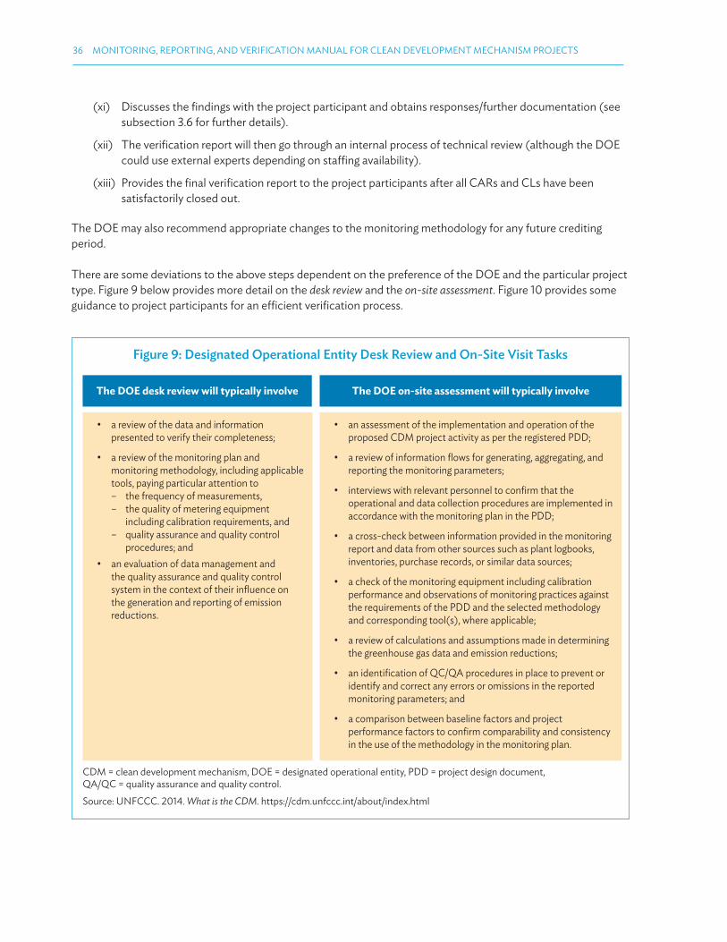
36 MONITORING, REPORTING, AND VERIFICATION MANUAL FOR CLEAN DEVELOPMENT MECHANISM PROJECTS
Figure 9: Designated Operational Entity Desk Review and On-Site Visit Tasks
The DOE desk review will typically involve The DOE on-site assessment will typically involve
• a review of the data and information presented to verify their completeness;
• a review of the monitoring plan and monitoring methodology, including applicable tools, paying particular attention to
– the frequency of measurements, – the quality of metering equipment
including calibration requirements, and – quality assurance and quality control
procedures; and
• an evaluation of data management and the quality assurance and quality control system in the context of their inluence on the generation and reporting of emission reductions.
• an assessment of the implementation and operation of the proposed CDM project activity as per the registered PDD;
• a review of information lows for generating, aggregating, and reporting the monitoring parameters;
• interviews with relevant personnel to conirm that the operational and data collection procedures are implemented in accordance with the monitoring plan in the PDD;
• a cross-check between information provided in the monitoring report and data from other sources such as plant logbooks, inventories, purchase records, or similar data sources;
• a check of the monitoring equipment including calibration performance and observations of monitoring practices against the requirements of the PDD and the selected methodology and corresponding tool(s), where applicable;
• a review of calculations and assumptions made in determining the greenhouse gas data and emission reductions;
• an identiication of QC/QA procedures in place to prevent or identify and correct any errors or omissions in the reported monitoring parameters; and
• a comparison between baseline factors and project performance factors to conirm comparability and consistency in the use of the methodology in the monitoring plan.
CDM = clean development mechanism, DOE = designated operational entity, PDD = project design document, QA/QC = quality assurance and quality control.
Source: UNFCCC. 2014. What is the CDM. https://cdm.unfccc.int/about/index.html
(xi) Discusses the indings with the project participant and obtains responses/further documentation (see subsection 3.6 for further details).
(xii) The veriication report will then go through an internal process of technical review (although the DOE could use external experts depending on staing availability).
(xiii) Provides the inal veriication report to the project participants after all CARs and CLs have been satisfactorily closed out.
The DOE may also recommend appropriate changes to the monitoring methodology for any future crediting period.
There are some deviations to the above steps dependent on the preference of the DOE and the particular project type. Figure 9 below provides more detail on the desk review and the on-site assessment. Figure 10 provides some guidance to project participants for an eicient veriication process.
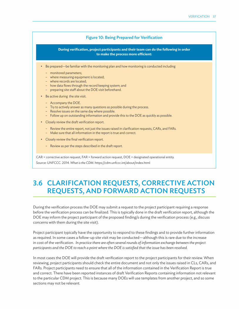
VERIFICATION 37
3.6 CLARIFICATION REQUESTS, CORRECTIVE ACTION REQUESTS, AND FORWARD ACTION REQUESTS
During the veriication process the DOE may submit a request to the project participant requiring a response before the veriication process can be inalized. This is typically done in the draft veriication report, although the DOE may inform the project participant of the proposed inding/s during the veriication process (e.g., discuss concerns with them during the site visit).
Project participant typically have the opportunity to respond to these indings and to provide further information as required. In some cases a follow-up site visit may be conducted—although this is rare due to the increase in cost of the veriication. In practice there are often several rounds of information exchange between the project participants and the DOE to reach a point where the DOE is satisied that the issue has been resolved.
In most cases the DOE will provide the draft veriication report to the project participants for their review. When reviewing, project participants should check the entire document and not only the issues raised in CLs, CARs, and FARs. Project participants need to ensure that all of the information contained in the Veriication Report is true and correct. There have been reported instances of draft Veriication Reports containing information not relevant to the particular CDM project. This is because many DOEs will use templates from another project, and so some sections may not be relevant.
Figure 10: Being Prepared for Veriication
During veriication, project participants and their team can do the following in order
to make the process more eicient:
• Be prepared—be familiar with the monitoring plan and how monitoring is conducted including
– monitored parameters; – where measuring equipment is located; – where records are located; – how data lows through the record keeping system; and – preparing site staf about the DOE visit beforehand.
• Be active during the site visit.
– Accompany the DOE. – Try to actively answer as many questions as possible during the process. – Resolve issues on the same day where possible. – Follow up on outstanding information and provide this to the DOE as quickly as possible.
• Closely review the draft veriication report.
– Review the entire report, not just the issues raised in clariication requests, CARs, and FARs. – Make sure that all information in the report is true and correct.
• Closely review the inal veriication report.
– Review as per the steps described in the draft report.
CAR = corrective action request, FAR = forward action request, DOE = designated operational entity.
Source: UNFCCC. 2014. What is the CDM. https://cdm.unfccc.int/about/index.html
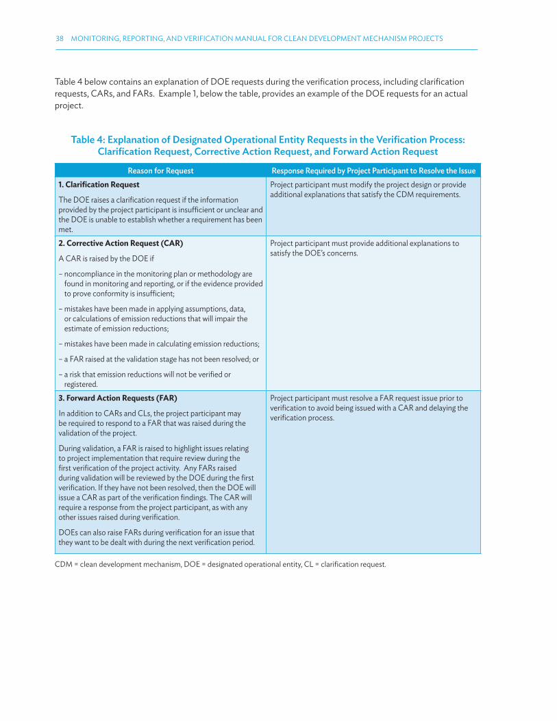
38 MONITORING, REPORTING, AND VERIFICATION MANUAL FOR CLEAN DEVELOPMENT MECHANISM PROJECTS
Table 4 below contains an explanation of DOE requests during the veriication process, including clariication requests, CARs, and FARs. Example 1, below the table, provides an example of the DOE requests for an actual project.
Table 4: Explanation of Designated Operational Entity Requests in the Veriication Process: Clariication Request, Corrective Action Request, and Forward Action Request
Reason for Request Response Required by Project Participant to Resolve the Issue
1. Clariication Request
The DOE raises a clariication request if the information provided by the project participant is insuicient or unclear and the DOE is unable to establish whether a requirement has been met.
Project participant must modify the project design or provide additional explanations that satisfy the CDM requirements.
2. Corrective Action Request (CAR)
A CAR is raised by the DOE if
– noncompliance in the monitoring plan or methodology are found in monitoring and reporting, or if the evidence provided to prove conformity is insuicient;
– mistakes have been made in applying assumptions, data, or calculations of emission reductions that will impair the estimate of emission reductions;
– mistakes have been made in calculating emission reductions;
– a FAR raised at the validation stage has not been resolved; or
– a risk that emission reductions will not be veriied or registered.
Project participant must provide additional explanations to satisfy the DOE’s concerns.
3. Forward Action Requests (FAR)
In addition to CARs and CLs, the project participant may be required to respond to a FAR that was raised during the validation of the project.
During validation, a FAR is raised to highlight issues relating to project implementation that require review during the irst veriication of the project activity. Any FARs raised during validation will be reviewed by the DOE during the irst veriication. If they have not been resolved, then the DOE will issue a CAR as part of the veriication indings. The CAR will require a response from the project participant, as with any other issues raised during veriication.
DOEs can also raise FARs during veriication for an issue that they want to be dealt with during the next veriication period.
Project participant must resolve a FAR request issue prior to veriication to avoid being issued with a CAR and delaying the veriication process.
CDM = clean development mechanism, DOE = designated operational entity, CL = clariication request.
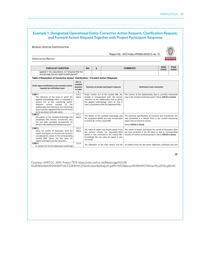
VERIFICATION 39
Example 1: Designated Operational Entity Corrective Action Request, Clariication Request, and Forward Action Request Together with Project Participant Response
BUREAU VERITAS CERTIFICATION
Report No: BVC/India-VR/658.49/2015 rev. 01
VERIFICATION REPORT
38
CHECKLIST QUESTION Ref. § COMMENTS Draft Concl
Final Concl
applied in the calculations, is it ensured that the annual caps are pro-rated to each period?
Table 2 Resolution of Corrective Action /Clarification / Forward Action Requests
D aft epo t la ifi atio s a d o e tive a tio e uests y ve ifi atio tea
Ref. to he klist uestio
i ta le
Su a y of p oje t pa ti ipa t espo se Ve ifi atio tea o lusio
CAR 1 The efe e e of the tools to hi h the applied ethodolog efe s is i di ated i se tio A. of the o ito i g epo t. Ho e e e sio u e of the additio alit tool efe ed i the o ito i g epo t a d the egiste ed PDD a e ot fou d
to e o siste t ith ea h othe .
A. . a o e
U de se tio A. of the e ised M‘, the ha ge is i o po ated ith the o e t efe e e of the additio alit tool to hi h
the applied ethodolog efe s to. This is o i o siste e ith the egiste ed PDD.
The e sio of the Additio alit Tool is o e tl e tio ed o i the e ised o ito i g epo t. He e CAR is losed.
CAR 2 Des iptio of the i stalled te h olog a d e uip e t like i e to , t a sfo e , et has ot ee p o ided t a spa e tl i detail i the e hosted o ito i g epo t.
B. . a o e The details of the i stalled te h olog a d
the e uip e t details a e o i o po ated i se tio B. of the e ised M‘.
The te h i al spe ifi atio s of I e to s a d T a sfo e a e o p ese ted i a ta ula fo i the e ised o ito i g epo t a d a e fou d to o e t.
He e CAR is losed.
CAR 3 Value fo o th of De e e fo I po t a d E po t a e fou d to e i o e t o side i g the alues i the o espo di g o ths JM‘. He e the Net alue fo
I po t a d E po t a e also i o e t.
D. . a o e The alue of e po t a d i po t po e f o
the p oje t a ti it fo De e e - o th is o o e ted i the e ised M‘.
A o di gl the et alue of e po t is also o e ted.
The alues of I po t a d E po t fo o th of De e e a e o o e ted i the E‘ sheet as ell as o espo di g se tio s of e ised o ito i g epo t. He e CAR is losed.
CAR 4 I se tio D. of the e hosted o ito i g
D. . The ali atio of the ai ete s a d the As e ide t f o the last ete ali atio e tifi ate that as
Courtesy. UNFCCC. 2014. Project 7373. https://cdm.unfccc.int/ilestorage/N/U/B/NUB78GI46A9XDW05FYJ3LTZ2KRHVC1/Veriication%20report.pdf?t=WDJ8bzczcWI3fDAPt77M7aoYfLsZD3Lq3DvW

40 MONITORING, REPORTING, AND VERIFICATION MANUAL FOR CLEAN DEVELOPMENT MECHANISM PROJECTS
BUREAU VERITAS CERTIFICATION
Report No: BVC/India-VR/658.49/2015 rev. 01
VERIFICATION REPORT
39
D aft epo t la ifi atio s a d o e tive a tio e uests y ve ifi atio tea
Ref. to he klist uestio
i ta le
Su a y of p oje t pa ti ipa t espo se Ve ifi atio tea o lusio
epo t, detail des iptio of the o ito i g e uip e t e e g ete i ludi g details of a u a lass, t pe & ake a e p o ided. The f e ue of ali atio is e tio ed as o e i ea s. The p e ious date of ali atio is p o ided. Ho e e alidit of
the sa e is ot p o ided. Fu the , if ali atio f e ue is to e o side ed
o e i ea s as pe the egiste ed PDD, the as pe the last date of ali atio
e tio ed, the ea s of alidit is o e a d the ali atio of ete s is due. P oje t pa ti ipa t to la if o this. The suppo ti g ali atio e tifi ate is also ot fou d to e
p o ided to the e ifi atio tea .
a o e he k ete s e e do e o / / a d / / espe ti el . The ali atio
e tifi ated of the sa e a e o su itted to the e ifi atio tea . Fu the the alidit is also i luded i the e ised M‘.
U de the u e t o ito i g pe iod, the e is a ali atio dela f o / / to
/ / fo the ai . Adopti g a o se ati e app oa h, the adjust e t has ee ade fo the a i u pe issi le
e o fo the hole o th of De e e -. Detailed al ulatio gi e i the e el
sp ead sheet.
do e o / / , the e t ali atio as e pe ted to e o du ted o / / . Ho e e it as fou d that the e as o ali atio do e fo the e e g ete s du i g the
u e t o ito i g pe iod. He e i li e ith EB A e , P oje t pa ti ipa t has applied a i u e o of . % o the
ete ed eadi gs fo e ti e o th of De e e i stead of just da s he the ete as ot u de alidit of ali atio . Appli atio of e o of . % is e ui ale t to the
e e g ete s a u a lass. The latest Cali atio took pla e o / / hi h o fi s that ete s e e ope ati g
o al a d o e o e o d its pe issi le li it as o se ed. This as o fi ed f o MOM dated / / sig ed Offi ials of GETCO, PGVCL a d TP‘EL ho it essed the ali atio p o ess. Thus app oa h follo ed P oje t
pa ti ipa t ill lead to o se ati e al ulatio of CE‘s. He e fou d a epta le a d the efo e CAR is losed.
CL A tual GHG E‘s a e o se ed to e o e tha the egiste ed PDD esti ates. Ho e e the justifi atio p o ided is ot fou d to e suffi ie tl justif i g the ase.
E. . a o e
The a tual GHG E‘ a hie ed u de the u e t o ito i g pe iod is , tCO e, hi h is . % o e tha the esti ated E‘ i
the egiste ed PDD. This o espo ds to a i ease i PLF % a hie ed the p oje t a ti it .
The PP ould like to get to the oti e of the e ifi atio tea that the highe PLF
a hie ed i the u e t o ito i g pe iod is ai l e ause of the highe sola i adia e
As o pa ed to the esti ated alue of E issio ‘edu tio , du i g u e t e ifi atio pe iod of / / - / / , the e as app o i atel . % highe e issio edu tio s a hie ed. To suppo t the sa e the do u e ta e ide es
e e su itted the P oje t pa ti ipa t a d it i ludes “ola ‘esou e Assess e t a d E e g ield Esti atio of MWp “ola Po e Pla t i Mithapu , Ja aga dist i t, Guja at dated “epte e , Dail “ola I adia e Data f o Ja ua – De e e a d a al sis ased o this data. F o the a al sis of data it as o se ed that du i g u e t
BUREAU VERITAS CERTIFICATION
Report No: BVC/India-VR/658.49/2015 rev. 01
VERIFICATION REPORT
40
D aft epo t la ifi atio s a d o e tive a tio e uests y ve ifi atio tea
Ref. to he klist uestio
i ta le
Su a y of p oje t pa ti ipa t espo se Ve ifi atio tea o lusio
e ei ed at the p oje t site. The PP ould like to p ese t the o thl i adia e data hi h is e ei ed at the site fo the u e t
o ito i g pe iod a e age . kWh/ /da a d o pa e this ith the ea s Meteo o data a e age . kWh/ /da used du i g the sola esou e assess e t of the site a thi d pa t at the ti e of p oje t de isio aki g. The sola i adia e a hie ed du i g the u e t o ito i g pe iod is % highe tha the Meteo o data. This lea l sho s that the highe PLF is
e ause of the highe i solatio e ei ed at the site. The i ease i sola i adia e is pu el e ause of seaso al a iatio s i
eathe o ditio s a d is o pletel e o d the o t ol of the PP.
Fu the the PP had adopted so e good ope atio al a d ai te a e p a ti e su h as f e ue t ate lea i g of the pa els o e i a o th a d seaso al tilt of the
sola pa els th i e i the ea hi h ight ha e o t i uted to highe ge e atio .
e ifi atio pe iod the sola i adia e i ide t o sola ells as o e as o pa ed to the sola i adia e that ould ha e
i ide t o the sola ell as esti ated i PLF epo t. As e ide t f o the ta le elo
Mo ths
Esti ated I adia e
ased o Meteo o
- i
kW/ pe da
A tual I adia e i
kW/ pe da
Pe e tage diffe e e
et ee esti ated a d a tual
Ja . . . . % % Fe . . . % % Ma . . . % % Ap . . . -6% % Ma . . . -8% - % Ju . . . - % % Jul . . . - 8% %
Aug . . . % % “ep . . . - % % O t . . . % % No . . . % % De . . . % %
The i adia e e ei ed du i g u e t o ito i g pe iod is al ost % o e tha the esti ated alue. This has e efited

VERIFICATION 41
BUREAU VERITAS CERTIFICATION
Report No: BVC/India-VR/658.49/2015 rev. 01
VERIFICATION REPORT
41
D aft epo t la ifi atio s a d o e tive a tio e uests y ve ifi atio tea
Ref. to he klist uestio
i ta le
Su a y of p oje t pa ti ipa t espo se Ve ifi atio tea o lusio
the p oje t a ti it to ge e ate highe ele t i it . F o the a o e ta le, it a e o se ed that du i g o ths of Ap il –Jul a d “ept a d Ma , the i adia e e ei ed the p oje t a ti it is less tha the esti ated figu e. Also, u like a o e tio al fuel like oal, sola i adia e patte a d/o a aila ilit is ot i o t ol of the P oje t pa ti ipa t o fo eseea le o a a ual asis. Keepi g the a o e i ie , a d i light of the fa t that ge e atio has ee oth lo e a d highe i p e ious ea s o pa ed to fo e ast, the ge e atio fo a d a ot e assu ed to e a pe a e t i ease ea o ea goi g fo a d. The highe e issio edu tio a hie ed du i g u e t e ifi atio pe iod is o l
due to easo s e o d the o t ol of the P oje t pa ti ipa t. Ve ifi atio tea as also assessed the fi a ial additio alit o side i g the u e t PLF that is ee a hie ed the p oje t
a ti it . The I‘‘ is ossi g the e h a k alue at the u e t PLF. Fu the e ifi atio tea also efe ed se tio des i i g se siti it a al sis, i the alidatio epo t hi h efe s to epo t o Pe fo a e of G id “ola PV Po e Pla ts u de
De o st atio P og a e pu lished Mi ist of Ne a d ‘e e a le e e g , Go e e t of I dia. The epo t gi es PLF a hie ed the ope atio of “ola PV pla ts i I dia to e i the a ge of . % - . %, hi h is ased o the a tual ope atio of “ola PV p oje ts. Also GE‘C Ta iff o de a aila le fo P oje t pa ti ipa t at the ti e of egist atio also e o e ded PLF of % i Guja at egio fo “ola PV.

42 MONITORING, REPORTING, AND VERIFICATION MANUAL FOR CLEAN DEVELOPMENT MECHANISM PROJECTS
3.7 RESULTS OF THE VERIFICATION AND REQUEST FOR ISSUANCE
After completing the veriication, the DOE will produce a inal veriication report. The veriication report briely documents the veriication process, methodology, and results.
Most project participants will also engage the same DOE to complete the CER Certiication Report at the end of the veriication (usually considered part of one engagement). Certiication is the formal conirmation by the DOE that the emission reductions set out in the veriication report were actually achieved. The key elements of certiication are as follows:
(i) It is a written assurance.
(ii) It conirms that a project activity achieved reductions in greenhouse gas emissions during a speciic period (the veriication period preceding).
(iii) It is performed by a DOE.
The veriication statement27 serves as the basis for the Executive Board to issue an equivalent amount of CERs.
Similar to the draft veriication report, project participants should review the inal veriication report carefully—not only the issues raised in CLs, CARs, and FARs.
After the project participant is satisied with the report, they will approve it. The DOE will then submit the report to the CDM Executive Board for issuance of CERs.
In cases where the project participant disagrees with the DOE’s inal veriication indings, there is a formal procedure for handling disputes.
PRELIMINARY VERIFICATION
Preliminary veriication, or “initial veriication” as it is commonly termed, is not to be confused as being part of the veriication process.
Preliminary veriication is a voluntary measure undertaken by project participants usually before the project has commenced. However, in some cases it can take place after the project has begun.
Preliminary veriication is generally conducted to ensure the project is implemented and operated according to the procedures set out in the PDD. A DOE is engaged to verify the validity of a project’s chosen methodologies—that is, if the project uses its baseline methodology, monitoring methodology, and monitoring plan, will the project be able to generate and monitor emission reductions as stated in the PDD?
Preliminary veriication provides reassurance that problems are not left unresolved until the veriication process, by which time they are more diicult to ix.
27 The veriication statement includes the scope of the veriication; the period of the veriication; and conclusions of the veriication, including the veriied amount of emission reductions for a given period and a liability statement with regards to the accuracy of the veriication statement.

43
4.1 INTRODUCTION TO MODULE
Changes to project design and/or project management are inevitable and in many circumstances this requires a change to the Clean Development Mechanism (CDM) documentation and/or procedures for the project. The CDM Project Standard provides guidance for managing changes, and this module explains this guidance in a clear and digestible format.
Module 4 contains the following subsections:
4.2 Classiication of Project Changes Under the Clean Development Mechanism
4.3 When to Notify the Executive Board of Temporary or Permanent Changes
4.4 Procedure for Obtaining Approval for Temporary and Permanent changes
4.2 CLASSIFICATION OF PROJECT CHANGES UNDER THE CLEAN DEVELOPMENT MECHANISM
There are many circumstances that lead to the need to make changes to CDM project documentation after registration. These changes need to be managed using the PRC process.
The CDM classiies changes into two categories: changes that are commercial (related to the management of the project) and changes that are temporary and permanent (related to the design of the project).
Commercial ChangesA commercial change to the project relates to changes in the oicial dealings of the project. These include things such as
(i) change of modalities of communication (MOC),
(ii) adding a project participant,
(iii) change in focal point,
(iv) voluntary withdrawal of project participant, and
(v) changes in contact details or procedures related to forwarding of CERs or voluntary cancellation of CERs.
MODULE 4
POSTREGISTRATION CHANGES

44 MONITORING, REPORTING, AND VERIFICATION MANUAL FOR CLEAN DEVELOPMENT MECHANISM PROJECTS
Guidance on how to apply for a commercial change is provided on the UNFCC website and is relatively less complex than design changes.28 Changes require the project participants, through their designated focal point(s), to
(i) complete and sign an MOC Statement Form (CDM-MOC-FORM);29 and
(ii) submit this form through the UNFCC website: https://cdm.unfccc.int/ModalitiesOfCommunication
Note that in order to add a project participant, a letter of approval (LOA) from the designated national authority that authorizes the participation of the new entity should be submitted together with the CDM-MOC-FORM. Speciic guidance and procedural tips for the other types of changes are outlined on the website page.30
For example, the guidance on how to add a project participant is as follows:
4.2.1 Temporary and Permanent Changes
The more complex type of changes are changes to the project design. Changes may arise because the CDM project has been implemented with a project design diferent from the project design described in the project design document (PDD), or the project design may be altered during the project’s lifetime. Both are common, as the PDD is often prepared before project construction has commenced, and some changes are beyond the control of the project participants.
28 UNFCCC. 2014. CDM Registry Commercial Changes Guidance. http://cdm.unfccc.int/Registry/guidance29 UNFCCC. 2014. MOC Statement Form CDM-MOC-FORM. http://cdm.unfccc.int/Registry/guidance30 UNFCCC. 2014. CDM Registry Commercial Changes Guidance. http://cdm.unfccc.int/Registry/guidance
Add a project participant
The following documents are required to add a new entity as a project participant:
• A Letter of Approval (LOA) from the DNA of a Party to the Kyoto Protocol, which authorizes the participation of the new entity.
• If the addition is not associated with changes in the nomination of focal point entity(ies), Annex 2, Sections 1 and 2 of the CDM-MOC-FORM only is required.
• If the addition does entail changes to the nomination of focal point entity(ies), a new CDM-MOC-FORM together with Annex 2, Sections 1 and 2 is required.
The above documents should be duly signed by the authorized signatory of the project participant(s) concerned and the
nominated focal point in accordance with the current Modalities of Communication (MOC).
All documents should be submitted through the link to the electronic interface.
The same procedure applies when an entity that is already a registered project participant would like to become a project
participant under a diferent Annex I Party.
Changes to CDM-MOC-FORM and related Annex 2 documentation should be signed by the designated focal point only
after a project participant(s) has signed on the respective form, this action being to ensure that the focal point veriies
and conirms any requested action from the project participant concerned prior to sending to CDM Registry for action.
Any documentation received by the CDM Registry which is not dated sequentially correct will be rejected.

POSTREGISTRATION CHANGES 45
Examples of the types of changes that could arise include
(i) changes in the efective output capacity,
(ii) the addition or removal of a component or extension of technology,
(iii) the removal or addition of one site (or more) of a project activity registered with multiple sites, or
(iv) changes to electricity export arrangements.
The changes that are made could be temporary or permanent changes, and hence these are the two subtypes of design changes under the CDM. Procedures for managing temporary or permanent changes are outlined in Section 4.4.
4.3 WHEN TO NOTIFY THE EXECUTIVE BOARD OF TEMPORARY OR PERMANENT CHANGES
The CDM Executive Board has speciied whether they must be notiied of design changes or not, dependent on the type of change made to the project. Table 5 below details changes (both permanent and temporary) to the project design that do not require the project participants or the DOE to notify the Executive Board. Table 6 details changes (both permanent and temporary) to the project design that do require the project participant or the Designated Operational Entity (DOE) to notify the Executive Board. The procedure for notifying the Executive Board can found in section 4.4.
Table 5: Postregistration Changes That DO NOT Require Notifying the Executive Board
Change that Has Occurred When the Executive Board Does Not Require Notiication
Corrections If it does not afect the design of the project (e.g., typographic error, location, name)
Temporary deviations from the registered monitoring plan, applied methodology, or applied standardized baseline
If project participant has temporarily not monitored parameters related to baseline GHG emissions or is unable to produce evidence and reports these parameters as zero
If project participant has temporarily not monitored parameters related to emissions or is unable to produce evidence and estimates the source of the GHG operated at maximum capacity for the full period of missing data
(Note: for consumption of electricity, add 10% to the estimate to account for transmission and distribution losses)
Permanent changes in the monitoring plan or applied methodology
If the monitoring equipment installed has a lower accuracy level than stipulated in the methodology
In the case of changes in the calibration frequency, accuracy/type/model of meter(s)
Location of meter(s)
Changes to project design If they do not adversely impact the additionality or project scale
GHG = greenhouse gas.

46 MONITORING, REPORTING, AND VERIFICATION MANUAL FOR CLEAN DEVELOPMENT MECHANISM PROJECTS
Table 6 below details changes (both permanent and temporary) to the project design that require the project participants or the DOE to notify the Executive Board. Two projects have also been used as examples for each type of change, as per the last column. The links for the projects are provided under the table. In addition, the links to the DOE’s report for assessing the postregistration changes are also provided. The details of the reason for the PRC and the DOE’s review of the PRC justiication are contained in the Assessment Opinion.
The procedure for notifying the Executive Board can found in section 4.4.
Table 6: Postregistration Changes that DO Require Notifying the Executive Board
Change that Has OccurredWhen the Executive Board
Requires Notiication Action to Take Example
Corrections If the change afects the project design, e.g., information or parameters ixed at validation as described in the registered PDD
Project participants must document these corrections in a revised PDD;
inform the DOE contracted to perform a veriication regarding the corrections; and
request any DOE at any time prior to the commencement of veriication to assess the corrections.
Zhejiang Tangcun 32MW Hydropower Project
See page 13 of the Assessment Opinion
Temporary deviations from the registered monitoring plan, applied methodology, or applied standardized baseline
If project participant has temporarily not monitored parameters related to baseline greenhouse gas emissions or is unable to produce evidence and the report does not list the relevant parameters as zero
Inform the DOE contracted to perform a veriication for the monitoring period during which they were unable to monitor the project in accordance with the registered monitoring plan, the applied methodology, or the applied standardized baseline; or
request any DOE at any time prior to the commencement of veriication of a monitoring period to assess the proposed alternative monitoring of the project.
Zhejiang Tangcun 32MW Hydropower Project
See pages 13–14 of the Assessment Opinion
continued on next page

POSTREGISTRATION CHANGES 47
Change that Has OccurredWhen the Executive Board
Requires Notiication Action to Take Example
Changes to the start date of the crediting period
If the start date of the crediting period was prior to the date of registration or more than 2 years ago, or more than 4 years ago for project activities hosted by a least developed country.
Project participants or DOE may not request any changes
Bringing forward the start date up to 1 year earlier than the date indicated in the registered PDD
Project participants or DOE to notify the secretariat of the changes (not required to notify the Executive Board)
Postponing the start date by up to 1 year, or by up to 2 years for project activities hosted by a least developed country
Project participants or DOE to notify the secretariat of the changes (not required to notify the Executive Board)
A change between 1 and 2 years, or between 2 and 4 years for project activities hosted by a least developed country
Project participants or DOE must demonstrate that no changes have occurred that would result in a less conservative baseline, and that substantive progress has been made to start the project; and
submit this demonstration to a DOE for assessment prior to making a request for approval by the Board in accordance with the CDM project cycle procedure.
Dagachhu Hydropower Project
See page 9 of the Assessment Opinion
Permanent changes to the registered monitoring plan, applied methodology, or applied standardized baseline
If the project participant is unable to implement the registered monitoring plan and it will not be possible to monitor the registered CDM project activity in accordance with a monitoring plan
Project participants or DOE describe the nature and extent of the nonconforming monitoring in a revised PDD
Zhejiang Tangcun 32MW Hydropower Project
See page 13 of the Assessment Opinion.
continued on next page
Table 6 continued

48 MONITORING, REPORTING, AND VERIFICATION MANUAL FOR CLEAN DEVELOPMENT MECHANISM PROJECTS
Change that Has OccurredWhen the Executive Board
Requires Notiication Action to Take Example
Changes to the project design Changes may include but may not be limited to changes in the efective output capacity, the addition of a component or extension of technology, the removal or addition of one site (or more) of a project activity registered with multiple sites
Project participants or DOE to prepare a revised PDD with the impacts of the proposed or actual changes to the registered PDD:
the additionality of the project—please note that this is a critical step;
the applicability and application of the applied methodology and, where applicable, the applied standardized baseline under which the project has been registered;
compliance of the monitoring plan with the applied methodology and, where applicable, the applied standardized baseline;
the level of accuracy and completeness in the monitoring of the project; and
the scale of the project activity.
Dagachhu Hydropower Project
See page 10 of the Assessment Opinion.
CDM = Clean Development Mechanism, DOE = designated operational entity, GHG = greenhouse gas, MW = megawatt, PDD = project design document.
Notes:
(i) Project documentation relating to postregistration changes for Zhejiang Tangcun 32MW Hydropower Project, People’s Republic of China can be accessed here: https://cdm.unfccc.int/PRCContainer/DB/prcp918857958/view
(ii) Project documentation relating to postregistration changes for Dagachhu Hydropower Project, Bhutan can be accessed here: https://cdm.unfccc.int/PRCContainer/DB/prcp790936211/view
Readers may also visit the relevant section of the CDM website in order to access further information about each of the examples, including project documentation.31
31 Information in this section has been drawn from publicly available information about both the Zhejiang Tangcun Hydropower Project and the Dagachhu Hydropower Project. Readers can access this information online using the links available above.
Table 6 continued

POSTREGISTRATION CHANGES 49
4.4 PROCEDURE FOR OBTAINING APPROVAL FOR TEMPORARY AND PERMANENT CHANGES
To obtain approval from the Executive Board for changes (as per Table 6 above), the DOE is required to submit a Postregistration Changes Request Form32 together with supporting documents. Submission requirements and procedural steps are detailed in the list below:
(i) Submission Requirements
(a) Project participant completes a Postregistration Changes Request Form.33
(b) An assessment opinion on the changes is given by the DOE.34
(c) A revised PDD is completed and provided (in both clean and track-change versions). (d) Any supplemental documentation supporting the revisions is attached. (e) Documentation is submitted to the Executive Board.
(ii) Procedural Steps
(a) completeness check as per the Postregistration Completeness Checklist;(b) Secretariat assessment stage of 14 days; (c) if required, clariication request with 14 days to reply;(d) if required, seeking inputs from the relevant panel/working group;(e) if required, inalization of secretariat assessment stage of 14 days;(f) submission to Executive Board (either direct to Executive Board members or consideration at
Executive Board meeting); and (g) 20-day objection period when directly submitted to Executive Board members.
To assist in preparing the documentation, the CDM has prepared a Postregistration Completeness Checklist.35
Note: To withdraw a postregistration change, complete a postregistration change request withdrawal form.36
32 UNFCCC. 2014. Postregistration Changes Request Form (CDM-PRC-FORM). https://cdm.unfccc.int/Reference/PDDs_Forms/index.html33 Footnote 32.34 UNFCCC. 2014. CDM Validation and Veriication Standard Version 9.0. http- https://cdm.unfccc.int/sunsetcms/storage/contents/stored-
ile-20150225165215954/accr_stan02.pdf35 UNFCCC. 2012. Postregistration Completeness Checklist Form. https://cdm.unfccc.int/Reference/Procedures/reg_check07.pdf36 UNFCCC. 2014. Withdrawal of Postregistration Change Form. https://cdm.unfccc.int/sunsetcms/storage/contents/stored-ile-20150317143910274/
reg_form23.pdf

50
5.1 INTRODUCTION TO MODULE
This module provides guidance on the monitoring, reporting, and veriication (MRV) processes speciic to a Programme of Activities (PoA). Module 5 contains the following subsections:
5.2 Programme of Activities Explained
5.3 Monitoring Process for a PoA
5.4 Revisions and Deviations to the PoA Monitoring Plan
5.5 Veriication Process for a PoA
5.6 Postregistration Changes for a PoA other than Changes to the Monitoring Report
At the end of this module, a project participant for a PoA will be equipped with the knowledge required to complete MRV processes and postregistration changes in accordance with relevant Clean Development Mechanism (CDM) rules and procedures. The monitoring and veriication process for a PoA has many features in common with the processes for stand-alone CDM projects. Therefore, you should read this module in conjunction with the other modules relevant to the particular topic you are interested in.
5.2 PROGRAMME OF ACTIVITIES EXPLAINED
A PoA provides the organizational and methodological framework for multiple CDM projects that have the same stated goal to be registered under one project registration. The formal deinition of a PoA is:
“A voluntary coordinated action by a private or public entity which coordinates and implements any policy/measure or stated goal which leads to greenhouse gas (GHG) emission reductions or increases net GHG removals by sinks that are additional to any that would have occurred in the absence of the PoA.”37
Once the PoA has been registered, an unlimited number of projects, known as Component Project Activities (CPAs), can be added to the PoA without having to undergo the full process of CDM validation and registration for each individual CPA. CPAs added under an existing PoA also face reduced requirements during the other steps in the CDM project cycle. Note, however, that CPAs can only be added to a PoA if they it into the parameters of the PoA framework.
Some of the main advantages of the PoA option under the CDM include
(i) assisting smaller projects by streamlining the registration process which can be restrictive and costly for individual projects;
37 UNFCCC. 2014. Annex 38 Guidance on the registration of project activities under a programme of activities as a single CDM project activity. https://cdm.unfccc.int/EB/032/eb32_repan38.pdf
MODULE 5
PROGRAMME OF ACTIVITIES

PROGRAMME OF ACTIVITIES 51
(ii) allowing large CDM programmes to be developed, in contrast to the individual project-by-project approach required for stand-alone CDM projects; and
(iii) allowing for a future expansion of the programme, as the individual project activities do not need to be deined prior to registration of the project.
PoAs generate the same type of certiied emission reductions (CER) as stand-alone CDM projects.
Under the PoA approach, a Coordinating/Managing Entity (CME) is responsible for proposing and overseeing the implementation of the PoA. A CME can be any interested entity, such as a government agency, nongovernment organization, or private sector entity.
Figure 11 illustrates the CDM PoA project cycle, from programme registration through to CER issuance. A key feature of the project cycle is the diferent process for registering the PoA and irst CPA compared to the relative simplicity of including the second CPA and subsequent CPAs into the PoA.
The registration of the PoA and irst CPA follows a similar process as for a stand-alone CDM project. A designated operational entity (DOE) must prepare and validate design documents before they are submitted to the CDM Executive Board. Registering a PoA is complex and the validation and registration process often takes longer than for a stand-alone CDM project (although not always). Documentation required to register a PoA includes
(i) PoA Design Document (PoA-DD): describes the stated goal of the PoA in addition to how the baseline, additionality, and monitoring will be applied in each CPA;
Figure 11: Clean Development Mechanism Programme of Activities Project Cycle
Programme registration
CPA inclusion
2nd CPA
3rd CPA
CER issuance
PoA and1st CPA
PIN
Project Documenta-tion (PoA-DD, CPA-DD)
HostCountry approval
ValidationPoA registration
Monitoring and
verification
Isssuanceof CERs
Fill in CPA-DD form
Fill in CPA-DD form
CPAinclusion
CPAinclusion
CDM = clean development mechanism, CER = certiied emission reduction, CPA = component project activities, DD = design document, PIN = Project Idea Note.
Source: World Bank. 2010. Developing CDM Programme of Activities: A Guidebook. http://cpf.wbcarboninance.org/system/iles/PoA_Guidebook_SouthPole.pdf
52 MONITORING, REPORTING, AND VERIFICATION MANUAL FOR CLEAN DEVELOPMENT MECHANISM PROJECTS
(ii) CPA Design Document Template (CPA-DD template): this is the template DD that will be completed for all CPAs included under the PoA; and
(iii) CPA Design Document (CPA-DD): the CPA-DD template must be completed for the irst CPA under the PoA. One complete CPA-DD must be included with the PoA-DD for validation and registration.
Once a PoA has been registered, subsequent CPAs do not need to gain the approval of the Executive Board (i.e., go through the complete project registration process). Instead, a project participant needs to complete the CPA-DD with the speciic CPA parameters. A DOE then validates this form and includes it in the PoA. A number of CPAs can be done at the same time to try to streamline costs.
Many of the parameters for the PoA and included CPAs are deined at the programme level. The efect of this is to enable a simpliied registration for the second CPA and subsequent CPAs and to bring some consistency to CPAs.
Monitoring and veriication are also streamlined through the PoA. The CME has responsibility for preparing the monitoring report for the PoA, which includes all CPAs active under the PoA in that monitoring period. A single DOE then veriies the monitoring report including all CPAs included in the PoA simultaneously. Veriication follows the process established in the PoA-DD. This is explained in further detail in the remainder of this module.
5.2.1 Duties of the Coordinating/Managing Entity38
The coordinating/managing entity (CME) is responsible for proposing and then overseeing the implementation and ongoing operation of the PoA.
A PoA is more complex than a stand-alone CDM project, and so the CME will play a critical and complex role. The role of the CME can be summarized under ive critical service areas, although in practice there will be other tasks that the CME must perform.39 These services can be ofered by the CME on its own or through contractual arrangements with other parties.
(i) Inclusion of new projects (new CPAs): supporting the development, documentation, and inclusion of new projects within the PoA.
(ii) Monitoring and veriication support: responsible for organizing and preparing the veriication of all CPAs included in the PoA.
(iii) Administration and commercialization of CERs: under a PoA, certiied emission reductions (CER) are issued to the CME and not the CPA. This means that the CME must be competent in managing CER registries and commercializing the CERs.
(iv) CER securitization and CER prepayments: the reduced inclusion time and political risk for CPAs mean that CMEs can develop securitization and prepayment options in conjunction with other parties.
(v) Structured inancing solutions: CMEs may partner with investors to ofer structured inancing solutions that can assist both investors and the included CPAs.
In the ive areas outlined above, the major speciic obligations of the CME will include
38 CDM Rule Book. 2012. Role of the coordinating/managing entity. http://www.cdmrulebook.org/455.html 39 Footnote 38.

PROGRAMME OF ACTIVITIES 53
(i) development of a PoA Design Document (CDM-POA-DD);
(ii) development of the PoA-speciic CDM CPA Design Document (CDM-CPA-DD);
(iii) obtaining letters of approval for implementation of the PoA from each host Party and Annex I Party involved in the PoA;
(iv) obtaining letter of authorization of its coordination of the PoA from each host Party;
(v) submission of the above design documents to a DOE;
(vi) maintenance of all monitoring reports of all CPAs in accordance with record-keeping systems outlined in the CDM-PoA-DD (during the course of the PoA);
(vii) provision of all monitoring reports requested by the DOE (during veriication); and
(viii) submission of requests for forwarding of CERs issued in accordance with the Modalities of Communication as agreed between project participants.
Managing all of these aspects of the PoA will require a wide range of specialist skills. In practice there will be many diferent types of CMEs. Successful CMEs are likely to have several of the following characteristics:40
(i) Deep knowledge of the particular sector that the PoA will operate in
(ii) A strong counterpart to work with in government
(iii) A large balance sheet to efectively minimize counterparty risk
(iv) Deep CDM expertise
(v) Deep monitoring expertise.
Appendix 3 contains further information regarding managing a PoA.
5.2.2 Component Project Activity Inclusion
As noted earlier in this section, during registration of a PoA the CME is only required to provide a completed CDM-CPA-DD for one CPA. Additional CPAs can then be included in a registered PoA at any time during the duration of the PoA.
To include a subsequent CPA, the CME must take the following steps:
(i) The template CDM-CPA-DD must be completed for the proposed CPA. The CPA-DD will have already been validated when the PoA was registered.
(ii) Many of the parameters for the CPA will have already been deined at the programme level. This means that the process for completing the CDM-CPA-DD will be simpliied compared to a PDD for a stand-alone CDM project.
(iii) The CPA is then subject to the same monitoring and veriication process as exists for stand-alone CDM projects. It illustrates how subsequent CPAs “rejoin” the CDM project cycle at the monitoring and veriication stage.
40 Footnote 38.

54 MONITORING, REPORTING, AND VERIFICATION MANUAL FOR CLEAN DEVELOPMENT MECHANISM PROJECTS
It is important that the CME conducts these checks thoroughly, as the DOE will conirm the eligibility of CPAs when it comes to veriication. If required, a CPA can be removed from the PoA. The detailed process for CPA removal is explained in the CDM Rulebook.41
5.3 MONITORING PROCESS FOR A PROGRAMME OF ACTIVITIES
Much of the monitoring process for a PoA is similar to the monitoring process for a stand-alone CDM project. The monitoring process for stand-alone CDM projects is outlined in section 2.2 of this manual, and this section should be read in conjunction with module 2.
This section builds on section 2.2 but focuses on how the monitoring process difers for a PoA compared to stand-alone CDM projects.
5.3.1 Monitoring Plan for a Programme of Activities
(i) Deinition
A monitoring plan for PoAs must be developed at both the PoA level and the individual CPA level.
At the PoA level, a generic monitoring plan must be developed and included in part II of the PoA-DD. This monitoring plan must include all the speciications of a monitoring plan for a stand-alone CDM project. Refer to section 2.2 for further instructions on developing a monitoring plan.
The PoA-level monitoring plan will list the parameters that are required to be monitored and also details of the quality assurance and quality control (QA/QC) procedures that will be applied by the CME. The PoA-level monitoring plan is a generic plan. As such, it will not include speciic details, for example, the speciications of calibration frequency or the speciic accuracy level of measuring instruments. These details may be speciic to individual CPA projects and will, therefore, be included in the individual CPA monitoring plans. The PoA-level monitoring plan may include minimum requirements that future CPA monitoring plans are required to meet. For example, it may set the minimum accuracy class of a measurement.
At the individual CPA level, the monitoring plan included in the CPA-DD will build on the PoA-level monitoring plan, using it as a guide as to what to include and the minimum requirements to be met. The individual CPA-level monitoring plan describes the parameters to be monitored and includes details on the measuring instruments. In this way, the monitoring plan in the CPA-DD more closely resembles a monitoring plan in the PDD of a stand-alone CDM project.
(ii) Monitoring Plan Requirements
As for a stand-alone CDM project, to ensure the accurate completion of the monitoring report and avoid delays at the veriication stage, all monitoring plans should be prepared following relevant CDM guidelines. This applies equally to PoA-level and individual CPA-level monitoring plans.
41 CDM Rule Book. 2012. Removing a Component Project Activity. http://www.cdmrulebook.org/444.html

PROGRAMME OF ACTIVITIES 55
Table 7 presents the requirements for the two diferent monitoring plans as outlined in the CDM rules and procedures.
Table 7: Monitoring Plan Requirements for Generic and Speciic Monitoring Plans
CDM Monitoring Plan RequirementsInstructions for the PoA-Level
Monitoring Plan in the PoA-DDInstructions for CPA-Level
Monitoring Plan
Operational and management structure to be put in place to implement the monitoring plan
Description of operational and management role of CME and other stakeholders (the institutional arrangements). This is important as the complexity of PoAs usually means the involvement of multiple entities
Identiication of all entities (in addition to the CME) involved in the speciic CPA and their roles
Deinition of responsibilities and institutional arrangements for data collection and archiving
Deinition of the responsibilities of the CME and other stakeholders and the arrangements within the PoA for data collection and archiving
Deinition of the responsibilities of all other entities involved in the speciic CPA for data collection and archiving
QA/QC procedures Description of QA/QC procedures to be used in the PoA and a description of the role the CME will play in QA/QC
QA/QC role of other entities involved in the speciic CPA
Uncertainty levels, methods, and the associated accuracy level of measuring instruments to be used for various parameters and variables
May contain minimum requirements in terms of accuracy of measuring instruments to be used and other parameters; these minimum requirements must be adhered to by individual CPAs
Speciic details on the accuracy level of measuring instruments to be used in the CPA. These levels must meet the minimum requirements from the PoA-level monitoring plan
Speciications of the calibration frequency for the measuring equipment
Lists any minimum requirements for calibration of measuring equipment to be followed in the CPA level monitoring plan
Calibration frequency of speciic measuring equipment to be used in the speciic CPA
CDM = clean development mechanism, CER = certiied emission reduction, CPA = component project activities, DD = design document, PoA = programme of activities, QA/QC = quality assurance and quality control.
Source: Adapted from KFW, MRV Manual for CDM Program of Activities. https://www.kfw-entwicklungsbank.de/PDF/Entwicklungsinanzierung/Umwelt-und-Klima/Klimaschutzfonds/PDF-Dokumente-Klimaschutzfonds/MRV-Manual-for-CDM-PoA.pdf
5.3.2 Monitoring Arrangements for a Programme of Activities
The objective for monitoring a PoA is the same as for stand-alone CDM projects: to monitor the relevant parameters in order to determine the emission reductions achieved by the project. However, for the PoA there is also the requirement for the CME to monitor the overall implementation of the monitoring plan across CPAs. This requirement ensures that the nominated entities are undertaking their monitoring responsibilities within each CPA, and that the data is being collated correctly at the PoA level.
The additional monitoring activities undertaken by the CME will need to be adjusted both for the overall scale of the PoA and for the split of responsibilities between the CME and CPA implementer or CPA project participants. The following options are available to CMEs (in addition to other options) when designing monitoring arrangements:
(i) Option 1: CME takes sole responsibility for all the monitoring and reporting activities. The CPA implementer is responsible only for the implementation of their individual project activity.
(ii) Option 2: The CPA implementer takes responsibility for all of the monitoring and reporting activities in their project activity. In this option, the CME’s responsibility is limited to the collection of the reports

56 MONITORING, REPORTING, AND VERIFICATION MANUAL FOR CLEAN DEVELOPMENT MECHANISM PROJECTS
and submission to the DOE for veriication across CPAs. The CME will also need to ensure consistency between reports from the diferent individual CPAs.
(iii) Option 3: The CME and CPA share responsibilities for monitoring in individual CPAs. Under this option, the CME still takes responsibility for the reporting and monitoring of all key parameters. Option 3 is a combination of options 1 and 2. However, option 3 emphasises increased responsibility for the CME.
(iv) Option 4: The CME and CPA share responsibility for monitoring activities in individual CPAs. Under this option, it is the CPA who takes primary responsibility for the monitoring and reporting of the parameters. However, the CME still undertakes a portion of the reporting and monitoring activities. Option 4 is a combination of options 1 and 2. However, option 4 emphasizes increased responsibility for the CPA.
Many of the monitoring duties required of a CME are similar to those required of project participants in stand-alone CDM activities. The CME is required to develop and implement a management system for the PoA. The following items should be included in the management system:
(i) a clear deinition of roles and responsibilities of personnel involved in the process of inclusion of CPAs, including a review of their competencies;
(ii) records of arrangements for training and capacity development for personnel;
(iii) a procedure for technical review of inclusion of CPAs;
(iv) a procedure to avoid double counting (e.g., to avoid the case of including a new CPA that has already been registered either as a CDM project activity or as a CPA of another PoA);
(v) records and documentation control process for each CPA under the PoA;
(vi) measures for continuous improvements of the PoA management system; and
(vii) any other relevant elements.
A robust management system is critical to the PoA veriication process. A robust system will ensure that the reporting of emissions reductions across CPAs is accurate and consistent. This in turn aids the DOE when conducting veriication and it can limit the size of the sample of information that the DOE will need to independently check outside of the management system.
5.3.3 Design and Implementation of Sampling Plan
For PoAs (and many CDM projects), the cost of data collection and monitoring is substantial. Hence, where applicable, methodologies allow the use of sampling for the determination of parameter values for calculating greenhouse gas emission reductions. For certain PoAs—especially household-based projects such as improved cookstoves—sampling consumes a major portion of the time and cost of monitoring.
To further reduce veriication costs for PoAs, multiple CPAs can be veriied together if a combined sampling approach is developed and approved instead of a separate sampling plan for each CPA.42
Sampling plans must be developed as part of the monitoring plan at the PDD stage. Ideally, these sampling plans would be tested in the ield prior to validation, but this is unlikely to be possible or practical during the PDD development stage. Consequently, although the best possible assumptions should be used in developing the plan, it may still be subject to change based on ield experience.
42 There have been many cases of a request for a PRC to change the sampling plan to make it more cost efective and less time consuming.

PROGRAMME OF ACTIVITIES 57
Often the sampling plan is developed by consultants or by other technical team members among the project participants. Implementation is likely to be the responsibility of ield staf. It is important that the sampling plan described in the PDD is fully understood by the staf managing the monitoring activities and responsible for plan implementation.
The approach and methodology to sampling outlined in the sampling plan will be a key driver for how monitoring has to be implemented for the PoA (or CDM project).
The UNFCCC has produced several guidance documents on preparing sampling plans including the following:
(i) Sampling and surveys for CDM project activities and programme of activities: This document describes common types of sampling approaches and includes a recommended outline for a sampling plan, recommended practices for unbiased estimates of sampled parameters, and recommended evaluation criteria for DOE validation. In particular, project participants should note the following sections:
° Section 5 describes common types of sampling approaches, including simple random sampling, stratiied random sampling, systematic sampling, cluster sampling, and multistage sampling. Table 1 summarizes the advantages and disadvantages of each of these various approaches.
° Section 6 provides a recommended outline for a sampling plan, guiding the project participant step by step through design, specifying data collection and implementation.
° Appendix 1 includes several best practice examples covering large and small-scale project activities and PoAs and examples for checking the reliability of data collected through sample surveys.
(ii) Sampling and surveys for CDM project activities and programme of activities: This document speciies the reliability requirements and describes appropriate sampling methods and what is expected to be provided in a sampling plan. Project participants should familiarize themselves with section 4, which provides the standard for sampling for all CDM projects, and section 5, which relates speciically to PoAs (if relevant).
5.3.4 Monitoring Report for a Programme of Activities
A single monitoring report is prepared for the PoA regardless of the number of CPAs. It covers the monitoring details of each of the CPAs under the PoA for the speciic monitoring period. The monitoring report is prepared by the PoA CME.
For PoAs the same reporting requirements apply as for stand-alone CDM project activities. The monitoring report template (CDM-PoA-MR-FORM) is available for download from cdm.unfccc.int under Rules and References and Forms.43
5.3.5 Complications Arising from Reporting on Multiple CPAs
The emission reductions generated by all CPAs of the PoA are to be reported in one single monitoring report. This can result in lengthy and complex monitoring reports. This can be extremely complex, as the report needs to contain the details of all of the monitored data and monitoring procedures undertaken, calibrations, etc. for every CPA.
43 UNFCCC. 2012. Guideline: Completing the monitoring report form. https://cdm.unfccc.int/Reference/Guidclarif/iss/iss_guid07.pdf

58 MONITORING, REPORTING, AND VERIFICATION MANUAL FOR CLEAN DEVELOPMENT MECHANISM PROJECTS
It is, therefore, important that this is considered at the outset of designing the CPA, and that the CME tries to ensure that the monitoring plans for each CPA are as consistent as possible so that the information can be easily collated at the PoA level.
The requirement that all CPAs of the PoA are to be reported in a single monitoring report will also have to be considered by the CME when deciding on the cutof dates for monitoring and when selecting the monitoring period, which is subject to veriication. Having a variety of cutof dates and monitoring periods for veriication could make the aggregate reporting through the PoA unnecessarily complex.
The monitoring report must include all CPAs with a crediting period covering the monitoring period or part thereof. So even if a CPA’s crediting period overlapped with only a small portion of the monitoring period, it would still need to be included.
Additional Information on Programme of Activities Monitoring
Appendixes 4 and 5 provide additional information on PoA monitoring. Both appendixes relate to decisions taken at the CDM-POA-DD stage and do not directly impact on monitoring or veriication but help to explain the decision to select a particular methodology. Appendix 4 outlines monitoring methodologies with speciic PoA requirements while Appendix 5 details Combination of CDM methodologies and tools within a PoA.
5.4 REVISIONS AND DEVIATIONS TO THE PROGRAMME OF ACTIVITIES MONITORING PLAN
During the process of following the monitoring plan it may become apparent that changes or deviations are required. Changes are a common occurrence, given that the PoA-DD and individual CPA-DDs are most often prepared before the actual projects have been built and/or commissioned.
The process for handling these changes is provided in the CDM Project Standard.44 A summary is provided below and explained in more detail (with procedural guidance) in module 4: Postregistration Changes.
5.4.1 Postregistration Changes: How to Request a Revision to the Monitoring Plan
A revision to the monitoring plan is classiied as a postregistration changes (PRC).
To make a revision to improve its accuracy and/or completeness of information in the monitoring plan, the project participant is required to justify the changes and submit a revised PoA-DD (including revisions to the monitoring plan) to the DOE for validation. If the changes occur at the veriication stage, the DOE is required to submit a request for approval to the Board of the revised monitoring plan prior to the submission of a request for issuance for the period being veriied.
How to Request a Deviation for a Monitoring PeriodIn certain circumstances, the project participant may be temporarily unable to monitor the CDM project activity in accordance with the approved monitoring plan or methodology. This happens, for example, if a piece of equipment breaks down and takes some time to be ixed or replaced.
44 UNFCCC. 2014. CDM Standards. http://cdm.unfccc.int/Reference/Standards/index.html

PROGRAMME OF ACTIVITIES 59
If such a deviation occurs, the project participants are required to describe in the monitoring report the nature, extent, and duration of the nonconforming monitoring and the proposed alternative method for monitoring of the project activity during the period. The alternative method will usually have to be justiied as being conservative.
5.5 VERIFICATION PROCESS FOR THE PROGRAMME OF ACTIVITIES45
The requirements for veriication of a stand-alone CDM project (refer to module 3) apply equally to PoA; however, the process for veriication can difer. This section highlights these diferences to ensure the project participant is well prepared for the complexities of the PoA veriication process.
(i) Emission reductions generated by all CPAs of the PoA are to be reported in a single monitoring report and all CPAs veriied by the same DOE. This creates a level of complexity that is typically not encountered by a DOE in the veriication of a stand-alone CDM project activity.
(ii) There is a greater focus in the veriication process on the management of the PoA, given the CME has speciic responsibilities with greater complexity than that of a stand-alone CDM.
(iii) Regardless of the monitoring arrangements for the PoA, the CME has the ultimate responsibility to check the information provided by CPAs before it is presented to the DOE. This requirement applies to the inclusion of CPAs where the CME needs to verify that a CPA complies with the eligibility criteria before the CPA is presented to a DOE for inclusion. The requirement also applies to the information provided by a CPA before this information is included in the monitoring report for the PoA and presented to the DOE for veriication.
5.6 POSTREGISTRATION CHANGES FOR A PROGRAMME OF ACTIVITIES OTHER THAN CHANGES TO THE MONITORING REPORT46
The current CDM Project Standard (9.0) does not allow design changes for a PoA as provided for the stand-alone CDM project. The only design changes permitted for a PoA are the following:
(i) Changes to programme boundary to expand geographical coverage or to include additional host countries.
(ii) Changes to the eligibility criteria under the circumstances indicated in the Standard for the demonstration of additionality, development of eligibility criteria, and application of multiple methodologies for programme of activities.47 An example of a change allowed includes implementing changes decided by the CDM Board if an issue related to environment integrity is identiied.
45 KFW Bankengruppe. 2013. MRV Manual for CDM Programme of Activities. https://www.kfw-entwicklungsbank.de/PDF/Entwicklungsinanzierung/Umwelt-und-Klima/Klimaschutzfonds/PDF-Dokumente-Klimaschutzfonds/MRV-Manual-for-CDM-PoA.pdf
46 Footnote 45.47 UNFCCC. 2014. Standard: Demonstration of additionality, development of eligibility criteria and application of multiple methodologies for programmes of
activities Version 02.1. https://cdm.unfccc.int/Reference/Standards/meth/meth_stan04.pdf

60 MONITORING, REPORTING, AND VERIFICATION MANUAL FOR CLEAN DEVELOPMENT MECHANISM PROJECTS
(iii) Addition of a speciic case of CPA-DDs corresponding to generic CPA-DDs if a PoA includes more than one generic CPA-DD, and if no corresponding speciic case CPA-DDs were submitted at the time of request for registration of the PoA.
(iv) Changes to apply the provisions of the most recent versions of the CDM sampling standard.
Module 4 provides further details of postregistration changes applicable to both stand-alone CDM projects and PoAs. Please refer to module 4 and Appendix 6, Postregistration Changes Request Form, for more information. Appendix 6 is also available on the UNFCCC website: cdm.unfccc.int

61
APPENDIX 1: BLANK MONITORING REPORT FORM
CDM-MR-FORM
Version 05.1 Page 1 of 13
Monitoring report form (Version 05.1)
Complete this form in accordance with the Attachment “Instructions for filling out the monitoring report form” at the end of this form.
MONITORING REPORT
Title of the project activity
UNFCCC reference number of the project activity
Version number of the monitoring report
Completion date of the monitoring report
Monitoring period number and duration of this monitoring period
Project participant(s)
Host Party
Sectoral scope(s)
Selected methodology(ies)
Selected standardized baseline(s)
Estimated amount of GHG emission reductions or net GHG removals by sinks for this monitoring period in the registered PDD
Total amount of GHG emission reductions or net GHG removals by sinks achieved in this monitoring period
GHG emission reductions or net GHG removals by sinks reported up to 31 December 2012
GHG emission reductions or net GHG removals by sinks reported from 1 January 2013 onward

CDM-MR-FORM
Version 05.1 Page 2 of 13
SECTION A. Description of project activity
A.1. Purpose and general description of project activity >>
A.2. Location of project activity >>
A.3. Parties and project participant(s)
Party involved((host) indicates a host Party)
Private and/or public entity(ies) project participants(as applicable)
Indicate whether the Party involved wishes to be considered as project participant (yes/no)
Party A (host) Private entity APublic entity A
Party B Private entity BPublic entity B
… …
A.4. Reference of applied methodology and standardized baseline >>
A.5. Crediting period of project activity >>
A.6. Contact information of responsible persons/entities >>
SECTION B. Implementation of project activity
B.1. Description of implemented registered project activity >>
B.2. Postregistration changes
B.2.1. Temporary deviations from registered monitoring plan, applied methodology or applied standardized baseline
>>
62 APPENDIX 1

BLANK MONITORING REPORT FORM 63
CDM-MR-FORM
Version 05.1 Page 3 of 13
B.2.2. Corrections >>
B.2.3. Changes to start date of crediting period >>
B.2.4. Inclusion of a monitoring plan to the registered PDD that was not included at registration
>>
B.2.5. Permanent changes from registered monitoring plan, applied methodology or applied standardized baseline
>>
B.2.6. Changes to project design of registered project activity >>
B.2.7. Types of changes specific to afforestation or reforestation project activity >>
SECTION C. Description of monitoring system >>
SECTION D. Data and parameters
D.1. Data and parameters fixed ex ante or at renewal of crediting period (Copy this table for each piece of data and parameter)
Data/parameter: Unit
Description
Source of data
Value(s) applied)
Choice of data or measurement methods and procedures
Purpose of data
Additional comments
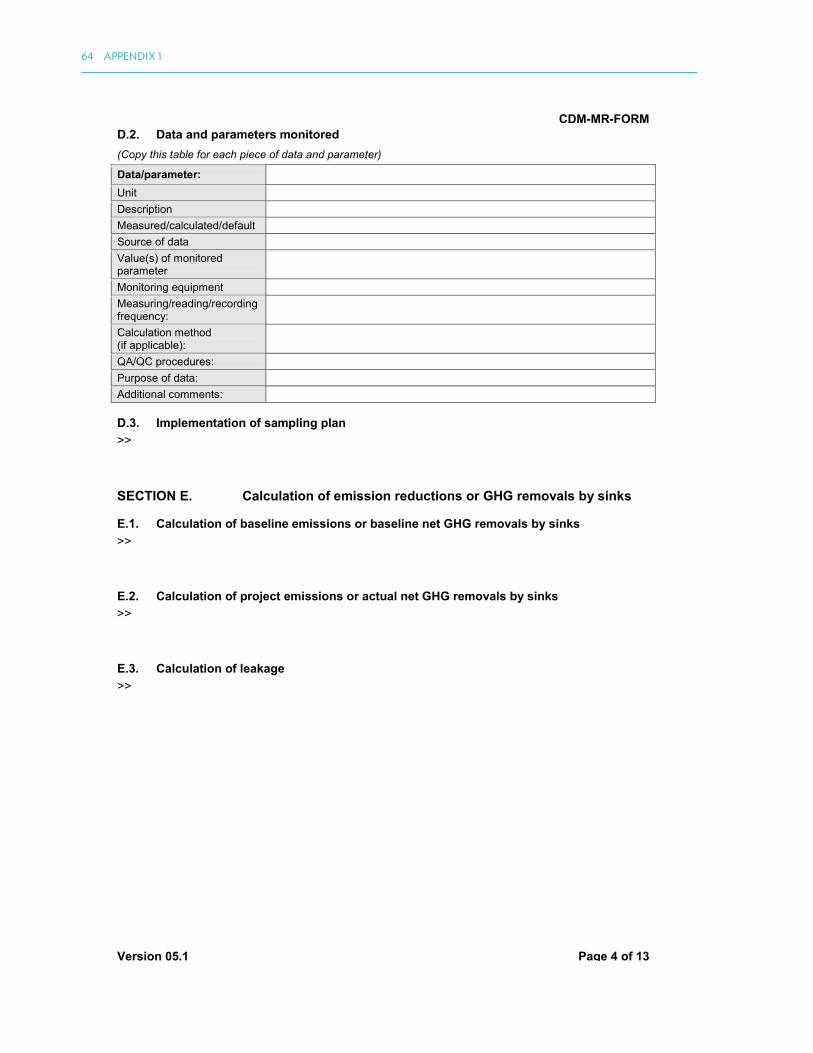
CDM-MR-FORM
Version 05.1 Page 4 of 13
D.2. Data and parameters monitored (Copy this table for each piece of data and parameter)
Data/parameter: Unit
Description
Measured/calculated/default
Source of data
Value(s) of monitored parameter
Monitoring equipment
Measuring/reading/recording frequency:
Calculation method(if applicable):
QA/QC procedures:
Purpose of data:
Additional comments:
D.3. Implementation of sampling plan >>
SECTION E. Calculation of emission reductions or GHG removals by sinks
E.1. Calculation of baseline emissions or baseline net GHG removals by sinks >>
E.2. Calculation of project emissions or actual net GHG removals by sinks >>
E.3. Calculation of leakage >>
64 APPENDIX 1

CDM-MR-FORM
Version 05.1 Page 5 of 13
E.4. Summary of calculation of emission reductions or net GHG removals by sinks
Item
Baseline emissions
or baseline net GHG removals by sinks (t CO2e)
Project emissions or actual net GHG removals by sinks (t CO2e)
Leakage (t CO2e)
GHG emission reductions or net GHG removals by sinks
(t CO2e) achieved in the monitoring period
Up to 31/12/2012
From 01/01/2013 Total amount
Total
E.5. Comparison of actual emission reductions or net GHG removals by sinks with estimates in registered PDD
Item Values estimated in ex ante calculation of registered PDD
Actual values achieved during this monitoring period
Emission reductions or GHG removals by sinks (t CO2e)
E.6. Remarks on difference from estimated value in registered PDD >>
BLANK MONITORING REPORT FORM 65

66 APPENDIX 1
CDM-MR-FORM
Version 05.1 Page 6 of 13
Appendix 1. Contact information of project participants and responsible persons/entities
Project participant and/or responsible person/ entity
Project participant Person/entity responsible for completing the CDM-MR-FORM
Organization name Street/P.O. Box Building City State/region Postcode Country Telephone Fax E-mail Website Contact person Title Salutation Last name Middle name First name Department Mobile Direct fax Direct tel. Personal e-mail

67
Appendix 2 contains a sample sustainable development report from Improving Kiln Eiciency in the Brick Making Industry in Bangladesh (Bundle-2). Information in this appendix has been drawn from publicly available information about the project, available on the CDM website.
If you would like to learn more about the Improving Kiln Eiciency in the Brick Making Industry inBangladesh (Bundle-2), please visit the project page on the CDM website: https://cdm.unfccc.int/Projects/DB/SGS-UKL1268326008.88/view
You can also download an electronic copy of the sustainable development report from Improving Kiln Eiciency in the Brick Making Industry in Bangladesh (Bundle-2) here: https://cdm.unfccc.int/ilestorage/X/I/T/XITCWOH9ZJ4BU58VDRGYMELQKNSA2P/SDC%20Description%20Report_6085.pdf?t=S2p8bzZ4dXZyfDCbmpjSiyoJs6MYfAsb9GVN
APPENDIX 2: SAMPLE SUSTAINABLE DEVELOPMENT REPORT

68 APPENDIX 2
Clean Development MechanismSustainable Development co-Beneits Descripion Report1
CDM project acivity informaion
Title Improving Kiln Eiciency in the Brick Making Industry inBangladesh (Bundle-2)
Project acivity reference no. 6085Type Project AcivitySectoral Scope Manufacturing industries (4)Host Party Bangladesh
Report informaionSubmission date 30.07.2015Publicaion no. 1Original language EnglishThird party veriier (willing) YesName of third party veriier and/or comments
Contact informaionTitle Mr.Name (irst name, surname) Jose Andreu
Organisaion Internaional Bank for Reconstrucion andDevelopment
1. This SD descripion report produced contains advice, opinions and statements of various informaion providers. TheUNFCCC and the CDM Execuive Board does not represent or endorse the accuracy or reliability of any advice,opinion, statement or other informaion provided by any informaion provider. Reliance upon any such advice, opinion,statement, or other informaion shall also be at own risk.
1

SAMPLE SUSTAINABLE DEVELOPMENT REPORT 69
Overview of sustainable development co-Beneits
A. The extent of environmental co-Beneits:
N/A Partly Slightly HighlyReducing Sox ●Reducing Nox ●Reducing Fly ash ●Reducing suspended pariculate mater (SPM) ●Reducing Non Methane Volaile OrganicCompounds (NMVOCs) ●
Reducing Noise Polluion ●Reducing Odors ●Reducing Dust ●
Air
Other air quality improvements ●Prevening end of life products/equipment(solid waste) ●
Producing/using compost ●Producing/using manure, mineral ferilizer orother soil nutrients ●
Irrigaion ●Prevening soil erosion ●Minimum illage
Land
Other means to improve land quality ●Improving management/control of wastewater ●Saving/conserving of water ●Improving reliability/accessibility of watersupply ●
Puriicaion/cleaner water supply ●Improving ecological state of water bodies ●
Wat
er
Other means to improve water ●Protecing mineral resources ●Protecing/enhancing plant life ●Protecing/enhancing species diversity ●Protecing/enhancing forests ●
Nat
ural
Reso
urce
s
Protecing/enhancing other depletable naturalresources ●
B. The extent of social co-Beneits:
N/A Partly Slightly HighlyNew long-term jobs ●New short-term jobs ●New sources of income generaion ●Jo
bs
Other employment opportuniies ●Disease prevenion ●Reducing accidents ●Reducing crime ●Preserving food ●Reducing health damaging indoor air polluion ●Enhancing health services ●Improving sanitaion and waste management ●
Heal
th &
Safe
ty
Other health and safety improvement ●
2

70 APPENDIX 2
Job-related training ●Enhanced educaional services ●Project-related knowledge disseminaion ●
Educ
aion
Other educaional beneits ●Improving working condiions ●Community or rural advancement ●Poverty alleviaion (more people above povertylevel) ●
Improving wealth distribuion/generaion ofincome and assets ●
Increased municipal revenues ●Opimized women's empowerment ●Reduced traic congesion ●
Wel
fare
Other welfare beneits ●
C. The extent of economic co-Beneits:
N/A Partly Slightly HighlyNew investments ●New industrial/commercial aciviies ●New infrastructure ●Enhancement of producivity ●Reducion of producion costs (services) ●New business opportuniies ●
Grow
th
Other economic beneits ●Improvement in supply of energy ●Access to energy ●Afordability and/or reliability of energy ●En
ergy
Other energy improvements ●Introducing/developing/difusing importedtechnology ●
Introducing/developing/difusing localtechnology ●
Adaptaion of new technologies to localcircumstances ●
Know-how aciviies for a technology ●
Tech
nolo
gy
Other technological beneits ●Reducion of foreign dependency ●
Bala
nce
ofpa
ymen
ts
Other macro-economic beneits ●
D. Further informaion:
N/A Partly Slightly Highly
●
3

SAMPLE SUSTAINABLE DEVELOPMENT REPORT 71
Detailed descripion
A. Environmental co-Beneits
No co-beneits related to land, water are described.
Indicator Speciicaion Extent
The CDM project acivity improves air quality by reducing air pollutants as follows:
SOx N/ANOx N/A
Fly ash emissions
In Bangladesh, the clay bricks are tradiionallymanufactured through Fixed Chimney Kilns (FCK). Theexhaust gas generated from the kiln is vent into theatmosphere through a chimney and the heaingeiciency of brick burning process is low. In contrast, theHybrid Hofman Kilns (HHK) present a much moreeicient kiln design in which 1) the kiln exhaust gas is re-used for drying the green bricks (instead of beingreleased into the atmosphere); 2) coal paricles aremixed with the clay for improved burning of the bricks.This results in reduced ly ash emissions in the brickmaking process in comparison to the baseline scenariowhich leads to insuicient combusion and highemissions. The main reasons for this are that the greenbrick making process traps coal pariculates inside of thebrick prevening them from becoming air borne and thusreduces the volume of ly ash.
Partly
SPM
The baseline FCKs release the kiln exhaust gas directly tothe atmosphere whereas the HHKs reuses the exhaustgas to dry the green bricks. This process prevents theunburnt coal paricles of the kiln from being releasedinto the atmosphere and thus reduces SPM emissions.
Partly
NMVOCs N/ANoise N/AOdors N/A
Dust
The baseline FCKs release the kiln exhaust gas directly tothe atmosphere whereas the HHKs reuses the exhaustgas to dry the green bricks. This process prevents theunburnt coal paricles of the kiln from being releasedinto the atmosphere and thus reduces level of dust.
Partly
Air
Other air qualityimprovements N/A
The CDM project acivity protects or enhance depletable natural resources as follows:
Nat
ural
Reso
urce
s
Mineral resources
The HHK technology uses a mix of pulverised coal andclay to ensure improved and proper burning of the brick.In addiion the waste heat from the kiln is collected andre-used to dry the green bricks in a drying chamber(before the bricks enter the kiln). The HHK brick makingprocess results in reduced use of coal by 45-50%. HHKstypically require 12-13 tons of coal for every 100,000bricks produced, whereas tradiional FCKs (the baseline)
Partly
4

72 APPENDIX 2
New long-term jobs > 1 year - 100
New short-term jobs < 1 year -
require around 24-25 tons of coal to produce 100,000bricks. HHKs consume only half of the energy that FCKsneed.
Plant life
In areas where there are clusters of tradiional FCKs,plant life and culivated crops are seriously afected bythe ly ash released into the atmosphere. This is not thecase for HHKs, that release less ly ash than tradiionalkilns.
Slightly
Species diversity N/AForests N/AOther depletable naturalresources N/A
B. Social co-Beneits
All available social co-beneits are described.
Indicator Speciicaion ExtentThe CDM project acivity creates new job opportuniies including income generaion as follows:
New long term jobs
In Bangladesh, tradiional FCKs are typically operaionalfor 5-6 months throughout the year as a result ofmonsoon season loods. As a result, the brick makingjobs in FCK are seasonal in nature. In contrast, theHybrid Hofman Kilns are designed so to be operaionalyear-round while not afected by the monsoon loods.Brick workers have full-ime job opportuniies as aresult.
Highly
New short term jobs N/A
Income generaion N/A
Jobs
Other employmentopportuniies N/A
The CDM results in health and safety improvements as follows:Reducion of diseases,disease prevenion N/A
Reducion of accidents N/AReducion of crime N/APreservaion of food N/AReducing health damagingindoor air polluion N/A
Heal
th &
safe
ty
Enhancement of healthservices
The HHK units included under this CDM project provideenhanced health services for the brick workers comparedto the industry standard. A doctor, contracted by theHHKs, conducts bi-monthly health checkups for workersonsite. Generic medicaions are also provided to theworkers at the in-house clinic built by the kilns. Brickworkers beneit from easy access and regular healthcheck-ups, which is typically not provided by tradiionalFCK kilns and which is very diicult to access otherwisegiven their social-economic and rural background inBangladesh. The enhancement of health services is partof the Community Beneit Plan (CBP) as per the EmissionReducion Purchase Agreement between Industrial andInfrastructure Development Company Ltd. (the PE) andthe Community Development Carbon Fund (CDCF),
Highly
5

SAMPLE SUSTAINABLE DEVELOPMENT REPORT 73
managed by the World Bank. The CBP implementaion isfunded through the CER revenue.
Improved sanitaion andwaste management
The HHKs constructed separate sanitaion and washingfaciliies on site for men and women workersrespecively. In addiion the HHKs have built dedicatedvenues for workers to rest during of-work period. This isa signiicant improvement relaive to tradiional FCKsites, where someimes even the basic sanitaion facilityis not constructed. In addiion, due to their operaion ona leased land, the sanitaion faciliies for FCKs are mostlyrough and not up to the standard. The improvedsanitaion is part of the Community Beneit Plan (CBP) asper the Emission Reducion Purchase Agreementbetween Industrial and Infrastructure DevelopmentCompany Ltd. (the PE) and the Community DevelopmentCarbon Fund (CDCF), managed by the World Bank. TheCBP implementaion is funded through the CER revenue.
Highly
Other health and safetyimprovements
Worker safety is signiicantly improved relaive to thebaseline, thanks to onsite training on OccupaionalHealth and Safety, the deployment of safety signs andinstrucions, the installaion of fencing arounddangerous machinery and the provision of task-speciicsafety gear for workers, including protecive footwear,gloves, goggles, masks etc. These labor pracices are notthe norm in the tradiional FCK brick making industry inBangladesh, exposing brick workers to hazardousworking environments. The occupaional safetyimprovements and training is included in the CommunityBeneit Plan (CBP) as per the Emission ReducionPurchase Agreement between Industrial andInfrastructure Development Company Ltd. (the PE) andthe Community Development Carbon Fund (CDCF),managed by the World Bank. The CBP implementaion isfunded through the CER revenue.
Highly
The CDM project acivity facilitates educaion, disseminaion of informaion, research or increasesawareness as follows:
Job related training
Onsite training of Occupaional Health and Safety isprovided for all HHK brick workers. Speciic professionalskill training such as ire masters is conducted byexternal experts.
Partly
Enhanced educaionalservices N/A
Project related knowledgedisseminaion N/A
Educ
aion
Other educaional beneits N/AThe CDM project acivity improves local living and working condiions as follows:
Improvement of workingcondiions
The working condiions and livelihoods of brick workersat HHK sites are signiicantly improved relaive totradiional FCK sites. Workers have access to year-roundemployment and a permanent source of income, accessto sanitaion and washing faciliies on site, bi-monthlydoctor check-ups and a medical faciliies as well assheltered areas to rest.
Highly
Community or ruraluplitment N/A
Poverty alleviaion N/A
Wel
fare
Changes in distribuion and/or generaion of income andassets
N/A
6
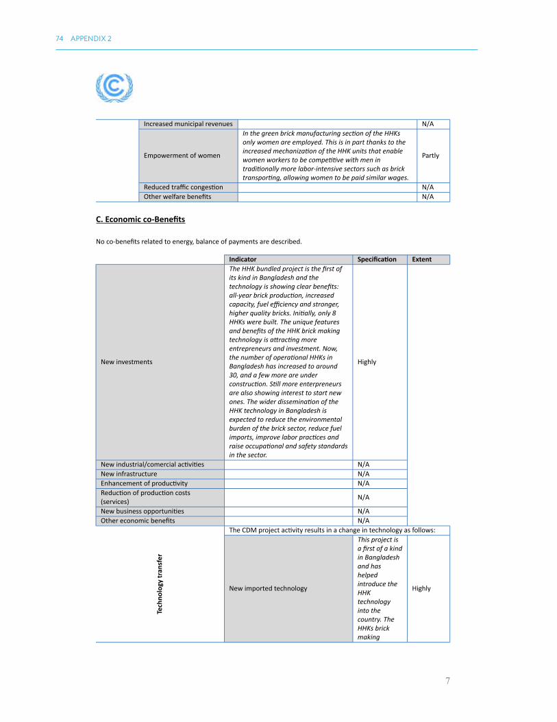
Increased municipal revenues N/A
Empowerment of women
In the green brick manufacturing secion of the HHKsonly women are employed. This is in part thanks to theincreased mechanizaion of the HHK units that enablewomen workers to be compeiive with men intradiionally more labor-intensive sectors such as bricktransporing, allowing women to be paid similar wages.
Partly
Reduced traic congesion N/AOther welfare beneits N/A
C. Economic co-Beneits
No co-beneits related to energy, balance of payments are described.
Indicator Speciicaion Extent
New investments
The HHK bundled project is the irst ofits kind in Bangladesh and thetechnology is showing clear beneits:all-year brick producion, increasedcapacity, fuel eiciency and stronger,higher quality bricks. Iniially, only 8HHKs were built. The unique featuresand beneits of the HHK brick makingtechnology is atracing moreentrepreneurs and investment. Now,the number of operaional HHKs inBangladesh has increased to around30, and a few more are underconstrucion. Sill more enterpreneursare also showing interest to start newones. The wider disseminaion of theHHK technology in Bangladesh isexpected to reduce the environmentalburden of the brick sector, reduce fuelimports, improve labor pracices andraise occupaional and safety standardsin the sector.
Highly
New industrial/comercial aciviies N/ANew infrastructure N/AEnhancement of producivity N/AReducion of producion costs(services) N/A
New business opportuniies N/AOther economic beneits N/A
The CDM project acivity results in a change in technology as follows:
Tech
nolo
gy tr
ansf
er
New imported technology
This project isa irst of a kindin Bangladeshand hashelpedintroduce theHHKtechnologyinto thecountry. TheHHKs brickmaking
Highly
7
74 APPENDIX 2

technologywas originallydesigned inGermany andadopted bymany othercountries. Thetechnologyemployed bythis CDMproject isimported fromChina.TradiionalFixed ChimneyKilns (FCK)which arewidely used inBangladeshare similar tothe Bull'sTrench Kilntechnologywhich isenergy-intensive andheavilypolluing.Unlike thebaseline, theHHKtechnology isenergyeicient(requiring only45-55% of fuelfor the sameamount ofbricksproduced byFCK). Thesekilns canoperate year-round. Theproducedbricks havebeter strengthand intensity.The mostimportantfeature of theHHKs is that itdecreases theair polluionremarkably.
New local technology N/A
Adaptaion of new viable technologiesThe HHK ismainly atechnology
Partly
8
SAMPLE SUSTAINABLE DEVELOPMENT REPORT 75

imported fromChina. In theiniial phase oftechnologyadopion, theHHKs facedseveralproblemsincluding thediference inclaycharacterisics,topography ofthe kiln plant,anddiferences inclimate, whichafected HHKplantoperaion. Thekiln ownersmade greateforts toadapt the HHKtechnology tothe localBangladeshicircumstances,namely adjustthe duraion ofthe dryingprocess tocontrol themoisture leveland, heightenthe base of theHHK plant toavoid loodingduring themonsoonseason.
Know-how aciviies for a technology
The ireman ina HHK plays avery vital rolefor itssuccessful andsmoothoperaion. Inthe earlystage, most ofthe HHKsdepended onire mastersfrom China.Later on, localire mastersreceivedtraining fromthe Chinese
Highly
9
76 APPENDIX 2

ire mastersand built up itsown capacity.Now most ofthe kilns arerunningindependentlyby local iremasters.
Other technological beneits N/A
Bala
nce
of p
aym
ents
The CDM project acivity results in improving the country's balance ofpayments as follows:
10
SAMPLE SUSTAINABLE DEVELOPMENT REPORT 77

78
Table A3.1 below shows a comprehensive list of tasks and deliverables relevant to a PoA or CPA. CMEs can use this list as a starting point to develop their own list of tasks and deliverables for their own PoA or CPA.
Once a CME has developed their own list, then responsibilities may be assigned to the diferent parties and personnel involved in the project. This division of responsibilities can be shown using a Responsibility Assignment Matrix (or RACI). An example of a RACI is shown in Table A3.2. A RACI table uses the following terminology:
• Responsible (R): personnel or parties who are working on the task
• Accountable (A): those who have inal responsibility for the outcome of the task
• Consulted (C): personnel or parties who are contacted as part of the process to provide their opinions or input their expertise on a particular task or activity
• Informed (I): personnel or parties who are kept up to date with progress, often only at the completion of a task or activity.
APPENDIX 3: LIST OF TASKS AND DELIVERABLES RELEVANT TO A PoA OR CPA
Table A3.1: Comprehensive List of Tasks and Deliverables
Monitoring of
implementation of
CPA
Distribution and installation
of PoA technologies
Installation records
Training of entities
distributing and installing
PoA technology
Training plan and records
Installation manuals
Training of users of
technology
Training plan and records
Operating manuals
Survey to confirm correction
installation of PoA
technology
Survey plan, survey checklist
and survey report
Testing of performance of
equipment (in case PoA
requires compliance with a
performance specification)
Test report
Monitoring
and reporting
process Activity / tasks Deliverables

LIST OF TASKS AND DELIVERABLES RELEVANT TO A POA OR CPA 79
Table A3.1 continued
Source: KFW Bankengruppe. 2013. MRV Manual for CDM Programme of Activities. https://www.kfw-entwicklungsbank.de/PDF/Entwicklungsinanzierung/Umwelt-und-Klima/Klimaschutzfonds/PDF-Dokumente-Klimaschutzfonds/MRV-Manual-for-CDM-PoA.pdf
Monitoring
equipment
Purchase and installation of
suitable monitoring
equipment which comply
with the requirements
stipulated by the monitoring
plan
Equipment manual and
technical specifications
Installation records and testing
Factory calibration records
Training of personnel in
operating and maintenance of
monitoring equipment
Training plan and training
records
Operating and maintenance
manual
Calibration of monitoring
equipment
Calibration records
Repairing / replacing defect
monitoring equipment
Repair record / record of
replacement
Monitoring of
parameters
Perform measurements and
record measurement results
Measurement records
Read meters and record
meter readings
Logbooks
Daily records
Monitoring surveys Development of plan for
survey / sampling plan,
including determination of
sample size
Survey / sampling plan
Execution of survey Questionnaire
Reporting form
Survey records
Statistical analysis of survey
results
Survey report
Monitoring
and reporting
process Activity / tasks Deliverables
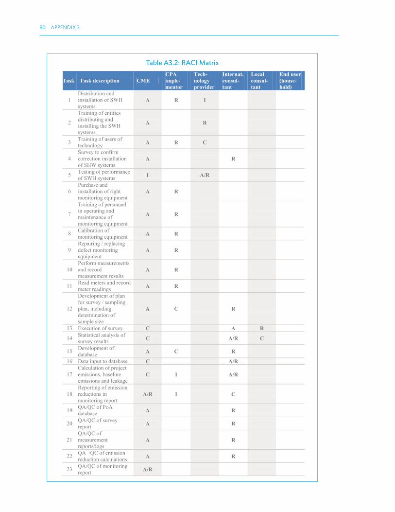
80 APPENDIX 3
Table A3.2: RACI Matrix
Task Task description CME
CPA
imple-
mentor
Tech-
nology
provider
Internat.
consul-
tant
Local
consul-
tant
End user
(house-
hold)
1
Distribution and
installation of SWH
systems A R I
2
Training of entities
distributing and
installing the SWH
systems
A R
3 Training of users of
technology A R C
4
Survey to confirm
correction installation
of SHW systems A R
5 Testing of performance
of SWH systems I A/R
6
Purchase and
installation of right
monitoring equipment A R
7
Training of personnel
in operating and
maintenance of
monitoring equipment
A R
8 Calibration of
monitoring equipment A R
9
Repairing / replacing
defect monitoring
equipment A R
10
Perform measurements
and record
measurement results A R
11 Read meters and record
meter readings A R
12
Development of plan
for survey / sampling
plan, including
determination of
sample size
A C R
13 Execution of survey C A R
14 Statistical analysis of
survey results C A/R C
15 Development of
database A C R
16 Data input to database C A/R
17
Calculation of project
emissions, baseline
emissions and leakage C I A/R
18
Reporting of emission
reductions in
monitoring report A/R I C
19 QA/QC of PoA
database A R
20 QA/QC of survey
report A R
21
QA/QC of
measurement
reports/logs A R
22 QA /QC of emission
reduction calculations A R
23 QA/QC of monitoring
report A/R

81
Appendix 4 provides additional information on PoA monitoring. The monitoring framework for a PoA will have been established during the CDM-POA-DD stage. The purpose of this appendix is to explain the steps needed to select a particular methodology. While the selection of monitoring methodologies does not directly impact upon monitoring and veriication, the information will be useful background for CMEs involved in monitoring and veriication.1
CDM methodologies should be applied in the same way to both PoAs and stand-alone CDM projects. In practice, CDM methodologies are usually applied equally in stand-alone and large-scale CDM activities. However, for small-scale CDM activities, there can be diferences in the application of monitoring methodologies in PoAs and stand-alone CDM projects. This is because of the diference in scale between a stand-alone project and a PoA activity. Small-scale methodologies often involve simpliications that are not signiicant when applied to a single project. However, when they are applied at scale across a PoA, then a simpliication can have a signiicant efect on monitoring outcomes.
Additional requirements for monitoring methodologies within a PoA focus on negating possible errors that would apply in these situations. The practical efect of these additional requirements is to increase the quantity of data necessary to be collected.
Table A4.1 below shows methodologies with speciic PoA requirements. CMEs should note that although the majority of methodologies apply to small-scale activities, there are large-scale activities that also have diferent PoA requirements.
Table A4.1: Methodologies with Speciic PoA Requirements
1 KFW Bankengruppe. 2013. MRV Manual for CDM Programme of Activities. https://www.kfw-entwicklungsbank.de/PDF/Entwicklungsinanzierung/Umwelt-und-Klima/Klimaschutzfonds/PDF-Dokumente-Klimaschutzfonds/MRV-Manual-for-CDM-PoA.pdf
APPENDIX 4: MONITORING METHODOLOGIES WITH SPECIFIC PoA REQUIREMENTS
Small scale methodology Large scale methodology
Renewable energy
AMS-I.A, AMS-I.B, AMS-I.C, AMS-I.D, AMS-
I.E, AMS-I.F, AMS-I.J, AMS-I.KACM0002
Energy distribution / Energy demand
AMS-II.A, AMS-II.B, AMS-II.C, AMS-II.D,
AMS-II.E, AMS-II.F, AMS-II.G, AMS-II.H, AMS-
II.I, AMS-II.K, AMS-III.AG, AMS-III.AH, AMS-
III.AM, AMS-III.AN, AMS-III.AR, AMS-III.AV
-
Fugitive emissions from fuel
AM0009
Waste handling and disposal
AMS-III.B, AMS-III.D, AMS-III.E, AMS-III.F,
AMS-III.I, AMS-III.J, AMS-III.AF, AMS-III.AO
ACM0001, ACM0010,
ACM0014, ACM0022
Chemical/manufacturing industries
AMS-III.K, AMS-III.L, AMS-III.M, AMS-III.N,
AMS-III.P, AMS-III.Q, AMS-III.Z, AMS-III.AC,
AMS-III.AS, AMS-III.BG
-
Transport
AMS-III.S, AMS-III.AA, AMS-III.AY, AMS-
III.BC
-

82
Although CDM methodologies should be applied in the same way to both PoAs and stand-alone CDM projects, in certain cases, speciic monitoring methodologies might have speciic PoA requirements.
Appendix 5 provides further explanation of CDM methodologies and tools within a PoA. Appendix 5 speciically discusses the combination of CDM methodologies and tools within a PoA.1
A PoA can use a combination of methodologies and tools; however, the combination must be approved by the Executive Board.2 In addition, if a combination of methodologies is chosen, then this combination must be applied to all CPAs within the PoA.3
CMEs should be aware of the following limitations to PoAs using a combination of methodologies:
(i) The approval process for a combination methodology is lengthy and contains many risks.
(ii) To request a combination methodology, CMEs must submit the CDM-POA-DD and CDM-CPA-DD along with the request. The PoA documentation is then examined by the relevant working group. After the working group has examined the request it is then submitted to the Executive Board, which will make the inal decision.
(iii) The result of this is that the CME must expend signiicant time and efort without being certain that the combination methodology will be approved. This presents a signiicant risk for the PoA and must be carefully considered by the CME.
(iv) The combination of methodologies must be applied across all CPAs within a PoA.
This limits the options available to CMEs, as methodologies do not always match what can be practically implemented by the CME. The two examples on the following page from the World Bank PoA guide serve to illustrate these limitations.
Example A1
A CME supporting the development of hydropower activities cannot include both of-grid and grid-connected CPAs within the same PoA, because they require two diferent small-scale methodologies (AMS.I.A for of-grid renewable electricity generation projects and AMS.I.D for grid-connected ones). Despite the similarity of the two methodologies and the use of the same technology, such a programme will require two distinct PoAs, efectively doubling the CDM transaction costs of setting up the programme.
1 World Bank. 2012. PoA Developing CDM Programme of Activities: A Guidebook. http://cpf.wbcarboninance.org/system/iles/ PoA_Guidebook_SouthPole.pdf
2 UNFCCC. 2009. Annex 31: Procedures for Approval of the Application of Multiple Methodologies to a Programme of Activities. https://cdm.unfccc.int/EB/047/eb47_repan31.pdf
3 Footnote 1.
APPENDIX 5: COMBINATION OF CDM METHODOLOGIES AND TOOLS WITHIN A PoA

COMBINATION OF CDM METHODOLOGIES AND TOOLS WITHIN A POA 83
Example A2
Methane avoidance activities (landill, wastewater treatment) are typically projects that require a combination of methodologies. For instance, a CME supporting the development of biogas plants with heat and/or electricity generation will need diferent methodologies—AMS.III.H for the digester; AMS.I.C for heat (or heat and electricity); AMS.I.D for electricity. Despite the fact that the generation of heat and/or electricity is a secondary measure (the main measure is the implementation of the digester), such a programme cannot be implemented as one PoA.
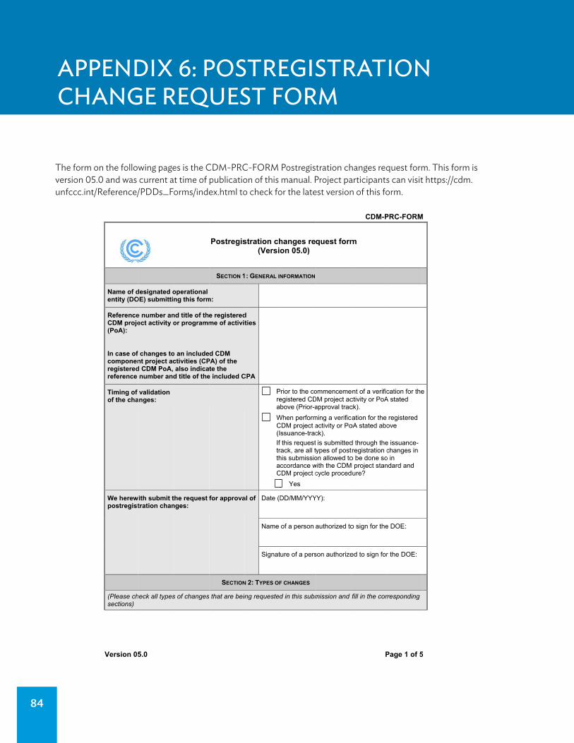
84
APPENDIX 6: POSTREGISTRATION CHANGE REQUEST FORM
5
Name of dentity (DO
ReferenceCDM proje(PoA):
In case of componenregisteredreference
Timing of of the cha
We herewpostregist
(Please chsections)
5
designated oOE) submittin
e number anect activity o
f changes tont project acd CDM PoA, number and
validation anges:
with submit ttration chan
heck all types
operational ng this form
nd title of theor programm
o an includectivities (CPalso indica
d title of the
the request nges:
s of changes
Postregis
SECTION 1
m:
e registeredme of activit
d CDM PA) of the te the
e included C
for approva
SECTION
that are bein
stration ch(Versio
1: GENERAL IN
dties
CPA
P
rea
W
C(I
If trthacC
al of Date (D
Name
Signat
N 2: TYPES OF
ng requested
hanges reon 05.0)
NFORMATION
Prior to the co
egistered CDbove (Prior-a
When perform
CDM project assuance-trac
this requestrack, are all this submissioccordance w
CDM project c
Yes
DD/MM/YYY
of a person
ure of a pers
F CHANGES
d in this subm
quest form
ommenceme
DM project acapproval trac
ming a verific
activity or Pock).
is submittedypes of poston allowed towith the CDMcycle proced
YY):
authorized to
son authorize
mission and
CDM-P
P
m
ent of a verific
ctivity or PoAck).
cation for the
oA stated abo
d through thetregistration co be done so
M project standure?
o sign for the
ed to sign for
fill in the cor
PRC-FORM
5
cation for the
A stated
registered
ove
e issuance-changes in
o in ndard and
e DOE:
r the DOE:
rresponding
M
5
e
The form on the following pages is the CDM-PRC-FORM Postregistration changes request form. This form is version 05.0 and was current at time of publication of this manual. Project participants can visit https://cdm.unfccc.int/Reference/PDDs_Forms/index.html to check for the latest version of this form.
Version 055.0 PPage 1 of 55

POSTREGISTRATION CHANGE REQUEST FORM 85
CDM-PRC-FORM
Version 05.0 Page 2 of 5
A. Temporary deviations from the monitoring plan as described in the registered PDD, PoA-DD or CPA-DD, the applied baseline and monitoring methodology or standardized baseline
Applicable period for proposed deviations (inclusive): ______________
DD / MM / YYYY
(start date of the earliest included deviation)
to
_____________
DD / MM / YYYY
(end date of the latest included deviation)
B. Corrections that do not affect project/ programme design
C. Change to the start date of the crediting period of the project activity or component project activity (CPA) of a PoA
Is the original start date prior to the date of registration of the project activity or PoA?
No
(If yes, it is not allowed to change the start date in accordance with the CDM project cycle procedure.)
Is the change more than two years (four years for a least developed country) from the original start date?
No
(If yes, it is not allowed to change the start date in accordance with the CDM project cycle procedure.)
Does the change to the start date of the crediting period in this request require prior approval as specified in the CDM project standard?
Yes
(If no, do not use this form and notify the secretariat in accordance with the CDM project cycle procedure.)
Proposed new start date of the crediting period: ______________
DD / MM / YYYY
D. Inclusion of a monitoring plan in the registered PDD, PoA-DD or CPA-DD, if a monitoring plan was not included at the time of their registration
Timing of the request for approval of changes:
Prior to the submission of request for issuance for
the first monitoring period
Together with the submission of request for
issuance for the first monitoring period
E. Permanent changes to the monitoring plan as described in the registered PDD, PoA-DD, CPA-DD, or the applied baseline and monitoring methodology or standardized baseline (including changes to apply the provisions of the most recent version of the “Standard for sampling and surveys for CDM project activities and programme of activities)
Do the proposed changes refer to a later version of the applied methodology? Yes
No

86 APPENDIX 6
CDM-PRC-FORM
Version 05.0 Page 3 of 5
F. Changes to the project or programme design as described in the registered PDD or PoA-DD
(a) In the case of a registered CDM project activity, do the changes relate to:
Check all that apply:
Changes to effective output capacity
Addition of component or extension of technology
Removal or addition of sites
Actual operational parameters differ from the
expected parameters
Any consequential changes to baseline and
monitoring methodology and/or standardized baseline
None of the above (please describe the type of
changes)
(b) In the case of a registered CDM PoA, do the changes relate to:
Check all that apply:
Changes to programme boundary to:
Expand geographical coverage;
Include additional host Parties
Revisions to the eligibility criteria due to:
Version of baseline and monitoring
methodologies applied by the PoA is revised or replaced subsequent to being placed on hold;
Revision of the eligibility criteria of a registered
PoA is initiated by the Board at any time during the lifetime of the PoA if an issue related to environmental integrity is identified;
Use of positive lists is introduced based on the
guidelines from the Board pertaining to demonstration of additionality of small-scale/ microscale project activities.
Removal of methodologies and/or standardized
baselines from the registered PoA;
Addition or change of technologies/ measures with
or without addition or change of applied methodologies in the registered PoA-DD as follows:
Changes that allow a shift to more efficient,
less GHG-intensive or at least equivalent technologies/ measures;
Changes that introduce complementary
measures/ technologies involving mass and/or energy transfer to/from the originally registered technology/measure.
(c) For both a registered CDM project activity and PoA, do the changes necessitate to change the applied methodology or standardized baseline?
Yes
To the latest version of the methodology or
standardized baseline
To another methodology or standardized
baseline
No

CDM-PRC-FORM
Version 05.0 Page 4 of 5
G. Changes to the project design as described in the registered generic CPA-DD or specific-case CPA-DD
H. Changes specific to afforestation or reforestation project activities
I. Addition of specific case CPA-DDs corresponding to generic CPA-DDs for which a specific case CPA-DD has not been submitted at the time of request for registration of the PoA (for PoAs with more than one generic CPA-DD)
SECTION 3: DOCUMENTS SUBMITTED
For subsections A.-H. in section 2 above, confirm the following documents are attached:
(a) A completed validation report form for postregistration changes covering all changes;
(b) Clean version of one revised PDD, PoA-DD including its generic CPA-DD, or specific-case CPA-DD(s), as appropriate;
(c) Track-change version of that PDD, PoA-DD including its generic CPA-DD, or specific-case CPA-DD(s), as appropriate.
Yes
For subsection I. in section 2 above, confirm the following documents are attached:
(a) A completed specific-case CPA-DD;
(b) A validation report form for inclusion of the specific-case CPA.
Yes
Are supplemental documents attached? Yes
No
If yes, please provide titles of all documents for each type of changes that is being requested and ensure that all documents listed are submitted or links are provided:
- - - - -
POSTREGISTRATION CHANGE REQUEST FORM 87

CDM-PRC-FORM
Version 05.0 Page 5 of 5
Document information
Version Date Description
05.0 17 March 2015 Revision to:
Align provisions related to types of changes and documents submitted with the relevant requirements in the “CDM project cycle procedure” (Version 09.0) (CDM-EB65-A32-PROC);
Delete provisions related to the assessment opinion confirmation;
Change the symbol from F-CDM-PRC to CDM-PRC-FORM and minor editorial improvements;
Editorial improvement.
04.0 25 June 2014 Changes to adapt to the new provision related to standardized baselines adopted at EB 79.
03.0 29 July 2013 Changes to adapt to the new provisions on registered CPAs of a PoA adopted at EB 74.
02.0 19 December 2012 Changes to adapt to the new provision on PoAs adopted at EB 70 and editorial changes.
01.0 13 March 2012 EB 66
Initial publication.
Decision Class: Regulatory Document Type: Form Business Function: Registration Keywords: postregistration change
88 APPENDIX 6

89
APPENDIX 7: EXAMPLE MONITORING REPORT
CDM-MR-FORM
Version 04.0 Page 1 of 16
Monitoring report form
(Version 04.0)
MONITORING REPORT
Title of the project activityTata Power - Wind power project at Samana in Jamnagar district, Gujarat
Reference number of the project activity 8442
Version number of the monitoring report
1.0
Completion date of the monitoring report
27/01/2015
Registration date of the project activity 06/12/2012
Monitoring period number and duration of this monitoring period
Monitoring Period – 02 Duration – 01/01/2014 to 31/12/2014
Project participant(s)M/s. The Tata Power Company Limited, India Swedish Energy Agency, Sweden Asian Development Bank as Trustee of the Future Carbon Fund, Sweden
Host Party(ies) India
Sectoral scope and selectedmethodology(ies), and where applicable, applied standardized baseline(s)
Sectoral Scope: 1 - Energy industries (renewable - / non-renewable sources) Methodology: ACM0002 ver. 13 - Consolidated baseline methodology for grid connected electricity generation from renewable sources
Estimated amount of GHG emission reductions or net anthropogenic GHG removals by sinks for this monitoring period in the registered PDD
96,821 tCO2e
Actual GHG emission reductions or net anthropogenic GHG removals by sinks achieved in this monitoring period
68,503 tCO2e
Actual GHG emission reductions or net anthropogenic GHG removals by sinks achieved during the period up to 31 December 2012(if applicable)
0 tCO2e
Actual GHG emission reductions or net anthropogenic GHG removals by sinks achieved during the period from 1 January 2013 onwards (if applicable).
68,503 tCO2e

90 APPENDIX 7
CDM-MR-FORM
Version 04.0 Page 2 of 16
SECTION A. Description of project activity
A.1. Purpose and general description of project activity
Purpose:The proposed project activity is an initiative by The Tata Power Company Limited (TPCL) to export renewable electricity produced by Wind Electric Generators to the power deficit grid in order to decrease power shortage, diversify the grid and reduce greenhouse gas emissions.
Project Description: TPCL is the project proponent/sponsor of this wind power project with a total capacity of 50.4MW consisting of 63 Wind Energy Converter (WEC) machines of individual capacity 800 kW each. Project is getting implemented at Samana planes in Gujarat state of India which will provide reliable renewable power to the Gujarat state electricity grid which is now a part of NEWNE (Northern, Eastern, Western and North-Eastern) grid of India.
TPCL has developed this project under Clean Development Mechanism (CDM) of the United Nations Framework Convention on Climate Change (UNFCCC), as the project helps in significant reduction of GHG emissions and contributes to sustainable development of Gujarat and India. The first and last WTG under the project activity was commissioned on 29/09/2008 and 07/05/2009 respectively, and are in operation since then. The project activity was registered in UNFCCC on 06th December 2012. The total CER generation in this monitoring period is 68,503 tCO2e.
A.2. Location of project activity
The project activity is located in the Samana planes (Kalavad and Jamjodhpur taluk) of Jamnagar district in Gujarat. The nearest airport and railway station is at Jamnagar city and distance of approximately 60 kms from the project activity site.
The proposed project activity is a grid connected renewable energy project that intends to generate
electricity through utilization of wind energy. Since WECs converts kinetic energy from the “air in
motion” directly into electricity without using conventional sources like coal, oil or natural gas for
power generation, contributes to electricity generation without GHG emissions. The Project
harnesses renewable resources in the region, and thereby displacing nonrenewable natural
resources thereby ultimately leading to sustainable economic and environmental development. M/s
Enercon (India) (now known as Wind World India) is wind energy technology and equipment supplier
of TPCL and is also the operations and maintenance contractor for the Project.

EXAMPLE MONITORING REPORT 91
CDM-MR-FORM
Version 04.0 Page 3 of 16
The Project consists of 63 numbers of E-53 WECs of 800 kW each. The WEC (wind energy conversion) unit wise details of location are provided below.
Table 1: Project WEC locations
Project Name: Tata Power - Wind power project at Samana in Jamnagar district, Gujarat
Total Project Capacity - 50.4 MW Total Number of WEC’s in the Project – 63
Name of Taluka Name of Village No. of WEC
Kalavad Dhun Dhoraji 09
Mota Paanchdevada 25 Nana Paanchdevada 01
Jamjodhpur Sadodar 15 Narmana 01
Dal Devaliya 12
Table 2: Geographical Co-ordinates of the WEC’s
Sr. No WEC Name Latitude Longitude 1 TATASP-01 (2100) 22° 4' 39.900" N 70° 13' 56.940" E 2 TATASP-02 (2101) 22° 4' 47.520" N 70° 13' 53.340" E 3 TATASP-03 (2105) 22° 5' 20.520" N 70° 13' 33.300" E 4 TATASP-04 (2106) 22° 5' 30.000" N 70° 13' 29.340" E 5 TATASP-05 (2107) 22° 5' 38.160" N 70° 13' 25.380" E 6 TATASP-06 (2109) 22° 5' 57.240" N 70° 13' 17.160" E 7 TATASP-07 (2110) 22° 6' 3.600" N 70° 13' 16.200" E 8 TATASP-08 (2111) 22° 6' 11.200" N 70° 13' 14.000" E 9 TATASP-09 (2112) 22° 6' 20.940" N 70° 13' 11.340" E 10 TATASP-10 (2113) 22° 6' 30.600" N 70° 13' 8.400" E 11 TATASP-11 (2121) 22° 4' 53.700" N 70° 14' 29.700" E 12 TATASP-12 (2022) 22° 4' 52.380" N 70° 11' 32.880" E 13 TATASP-13 (2023) 22° 4' 46.320" N 70° 11' 36.900" E 14 TATASP-14 (2024) 22° 4' 48.600" N 70° 11' 52.980" E 15 TATASP-15 (2025) 22° 4' 42.660" N 70° 12' 4.140" E 16 TATASP-16 (2102) 22° 4' 57.000" N 70° 13' 50.580" E 17 TATASP-17 (2103) 22° 5' 2.820" N 70° 13' 43.020" E 18 TATASP-18 (2104) 22° 5' 11.040" N 70° 13' 35.700" E 19 TATASP-19 (2108) 22° 5' 45.300" N 70° 13' 18.900" E 20 TATASP-20 (2075) 22° 6' 41.460" N 70° 12' 31.200" E 21 TATASP-21 (2026) 22° 4' 36.900" N 70° 12' 5.760" E 22 TATASP-22 (2029) 22° 4' 12.300" N 70° 11' 59.100" E 23 TATASP-23 (2001) 22° 5' 14.760" N 70° 11' 10.500" E 24 TATASP-24 (2115) 22° 6' 45.660" N 70° 13' 6.060" E 25 TATASP-25 (2117) 22° 7' 6.120" N 70° 13' 9.540" E 26 TATASP-26 (2073) 22° 6' 22.020" N 70° 12' 28.560" E 27 TATASP-27 (2074) 22° 6' 32.700" N 70° 12' 27.540" E 28 TATASP-28 (2085) 22° 5' 38.940" N 70° 13' 2.460" E 29 TATASP-29 (2086) 22° 5' 30.900" N 70° 13' 4.620" E 30 TATASP-30 (2098) 22° 4' 21.900" N 70° 14' 13.500" E 31 TATASP-31 (2070) 22° 5' 56.820" N 70° 12' 31.380" E 32 TATASP-32 (2002) 22° 5' 25.260" N 70° 11' 7.920" E 33 TATASP-33 (2004) 22° 5' 35.940" N 70° 10' 46.740" E 34 TATASP-34 (2005) 22° 5' 42.420" N 70° 10' 49.800" E 35 TATASP-35 (2027) 22° 4' 29.160" N 70° 12' 8.760" E 36 TATASP-36 (2028) 22° 4' 21.000" N 70° 12' 7.680" E

CDM-MR-FORM
Version 04.0 Page 4 of 16
37 TATASP-37 (2068) 22° 5' 40.200" N 70° 12' 39.780" E 38 TATASP-38 (2097) 22° 3' 58.740" N 70° 14' 5.460" E 39 TATASP-39 (2077) 22° 6' 58.500" N 70° 12' 25.080" E 40 TATASP-40 (2078) 22° 7' 10.260" N 70° 12' 49.800" E 41 TATASP-41 (2116) 22° 6' 56.160" N 70° 13' 6.360" E 42 TATASP-42 (2114) 22° 6' 39.000" N 70° 13' 7.080" E 43 TATASP-43 (2048) 22° 5' 48.240" N 70° 12' 19.320" E 44 TATASP-44 (2019) 22° 5' 6.480" N 70° 11' 44.400" E 45 TATASP-45 (2123) 22° 3' 54.660" N 70° 11' 45.840" E 46 TATASP-46 (2003) 22° 5' 26.640" N 70° 10' 47.580" E 47 TATASP-47 (2008) 22° 6' 23.280" N 70° 11' 15.420" E 48 TATASP-48 (2009) 22° 6' 15.060" N 70° 11' 15.300" E 49 TATASP-49 (2010) 22° 6' 6.600" N 70° 11' 16.260" E 50 TATASP-50 (2012) 22° 5' 49.980" N 70° 11' 21.240" E 51 TATASP-51 (2013) 22° 5' 42.060" N 70° 11' 24.060" E 52 TATASP-52 (2015) 22° 5' 29.520" N 70° 11' 30.480" E 53 TATASP-53 (2016) 22° 5' 22.800" N 70° 11' 28.980" E 54 TATASP-54 (2017) 22° 5' 21.240" N 70° 11' 44.700" E 55 TATASP-55 (2038) 22° 6' 51.360" N 70° 11' 32.340" E 56 TATASP-56 (2039) 22° 6' 58.560" N 70° 11' 53.580" E 57 TATASP-57 (2040) 22° 6' 49.320" N 70° 11' 54.960" E 58 TATASP-58 (2051) 22° 5' 22.800" N 70° 12' 28.140" E 59 TATASP-59 (2052) 22° 5' 14.580" N 70° 12' 11.940" E 60 TATASP-60 (2062) 22° 4' 49.380" N 70° 12' 48.780" E 61 TATASP-61 (2063) 22° 4' 58.020" N 70° 12' 46.860" E 62 TATASP-62 (2064) 22° 5' 6.000" N 70° 12' 46.620" E 63 TATASP-63 (2066) 22° 5' 19.860" N 70° 12' 43.800" E
A.3. Parties and project participant(s)
Party involved ((host) indicates a host Party)
Private and/or public entity(ies) project participants (as applicable)
Indicate if the Party involved wishes to be considered as project participant (Yes/No)
India (Host)
M/s. The Tata Power Company Limited
No
Sweden Swedish Energy Agency Yes
Sweden Asian Development Bank as Trustee of the Future Carbon Fund
Yes
A.4. Reference of applied methodology and standardized baseline
Methodology: ACM0002 ver. 13 - Consolidated baseline methodology for grid-connected electricity generation from renewable sources1 Tools:
Tool for the demonstration and assessment of additionality2, (Version 6.1.0, EB 69, Annex 20)
1 http://cdm.unfccc.int/methodologies/DB/UB3431UT9I5KN2MUL2FGZXZ6CV71LT 2 http://cdm.unfccc.int/methodologies/PAmethodologies/tools/am-tool-01-v6.1.0.pdf
92 APPENDIX 7

CDM-MR-FORM
Version 04.0 Page 5 of 16
Tool to calculate the emission factor for an electricity system3, (Version 2.2.1, EB 63, Annex 19)
A.5. Crediting period of project activity
Choice of crediting period : Fixed crediting period
Length of the crediting period : 10 years
Crediting period duration : 06/12/2012 – 05/12/2022
Current Monitoring period : 01/01/2014 – 31/12/2014
A.6. Contact information of responsible persons/ entities
M/s. The Tata Power Company Limited is the entity responsible for completing the CDM-MR-FORM and is also the project participant as indicated in Appendix 1.
SECTION B. Implementation of project activity
B.1. Description of implemented registered project activity
The first WEG under the project activity was commissioned on 29/09/2008 and last WEG under the project activity was commissioned on 07/05/2009. The project activity consists of total 63 WEGs (800 kW) of Enercon make E – 53. The commissioning date for all the WEGs include in the project activity is given in the table below: Table 3: WEC commissioning details:
Commissioning dates
No of WEC’s commissioned Capacity (MW)
29/09/2008 11 8.8 30/09/2008 04 3.2 14/11/2008 08 6.4 29/11/2008 03 2.4 08/12/2008 04 3.2 11/12/2008 01 0.8 05/01/2009 05 4.0 16/01/2009 01 0.8 06/05/2009 15 12.0 07/05/2009 11 8.8
Total 63 50.4
The Project involves 63-wind energy converters (WECs) of Enercon make (800 kW E-53) with internal electrical lines connecting the Project with evacuation facility. The WECs generates 3-phase power at 400V, which is stepped up to 33 kV. The Project can operate in the frequency range of 47.5–51.5 Hz and in the voltage range of 400 V ± 10%.
3 https://cdm.unfccc.int/methodologies/PAmethodologies/tools/am-tool-07-v2.2.1.pdf
EXAMPLE MONITORING REPORT 93

CDM-MR-FORM
Version 04.0 Page 6 of 16
The other salient features of the state-of-art-technology are:
Gearless Construction - Rotor & Generator Mounted on same shaft eliminating the Gearbox.
Variable speed function – has the speed range of 12 to 29 RPM thereby ensuring optimum efficiency at all times.
Variable Pitch functions ensuring maximum energy capture. Near Unity Power Factor at all times. Minimum drawl (less than 1% of kWh generated) of Reactive Power from the grid. No voltage peaks at any time. Operating range of the WEC with voltage fluctuation of -20 to +20%. Rotor diameter is 53m & having Swept area of 2205 m², Blade material used is Fibreglass
(reinforced epoxy) with integral lightning protection Three Independent Braking Systems with power back up supply. Generator achieving rated output at only 29 rpm. Starts Generation of power at wind speed of 3 m/s.
E-53 / 800 kW TECHNICAL DATA:
0.8 MW (E-53, Enercon Make)
Sr. No. Particulars Specifications
1 Turbine Model Enercon E-53 2 Rated Power 800 kW 3 Rotor Diameter 53 meters 4 Hub height 75 meters
5 Turbine Type Direct driven, upwind, horizontal axis WEC with variable rotor speed
6 Power Regulation Independent pitch system for each blade 7 Design life time 20 years 8 Cut-in wind speed 2.5 m/s 9 Rated wind speed 12 m/s 10 Cut-out wind sped 28-34 m/s 11 Extreme Wind Speed 59.5 m/s 12 Rated rotational speed 32 rpm
13 Operating range rot. speed 12-29 rpm
14 Orientation Upwind 15 No. of blades 3 16 Blade material Glass Fibre Epoxy Reinforced
94 APPENDIX 7
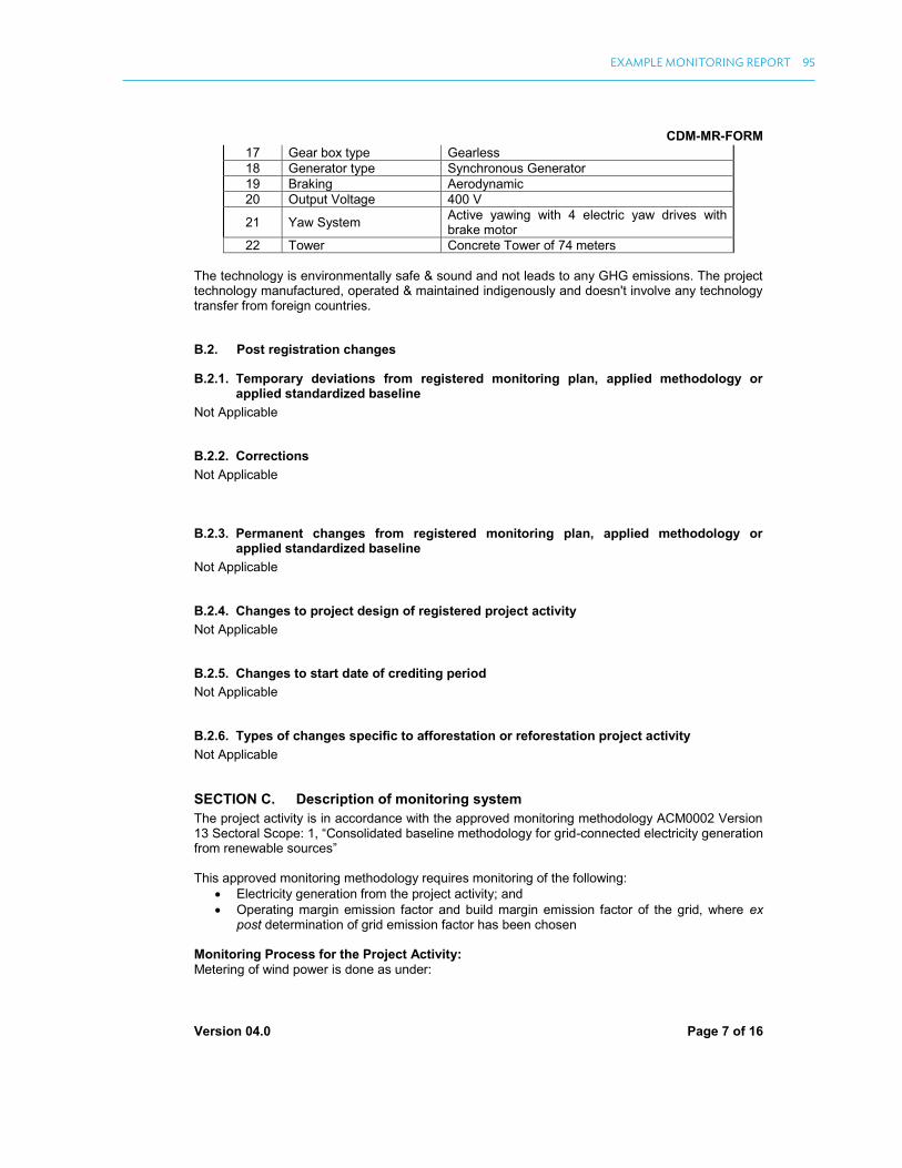
CDM-MR-FORM
Version 04.0 Page 7 of 16
17 Gear box type Gearless 18 Generator type Synchronous Generator 19 Braking Aerodynamic 20 Output Voltage 400 V
21 Yaw System Active yawing with 4 electric yaw drives with brake motor
22 Tower Concrete Tower of 74 meters The technology is environmentally safe & sound and not leads to any GHG emissions. The project technology manufactured, operated & maintained indigenously and doesn't involve any technology transfer from foreign countries.
B.2. Post registration changes
B.2.1. Temporary deviations from registered monitoring plan, applied methodology or applied standardized baseline
Not Applicable
B.2.2. Corrections
Not Applicable
B.2.3. Permanent changes from registered monitoring plan, applied methodology or applied standardized baseline
Not Applicable
B.2.4. Changes to project design of registered project activity
Not Applicable
B.2.5. Changes to start date of crediting period
Not Applicable
B.2.6. Types of changes specific to afforestation or reforestation project activity
Not Applicable
SECTION C. Description of monitoring system
The project activity is in accordance with the approved monitoring methodology ACM0002 Version 13 Sectoral Scope: 1, “Consolidated baseline methodology for grid-connected electricity generation from renewable sources” This approved monitoring methodology requires monitoring of the following:
Electricity generation from the project activity; and Operating margin emission factor and build margin emission factor of the grid, where ex
post determination of grid emission factor has been chosen Monitoring Process for the Project Activity:Metering of wind power is done as under:
EXAMPLE MONITORING REPORT 95

CDM-MR-FORM
Version 04.0 Page 8 of 16
Monthly joint meter reading is taken at Sadodar (33/220kV) substation meters, where all WECs which are part and not part of the project, are connected, by the representative of GETCO (Gujarat Electricity Transmission Company) and O&M service provider (on behalf of individual wind farm owners).
All WECs which are part of the project activity are also connected to the cluster meters located in the metering yard. The monthly joint meter reading is also recorded from these cluster meters by the representatives of GETCO and O&M service provider.
Similarly joint meter reading is also taken from the cluster meters of other wind farm owners.
GETCO/GEDA distributes recorded share of electricity certificate for the particular month to all owners for their respective WECs which are connected to Sadodar substation.
Apportioning procedure:
Joint meter reading is taken at Sadodar (220/33KV) substation meter by representative of GETCO (Gujarat Electricity Transmission Company) and O&M service provider (on behalf of individual wind farm owners). Let the total generation recorded for particular month is ‘X’ units in substation meter.
Joint meter reading is taken at cluster Meter-(transformer yard meter of each WTG) by representative of GETCO (Gujarat Electricity Transmission Company) and O&M service provider (on behalf of individual wind farm owners). Let us assume total generation of TPCL recorded for particular month is ‘Y1’ units.
Similarly joint meter reading for other wind farm owners is also taken. Let the generation of individual owner recorded for particular month are ‘Y2, Y3 ...Yn’ units.
GETCO distributes ‘X’ to individual wind farm owners using following formula and issues monthly certificates.
For TPCL, net units calculated for billing = X * Y1 / ΣYn It must be noted here that the meter readings as mentioned above are calculated as the
product of meter multiplication factor and the difference of the current and previous meter readings.
The apportioning procedure followed and conducted by GETCO only and TPCL has no part/ role for apportioning procedure, as details of electricity generation from wind power projects by other PPs of the wind farm site are not available with TPCL.
Additionally, all the WECs at the site are connected to a central monitoring system located at that site only. This system captures daily generation figures for each WEC, which are later made available to TPCL on the customized website of Enercon. This will be used to check the electricity generation figures. Single line diagram for metering details
96 APPENDIX 7
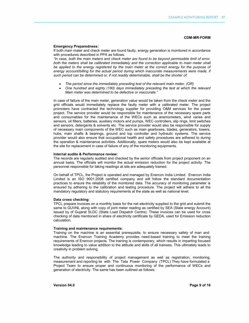
CDM-MR-FORM
Version 04.0 Page 9 of 16
Emergency Preparedness: If both main mater and check meter are found faulty, energy generation is monitored in accordance with procedures described in PPA as follows. “In case, both the main meters and check meter are found to be beyond permissible limit of error, both the meters shall be calibrated immediately and the correction applicable to main meter shall be applied to the energy registered by the main meter at the correct energy for the purpose of energy account/billing for the actual period during which inaccurate measurements were made, if such period can be determined or, if not readily determinable, shall be the shorter of:
The period since the immediately preceding test of the relevant main meter, (OR)
One hundred and eighty (180) days immediately preceding the test at which the relevant Main meter was determined to be defective or inaccurate.”
In case of failure of the main meter, generation value would be taken from the check meter and the grid officials would immediately replace the faulty meter with a calibrated meter. The project promoters have contracted the technology supplier for providing O&M services for the power project. The service provider would be responsible for maintenance of the necessary spare parts and consumables for the maintenance of the WECs such as anemometers, wind vanes and sensors, oil filters, batteries, auxiliary motors and pumps, WEC controllers, slip rings, limit switches and sensors, detergents & solvents etc. The service provider would also be responsible for supply of necessary main components of the WEC such as main gearboxes, blades, generators, towers, hubs, main shafts & bearings, ground and top controller and hydraulic systems. The service provider would also ensure that occupational health and safety procedures are adhered to during the operation & maintenance activities. Additionally, spare meters would also be kept available at the site for replacement in case of failure of any of the monitoring equipments. Internal audits & Performance review: The records are regularly audited and checked by the senior officials from project proponent on an annual basis. The officials will monitor the actual emission reduction for the project activity. The personnel responsible for taking readings at site are adequately trained. On behalf of TPCL, the Project is operated and managed by Enercon India Limited. Enercon India Limited is an ISO 9001:2008 certified company and will follow the standard documentation practices to ensure the reliability of the monitored data. The accuracy of monitoring parameter is ensured by adhering to the calibration and testing procedure. The project will adhere to all the mandatory regulatory and statutory requirements at the state as well as national level. Data cross checking: TPCL prepare invoices on a monthly basis for the net electricity supplied to the grid and submit the same to GUVNL along with copy of joint meter reading as certified by SEA (State energy Account) issued by of Gujarat SLDC (State Load Dispatch Centre). These invoices can be used for cross checking of data mentioned in share of electricity certificate by GEDA, used for Emission reduction calculation.
Training and maintenance requirements: Training on the machine is an essential prerequisite, to ensure necessary safety of man and machine. The Enercon Training Academy provides need-based training to meet the training requirements of Enercon projects. The training is contemporary, which results in imparting focused knowledge leading to value addition to the attitude and skills of all trainees. This ultimately leads to creativity in problem solving. The authority and responsibility of project management as well as registration, monitoring, measurement and reporting lie with The Tata Power Company (TPCL) They have formulated a Project Team to ensure proper and continuous monitoring of the performance of WECs and generation of electricity. The same has been outlined as follows:
EXAMPLE MONITORING REPORT 97
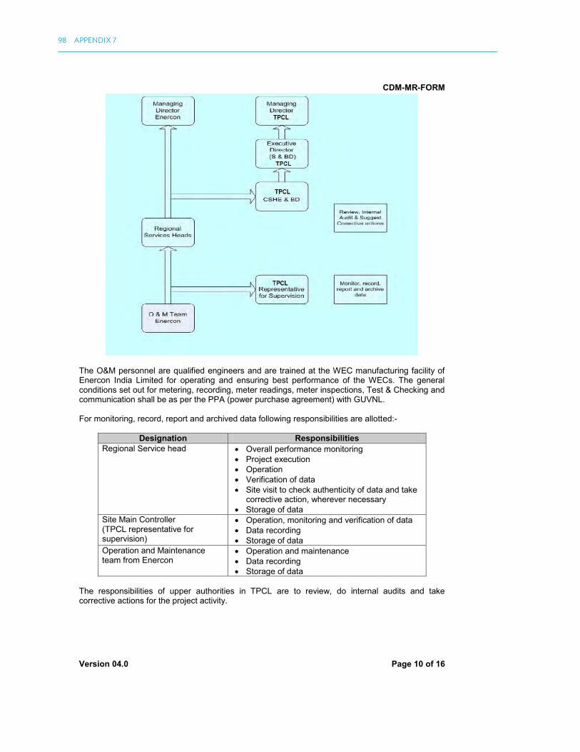
CDM-MR-FORM
Version 04.0 Page 10 of 16
The O&M personnel are qualified engineers and are trained at the WEC manufacturing facility of Enercon India Limited for operating and ensuring best performance of the WECs. The general conditions set out for metering, recording, meter readings, meter inspections, Test & Checking and communication shall be as per the PPA (power purchase agreement) with GUVNL. For monitoring, record, report and archived data following responsibilities are allotted:-
Designation Responsibilities
Regional Service head Overall performance monitoring Project execution Operation Verification of data Site visit to check authenticity of data and take
corrective action, wherever necessary Storage of data
Site Main Controller (TPCL representative for supervision)
Operation, monitoring and verification of data Data recording Storage of data
Operation and Maintenance team from Enercon
Operation and maintenance Data recording Storage of data
The responsibilities of upper authorities in TPCL are to review, do internal audits and take corrective actions for the project activity.
98 APPENDIX 7

CDM-MR-FORM
Version 04.0 Page 11 of 16
SECTION D. Data and parameters
D.1. Data and parameters fixed ex ante or at renewal of crediting period
Data / Parameter: EF OM, y
Unit: tCO2 / MWh Description: Emission factor for the operating margin of the NEWNE Grid Source of data: CEA – CO2 baseline database for Indian power sector Value(s) applied): 1.0049 Purpose of data: Baseline emission calculation Additional comment: CO2 Baseline Database for the Indian Power Sector prepared by Central
Electricity Authority (CEA) Version 5.0 has been referred for the values of operating margin. The operating margin emission factor is calculated as the generation-weighted average CO2 emissions per unit net electricity generation (tCO2/MWh) estimated for year 2006-07, 2007-08 and 2008-09. Value is fixed ex-ante for entire crediting period
Data / Parameter: EF BM, y
Unit: tCO2 / MWh Description: Emission factor for the build margin of the NEWNE Grid Source of data: CEA – CO2 baseline database for Indian power sector Value(s) applied): 0.6752 Purpose of data: Baseline emission calculation Additional comment: CO2 Baseline Database for the Indian Power Sector prepared by Central
Electricity Authority (CEA) Version 5.0 has been referred for the values of build margin and is estimated for year 2008-09. Value is fixed ex-ante for entire crediting period
Data / Parameter: EF y
Unit: tCO2 / MWh Description: Combined Margin CO2 emission factor for NEWNE regional grid Source of data: Estimated figure based on 75% of OM and 25% of BM values. Referred by “CO2
Baseline Database for Indian Power Sector, version 5” published by the Central Electricity Authority, Ministry of Power, Government of India.
Value(s) applied): 0.9224 Purpose of data: Calculation of baseline emission Additional comment: Value is fixed ex-ante for entire crediting period
D.2. Data and parameters monitored
Data / Parameter: EG y
Unit: MWh Description: Net electricity supplied to the grid by the Project Measured/ Calculated / Default:
Measured and Calculated Energy Meters are located at Sadodar (33/220kV) substation. All WECs which are part and not part of the project are connected to these meters. Electricity generation is measured at the substation meters by the representative of
EXAMPLE MONITORING REPORT 99

CDM-MR-FORM
Version 04.0 Page 12 of 16
GETCO (Gujarat Electricity Transmission Company) and O&M service provider (on behalf of individual wind farm owners). Similarly, all WECs which are part of the project activity are also connected to the cluster meters located at the metering yard. The monthly joint meter reading is also recorded from these cluster meters by the representatives of GETCO and O&M service provider. GETCO then distributes share certificates for the particular month after deducting the import from the export.
Source of data: Monthly share certificate issued by GETCO/GEDA Value(s) of monitored parameter:
74,266
Monitoring equipment: Monitoring Equipment: Substation Energy Meters. Serial Number: GJB01470, GJU04175, GJU04176, GJU67589 and KAB11082 Accuracy Class: 0.2S Calibration Frequency: once in 3 years Date of Calibration: 06/09/2013 Validity: 05/09/2016 Monitoring Equipment: Cluster Energy Meters. Serial Number: GJB01605 (feeder no 18), 07025563 (feeder no 18), GJB01604 (feeder no 19) and 07025367 (feeder no 19) Accuracy Class: 0.2S Calibration Frequency: once in 3 years Date of Calibration: 15/07/2013 Validity: 14/07/2016
Measuring/ Reading/ Recording frequency:
Measuring frequency: Continuous Recording frequency: Monthly
Calculation method (if applicable):
Monthly share certificate issued by GETCO/GEDA mentions only net electricity supplied to the grid after deducting import (the quantity of electricity delivered to the project activity from the grid) from Export (the quantity of electricity supplied by the project activity to the grid). The invoicing is done on the basis of this share certificate. EG y = EG export – EG import
QA/QC procedures: Meter calibration shall be conducted once in 3 years by GETCO in accordance with the local calibration standards. Meter accuracy: 0.2s of the meter at respective substations that would be used for the metering of electricity exported. TPCL prepare invoices on monthly basis for the net electricity supplied to the grid and submit the same to GUVNL along with copy of joint meter reading as certified by SEA (State energy Account) issued by of Gujarat SLDC (State Load Dispatch Centre). These invoices can be used for cross checking of data mentioned in share of electricity certificate by GEDA, used for Emission reduction calculation
Purpose of data: Calculation of baseline emission Additional comment: The data (electricity supplied to the grid) will be archived on electronic media as
well as on paper. The archive will be kept for the period up to two years after the completion of the crediting period or the last issuance of CERs for the project activity whichever occurs later.
100 APPENDIX 7

CDM-MR-FORM
Version 04.0 Page 13 of 16
D.3. Implementation of sampling plan
Not Applicable
SECTION E. Calculation of emission reductions or GHG removals by sinks
E.1. Calculation of baseline emissions or baseline net GHG removals by sinks
As per the methodology ACM0002, version 13.0.0, “Baseline emissions include only CO2 emissions from electricity generation in fossil fuel fired power plants that are displaced due to the project activity. The methodology assumes that all project electricity generation above baseline levels would have been generated by existing grid-connected power plants and the addition of new grid-connected power plants. The baseline emissions are to be calculated as follows:
BE y = EG y * EF y........................................... (1) Where, BE y = Baseline emissions in year y (tCO2 / yr)
EG y = Net electricity supplied to the grid by the project
EF y = Combined margin CO2 emission factor for NEWNE regional grid BE y = 74,266 * 0.9224 = 68,503 tCO2
E.2. Calculation of project emissions or actual net GHG removals by sinks
As stated in the registered PDD and as per ACM0002 version 13.0.0, for most renewable energy project activities, PE y = 0.
E.3. Calculation of leakage
As stated in the registered PDD and as per ACM0002 version 13.0.0, the main emissions potentially giving rise to leakage in the context of electric sector projects are emissions arising due to activities such as power plant construction, fuel handling (extraction, processing, and transport). Project participants do not need to consider these emission sources as leakage in applying this methodology. Therefore no leakage is taken into consideration. Also no credits on account of reducing these emissions below the level of the baseline scenario are claimed. LE y = 0.
E.4. Summary of calculation of emission reductions or net anthropogenic GHG removals by sinks
Item
Baseline emissions or baseline net
GHG removalsby sinks(t CO2e)
Project emissions or
actual net GHG removals by
sinks(t CO2e)
Leakage(t CO2e)
Emission reductions or
net anthropogenic GHG removals
by sinks(t CO2e)
Total 68,503 0 0 68,503
E.5. Comparison of actual emission reductions or net anthropogenic GHG removals by sinks with estimates in registered PDD
ItemValues estimated in ex-ante calculation
of registered PDDActual values achieved during this
monitoring period
EXAMPLE MONITORING REPORT 101

CDM-MR-FORM
Version 04.0 Page 14 of 16
ItemValues estimated in ex-ante calculation
of registered PDDActual values achieved during this
monitoring period
Emission reductions or GHG removals by sinks (t CO2e)
96,8214
68,503
E.6. Remarks on difference from estimated value in registered PDD
As per the registered PDD, the annual average emission reductions estimated were 96,821 tCO2e/annum. During the current monitoring period from 01/01/2014 to 31/12/2014, which accounts to 365 days, hence the pro-rata emission reduction stands to 96,821 tCO2e. The actual emission reductions achieved is 68,503 tCO2e which is 29.25% lesser than the value estimated in the PDD. This is due to lower PLF observed at the project site during the monitoring period.
E.7. Actual emission reductions or net anthropogenic GHG removals by sinks during the first commitment period and the period from 1 January 2013 onwards
ItemActual values achieved up to
31 December 2012Actual values achieved from
1 January 2013 onwards
Emission reductions or GHG removals by sinks (t CO2e)
0 68,503
- - - - -
4 The current monitoring period is for 365 days. Accordingly the estimated emission reduction in-line with the registered
PDD input values is calculated for 365 days.
102 APPENDIX 7

CDM-MR-FORM
Version 04.0 Page 15 of 16
Appendix 1. Contact information of project participants and responsible persons/ entities
Project participant and/or responsible person/ entity
Project participant Responsible person/ entity for completing the CDM-MR-FORM
Organization name The Tata Power Company Limited, India Street/P.O. Box 34, Sant Tukaram Road, Carnac Bunder Building Business Development Department, Corporate Center’A’ Block City Mumbai State/Region Maharashtra Postcode 400009 Country India Telephone +91 22 67171207 Fax +91 22 66658626 E-mail [email protected] Website www.tatapower.com Contact person Rahul Shah Title Vice President Business Development Salutation Mr. Last name Shah Middle name - First name Rahul Department Business Development Mobile +91 9223301139 Direct fax +91 22 66658626 Direct tel. +91 22 67171207 Personal e-mail [email protected]
EXAMPLE MONITORING REPORT 103
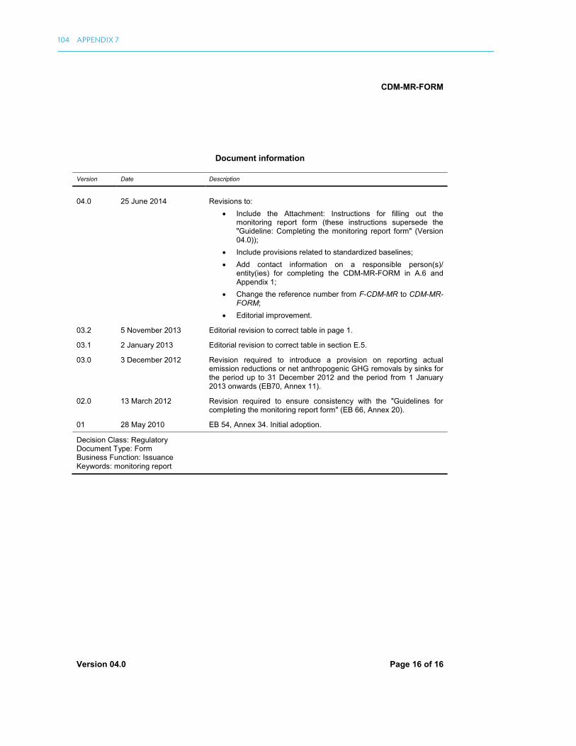
CDM-MR-FORM
Version 04.0 Page 16 of 16
Document information
Version Date Description
04.0 25 June 2014 Revisions to: Include the Attachment: Instructions for filling out the
monitoring report form (these instructions supersede the "Guideline: Completing the monitoring report form" (Version 04.0));
Include provisions related to standardized baselines; Add contact information on a responsible person(s)/
entity(ies) for completing the CDM-MR-FORM in A.6 and Appendix 1;
Change the reference number from F-CDM-MR to CDM-MR-FORM;
Editorial improvement.
03.2 5 November 2013 Editorial revision to correct table in page 1.
03.1 2 January 2013 Editorial revision to correct table in section E.5.
03.0 3 December 2012 Revision required to introduce a provision on reporting actual emission reductions or net anthropogenic GHG removals by sinks for the period up to 31 December 2012 and the period from 1 January 2013 onwards (EB70, Annex 11).
02.0 13 March 2012 Revision required to ensure consistency with the "Guidelines for completing the monitoring report form" (EB 66, Annex 20).
01 28 May 2010 EB 54, Annex 34. Initial adoption.
Decision Class: Regulatory Document Type: Form Business Function: Issuance Keywords: monitoring report
104 APPENDIX 7

ASIAN DEVELOPMENT BANK6 ADB Avenue, Mandaluyong City1550 Metro Manila, Philippineswww.adb.org
Monitoring, Reporting, and Verification Manual for Clean Development Mechanism Projects
The Clean Development Mechanism (CDM), a market mechanism under the Kyoto Protocol, has been successful in supporting mitigation actions through carbon inance. With nearly 7,700 projects and 290 Program of Activities registered by the CDM Executive Board, the CDM allows GHG emission reduction projects in developing countries to generate Certiied Emission Reductions which can be used to ofset mandatory or voluntary emission reduction targets. It however requires a robust monitoring, reporting, and veriication (MRV) to ensure social and environmental integrity of such projects and the emissions reductions thereof. This MRV manual is intended to assist CDM project developers in understanding and managing the MRV requirements and process of their CDM projects in a simple step-by-step manner with the help of real examples and practical tips. While this MRV manual has been developed primarily to assist CDM project developers, it also aspires to be of help for projects participating in other existing and emerging market mechanisms. These may include bilateral mechanisms; voluntary carbon markets; regional, national, and subnational carbon markets; and any of the cooperative approaches and new market mechanism for the post-2020 carbon markets consequent to the Paris Agreement adopted at COP21 in December 2015. As carbon markets in the region evolve beyond CDM, there is a strong need to maintain and further build institutional capacities to ensure growth and enhanced efectivity of carbon markets –
and this MRV manual is an efort in that direction.
About the Asian Development Bank
ADB’s vision is an Asia and Pacific region free of poverty. Its mission is to help its developing member countries reduce poverty and improve the quality of life of their people. Despite the region’s many successes, it remains home to the majority of the world’s poor. ADB is committed to reducing poverty through inclusive economic growth, environmentally sustainable growth, and regional integration.
Based in Manila, ADB is owned by 67 members, including 48 from the region. Its main instruments for helping its developing member countries are policy dialogue, loans, equity investments, guarantees, grants,
and technical assistance.


