mon train206 appendices - US EPA · after the proposal date PAI process units is after the proposal...
115
Appendix A Compliance Timeline
Transcript of mon train206 appendices - US EPA · after the proposal date PAI process units is after the proposal...

Appendix A
Compliance Timeline

[This page intentionally left blank.]

Init
ial
No
tific
atio
n(§
63.2
515(
b))
Co
mp
lianc
eD
ate
(§63
.244
5)
Init
ial
No
tific
atio
no
f C
omp
lianc
eS
tatu
s (N
OC
S)
(§63
.252
0(d
))
Pre
com
plia
nce
Rep
ort
(§63
.252
0(c)
)
Co
mp
lianc
eR
epo
rts
(§63
.252
0(e)
)
Site
-Sp
ecif
ic
Tes
t P
lan
and
No
tific
atio
n o
fP
lan
ned
P
erfo
rman
ceT
est
(§63
.251
5(c)
)
Eff
ecti
ve d
ate
No
vem
ber
10,
20
03
Init
ial
No
tific
atio
n
(§63
.251
5(b
))
Co
mp
lianc
e D
ate
(§63
.244
5)
No
tific
atio
n
of
Com
plia
nce
Sta
tus
(NO
CS
)(§
63.2
520(
d))
Pre
com
plia
nce
Rep
ort
(§
63.2
520(
c))
Co
mp
lianc
e R
epo
rts
(§63
.252
0(e)
)
Site
-Sp
ecif
ic
Tes
t P
lan
an
d
No
tific
atio
n o
f P
lan
ned
P
erfo
rman
ce
Tes
t (§
63.2
515(
c))
Exi
stin
g
Au
gu
st 3
1,A
ug
ust
31,
sou
rces
–
2007
2007
init
ial s
tart
up
b
efo
re A
pri
l 4,
2002
(R
ule
M
arch
9,
May
6,
Mar
ch 9
,M
ay 6
,p
rop
osa
l dat
e)
2004
20
0620
0420
06
60 d
ays
60 d
ays
and
and
bef
ore
bef
ore
ever
y 6
ever
y 6
No
vem
ber
10,
p
erfo
rman
ceN
ove
mb
er 1
0,p
erfo
rman
ceA
pri
l 7,
mo
nth
sA
pri
l 7,
mo
nth
s20
06
test
2006
test
2007
th
erea
fter
2007
ther
eaft
er
New
so
urc
es--
Mar
ch 9
, W
ith t
he
New
so
urc
es--
Mar
ch 9
,W
ith t
he
No
vem
ber
10,
60
day
sN
ove
mb
er 1
0,60
day
s 15
0 d
ays
Fir
st A
ug
31o
r F
eb 2
815
0 d
ays
Fir
st A
ug
31o
r F
eb 2
8in
itia
l sta
rtu
p
2004
or
app
licat
ion
init
ial s
tart
up
2004
or
app
licat
ion
2003
or
bef
ore
2003
or
bef
ore
afte
r fo
llow
ing
the
end
afte
rfo
llow
ing
the
end
afte
r 12
0 d
ays
for
app
rova
laf
ter
120
day
s fo
r ap
pro
val
up
on
init
ial
per
form
ance
up
on
init
ial
per
form
ance
the
of
the
com
plia
nce
the
of
the
com
plia
nce
Ap
ril 4
, 200
2 af
ter
of
Ap
ril 4
,200
2af
ter
of
star
tup
, te
stst
artu
p,
test
Co
mp
lian
ce
per
iod
th
at o
ccu
rsC
om
plia
nce
per
iod
th
at o
ccu
rs(R
ule
in
itia
l co
nst
ruct
ion
(Ru
lein
itia
lco
nst
ruct
ion
wh
ich
ever
d
ate
mo
re t
han
6 m
on
ths
wh
ich
ever
dat
em
ore
th
an 6
mo
nth
sp
rop
osa
l st
artu
p,
or
pro
po
sal
star
tup
,o
ris
late
r af
ter
the
com
plia
nce
is la
ter
afte
r th
e co
mp
lian
ced
ate)
w
hic
hev
er
reco
nst
ruct
ion
d
ate,
an
d e
very
d
ate)
wh
ich
ever
reco
nst
ruct
ion
dat
e, a
nd
ever
yis
late
ris
late
r6
mo
nth
s th
erea
fter
6 m
on
ths
ther
eaft
er

[This page intentionally left blank.]

Appendix B
# Tabular Summaries of Emission Standards and Monitoring Parameters for Subpart FFFF
# Tables Comparing Requirements in Subparts GGG, MMM, and FFFF

[This page intentionally left blank.]

Table 1. Standards for Process Vents
For each ... And ... The control optionsa are ...
Group 1 continuous
process ventb
Group 2 continuous
process vent
N/A
For each halogenated
vent streamc that is
controlled using a
The TRE is 5.0 at
an existing source or
8.0 at a new source
The TRE is >5.0 at
an existing source of
>8.0 at a new source
Process with Group 1 N/A
batch process ventse
• (except a flare) that reduces organic HAP by 98
percent, or
• (except a flare) that reduces organic HAP to 20
• •
existing source or >5.0 at a new source
•
halogen HAPd:
•
• 0.45 kg/hr, or
•
•
• 0.45 kg/hr, or
•
§63.993 of subpart SS
None
• devices that reduces organic HAP by 98 percent,
or
• 95
percent, or
•
organic HAP to
vents in the process by 98 percent using control
devices or
combustion device
Use any control device or combination of devices
Use any control device or combination of devices
ppmv as organic HAP or TOC, or
Use a flare, or
Use a recovery device to maintain TRE >1.9 at an
Use a halogen reduction device after the
combustion device to reduce hydrogen halide and
By 99 percent by weight, or
To
To 20 ppmv, or
Use a halogen reduction device before the
combustion device to reduce the halogen atom mass
emission rate to:
20 ppmv
Monitor control device parameters as specified in
Use any control device or combination of control
Use any recovery device or combination of
recovery devices that reduces organic HAP by
For any subset of vents in the process, use a flare or
use any combination of control devices to reduce
20 ppmv as total organic HAP or
TOC, and reduce collective emissions from other
95 percent using recovery devices
1

c
Table 1. Standards for Process Vents (continued)
For each ... And ... The control optionsa are ...
Process with Group 1 For collective • Use a halogen reduction device after the batch process ventse halogenated vent combustion device to reduce overall hydrogen (continued) streams that are halide and halogen HAP:
controlled using a • By 99 percent by weight, or
combustion device • To 0.45 kg/hr, or
• To 20 ppmv, or
• Use a halogen reduction device before the
combustion device to reduce the overall halogen
atom mass emission rate to
• 0.45 kg/hr, or
• 20 ppmv
Process with Group 2 N/A None batch process vents
Process with N/A • Use a control device or combination of control uncontrolled hydrogen devices to reduce collective hydrogen halide and halide and halogen halogen HAP: HAP emissions from • By 99 percent by weight, or process vents 1,000 • To 20 ppmv lb/yr
Process at a new N/A Reduce overall PM HAP emissions by 97 percent source with uncontrolled PM HAP emissions from process vents 400 lb/yr
a Each control option also includes requirements for closed-vent systems (as specified in §63.983),
except for the recovery device option for continuous process vents. b A Group 1 continuous process vent means a continuous process vent with a TRE 1.9 at an existing
source and 5.0 at a new source. A halogenated vent stream means a vent stream determined to have a mass emission rate of halogen atoms contained in organic compounds of 0.45 kg/hr.
d Hydrogen halide and halogen HAP means hydrogen chloride, hydrogen fluoride, and chlorine. e All of the batch process vents in a process are Group 1 batch process vents if the collective organic
HAP emissions from all of the batch process vents are 10,000 lb/yr at an existing source or 3,000
lb/yr at a new source.
2

c
Table 2. Standards for Storage Tanks
Storing material with a maximum true vapor
For each … pressure … The control optionsa are …
Group 1 storage 76.6 kPa • Use any combination of control devices (except a flare) that
tank with reduces total HAP emissions by 95 percent by weightd, or
nonhalogenated • Use any combination of control devices (except a flare) that
vent streamb,c reduces total HAP emissions to 20 ppmv as total organic
HAP or TOC and 20 ppmv of hydrogen halide and
halogens,d,e or
• Use a flared, or
• Vent to a process or fuel gas system, or
• Implement vapor balancing between the storage tank and the
rail car or tank truck from which the storage tank is filled
<76.6 kPa • Any of the options for a storage tank storing material with a
maximum true vapor pressure 76.6 kPa, or
• Equip the storage tank with either an internal floating roof or
an external floating roof
Group 1 storage Of any value • Any of the options for Group 1 storage tanks with
tank with nonhalogenated vent streams, and
halogenated vent • If the halogenated vent stream is combusted:
stream • Use a halogen reduction device after the combustion
device to reduce hydrogen halide and halogen HAP by
99 percent by weight, to 0.45 kg/hr, or
• Use a halogen reduction device before the combustion
device to reduce the halogen atom mass emission rate to
0.45 kg/hr or to 20 ppmv
Group 2 storage N/A None tank
a Each control option includes requirements for a closed-vent system (as specified in §63.983), except
the options to vent to a process or fuel gas system or to use a floating roof. b A Group 1 storage tank means a storage tank with a capacity 10,000 gallons storing material with a
maximum true vapor pressure 6.9 kPa at an existing source or 0.69 kPa at a new source.
A halogenated vent stream means a vent stream determined to have a mass emission rate of halogen
atoms contained in organic compounds of 0.45 kg/hr.d The requirements do not apply during periods of planned routine maintenance of the control device
up to 240 hr/yr (360 hr/yr if extension request is approved by Administrator). e Hydrogen halide and halogen HAP means hydrogen chloride, hydrogen fluoride, and chlorine..
3

Table 3. APCD Monitoring Parameters
Section in
Subpart SS
and Subpart
APCD Parameters to Monitor FFFF
Halogen scrubbers • §63.994(c)(1)
• §63.2450(k)(3)
•
effluent
Absorbersa • §63.990(c)(1)
and or
• §63.993(c)(1)
specific gravities of the saturated scrubbing fluid and the fresh
scrubbing fluid is <0.02 specific gravity units
Condensera §63.990(c)(2)
side) or
§63.993(c)(2)
Regenerative carbon For each regeneration cycle: §63.990(c)(3)
adsorbera • or
• §63.993(c)(3)
Flares §63.987(c)
§63.988(c)(1)
the firebox
Catalytic incinerator • §63.988(c)(2)
after the catalyst bed, or or
• §63.2450(k)(4)
catalyst activity annually
Process heaters and boilers §63.988(c)(3)
where vent gases are not
introduced with the
heat input capacity is not
44 MW
Other devices §63.995(c)
Continuously monitor scrubber inlet liquid flow, and
Measure or determine inlet gas flow rate, and
Continuously monitor pH or caustic strength of the scrubber
Continuously monitor liquid temperature and specific gravity,
Continuously monitor organic concentration if difference in
Continuously monitor temperature of condenser outlet (product
Monitor total regeneration stream mass or volumetric flow
Monitor carbon bed temperature after each regeneration and
within 15 minutes of the end of each cooling cycle
Continuously monitor for presence of pilot flame
Thermal incinerator Continuously monitor temperature immediately downstream of
Continuously monitor temperature immediately before and
Continuously monitor temperature before the bed and check
Continuously monitor temperature of gases exiting the
combustion chamber
primary fuel or the design
Request approval of planned monitoring
a The specified parameters also apply if the absorber, condenser, or regenerative carbon adsorber is used as a
final recovery device for continuous process vents.
4

Requirements
Parameter Subpart GGG Subpart MMM Subpart FFFF
Affected source • Any process that produces • Any process that produces • Any process that produces
a PAI or integral
• not subject to another
• MACT
subject to another MACT affected source other •
•
products subject to another MACT define process boundaries
• •
products
pesticide products
New affected • An affected source for • • An affected source for
source which construction or except the reconstruction which construction or
cutoff date for dedicated
after the proposal date PAI process units is after the proposal date
• A dedicated PMPU with 9/20/02 • A dedicated MCPU with
HAP PTE > 10/25 tpy for HAP PTE > 10/25 tpy for
which construction which construction or
proposal date or after the proposal date
after 10/21/99
Dedicated process unit place and designed and exclusively for one process
product for a continuous operated to produce only a
single product (or co- shared)
products)
HAP subject to All • Organic HAP • Organic HAP
control • HCl/Cl2 • HCl/Cl2/HF
• •
sources)
Group 1 Group 1
used to describe
subject to control
Table 4. Comparison of Applicability in Subparts GGG, MMM, and FFFF
a pharmaceutical product an organic chemical and is
Includes all isolated intermediate
intermediates that are not Source may include in the
Concept of isolated
Applies to formulation of intermediates that are not intermediate is used to
Applies to formulation of Applies to formulation of
PAI, but not formulation of
Same as for subpart GGG
reconstruction commenced reconstruction commenced
commenced after the reconstruction commenced
reconstruction commenced
Equipment used to Equipment that is fixed in Equipment that is used
manufacture the same
(but storage tanks may be
period of at least 6 months
PM HAP (only for bag PM HAP (only from new
dumps and product dryers)
Terminology Affected streams
emission streams
5

Requirements
Parameter Subpart GGG Subpart MMM Subpart FFFF
Threshold for • • •
control at existing HAP/yr/process organic HAP organic HAP for BPV
source • • •
and Cl2 •
HCl and Cl2 generated by Cl2, and HF
devices)
•
Threshold for > 0.9 Mg HAP/yr/facility •
control at new HAP for BPV
source •
•
Cl2, and HF
•
Control • Reduce to less than • •
threshold
options for • • •
existing source (or grandfathered lower
levels) per process •
• • 2 per
vents per process process recovery device
• 95% for HCl/Cl2/HF • •
• HCl/Cl2/HF generated by
devices •
• Outlet concentration
< 0.45 kg/hr
• • 2/HF
•
Control • Reduce to less than
threshold
new source •
vents per process
•
except the thresholds are lower
process
• 2
• Outlet concentration if uncontrolled is < 191
Mg/yr
• • 2
if uncontrolled is > 191
Mg/yr
•
•
•
Table 5. Comparison of Process Vent Standards in Subparts GGG, MMM, and FFFF
> 0.9 Mg > 0.15 Mg/yr/process of > 10,000 lb/yr/process of
> 1.8 Mg HAP/yr/facility > 6.8 Mg/yr/process of HCl TRE < 5.0 for CPV
(includes amount of > 1,000 lb/yr/process of HCl,
combustion control
> 0.01 gr/dscf for PM HAP
Same as for existing source > 3,000 lb/yr/process of organic
TRI < 8.0 for CPV
> 1,000 lb/yr/process of HCl,
> 400 lb/yr/process of PM HAP
> 98% for organic HAP > 95% for sum of organic HAP
requirement from “large” vents from BPV if recovered
> 98% for “large” vents > 90% for sum of organic > 98% for sum of organic HAP
HAP from all other vents from BPV if controlled
> 98% for CPV with TRE < 1.9,
93% for sum of all other 94% for sum of HCl/Cl or maintain TRE > 1.9 with a
Outlet concentration limits > 99% or < 0.45 kg/hr for
generated in combustion < 0.01 gr/dscf for PM HAP
Specific devices combustion control, or reduce
halogen atom mass rate to
limits
Specific devices > 99% for sum of HCl/Cl
from the process
Outlet concentration limits
requirements for
> 98% for sum of all
> 98% for sum of organic Same as for existing source
HAP from all vents per
> 94% for sum of HCl/Cl
limits
Specific devices > 99% for sum of HCl/Cl
< 0.01 gr/dscf for PM HAP
Outlet concentration limits
Specific devices
6

Requirements
Parameter Subpart GGG Subpart MMM Subpart FFFF
Threshold for
control at existing capacity > 38 m3 capacity > 75 m3 capacity > 10,000 gal
source
Threshold for •
control at new and capacity > 10,000 gal
source 16.5 kPa, and
capacity > 40 m3
Control • 3 • •
• • •
options for both 90%) if > 75 m3 • •
new and existing • • Vapor balance • Vapor balance
sources • • •
• Vapor balance •
• system
Table 6. Comparison of Storage Tank Standards in Subparts GGG, MMM, and FFFF
MTVP > 13.1 kPa, and MTVP > 3.45 kPa, and MTVP > 6.9 kPa, and
Same as for existing source Same as for existing source, MTVP > 0.69 kPa, and
• MTVP >
> 90% if < 75 m > 95% > 95%
requirement > 95% (or grandfathered Outlet concentration limits Outlet concentration limits
Floating roof Floating roof if < 76.6 kPa
Outlet concentration limits
Floating roof Specific APCD Specific APCD
Return to process or fuel gas
Specific APCD
7

Requirements
Parameter Subpart GGG Subpart MMM Subpart FFFF
Threshold for
control at existing
source wastewater) with
• Process wastewater at POD
with
used to control PAI process
• PSHAP > of total PSHAP and SHAP
• SHAP
HAP
Mg/yr • > PSHAP and SHAP
• Table 9 HAP
•
> 5.3 Mg of HON Table 9
HAP per discharge event
Threshold for •
control at new and
source •
of any individual HON
Table 8 HAP
Maintenance wastewater
except as noted above
wastewater
Definition of process
cleaning wastewater states that wastewater states that it wastewater states that
operations includes water used to clean
cleaning operations as part of
wastewater batch operations is not
Table 7. Comparison of Wastewater Standards in Subparts GGG, MMM, and FFFF
Wastewater at POD
(excluding maintenance
Process wastewater at POD
or effluent from a scrubber
• > 1 pm and > 1,000 ppmw
1,300 ppmw and emissions with
> 0.25 Mg/yr • > 10 pm and > 1,000 • > 30,000 ppmw and > 1 tpy
Total PSHAP and SHAP ppmw of HON Table 9
> 5,200 ppmw and > 0.25 • > 10,000 ppmw total
10,000 ppmw of HON
Scrubber effluent if it
contains PSHAP removed Each maintenance
from affected PV stream wastewater stream with
Same as for existing source Same as for existing source Same as for existing source,
Process wastewater with
> 0.02 pm and > 10 ppmw
Exempt from all wastewater Subject only to requirements Subject only to requirements
requirements except those for maintenance wastewater, for maintenance wastewater
specific to maintenance
Wastewater from Definition of maintenance Definition of maintenance
wastewater from cleaning wastewater from routine
operations is not maintenance process equipment
maintenance wastewater
8

Table 7. Comparison of Wastewater Standards in Subparts GGG, MMM, and FFFF
(continued)
Requirements
Parameter Subpart GGG Subpart MMM Subpart FFFF
options for
existing source
• • •
•
• •
• •
SHAP HAP in wastewater sent to
SHAP in wastewater sent to
> 90% for SHAP
• Other •
•
except if SHAP > 110,000
options for new PAI process units at an
sources 1
Mg/yr of HON Table 9 HAP,
reduce SHAP by > 99% or
suppression
waste
at new and
existing sources
•
except: Appendix C in this
• no option to use a fixed roof workbook
on a wastewater tank that is •
discharged to offsite
sparging
• no option to vent sewer sludge unit need not be
lines that are water sealed at covered if the wastewater
the drains and first
PSHAP, and SHAP losses
prior to the activated sludge
unit
Treatment
requirement
Nonbiological PSHAP: < 50 ppmw or Design steam stripper Same as subpart MMM
> 99% > 99% or > Fr
SHAP: < 520 ppmw or < 50 ppmw
> 90% • AMR > RMR
Biological Enhanced biotreatment for • > 95% for all HON Table 9 Same as subpart MMM
• > 95% for all PSHAP and treatment unit
• AMR > RMR
treatment unit
• > 99% for PSHAP and
Offsite treatment Same as subpart GGG Same as subpart GGG
RCRA-permitted unit
Treatment Same as for existing sources Same as for existing sources, Same as for existing sources,
requirement except if wastewater from all except lower threshold means
ppmw and total PSHAP and more streams may be subject
SHAP from the PMPU is > affected source has > 2,100 to control requirements
Mg/yr, then must either
then must reduce by > 99% or
use RCRA-permitted unit use RCRA-permitted unit
Emission Same as for subpart FFFF
requirements for
management units
Same as for subpart FFFF, See Flowcharts 3 and 4 of
In addition, for wastewater
used for heating, treatment
by exothermic reaction, or biotreatment, the offsite
WMUs up to the activated
contains < 50 ppmw
downstream junction box
are determined to be < 5%
9

Requirements
Parameter Subpart GGG Subpart MMM Subpart FFFF
Threshold for
control at existing HAP service > 300 hr/yr GGG
source
•
existing sources • GGG
connectors in gas/vapor and light
subpart GGG, except:
if few leakers) •
• valves in gas/vapor and light
if few leakers)
connectors is different
•
percentage leak
•
•
•
• no continuous process vents.
of liquids dripping • higher leak definition for
•
• •
connectors
connections •
•
• no pressure testing option
• •
replace rupture disk for PRVs in any process
gas and vapor service
• sensory indication of leak or
connectors, and agitators in heavy liquid service, PRVs in liquid service, and
•
•
new sources sources except the subpart TT option is not
allowed
Table 8. Comparison of Equipment Leak Standards in Subparts GGG, MMM, and FFFF
Components that are in organic Same as for subpart Same as for subpart GGG
Requirements for Implement LDAR program with Same as for subpart Implement the subpart UU
Annual M21 monitoring for LDAR program for any
processes, which is same as
liquid service (or skip monitoring
skip monitoring frequency for
Monthly M21 monitoring for
liquid service (or skip monitoring
quality improvement program
is required for pumps if “high”
Quarterly M21 monitoring for
pumps/agitators in light liquid
service (monthly for pumps if
high number of leakers)
monthly baseline monitoring
for pumps and agitators
Implement the subpart TT LDAR
program for processes that have
Weekly sensory inspection of
pumps/agitators for indications Same as subpart UU except:
Cap open-ended valves and lines pumps and valves
Closed purge, closed loop, or only sensory monitoring for
closed-vent system for sampling
different skip monitoring
Seal system requirements for options for pumps
compressors
M21 monitoring after releases or Implement the CAR LDAR for
M21 monitoring within 5 days of
eliminate the indications of a
leak for pumps, valves,
instrumentation systems
Pressure test process as an
alternative to above monitoring
Repair leaks within 15 days
Requirements for Same as for existing sources Same as for existing Same as for existing sources
10

MMM, and FFFF
Requirements
Parameter Subpart GGG Subpart MMM Subpart FFFF
Threshold for control at new None None Loading rack for tank trucks and/or
and existing sources /yr of
> 1.5 psia
None None •
for new and existing sources •
•
or
•
•
•
•
•
• 2/HF by > 99%, to
•
Table 9. Comparison of Transfer Operation Standards in Subparts GGG,
railcars that loads > 0.65 million
material with an average partial pressure
Control requirement options For organic HAP emissions
> 98% reductions in organic HAP, or
< 20 ppmv TOC or total organic HAP,
use flare, or
route to fuel gas system, or
route to process, or
vapor balance
For halogenated emission streams that
are controlled with combustion
reduce total HCl/Cl
< 0.45 kg/hr, or to < 20 ppmv, or
reduce halogen atom mass rate to
< 0.45 kg/hr or < 20 ppmv
11

MMM, and FFFF
Requirements
Parameter Subpart GGG Subpart MMM Subpart FFFF
controlled with
APCD
except:
•
because no distinction
between BPV and CPV
•
depressurization
•
as specified in §63.1257 of
subpart GGG
•
average flowrate for
those that are subject to
98% control
•
designate as Group 1
•
designate as Group 1 (under
certain conditions)
•
HCl/Cl2
BPV and CPV
• Do not need to calculate
transfer operations, storage
tanks, or wastewater (except
profile)
•
•
when APCD is a condenser
•
design evaluation for
•
• calculations as necessary to
show process-based percent
reduction for BPV
•
specified in subpart SS (or
subpart G for wastewater
vents) or conduct design
evaluation as specified in
§63.1257, except as follows:
•
worst-case conditions for
BPV
•
specified in §63.1257 to
produces the worst-case
conditions
•
CVS
Table 10. Comparison of Initial Compliance Requirements in Subparts GGG,
Demonstration for
vent streams
Same as for subpart FFFF,
No TRE calculation
More calculation options
are specified for emission
from heating and
Conduct performance tests
Calculate flow-weighted
“large” vents to determine
Same as for subpart GGG Calculate TRE for CPV or
Calculate uncontrolled
emissions from BPV or
Calculate uncontrolled
/HF emissions from
uncontrolled emissions from
as they affect an emissions
Determine controlled
emissions
using specified equations
conduct performance test or
“small” APCD
conduct performance test
for “large” APCD
Conduct performance test as
determine compliance under
develop emissions profile as
determine the situation that
Initial M21 inspection of
12
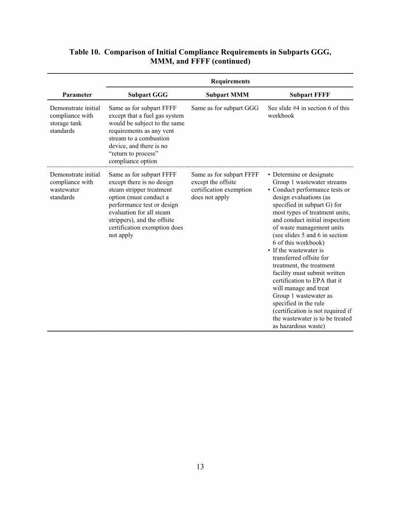
MMM, and FFFF (continued)
Requirements
Parameter Subpart GGG Subpart MMM Subpart FFFF
See slide #4 in section 6 of this
except that a fuel gas system workbook
storage tank
standards
device, and there is no
“return to process”
•
except there is no design except the offsite
wastewater •
standards does not apply design evaluations (as
specified in subpart G) for
evaluation for all steam
strippers), and the offsite and conduct initial inspection
not apply (see slides 5 and 6 in section
6 of this workbook)
• If the wastewater is
transferred offsite for
certification to EPA that it
Group 1 wastewater as
specified in the rule
(certification is not required if
the wastewater is to be treated
as hazardous waste)
Table 10. Comparison of Initial Compliance Requirements in Subparts GGG,
Demonstrate initial Same as for subpart FFFF Same as for subpart GGG
compliance with
would be subject to the same
requirements as any vent
stream to a combustion
compliance option
Demonstrate initial Same as for subpart FFFF Same as for subpart FFFF Determine or designate
compliance with Group 1 wastewater streams
steam stripper treatment certification exemption Conduct performance tests or
option (must conduct a
performance test or design
most types of treatment units,
certification exemption does of waste management units
treatment, the treatment
facility must submit written
will manage and treat
13

MMM, and FFFF
Requirements
Parameter Subpart GGG Subpart MMM Subpart FFFF
•
except: except does not include
• periodic verification applies periodic verification that the
ongoing even if APCD is not used for APCD is working properly
•
percent reduction •
standard or outlet
concentration and pressure drop is an
alternative to liquid flow • If the APCD is not used to control
•
check for bed poisoning
•
for nonregenerative carbon
adsorbers
• in this Appendix and section 7 of
rule does not include the option the presentation slides)
• If APCD is used to control
procedures in subpart G, which
•
but subpart G does not address
• •
for scrubber liquid flow and •
•
devices for BPV)
• •
•
periods of PRM of CCCDs •
the 3 test runs
•
•
different operating conditions
(i.e., batch)
•
design evaluation
Table 11. Comparison of Ongoing Compliance Requirements in Subparts GGG,
Parameter Same as for subpart FFFF, Same as for subpart GGG If APCD is used for BPV and
monitoring to inlet HAP load is < 1 tpy:
demonstrate requirements for CCCDs
compliance with a any BPV If APCD is not used for BPV or
for scrubbers, caustic strength the inlet HAP load is > 1 tpy:
is not a specified parameter, continuous parameter monitoring
is required
limits
for regenerative carbon wastewater emissions, follow
adsorbers, must conduct annual subpart SS requirements
regarding parameters to monitor,
this rule specifies requirements accuracy requirements for some
monitoring devices, and
calibration frequency (see Table 3
for catalytic incinerators, this
to monitor temperature before
the catalyst bed and check wastewater emissions, follow
catalyst activity
slight differences in accuracy are similar to those in subpart SS,
requirements for temperature
monitoring devices the same group of APCDs
includes accuracy requirements Data averaging period options:
daily for any vent stream
pressure drop monitoring operating block (only allowed
requires annual calibration of If initial compliance is based on a
all monitoring devices performance test, establish
includes exemptions for parameters:
based on measurements during
may supplement with
engineering assessments or
manufacturer’s
recommendations
may set separate levels for
For a small control device, may
set operating limits as part of
14

MMM, and FFFF (continued)
Requirements
Parameter Subpart GGG Subpart MMM Subpart FFFF
Alternative
standard
S
e
•
•
xcept:
PS 8
devices) as an alternative to
concentrations for
except:
•
HCl/Cl2
•
alternative to correcting
concentrations for
•
scrubbers used to
control HCl/Cl2 that is
generated by
•
•
•
•
•
and/or HCl/Cl2
used to control HCl/Cl2/HF
according to applicable PS in 40
CFR part 60 appendix B (and
appendix F, procedure 1 for
HCl/Cl2/HF if applicable PS has
in accordance with §63.8(e) and
•
•
CPMS in §63.999(c)(6)(1) of
subpart SS, except data only
periods in an hour when
•
concentrations to account for
• •
•
•
proper operation
Table 11. Comparison of Ongoing Compliance Requirements in Subparts GGG,
ame as for subpart FFFF
subpart GGG does not require
compliance with appendix F,
procedure 1 for CEMS meeting
subpart GGG includes two
parameter monitoring options
(one for combustion devices
and one for noncombustion
correcting measured
supplemental gases
Same as for subpart GGG
subpart MMM does not
specify requirements for
CEMS
subpart MMM includes
a parameter monitoring
supplemental gases only
for combustion devices
subpart MMM does not
include the parameter
monitoring option for
combustion devices
Continuously monitor TOC
/HF (or monitor
scrubber parameters for scrubber
generated by combustion control)
Install, operate, and maintain
CPMS meeting PS 8)
Submit monitoring plan for
CEMS other than FTIR meeting
PS 15 that is used to monitor
not yet been promulgated
Calibration gas and reporting unit
requirements specified in
§63.2450(j)(2)
Conduct performance evaluation
include results in NOCS
Averaging period must be daily
Valid data requirements are
consistent with requirements for
required for 2 of the 15-minute
calibration, QA, or maintenance
are performed
Must correct measured
supplemental gases
Wastewater
treatment units
For biological treatment units,
monitor TSS, BOD, and
Same as for subpart FFFF For steam strippers, continuously
monitor steam flow rate,
biomass concentration using
methods approved by the
permitting authority and at a
frequency approved by the
permitting authority
For other treatment units,
request approval to monitor
appropriate parameters that
demonstrate proper operation
wastewater feed temperature, and
wastewater mass flow rate
For other treatment units, request
approval to monitor appropriate
parameters that demonstrate
15

Table 11. Comparison of Ongoing Compliance Requirements in Subparts GGG,
MMM, and FFFF (continued)
Requirements
Parameter Subpart GGG Subpart MMM Subpart FFFF
•
unit inspections inspections for leaks, control
work practices
•
for EFR used on wastewater tanks
and oil-water separators
•
enclosures
•
and vapor does not have the provisions in •
subpart SS that differ from inspections of unsafe-to-
inspections subpart G piping
•
is constructed of ductwork
•
designated as unsafe- or difficult-
to-inspect
•
subpart SS are not in subpart G
•
• visual indication of a leak is not
a leak if M21 is also used and
reading is < 500 ppm
•
•
around APCDs flow indicator, or
•
Waste management Same as for subpart FFFF Same as for subpart FFFF Initial and semiannual visual
equipment failures, and improper
Periodic seal gap measurements
Initial M21 inspections for leaks
from fixed roofs, covers, and
Closed-vent system Same as for subpart FFFF except Same as for subpart GGG Initial M21 inspections
except does limit Annual visual inspections if
collection system system is constructed of hard-
inspect equipment to no
more than annually Annual M21 inspections if system
Written plan with procedures for
parts of the system that are
The following provisions in
additional calibration gas
specified for instruments that
have multiple calibration scales
limits inspections of unsafe-to-
inspect equipment to no more
than once per year
Bypass lines Same as subpart FFFF Same as subpart FFFF Continuously monitor using a
Install car-seal and visually
inspect monthly
16

MMM, and FFFF (continued)
Requirements
Parameter Subpart GGG Subpart MMM Subpart FFFF
•
floating roofs on subpart FFFF, although the
provisions are organized in a
•
through openings in the fixed roof
•
LDAR for See Table 8
Violations • Rule does not define violations.
However, the rule does define
that would trigger a violation under
subparts GGG and MMM would be
• considered as deviations
identified as a violation
•
processes
Table 11. Comparison of Ongoing Compliance Requirements in Subparts GGG,
Inspections for Essentially the same as for Same as for subpart GGG When storage vessel is emptied
and degassed (at least every 10
storage vessels years), inspect the floating roof,
different manner and stated using deck fittings, and rim seals
slightly different language Annual inspection of IFR deck,
deck fittings, and rim seal
Annual inspection of secondary
seal and inspection every 5 years
of primary seal on EFR, including
seal gap measurements
See Table 8 See Table 8
equipment leaks
Rule identified certain Same as for subpart GGG
exceedances of monitored
parameters as violations of the “deviations,” and any of the events
emission limit and others as
violations of the operating limit
Lack of sufficient valid data
(i.e., an excursion) is also
The rule also indicates the
number of violations that
would be assigned for multiple
exceedances per day or control
devices used for multiple
17

MMM, and FFFF
Requirements
Parameter Subpart GGG Subpart MMM Subpart FFFF
•
workbook
•
•
•
•
wastewater
•
•
•
•
•
in the operating scenario, a each nonstandard batch
APCD that
Table 12. Comparison of Recordkeeping Requirements in Subparts GGG,
Operating Same as for subpart FFFF Same as for subpart FFFF For each MCPU, record all of
scenarios except calculations of the information specified in
uncontrolled emissions are slide #2 of section 8 in this
not required in cases where
an emission profile is not Keep a schedule or log of
required, and subpart MMM operating scenarios, updated
does not use the concept of each time a new one is put into
standard batches operation
Records of Keep records of all Same as for subpart GGG Currently no requirement to
monitored CPMS/CEMS measurements keep CEMS records except for
parameters to and each measurement of days where there is a deviation
demonstrate approved parameters for Generally must keep daily/block
compliance with wastewater treatment units average of CPMS
percent reduction measurements, but there are
standards, outlet various options for keeping
concentration individual or hourly readings
limits, and Keep records as required by the
Administrator for wastewater
treatment treatment units
standards Keep records of all periods
when pilot flame is absent for
flares
Keep regeneration cycle records
for carbon adsorbers
Keep records of the cause of
periods when operating limits
are exceeded
Additional records Same as for subpart FFFF This rule does not use the Keep record of whether each
to demonstrate concept of standard batches. batch was a standard batch
compliance with However, if actual operation Keep records of uncontrolled
percent reduction differs from that described and controlled emissions for
standard when
using at least one description of the change
would be required in a
achieves notification of process
reductions less change
than the standard
18

MMM, and FFFF (continued)
Requirements
Parameter Subpart GGG Subpart MMM Subpart FFFF
• •
•
•
(MMM and FFFF) •
•
•
NOCS
•
•
•
•
•
•
•
•
•
repair records are required
•
•
•
19
Table 12. Comparison of Recordkeeping Requirements in Subparts GGG,
Additional records Same as for subpart FFFF Record number of batches Record of day each batch was
to demonstrate except instead of specifying per year for each batch completed
compliance with a records of the day each batch is process and number of Record of whether each batch
process vent mass completed, this rule specifies operating hours per year was a standard batch
emission threshold keeping records of the number for continuous processes Estimated uncontrolled land
of batches per year for batch Record daily 365-day controlled emissions for
or an annual mass processes and the number of rolling summation of nonstandard batches
limit (GGG) operating hours per year for uncontrolled emissions Records of the daily 365-day
continuous processes This rule does not use the rolling summations of
concept of standard uncontrolled emissions
batches, but differences
from operating scenarios
must be described in the
Compliance with Same as for subpart FFFF Same as for subpart GGG If using a floating roof: record
standards for except a description of the inspections, seal gap
storage vessels maintenance performed during measurements, and other
periods of PRM is not required, information as specified in
and some details of records for subpart WW
floating roofs are slightly If vapor balancing, keep records
different of:
DOT certification
pressure relief setting
leak detection results
If venting to an APCD, keep
records of:
monitored parameters as
specified above
periods of PRM of the control
device and the type of
maintenance performed
Compliance with Very similar to subpart FFFF Same as for subpart GGG Keep records identifying parts
inspections for except more detailed delay of of the CVS that are unsafe- or
closed-vent difficult-to-inspect along with a
systems written plan for inspecting such
equipment
Keep records of data collected
for each inspection during
which a leak is detected
Keep records of leak repairs or
any delay of repair
Keep records documenting the
date of inspections when no
leaks are detected

MMM, and FFFF (continued)
Requirements
Parameter Subpart GGG Subpart MMM Subpart FFFF
•
FFFF except:
wastewater • • •
•
•
concentration in
wastewater the NOCS
•
wastewater
•
•
•
•
•
•
Table 12. Comparison of Recordkeeping Requirements in Subparts GGG,
Compliance with Very similar to subpart FFFF. Very similar to subpart Keep records of Group 2
standards for Minor differences include: determinations
specifically required to keep no requirement to develop No specific requirement to keep
systems records of HAP a maintenance plan records of Group 1 wastewater
concentrations in wastewater specifically required to stream flows and HAP
no requirement to keep keep records of HAP concentrations, but this
records of changes in the information must be included in
location at which a vent
stream is introduced to the If wastewater is sent offsite for
flame zone of a process heater treatment, keep records of
or boiler notices that must accompany the
Develop and retain a
maintenance wastewater plan
Keep records documenting
required WMU and control
device inspections were
conducted
Keep records of visual and M21
inspections of vapor
suppression equipment
Keep records of seal gap
measurements for EFRs on
wastewater tanks, various
records associated with delay of
repair, and records documenting
a decision to use an operating
extension if a floating roof is
determined to be unsafe-to-
inspect or an inspection reveals
control equipment failure
Keep record of any changes in
location at which vent streams
are introduced to the flame zone
of a boiler or process heater
Keep records identifying parts
of emission suppression
equipment that are unsafe- or
difficult-to-inspect, along with a
written plan for inspecting the
equipment
20

MMM, and FFFF (continued)
Requirements
Parameter Subpart GGG Subpart MMM Subpart FFFF
•
or
•
bypass line valve position has
•
•
•
•
•
•
•
•
groups • •
PUG the PUG
• •
process unit in the PUG process unit in the PUG
• •
PUG
•
Table 12. Comparison of Recordkeeping Requirements in Subparts GGG,
Requirements for Same as for subpart FFFF
bypass lines
around control
devices
Same as for subpart FFFF Keep hourly records of whether
the flow indicator was operating
and any diversion was detected,
Keep monthly records of visual
inspections of the seal
mechanism and the occurrence
of all periods when the seal
mechanism is broken, the
changed, or the key for a lock-
and-key type lock has been
checked out
Compliance with Very similar to subpart FFFF Same as for subpart GGG Numerous records required
standards for if compliance with subpart including
equipment leaks FFFF is based on the subpart equipment IDs
UU requirements written plans for unsafe- or
If compliance under subpart difficult-to-monitor equipment
FFFF is based on the subpart information about leaking
TT requirements, there would equipment
be more recordkeeping monitoring schedules
differences. For example, results of visual inspections
only subpart GGG would pressure test records
require records for valve
subgrouping, dates of
connector M21 monitoring
periods, and pressure testing
Process unit Not applicable Keep records of: Keep records of:
the process units in the description of process units in
the operating time for each rationale for including each
each redetermination of calculations to determine or
the primary product of the redetermine the primary product
of the PUG
Heat exchange Same as for subpart FFFF Same as for subpart FFFF Records of monitoring data,
systems unless complying by using the leak detections, and repairs as
physical integrity of the reactor specified in §63.104(f)(1)
as a surrogate indicator of heat
exchanger leaks around the
reactor
21

MMM, and FFFF (continued)
Requirements
Parameter Subpart GGG Subpart MMM Subpart FFFF
• •
• §63.10(c) •
•
•
§63.1259(a)
• •
• )
§63.10(f)
• the alternative standard (not
• CPMS)
to use an alternative to a
Table 12. Comparison of Recordkeeping Requirements in Subparts GGG,
General provisions §63.10(b)(1) and (3) apply Same as for subpart GGG §63.10(b)(1) and (3) apply
requirements applies Most of the provisions in
Although §63.10(b)(2) does §63.10(b)(2) and (c) apply,
not apply, most of its except subpart FFFF specifies:
provisions are specified in records for CPMS adjustments
and (b), except only if they affect the CPMS
no records for: reading
information regarding a that SSM records of actions
waiver of recordkeeping taken are required only if
requirements granted by the excess emissions occur
Administrator under some records in §63.10(c
apply only to CEMS used for
adjustments to CMS
emission levels associated
with obtaining permission
RATA for CEMS
22

Requirements
Parameter Subpart GGG Subpart MMM Subpart FFFF
Initial
notification,
As specified in General
Provisions
As specified in
General Provisions,
application for
approval of
construction,
notification of
CMS
evaluation
except the
evaluation is only
required for CEMS
the alternative
standard
SSM reports As specified in General
schedule as for periodic
reports
GGG
•
•
•
specified in your SSMP were followed,
not consistent with the SSMP, and a brief
report
•
• Used to request approval
of various procedures that
are not specified in the rule
GGG, except:
•
operation and
for any bag leak
detectors for PM
•
•
peroxides that are not controlled to levels
of the standard because of undue safety
hazards
HAP
• does not require
certain procedures
HAP concentration
in wastewater
Table 13. Comparison of Reporting Requirements in Subparts GGG, MMM, and FFFF
As specified in General Provisions
performance
performance
used to comply with
Provisions, using same
Same as for subpart Include records that the procedures
documentation of actions taken that were
description of each malfunction as part of
the compliance reports
No immediate SSM report
Report information only for periods of
excess emissions
Precompliance Submit 3 months prior to
compliance date
Same as for subpart
must include
maintenance plan
Same as for subpart MMM, but also must
include discussion of control measures for
emission streams with energetics and
See slide #4 in section 8 for list of items to
documentation of
include in precompliance reports
used to determine
23

and FFFF (continued)
Requirements
Parameter Subpart GGG Subpart MMM Subpart FFFF
Notification of •
except: FFFF except also
status • only a listing of operating •
scenarios, rather than the percentage of
operating scenarios production that is
anticipated to be
used as a PAI in the
• first 3 years after the
periods of PRM of a of process units that are part of process
CCCD during the period •
anticipated periods section 8 for a list
date and the end of the of PRM of APCD •
period covered by the first used to control •
period report and include storage tank signature of a responsible official on the
rationale for why the PRM report; this oversight will be corrected
process vent will be
operating
• •
report schedule and July–Dec., except first reporting
periods operating scenario •
• does not trigger •
begins on NOCS due date quarterly reporting
•
required after certain
exceedances and if a new
operating scenario is
Table 13. Comparison of Reporting Requirements in Subparts GGG, MMM,
Same as for subpart FFFF, Same as for subpart Submit all information needed to
compliance demonstrate compliance, including
must identify the applicability determinations; operating
scenarios; performance tests; identification
of emission points subject to overlapping
themselves, must be requirements and storage tanks for which
submitted vapor balancing is used; information about
must identify anticipated equipment subject to LDAR; and records
compliance date
must identify unit groups. See slides 12 and 13 in
between the compliance
Due 150 days after compliance date
Currently the rule does not require the
emissions
must be performed while a with an amendment
Compliance Generally submit Same as for subpart Semiannual reporting periods of Jan.–June
semiannually 60 days after GGG except that
end of 6-month reporting implementing a new period is longer than 6 months
Submit reports on Aug. 31 and Feb. 28
First reporting period First reporting period begins on the
compliance date
Quarterly reporting is
implemented
24
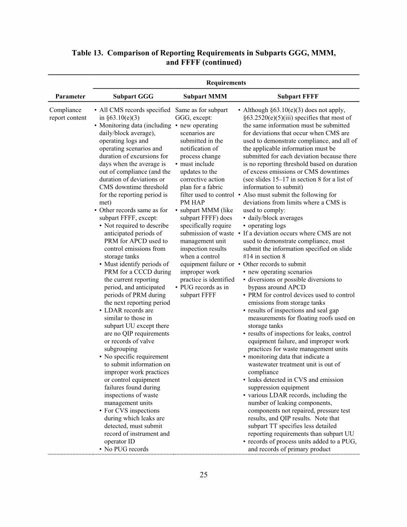
and FFFF (continued)
Requirements
Parameter Subpart GGG Subpart MMM Subpart FFFF
• All CMS records specified •
report content in §63.10(e)(3) GGG, except:
• •
daily/block average), scenarios are for deviations that occur when CMS are
operating logs and
operating scenarios and notification of
duration of excursions for process change
days when the average is • is no reporting threshold based on duration
updates to the
duration of deviations or corrective action (see slides 15–17 in section 8 for a list of
plan for a fabric
for the reporting period is filter used to control •
) PM HAP
• •
subpart FFFF, except: subpart FFFF) does •
• Not required to describe specifically require • operating logs
anticipated periods of • If a deviation occurs where CMS are not
PRM for APCD used to
inspection results
storage tanks when a control #14 in section 8
• •
PRM for a CCCD during •
the current reporting practice is identified •
period, and anticipated • bypass around APCD
periods of PRM during subpart FFFF •
the next reporting period
• •
subpart UU except there storage tanks
•
or records of valve
subgrouping
• •
•
failures found during
inspections of waste •
•
during which leaks are
subpart TT specifies less detailed
operator ID •
•
25
Table 13. Comparison of Reporting Requirements in Subparts GGG, MMM,
Compliance Same as for subpart Although §63.10(e)(3) does not apply,
§63.2520(e)(5)(iii) specifies that most of
Monitoring data (including new operating the same information must be submitted
submitted in the used to demonstrate compliance, and all of
the applicable information must be
submitted for each deviation because there
must include
out of compliance (and the of excess emissions or CMS downtimes
CMS downtime threshold information to submit)
Also must submit the following for
met deviations from limits where a CMS is
Other records same as for subpart MMM (like used to comply:
daily/block averages
submission of waste
management unit used to demonstrate compliance, must
control emissions from submit the information specified on slide
Must identify periods of equipment failure or Other records to submit
improper work new operating scenarios
diversions or possible diversions to
PUG records as in
PRM for control devices used to control
emissions from storage tanks
LDAR records are results of inspections and seal gap
similar to those in measurements for floating roofs used on
are no QIP requirements results of inspections for leaks, control
equipment failure, and improper work
practices for waste management units
No specific requirement monitoring data that indicate a
to submit information on wastewater treatment unit is out of
improper work practices compliance
or control equipment leaks detected in CVS and emission
suppression equipment
various LDAR records, including the
management units number of leaking components,
For CVS inspections components not repaired, pressure test
results, and QIP results. Note that
detected, must submit
record of instrument and reporting requirements than subpart UU
records of process units added to a PUG,
No PUG records and records of primary product

and FFFF (continued)
Requirements
Parameter Subpart GGG Subpart MMM Subpart FFFF
Notification of •
GGG
• does not include language NOCS
clarifying that changes •
within the scope of an least 60 days before planned change
operating scenario are not •
to be reported
• does not require notice for •
Group 1 status •
Table 13. Comparison of Reporting Requirements in Subparts GGG, MMM,
Same as for subpart FFFF, Same as for subpart Describe in compliance reports changes to
process change except: any of the information submitted in the
Provide documentation of the following at
changes to any items in the
precompliance report
change in status of a control device from
changes from Group 2 to small to large
change in status of an emission point
from Group 2 to Group 1
26

Appendix C
# Applicability and Compliance Flowcharts

[This page intentionally left blank.]

1
Flo
wch
art
1.
Ap
pli
cab
ilit
y f
or
sub
pa
rt F
FF
F.
Sta
rt
Are
you
rop
erat
ions
a r
esea
rch
and
deve
lopm
ent
faci
lity?
Do
you
have
fabr
icat
ing
oper
atio
ns s
uch
assp
inni
ng a
pol
ymer
into
its e
nd u
se?
You
r op
erat
ions
are
not s
ubje
ct to
subp
art F
FF
FD
oyo
u ha
ve"a
ffilia
ted
oper
atio
ns"
asso
ciat
ed w
ith a
n af
fect
edso
urce
und
er s
ubpa
rt G
G, K
K,
JJJJ
, MM
MM
, or
SS
SS
?
The
affi
liate
dop
erat
ions
(def
ined
in§6
3.24
35(b
)(3)
)ar
e no
t sub
ject
tosu
bpar
t FF
FF
Are
you
man
ufac
turin
gam
mon
ium
sul
fate
with
capr
olac
tum
?
Is th
eam
mon
ium
sul
fate
prod
uced
as
a by
prod
uct,
and
is th
e H
AP
con
cent
ratio
n<
50 p
pmw
in th
e sl
urry
ente
ring
the
bypr
oduc
tm
anuf
actu
ring
proc
ess?
No
Are
you
man
ufac
turin
g qu
ater
nary
amm
oniu
mco
mpo
unds
?
Yes
Yes
Are
you
man
ufac
turin
g a
chem
ical
in S
IC 2
82, 2
83,
284,
285
, 286
, 287
, 386
,or
NA
ICS
325
?
Yes
Pro
cess
is n
otsu
bjec
t to
subp
art
FF
FF
No
Pro
cess
is s
ubje
ctto
sub
part
FF
FF
Is y
our
proc
ess
a ta
ll oi
lre
cove
ry s
yste
m?
No
Is y
our
proc
ess
prod
ucin
g a
chem
ical
in N
AIC
S 3
2513
1,32
5181
, 325
188,
325
314,
3259
91, o
r32
5992
?
No
Is th
e ch
emic
alhy
draz
ine,
ref
orm
ulat
ed p
last
ic r
esin
sfr
om r
ecyc
led
plas
tics
prod
ucts
, or
phot
ogra
phic
che
mic
als?
Yes
Is y
our
proc
ess
a no
nded
icat
edso
lven
t rec
over
y op
erat
ion
for
a so
lven
t in
one
of th
e su
bjec
tS
IC/N
AIC
Sca
tego
ries?
Is y
our
proc
ess
an a
ffect
ed s
ourc
eor
par
t of a
n af
fect
ed s
ourc
eun
der
anot
her
subp
art
in p
art 6
3?
Yes
Is y
our
proc
ess
subj
ect
to th
e H
ON
?Y
esA
ll ba
tch
proc
ess
vent
s ar
e su
bjec
tto
sub
part
FF
FF
No
Pro
cess
is n
otsu
bjec
t to
subp
art
FF
FF
No
Yes
Pro
cess
is s
ubje
ctto
sub
part
FF
FF
No
No
No
No
Yes
No
No
Yes N
o
Yes
YesYes
Yes

2
Flo
wch
art
2.
Ap
pli
cab
ilit
y d
eter
min
ati
on
for
wast
ewa
ter
stre
am
s.
Sta
rt
Is P
SH
AP
conc
entr
atio
n<5
0 pp
mw
?N
o
Yes
Is th
ew
aste
wat
er s
trea
mpa
rt o
f an
exis
ting
sour
ce?
No
Is S
HA
Pco
ncen
trat
ion
> 4,
500
ppm
w?
No
Was
tew
ater
stre
am is
not
subj
ect t
o co
ntro
l
Yes
Is S
HA
Pco
ncen
trat
ion
> 30
,000
ppm
w?
Yes
Is to
tal
annu
al lo
ad o
f SH
AP
inth
e w
aste
wat
er s
trea
m>
1 tp
y?
Yes
Yes
Was
tew
ater
stre
am is
not
subj
ect t
o co
ntro
l
Was
tew
ater
stre
am is
not
subj
ect t
o co
ntro
l
Is to
tal
PS
HA
P a
ndS
HA
P c
once
ntra
tion
> 10
,000
ppm
w?
No
Is to
tal
PS
HA
P a
ndS
HA
P c
once
ntra
tion
> 1,
000
ppm
w?
No
Yes Is
annu
al a
vera
geflo
wra
te o
f was
te-
wat
er s
trea
m>
1 l/m
in
Was
tew
ater
stre
am is
not
subj
ect t
o co
ntro
l
No
Was
tew
ater
stre
am is
not
subj
ect t
o co
ntro
l
Yes
Was
tew
ater
str
eam
is a
Gro
up 1
str
eam
and
is s
ubje
ct to
the
emis
sion
sup
pres
sion
and
trea
tmen
t req
uire
men
ts in
sub
part
FF
FF
.
Yes
No N
o
Not
e: PS
HA
P m
eans
par
tially
sol
uble
HA
P li
sted
inT
able
8 to
sub
part
FF
FF
.
SH
AP
mea
ns s
olub
le H
AP
list
ed in
Tab
le 9
tosu
bpar
t FF
FF
.

3
Flo
wch
art
3. E
mis
sion
su
pp
ress
ion
req
uir
em
ents
for
wast
e m
an
agem
ent
un
its.
Mus
t mee
t one
of t
hese
cont
rol r
equi
rem
ents
:a
An
air-
supp
orte
d or
rigid
cov
er w
ith a
clos
ed-v
ent s
yste
mth
at r
oute
s or
gani
cH
AP
vap
ors
to a
cont
rol d
evic
eb
OR
Flo
atin
g fle
xibl
em
embr
ane
cove
r
Was
te M
anag
emen
tU
nits
for
Gro
up 1
Was
tew
ater
Co
nta
iner
s(§
63.1
35)
Ind
ivid
ual
Dra
inS
yste
ms
(§§6
3.13
6 an
d63
.248
5(e)
)
Oil-
Wat
erS
epar
ato
rs(§
63.1
37)
Su
rfac
eIm
po
un
dm
ents
(§63
.134
)
Was
tew
ater
Tan
ks(§
§63.
133
and
63.2
485(
d))
AN
DA
ND
AN
DA
ND
See
Flo
wch
art 4
Mus
t mee
t the
seco
ntro
l req
uire
men
ts:a
A c
over
on
each
cont
aine
r us
ed to
hand
le, t
rans
fer,
or
stor
e G
roup
1w
aste
wat
erA
ND
For
con
tain
ers
with
aca
paci
ty >
0.4
2 m
3 , a
subm
erge
d fil
l pip
em
ust b
e us
edA
ND
If tr
eatm
ent i
spe
rfor
med
in th
eco
ntai
ner,
then
loca
teit
in a
n en
clos
ure
with
a c
lose
d-ve
ntsy
stem
that
rou
tes
HA
P v
apor
s to
aco
ntro
l dev
iceb
Mus
t mee
t eith
er o
fth
ese
cont
rol
requ
irem
ents
:a
Eac
h op
enin
g of
the
drai
n sy
stem
mus
t be
cove
red,
and
ifve
nted
, rou
te H
AP
vapo
rs to
a c
ontr
olde
vice
b
OR
Eac
h dr
ain
mus
t be
equi
pped
with
wat
erse
al c
ontr
ols
and/
ortig
htly
fitti
ng c
aps
and
plug
s; e
ach
junc
tion
box
mus
t be
equi
pped
with
aco
ver,
and
if v
ente
d,c
vapo
rs m
ust b
ero
uted
to a
con
trol
devi
ceb ;
and
sew
erlin
es m
ust n
ot b
eop
en to
the
atm
osph
ered
Mus
t mee
t eith
er o
fth
ese
cont
rol
requ
irem
ents
:a
A fi
xed
roof
and
acl
osed
-ven
t sys
tem
that
rou
tes
orga
nic
HA
P v
apor
s to
aco
ntro
l dev
iceb
OR
A fl
oatin
g ro
of th
atm
eets
the
requ
irem
ents
of
subp
art Q
of 4
0C
FR
60
aP
art o
f the
req
uire
men
ts fo
r ea
ch W
MU
incl
udes
per
iodi
c in
spec
tions
for
impr
oper
wor
k pr
actic
es a
nd c
ontr
ol e
quip
men
t fai
lure
s an
d an
y ne
cess
ary
repa
irs.
bT
he c
ontr
ol d
evic
e m
ust r
educ
e to
tal o
rgan
ic H
AP
by
> 95
% o
r to
an
outle
t TO
C o
ror
gani
c H
AP
con
cent
ratio
n <
20 p
pmv.
Not
e th
at th
e 20
ppm
v op
tion
is n
ot a
llow
edfo
r no
ncom
bust
ion
devi
ces
used
to c
ontr
ol e
mis
sion
s fr
om s
urfa
ce im
poun
dmen
tsan
d co
ntai
ners
. A
ltern
ativ
ely,
the
cont
rol d
evic
e m
ay b
e a
com
bust
ion
devi
ce w
ith a
resi
denc
e tim
e >
0.5
seco
nds
and
a te
mpe
ratu
re >
760
o C, o
r a
flare
that
mee
ts th
eco
nditi
ons
in §
63.1
1(b)
, or
a R
CR
A-p
erm
itted
uni
t.c
Ven
ting
to th
e at
mos
pher
e is
allo
wed
und
er c
erta
in c
ondi
tions
as
spec
ified
in§6
3.13
6(e)
(2)(
ii).
dV
entin
g to
the
atm
osph
ere
is a
llow
ed u
nder
cer
tain
con
ditio
ns a
s sp
ecifi
ed in
§63.
2485
(e).

4
Flo
wch
art
4.
Em
issi
on
su
pp
ress
ion
req
uir
emen
ts f
or
wast
ewa
ter
tan
ks.
Sta
rt
Are
the
cont
ents
of t
he w
aste
wat
erta
nks
heat
ed, t
reat
ed b
y m
eans
of
exot
herm
ic r
eact
ion,
or s
parg
ed?
Yes
No
Yes
Is th
eM
TV
Pb
of th
e P
SH
AP
and
SH
AP
in th
ew
aste
wat
er>
13.1
kP
a?
No
Is th
eM
TV
Pb
of th
eP
SH
AP
and
SH
AP
inth
e w
aste
wat
er >
5.2
kP
a?
Con
trol
em
issi
ons
usin
g a
fixed
roo
f
Is th
eca
paci
ty o
f the
was
tew
ater
tank
>15
1 m
3 ?
Yes
No
Is th
eca
paci
ty o
f the
was
tew
ater
tank
> 75
m3 ?
Yes
No
No
Con
trol
em
issi
ons
usin
g a
fixed
roo
f
Mus
t mee
t the
se c
ontr
ol r
equi
rem
ents
:
Equ
ipm
ent o
ptio
nsA
fixe
d ro
of w
ith a
clo
sed
vent
sys
tem
that
rou
tes
orga
nic
HA
P v
apor
s to
aco
ntro
l dev
ice,
a or
A fi
xed
roof
with
an
inte
rnal
floa
ting
roof
that
mee
ts th
e re
quire
men
ts o
f§6
3.11
9(b)
or
subp
art W
W, o
rA
n ex
tern
al fl
oatin
g ro
of th
at m
eets
the
requ
irem
ents
of §
63.1
19(c
) or
sub
part
WW
Use
a fi
xed
roof
and
dem
onst
rate
that
the
PS
HA
P a
nd S
HA
P e
mis
sion
s fr
om th
eta
nk a
re n
o m
ore
than
5%
hig
her
than
ifth
e co
nten
ts o
f the
tank
wer
e no
t hea
ted,
trea
ted
by e
xoth
erm
ic r
eact
ion,
or
spar
ged
Per
iodi
c in
spec
tions
and
rep
airs
for
impr
oper
wor
k pr
actic
es a
nd c
ontr
ol e
quip
men
t fai
lure
s
Yes
aT
he c
ontr
ol d
evic
e m
ust r
educ
e to
tal o
rgan
ic H
AP
by
> 95
% o
r to
an
outle
t TO
C o
r or
gani
c H
AP
conc
entr
atio
n <
20 p
pmv.
Alte
rnat
ivel
y, th
e co
ntro
lde
vice
may
be
a c
ombu
stio
n de
vice
with
a r
esid
ence
time
> 0.
5 se
cond
s an
d a
tem
pera
ture
> 7
60o C
, or
afla
re th
at m
eets
the
cond
ition
s in
§63
.11(
b), o
r a
RC
RA
-per
mitt
ed u
nit.
bM
TV
P m
eans
max
imum
true
vap
or p
ress
ure.

5
Flo
wch
art
5.
In
itia
l co
mp
lia
nce
fo
r p
roces
s v
ents
.
No
requ
irem
ents
for
Gro
up 2
Ven
ts
Cal
cula
te u
ncon
trol
led
HA
P e
mis
sion
s or
desi
gnat
e G
roup
1
Com
ply
with
63.
115(
d);
calc
ulat
e T
RE
or
desi
gnat
e as
Gro
up 1
;m
easu
rem
ents
req
uire
dfo
r 5.
0>T
RE
>1.9
Bat
ch
Con
tinuo
usId
entif
y pr
oces
sve
nts
per
defin
ition
Gro
up 1
Gro
up 1
No
Yes
Cal
cula
te c
ontr
olle
dem
issi
ons
usin
geq
uatio
ns in
§63
.125
7of
sub
part
GG
G
Is th
eco
ntro
l dev
ice
orre
cove
ry d
evic
e a
cond
ense
r?N
o
Sm
all
cont
rol d
evic
e(e
xclu
ding
flare
s)?
Con
duct
des
ign
eval
uatio
n in
acco
rdan
ce w
ith§6
3.12
57(a
) of
subp
art G
GG
Cal
cula
te u
ncon
trol
led
hydr
ogen
hal
ide
and
halo
gen
HA
P e
mis
sion
s
Yes
All
vent
s
No
requ
irem
ents
for
<1,0
00 lb
/yr/
proc
ess
Or
Or
>1,0
00 lb
/yr/
proc
ess
Con
duct
ape
rfor
man
ce te
stas
spe
cifie
d in
§63.
997
and
§63.
1257

6
Flo
wch
art
6. M
on
ito
rin
g f
or
ven
t st
rea
ms.
Com
ply
with
Sub
part
SS
§63.
987(
c): F
lare
s§6
3.98
8(c)
: Inc
iner
ator
s, B
oile
rs a
nd P
roce
ss H
eate
rs§6
3.99
0(c)
: Abs
orbe
rs, C
onde
nser
s, a
nd C
arbo
n A
dsor
bers
use
d as
Con
trol
Dev
ices
§63.
994(
c): H
alog
en s
crub
bers
and
Hal
ogen
Con
trol
Dev
ices
§63.
996:
Gen
eral
Mon
itorin
g R
equi
rem
ents
§63.
998(
b) a
nd (
c) a
nd §
63.9
99(c
)(6)
: Dat
a A
vera
ging
, Dat
a A
vaila
bilit
y R
equi
rem
ents
, QA
/QC
, and
Rec
ords
§63.
999(
b)(3
): P
roce
dure
s fo
r E
stab
lishi
ng th
e O
pera
ting
Lim
its
Sub
part
SS
63.
993
(Abs
orbe
rs, c
onde
nser
s, c
arbo
nad
sorb
ers
and
othe
r re
cove
ryde
vice
s us
ed a
s fin
al r
ecov
ery
devi
ces)
No
mon
itorin
g
Is th
eem
issi
onst
ream
cont
rolle
d?
Is th
eem
issi
onst
ream
from
aw
aste
wat
erm
anag
emen
tun
it?
Yes
No
Sub
part
G
Yes
No
Is th
eem
issi
on s
trea
ma
cont
inuo
us p
roce
ssve
nt w
ith a
rec
over
yde
vice
?
No
Is th
eem
issi
on s
trea
m a
batc
h pr
oces
sve
nt?
Com
plyi
ngw
ithal
tern
ativ
est
anda
rd?
Is th
eto
tal u
ncon
trol
led
HA
P in
to th
eco
ntro
l dev
ice
<1 T
PY
?C
onfir
m th
at th
e de
vice
is o
pera
ting
prop
erly
(per
iodi
c ve
rific
atio
n) b
yco
nduc
ting
appr
oved
daily
or
per
batc
hde
mon
stra
tions
Yes
No
Yes
No
Usi
ngco
mbu
stio
n co
ntro
lde
vice
with
aci
d ga
ssc
rubb
er?
Yes
No
No
Yes
Hal
ogen
ated
ven
tst
ream
? Yes
Use
CE
MS
to m
onito
rT
OC
and
/or
HC
l/Cl 2/
HF
No
Use
CE
MS
tom
onito
r T
OC
Use
CE
MS
tom
onito
r H
Cl/C
l 2/H
Fin
scr
ubbe
r ou
tlet
Or
Sta
rt
Yes

Appendix D
# Case Study Data

[This page intentionally left blank.]

1
Cas
e S
tud
y N
o. 1
Silo
Dis
char
ge
Ves
sel
Ves
sel
A
Ato
Hex
ane
ST
Pel
let
Dry
er
Un
reac
ted
mo
no
mer
to
u
pst
ream
ole
fin
s u
nit
s
Off
gas
Nit
rog
en
To
Bag
ho
use
Po
wd
er
Cat
alys
t
Eth
ylen
e
Hyd
rog
en
Pro
pyl
ene
Pu
rge
Co
nti
nu
ou
s R
eact
or
An
alyz
ers
To
Bag
ho
use
Nit
rog
en/
Ste
am
Pel
lets
to
Silo
Ext
rud
er a
nd
Die
Fac
e C
utt
er

Ventas a Batch
or
Vent MON? Comment Continuous
Vent? (scfm) (ppmv)
BuildingNo NA
Purge Vessel Batch 150 300 8,400 4,980
No Less than 50 ppmv HAP
NA 150 20
Less than 50 ppmv HAP
NA 150 ND
Conclusion: None of the vents are Group 1, so none require control.
1
Number Material GallonsMTVP
)
1 Fixed roof 15,000 57 20 1
Process Vent Characteristics for Case Study No. 1
Regulated Process
Regulated Vent Stream Characteristics
HAP HAP Under the Flowrate Concentration Hours of
Operation Emissions,
lb/yr
Analyzer They have no HAP
Yes
Powder Silo
Pellet Dryer No
Storage Tank Characteristics for Case Study No.
Storage Tank Type
Capacity (kPa Group
Hexane
This tank would require control under the MON.
2

3
Cas
e S
tud
y N
o. 2
C-1 R-1
F-1
R-2
C-2
R-5
R-3
SS
-1
Fee
d T
ank
ST
-2
MeO
H
T-1
Met
han
ol
Sto
rag
e T
ank
RX
-1
PO
D
Ext
ract
ion
(E
XT
-1)
ST
-1
Pu
rge
To
luen
e S
tora
ge
Tan
k H
old
ing
Tan
kT
-2
C-3
T
-3
Ho
ldin
g
Co
nd
ense
r C
-4
Tan
k
pro
cess
R
-4
PO
D
D-1
S
team
S
trip
per
p
rod
uct
PO
D
PO
D
Co
nti
nu
ou
s D
isti
llati
on

Assumptions for Case Study No. 2
This case study does not represent any single process but instead was developed to illustrate how the standard could be implemented on a model process. Presented below are assumptions used to develop emission calculations.
1. The reactor and upstream batch unit operations are operated for 2,000 batches/yr.
2. The steam stripper operates at 120°C.
3. To simplify the illustration, the emission calculations ignore the volumes of non-volatile reactants and products.
4. We assumed the contents of receivers were equal to the contents of reactor and disitllation column at the initiation of vacuum activities.
5. For heatup activities, the still pot volume was assumed to be 1,000 gallons, while the reactor volume was assumed to be 6,000 gallons.
6. The aqueous phase from the extraction contains 20% of the toluene and 80% of the methanol; the organic phase contains the remainder.
7. The column bottoms from the continuous distillation operation contain 90% by weight of the incoming (feed) water and methanol and only 1% by weight of the incoming toluene.
4

Example TRE Calculations
MW Conc Hj Hj
Compound HAP (lbs/hr) (kg/hr) (g/gmol) (gmol/hr) ppmv (kcal/gmol) (kcal/hr)
Toluene Yes 0.32 0.15 92 1.602101 3,352 901.5 1444.29448
Methanol Yes 0.19 0.08 32.04 2.624851 5,492 161 422.601053
Water No 0.16 0.07 18 4.037144 8,447 0 0
Air No 30.00 13.62 29 469.6552 982,708 0 0
Total 30.67 13.92 477.9193 1,000,000 1866.89553
Etoc (minus ethane) kg/hr 0.23 Ehap kg/hr 0.23 Flow DSCMM 0.19 Ht, Mj/SCM 0.69
TRE Calculation a b c d TRE Control Device Non-halogenated flare 1.935 0.366 -0.00769 -0.00073 8.63 non-halogenated incinerator 0% 1.492 0.0627 0.0318 -0.00116 6.59 recovery non-halogenated incinerator 70% 2.519 0.0118 0.013 0.0479 10.98 recovery
None of the above TRE are less than 1.9, therefore, this stream is not a Group 1 continuous stream.
TRE1
a b Q c HT d ETOCE S
HAP
Where:
EHAP = Emission rate of total organic HAP, kg/hr Q = Vent stream flow rate, scmm S
EHT = Vent stream net heating valve, MJ/scm
TOC = Emission rate of TOC (minus methane and ethane), kg/hr.
5

IDControl
Displacement Single Phase: Raoults LawCharge Methanol 0.36 0.36
RX-1 Reactor Displacement Single Phase: Raoults LawCharge Methanol 0.04 0.04
RX-1 Reactor 0.03 Heat Up Single Phase: Raoults LawHeatup Methanol 0.07 0.03
0.00 0.00RX-1 Reactor Water
operationSingle Phase: Raoults LawVacuum Methanol 1.42 1.42
Distillation 0.00 0.00Displacement Single Phase:
Raoults LawMethanol 0.31 0.31
Charge DisplacementLawMethanol 0.11 0.11
0.70 0.70
LawMethanol 2.62 2.6217.46 17.46
Charge Displacement Single Phase: Raoults LawAqueous
Phase to Methanol 0.26 0.26
0.03 0.03
SS-1 Displacement Single Phase: Raoults LawStripper Methanol 0.26 0.26
0.03 0.03SS-1 Strip Single Phase:
Raoults Lawaqueous Methanol 0.04 0.04mix 0.00 0.00
R-3Receiver
DisplacementLawMethanol 0.35 0.35
Charge 0.07 0.07
Methanol 5.84 5.7718.30 18.30
24.14 24.06lb/batch
Control 0.30%
2000
48270.65 48124.74
Summary of Batch Process Vent Emissions
Equipment Emission Event Materials
Uncontrolled Emissions
Devices
Controlled Emissions
Calculation Assumptions lbs/batch lbs/batch T-1 Feed Tank Water
Toluene Water 0.03 0.03
Toluene Water 0.09 C-1
Toluene 1.21 1.21 Vacuum
Toluene EXT-1 Charge to Water 0.33 0.33
Extraction
Toluene EXT-1 Water 0.11 0.11 2-phase Raoult's
Toluene to Extraction Toluene
EXT-1 Purge Water 2.40 2.40 Purge 2-phase Raoult's Extraction
Toluene T-2 Water 0.28 0.28
Hold Tank Toluene
Charge Water 0.28 0.28
Toluene Water 0.04 0.04 Heatup/Distill
Toluene Stripper Water 0.05 0.05 2-phase Raoult's
Toluene
Toluene
Total,
Efficiency
Batches/yr
lb/yr
Therefore, 98% control required for Batch Vents
6
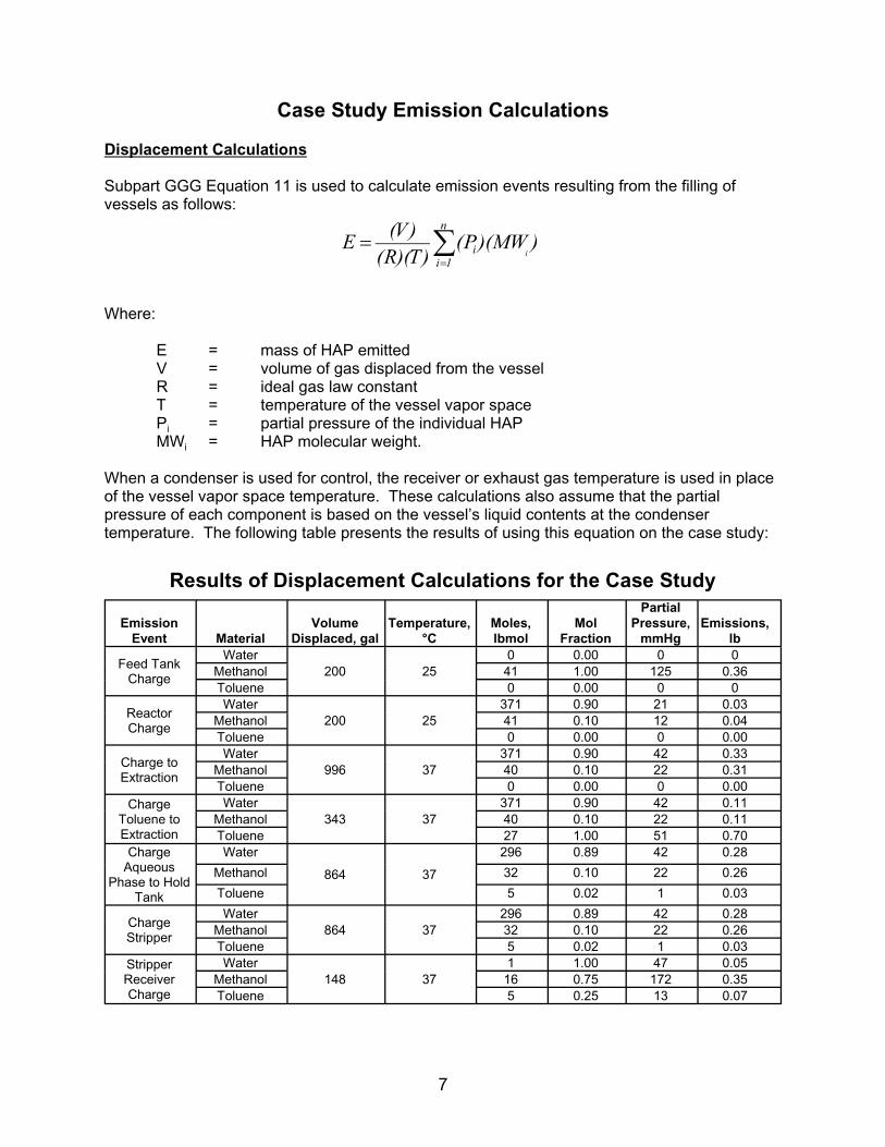
Case Study Emission Calculations
Displacement Calculations
Subpart GGG Equation 11 is used to calculate emission events resulting from the filling of vessels as follows:
Where:
E = mass of HAP emitted V = volume of gas displaced from the vessel R = ideal gas law constant T = temperature of the vessel vapor space Pi = partial pressure of the individual HAP MWi =
When a condenser is used for control, the receiver or exhaust gas temperature is used in place
pressure of each component is based on the vessel’s liquid contents at the condenser
Results of Displacement Calculations for the Case Study Partial
Volume Mol°C lbmol mmHg lb
Charge 200 250 0 0
Methanol 41 1.00 125 0.36 0 0 0
ReactorCharge 200 25
371 0.90 21 0.03 Methanol 41 0.10 12 0.04
0 0 0.00
Charge to 996 37371 0.90 42 0.33
Methanol 40 0.10 22 0.31 0 0 0.00
Charge343 37
371 0.90 42 0.11 Methanol 40 0.10 22 0.11
27 1.00 51 0.70 Charge
AqueousPhase to Hold 864 37
296 0.89 42 0.28
Methanol 32 0.10 22 0.26
5 1 0.03
ChargeStripper 864 37
296 0.89 42 0.28 Methanol 32 0.10 22 0.26
5 1 0.03 StripperReceiver 148 37
1Methanol 16 0.75 172 0.35
Charge 5
HAP molecular weight.
of the vessel vapor space temperature. These calculations also assume that the partial
temperature. The following table presents the results of using this equation on the case study:
Emission Temperature, Moles, Pressure, Emissions, Event Material Displaced, gal Fraction
Feed Tank Water 0.00
Toluene 0.00 Water
Toluene 0.00
Extraction
Water
Toluene 0.00
Toluene to Water
Extraction Toluene
Tank
Water
Toluene 0.02
Water
Toluene 0.02 Water 1.00 47 0.05
Toluene 0.25 13 0.07
7

Case Study Emission Calculations
Purging
Emissions from purging operations are calculated using Equation 12 of Subpart GGG as follows:
n
E PMWi
(V )(t) PTi m
i 1 )(( T R )(P (Pj ))T
j 1
Where:
E = mass of HAP emitted V = purge flow rate at temperature and pressure of the vessel vapor space R = ideal gas law constant T = temperature of the vessel vapor space, absolute Pi = partial pressure of the individual HAP Pj = partial pressure of individual condensable VOC compounds PT = pressure of the vessel vapor space MWi = molecular weight of the HAP t = time of purge n = number of HAP components m = number of condensable compoents.
Results of Purging Calculations for the Case Study
PartialFlowrate, Temperature, Duration, Moles, Mol Pressure, Emissions,
Event Material scfm °C hr lbmol Fraction mmHg lbWater 371 0.85 20 2.40
Purge Methanol 5 25 6 40 0.10 12 2.62Extraction Toluene 27 1.00 28 17.46
8
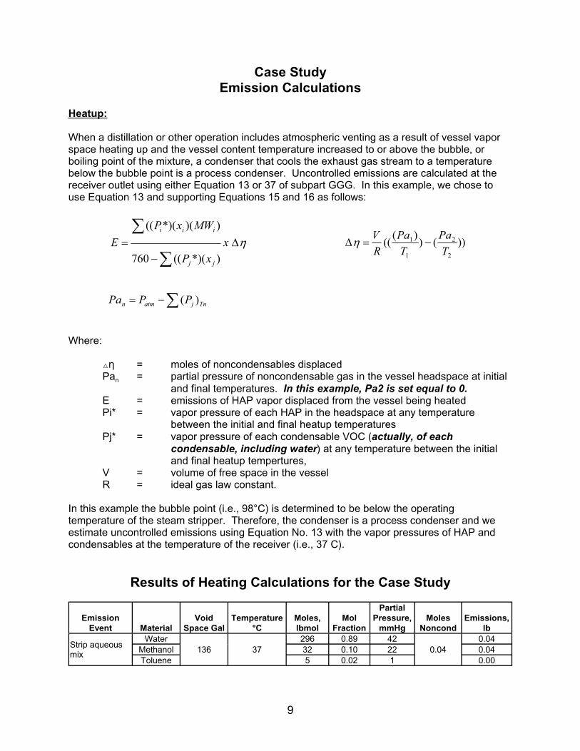
Case Study Emission Calculations
Heatup:
When a distillation or other operation includes atmospheric venting as a result of vessel vapor space heating up and the vessel content temperature increased to or above the bubble, or boiling point of the mixture, a condenser that cools the exhaust gas stream to a temperature below the bubble point is a process condenser. Uncontrolled emissions are calculated at the receiver outlet using either Equation 13 or 37 of subpart GGG. In this example, we chose to use Equation 13 and supporting Equations 15 and 16 as follows:
)( *)( (( MW )Pi xi i V
E x (((Pa1)
) (Pa2 ))
760 ((Pj *)(x j ) R T1 T2
Pan Patm (Pj )Tn
Where:
= moles of noncondensables displaced Pan = partial pressure of noncondensable gas in the vessel headspace at initial
and final temperatures. In this example, Pa2 is set equal to 0. E = emissions of HAP vapor displaced from the vessel being heated Pi* = vapor pressure of each HAP in the headspace at any temperature
between the initial and final heatup temperatures Pj* = vapor pressure of each condensable VOC (actually, of each
condensable, including water) at any temperature between the initial and final heatup tempertures,
V = volume of free space in the vessel R = ideal gas law constant.
In this example the bubble point (i.e., 98°C) is determined to be below the operating temperature of the steam stripper. Therefore, the condenser is a process condenser and we estimate uncontrolled emissions using Equation No. 13 with the vapor pressures of HAP and condensables at the temperature of the receiver (i.e., 37 C).
Results of Heating Calculations for the Case Study
PartialEmission Void Temperature Moles, Mol Pressure, Moles Emissions,
Event Material Space Gal °C lbmol Fraction mmHg Noncond lbWater 296 0.89 42 0.04
Strip aqueous Methanol 136 37 32 0.10 22 0.04 0.04mixToluene 5 0.02 1 0.00
9

Case Study Emission Calculations
Vacuum Operation
Emissions from vacuum operations are calculated using Equation No. 33 of Subpart GGG as follows:
n
MW P ii
(La)(t) i 1E MW NC
m
Psystem Pj
j 1
Where:
E = mass of HAP emitted from the vacuum operation La = total air leak rate in the system, mass/time t = time of vacuum operation MWi = molecular weight of individual HAP with partial pressures calculated at the
P
PMW
temperature of the receiver nc = molecular weight of noncondensables
i = partial pressure of HAP at receiver temperature Pj = partial pressure of condensable at receiver temperature
system = absolute pressure of receiving vessel.
Results of Vacuum Calculations for the Case Study
Leak PartialEmission Rate, Temp of Duration, Moles, Mol Pressure, Emissions*,
Event Material lb/hr Receiver, °C hr lbmol Fraction mmHg lb or lb/hr
370.66 0.90 8 1.21 Reactor Water
Vacuum Methanol 30 10 6 41.17 0.10 5 1.42 Distillation Toluene 0.00 0.00 0
Water 74.23 0.71 6 0.16 Continuous Methanol 30 10 NA 8.14 0.08 4 0.19 Dist
Toluene 21.66 0.21 3 0.32 * If no duration is specified, as in continuous distillation, emissions are in a lb/hr basis
10

Case Study Emission Calculations
Heatup:
When a distillation or other operation includes atmospheric venting as a result of vessel vapor space heating up to a temperature lower than the bubble, or boiling point of the mixture, uncontrolled emissions are calculated using Equations 18, 19, and 20 of subpart GGG.
n
PT Pi 1,
i 1E MWHAP x N AVG x lnn
ni 2 , ni 1,
PT Pi 2 ,
i 1
VPT 1 1N AVG
2R T1 T2
n nVni 2 , ni 1,
( T R ) i 1
Pi 2 ,
VPi 1,
)( 2 T R 1 i 1
Where:
MWHAP = average molecular weight of HAP PT = total pressure in the vessel T1, T2 = initial and final temperatures of vessel Pi, = partial pressure of individual HAP at T1 and T2 1 and 2
N
E = emissions of HAP vapor displaced from the vessel being heated V = volume of free space in the vessel R = ideal gas law constant
AVG = average gas space molecular volume ni,1 and ni,2 = moles of condensable in vessel headspace at T1 and T2.
Results of Heating Calculations for the Case Study
Void Emission Space
Event Material Gal T1, °C T2, °C T3, °C NAVG
Partial PartialPressure Pressure
Moles, Mol at T1, at T2, Emissions,lbmol Fraction mmHg mmHg (ni,2-ni,1) MW lb/event
Water 371 0.90 21 42 0.04 18 0.09 Reactor Heatup Methanol 5,000 25 37 10 1.67 41 0.10 12 23 0.02 32 0.07
Toluene 0 0.00 0 0
11

Case Study Emission Calculations (continued)
Further, the rule specifies the use of Equations 13 and 15 (presented in the heatup worksheet) or 15 and 37 to calculate emissions from the condenser receiver outlet temperature of 10°C.
Equation 37 is presented below.
n
Pi
Ei 1
m MWHAP
PT Pjj 1
Where:
Pj = partial pressure of condensables at receiver temperature = moles of noncondensable gas displaced.
EmissionsMoles After
Emission Pa1, Pa2, Pa3, Noncond, Partial Pressure 10°CEvent Material mmHg mmHg mmHg Delta N at T3, mmHg Condenser
Water 8 0.03ReactorHeatup Methanol 726 695 746 0.1308 5 0.03
Toluene 0 0.00
Note: In these equations, three temperatures are evaluated as follows: T1 = Initial temperature of the reactor T2 = Temperature to which the reactor is heated T3 = Temperature that is achieved by the condenser.
12

Case Study Emission Calculations
Bubble Point Calculation:
The bubble point of a material or mixture of materials is the temperature at which the total partial
bubble point is important in Subpart GGG because it determines whether a condenser is a
from a temperature above the boiling point to a temperature that is below the boiling point, the
cooling occurs, then the condenser is functioning as an air pollution control device.
Calculation:
A simple way to calculate the bubble point is to select a temperature, calculate the partial pressures of the condensable materials at that temperature, and then verify that the total partial
below, a bubble point calculation was conducted.
PartialMol
°C lbmol mmHg
296 0.89 621
864.40 760Strip aqueous mix Methanol 98 32 0.10 235
5 8
pressure of the condensable materials in the system equals the pressure of the system. The
process condenser or a control device for atmospheric vents. If the condenser cools a material
condenser functions as a process condenser. If the material is below the bubble point, and
pressure of the condensables equals or is greater than the systems pressure. For the event
Total Partial Temperature, Moles, Pressure, Pressure of System
Emission Event Material Fraction Condensables Pressure
Water
Toluene 0.02
13

14 14
Mat
eria
l Bal
ance
fo
r E
xam
ple
Pro
cess
Eq
uip
men
t ID
E
mis
sio
n E
ven
t M
ater
ials
M
ass
In
Lo
ss
Mas
s O
ut
Du
rati
on
, hr
Flo
wra
te,
scfm
Cyc
le
Tim
e, h
rlb
gal
lb lb
F
eed
Tan
k C
harg
e W
ater
0.25
1.
75
0.25
T-1
Met
hano
l13
18
200
0.36
13
18
Tol
uene
Rea
ctor
Cha
rge
Wat
er
6672
80
0 0.
03
6672
0.
25
1.75
0.
5R
X-1
Met
hano
l13
18
200
0.04
13
18
Tol
uene
Rea
ctor
Hea
tup
Wat
er
6672
80
0 0.
03
6672
6
0.02
6.
5R
X-1
Met
hano
l13
18
200
0.03
13
18
Tol
uene
Rea
ctor
Vac
uum
W
ater
6672
80
0 1.
21
6671
6
6.64
12
.5R
X-1
Dis
tilla
tion
Met
hano
l13
18
200
25.4
1 12
92
Tol
uene
0 0
0.00
0
Cha
rge
to E
xtra
ctio
n W
ater
66
71
800
0.33
66
70
1 2.
10
13.5
EX
T-1
Met
hano
l12
92
196
0.31
12
92
Tol
uene
0C
harg
e T
olue
ne to
W
ater
6670
80
0 0.
11
6670
0.
25
2.89
13
.75
EX
T-1
Ext
ract
ion
Met
hano
l12
92
196
0.11
12
92
Tol
uene
2486
34
3 0.
70
2485
P
urge
Ext
ract
ion
Wat
er
6670
80
0 2.
40
6668
6
5.43
19
.75
EX
T-1
Met
hano
l12
92
196
2.62
12
89
Tol
uene
2485
34
3 17
.46
2468
C
harg
e A
queo
us
Wat
er53
34
640
0.28
53
34
1 1.
82
20.7
5T
-2P
hase
to H
old
Tan
k M
etha
nol
1031
15
7 0.
26
1031
T
olue
ne49
4 68
0.
03
494
Cha
rge
Str
ippe
r W
ater
53
34
640
0.28
53
34
1 1.
82
21.7
5S
S-1
Met
hano
l10
31
156
0.26
10
31
Tol
uene
494
68
0.03
49
4 S
trip
aqu
eous
mix
W
ater
53
34
640
0.04
53
34
0.25
1.
15
22S
S-1
Met
hano
l10
31
156
0.04
10
31
Tol
uene
494
68
0.00
49
4 S
trip
per
Rec
eive
r W
ater
20
2 0.
05
20
0.5
0.62
22
.5R
-3C
harg
eM
etha
nol
515
78
0.35
51
5 T
olue
ne48
9 67
0.
07
489

Compound lb/lbmola b c
18.35 3844.9 228.16 130 47 24 17 9 1 8.34
Methanol 7.897 1474.08 229.13 556 228 125 96 54 32 0.79 6.59
6.954 1344.8 219.48 123 51 28 22 12 92 0.87 7.26
Air 29
Example Storage Tank Applicability
Material Stored Methanol25,000 25,000 10,000
135213 245
Operating Pressure, psig 30 atm
Subpart FFFF Applicability Yes Yes95 95 38
28 33
YesNo Yes
No
POD Stream SS
Bottoms R-2 R-5
DistillationBottoms
D-1
Gallons/Yr 9,600,000 9,600,000 365,041
Concentration, ppmw 858 NA 100 13,676
Basis Material balance
Annual Average Methanol Concentration, ppmw 88,341 600 600 160,957
Yes No No
Physical Data
Vapor Pressure Vapor Pressures, mmHg Molecular
Weight Density
Antoine's Coefficients
Equation
Temperature, °C
sg lb/gal 57 37 25 20 10
Water P=exp(a-b/(T+c)) 18
P=10^(a-b/(T+c))
Toluene P=10^(a-b/(T+c))
Tank ID ST-1 ST-2 T-3 Toluene Organic phase prior to continuous distillation
Capacity, gallons Maximum Bulk Storage Temp, F 96 96 Maximum True Vapor Pressure, mmHg 48
atm
Tank is a pressure tank; however working losses are possible
Capacity, m3 Maximum True Vapor Pressure, kPa 6.4
>38 m3 capacity Yes Yes > 6.9 kPa Yes
Control required? Yes Yes
Example Wastewater Stream Analysis
Ejector Condenser
Ejector Condenser
1,432,088
Annual Average Toluene
Material balance Analysis Analysis
Affected Group 1 Wastewater ? Yes
15

[This page intentionally left blank.]

Appendix E
# Summary of Equations Used to Calculate Uncontrolled Process Vent Emissions
# Exercises

[This page intentionally left blank.]

Table
E-1
. Sum
mary
of
Equations
Use
d t
o C
alc
ula
te
Unco
ntr
olle
d P
roce
ss V
ent
Em
issi
ons
Eq
ua
tio
n
nu
mb
er
in
Em
issio
n e
ve
nt
su
bp
art
GG
G
No
tes
Vapor
dis
pla
cem
ent
EV
RT
i i
i1
nEq. 11
Purg
ing
EV
t
RT
P
P
P
i i
i1
nT
Tj
j1
m
Eq. 12
Heating
N
P
P
P
P
n
nH
AP
A
VG
Ti
1
n
Ti
1
n
Eq. 18
i,2
ni,1)
usi
ng
Equation 2
0 in s
ubpart
GG
G.
avg u
sing
Equation 1
9 in s
ubpart
GG
G.
Depre
ssuriza
tion
EV
RT
ln
P
P
P
P
1i
i1
n
2i
i1
ni
i i
1
n
Eq. 32
vess
el bein
g d
epre
ssurize
d.
1
Eq
ua
tio
n
PM
W
1.
V e
quals
dis
pla
ced v
olu
me.
P
MW
1.
Ass
um
e 2
5%
of
satu
ration if
flow
is
> 1
00 s
cfm
.
2.
V e
quals
purg
e f
low
rate
.
EM
W
ln
i,1
i,2
i,2
i,1
1.
Analy
tica
l so
lution.
2.
Calc
ula
te (
n
3.
Calc
ula
te N
PM
W
1.
Analy
tica
l so
lution.
2.
V e
quals
fre
e v
olu
me in t
he
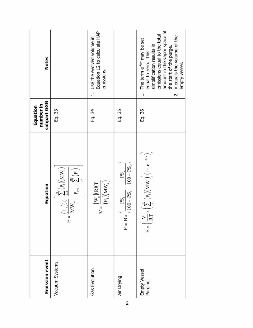
2
Em
issio
n e
ve
nt
Eq
ua
tio
n
nu
mb
er
in
su
bp
art
GG
G
No
tes
Vacu
um
Syst
em
s
EL
t
MW
P
P
a
nc
i i
i1
n
sys
jj
1
m
Gas
Evolu
tion
VW
R T
g
T
g
Eq. 34
Equation 1
2 t
o c
alc
ula
te H
AP
em
issi
ons.
Air D
ryin
g
EB
PS
100
PS
100
1
1
2
2
Eq. 35
Em
pty
Vess
el
Purg
ing
EV RT
1
ei
i i
1
n
Ft /
vEq. 36
-Ft/
v m
ay b
e s
et
sim
plif
ication r
esu
lts
in
em
issi
ons
equal to
the t
ota
l
am
ount
in t
he v
apor
space
at
the s
tart
of
the p
urg
e.
em
pty
vess
el.
Eq
ua
tio
n
PM
W
Eq. 33
PM
W
1.
Use
the e
volv
ed v
olu
me in
PS
P
S
PM
W
1.
The t
erm
e
equal to
zero
. This
2.
V e
quals
the v
olu
me o
f th
e

Definitions of Variables
B = mass of dry solids E = mass of HAP emitted F = flowrate of purge gas for empty vessel purge
La = total air leak rate into the system MW
MWg
HAP
=
=
molecular weight of evolved gas average molecular weight of HAP compounds (calculate using Equation 17)
MWi = molecular weight of individual HAP
MWnc = molecular weight of noncondensable gas
Navg = average gas space molar volume during the heating process (calculate using
Equation 19) ni,1 = number of moles of condensable in the vessel headspace at T1
ni,2 = number of moles of condensable in the vessel headspace at T2
P1 = initial pressure in the vessel P2 = final pressure in the vessel
Patm = atmospheric pressure Pi = partial pressure of individual HAP
Pi,1 = initial partial pressure of individual HAP Pi,2 = final partial pressure of individual HAP Pj = partial pressure of individual condensable compound
PS1 = weight percent of HAP in material entering dryer PS2 = weight percent of HAP in material exiting dryer
PT or Psys = system pressure R = ideal gas law constant t = time of purge or vacuum operation
T = temperature of gas in vessel (absolute) T1 = initial temperature of gas (absolute) T2 = final temperature of gas (absolute) V = volume of gas (specific definitions given in notes column of the table
Wg = mass flow rate of gas evolution
3

[This page intentionally left blank.]
4

Workbook Exercise #1
Calculate emissions from a 30-min nitrogen purge of a reactor containing liquid that is 50 percent methanol (i.e., the mole fraction is 0.5).
Data
Purge flow rate = 5 scfm N2 Temperature of vapor (ambient
conditions): 25°C (298K)
VP methanol @25°C = 125 mmHg
System pressure = 760 mmHg
MW methanol: 32 lb/mole
999mmHg ft3
R:lb mole K
Assume Raoult’s law applies
Assume vapor pressures of organic compounds other than methanol are negligible
5

[This page intentionally left blank.]
6
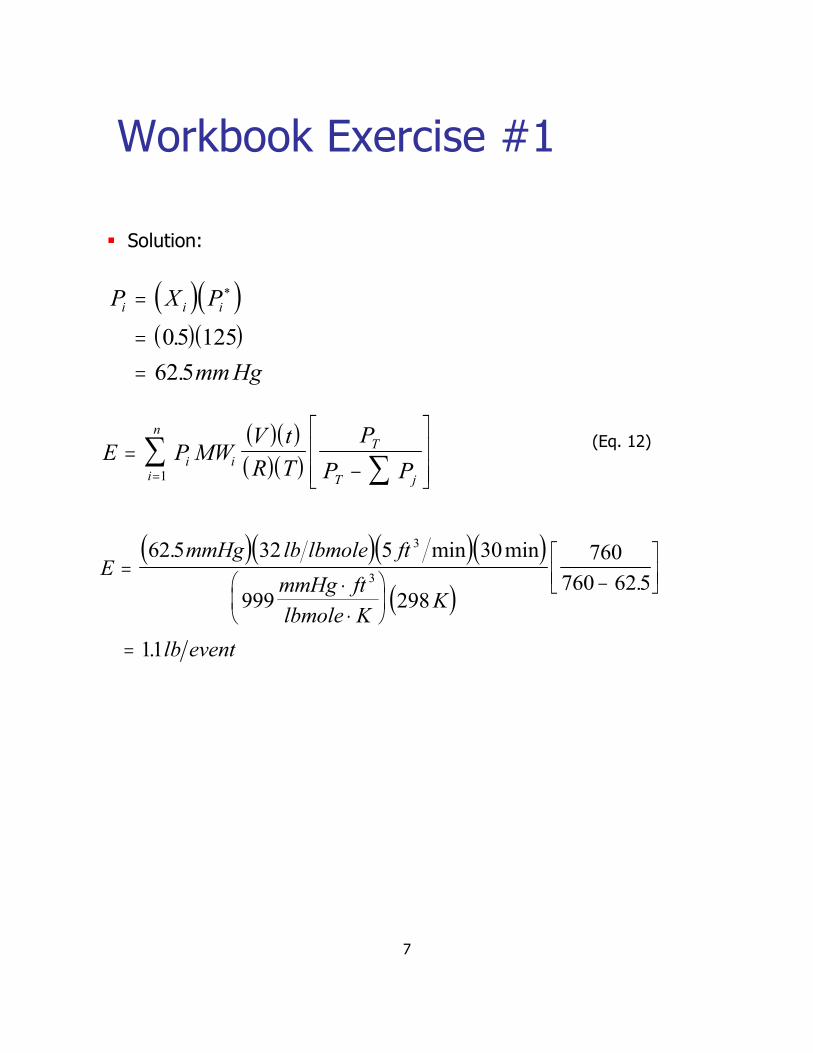
Workbook Exercise #1
Solution:
Pi PXi i
.0 5 125 62 5 mm Hg .
V tn PT (Eq. 12) E P MWii
i 1 R T PT Pj
3. min 30min 76062 5 mmHg 32 lb lbmole 5 ftE
.mmHg ft 3
298 K760 62 5
999lbmole K
11 . lb event
7

[This page intentionally left blank.]
8

Workbook Exercise #2
Objective: Calculate uncontrolled HAP
N2emissions for N2 purge of a centrifuge (CENT-1)
Data
Flowrate of N2: 500 scfm for 5 minutes
Centrifuge Temperature of vapor space: 37°C
Composition:
26 lbs H2O
81 lbs MeOH
199 lbs CHCl3
306 lbs total
9

[This page intentionally left blank.]
10

Workbook Exercise #2 (cont.)
Calculation procedure:
Step 1: Calculate x (mole fraction) and P (partial pressure) of i i
condensables. Vapor pressure P* of materials at 37°C. The vapor pressures and molecular weights are found in the data table for the case study (see Appendix C).
MateriaMateriall Mass, lbMass, lb
H2OH2O 2626
MeOHMeOH 8181
CHCl3CHCl3 199199
VaporVapor PartialPartial 25%25%pressurepressure pressurepressure saturationsaturation
MWMW lb moleslb moles xxiiP*, mmHgP*, mmHg P , mmHgP , mmHgii
P , mmHgP , mmHgii
1818 1.441.44 .26.26 4242 1212 33
3232 2.52.5 .45.45 228228 102102 2525
119.4119.4 1.71.7 .30.30 320320 9494 2424
TotalTotal 5.65.6 208 52208 52
Note that because the flowrate is >100 scfm, the emission stream must be assumed to be only 25 percent saturated.
11

[This page intentionally left blank.]
12

Workbook Exercise #2 (cont.)
Step 2: Correct flowrate for non-standard conditions.
V = 500 scfm @standard conditions: 68°F (20°C) and 1 atm
V P 11 V P 22
T1 T2
Since P1 = P2, the equation to calculate the flowrate at actual conditions simplifies to:
T1
T2V2 V1
ft3
ft3
C 37 273
273 C 20 500 529
min min
13

[This page intentionally left blank.]
14

Workbook Exercise #2 (cont.)
Step 3: Calculate uncontrolled emissions for the event.
tV
T
Pj PT
PTMW P iiE R
lb 32 / ft 529 lbmol minutes 5 mmHg 25
3 / min 760 EMeOH
760 52 3
999ft mmHg
K lbmol
K 310
EMeOH MeOH lb 4.7
lb 4. 119 mmHg 24 / ft 529 mol minutes 5 3 / min 760 ECHCl3
760
3 52
999ft mmHg
K 310 K lbmol
CHCl lb 5. 25 3
E = (7.4 lb MeOH + 25.5 lb CHCl3)
= 33 lb HAP emitted during 5-minute purge event
15

[This page intentionally left blank.]
16

Workbook Exercise #3
Objective: Calculate emissions from heating a 1,250 gal reactor that contains 750 gal of a toluene solution from 20°C to 70°C.
Data
Initial temperature (T1) = 20°C (293 K)
Final temperature (T2) = 70°C (343 K)
Reactor vapor space = 500 gallons
Toluene MW = 92 lb/lbmole
7.48 gal/ft3
999mmHg ft3
R = lb mole K
System pressure = 760 mmHg
Assume toluene is the only condensable compound
17

[This page intentionally left blank.]
18

Workbook Exercise #3 (cont.)
Solution: Use equations 18, 19, and 20 in §63.1257 of subpart GGG.
n
PT Pi ,1 i 1
E MWHAP N AVG n n ni ,2 ni ,1 (Eq. 18)
PT Pi ,2 i 1
VPT 1 1(Eq. 19) N AVG 2R T1 T2
P V P V (Eq. 20) ni ,2 ni ,1
i ,2 i ,1
RT2 RT1
Step 1: Calculate NAVG
ft 3
760mmHg500gal7 48 gal. 1 1
N AVGmmHg ft 3 293K 343K
2 999 lbmole K
0161 lbmole .
19

[This page intentionally left blank.]
20

Workbook Exercise #3 (cont.)
Step 2: Calculate toluene partial pressure. One way is to use the Antoine equation as follows (with coefficients obtained from Lange’s Handbook of Chemistry):
Blog P A
T C C
.1344 8 .log Ptoluene,20 C 6 955
20 219 48 .
.1 339
. Ptoluene,20 C 2185 mmHg
Similarly,
.1344 8 .log Ptoluene ,70 C 6 955
70 219 48 .
.2 309
. Ptoluene ,70 C 203 9 mmHg
21

[This page intentionally left blank.]
22

2
Workbook Exercise #3 (cont.)
Step 3: Calculate ni,2 – ni,1
gal 500 ft 3 .7 48 gal 203 9 mmHg 2185 mmHg. .
ni , ni ,1
3 K K343 293
mmHg999
lbmole K
ft
0 0348 lbmole .
Step 4: Calculate toluene emissions
n 760 2185 .
760 203 9 . 92lb lbmole
E lbmole lbmole 0 161 . 0 0348 .
0 99 lb tolueneemitted during heatup .
23

[This page intentionally left blank.]
Appendix F
# Data for Monitoring Example in Section 7
# Exercise to Determine Ongoing Compliance Status

[This page intentionally left blank.]

Data for Monitoring Examples
1760°F
Time
Temperature
Measured, °F Hourly Average
12:00 AM 1740 1754
12:15 AM 1760
12:30 AM 1760
12:45 AM 1754
1:00 AM 1750 1731
1:15 AM 1730
1:30 AM 1720
1:45 AM 1725
2:00 AM 1730 1743
2:15 AM 1743
2:30 AM 1750
2:45 AM 1750
3:00 AM 1752 1753
3:15 AM 1752
3:30 AM 1753
3:45 AM 1755
4:00 AM 1760 1763
4:15 AM 1762
4:30 AM 1765
4:45 AM 1766
5:00 AM 1768 1767
5:15 AM 1768
5:30 AM 1768
5:45 AM 1765
Thermal Incinerator
Temperature set during the performance test:
1

Data for Monitoring Examples (continued)
Time
Temperature
Measured, °F Hourly Average
6:00 AM 1764 1763
6:15 AM 1762
6:30 AM 1762
6:45 AM 1765
7:00 AM 1766 1768
7:15 AM 1768
7:30 AM 1768
7:45 AM 1769
8:00 AM 1770 1772
8:15 AM 1771
8:30 AM 1772
8:45 AM 1775
9:00 AM 1777 1759
9:15 AM 1740
9:30 AM 1760
9:45 AM 1760
10:00 AM 1754 1739
10:15 AM 1750
10:30 AM 1730
10:45 AM 1720
11:00 AM 1725 1737
11:15 AM 1730
11:30 AM 1743
11:45 AM 1750
12:00 PM 1750 1757
12:15 PM 1777
12:30 PM 1740
12:45 PM 1760
2

Data for Monitoring Examples (continued)
Time
Temperature
Measured, °F Hourly Average
1:00 PM 1760 1749
1:15 PM 1754
1:30 PM 1750
1:45 PM 1730
2:00 PM 1720 1730
2:15 PM 1725
2:30 PM 1730
2:45 PM 1743
3:00 PM 1750 1764
3:15 PM 1750
3:30 PM 1777
3:45 PM 1777
4:00 PM 1740 1754
4:15 PM 1760
4:30 PM 1760
4:45 PM 1754
5:00 PM 1750 1731
5:15 PM 1730
5:30 PM 1720
5:45 PM 1725
6:00 PM 1730 1743
6:15 PM 1743
6:30 PM 1750
6:45 PM 1750
7:00 PM 1777 1777
7:15 PM
7:30 PM
7:45 PM 1777
3

Data for Monitoring Examples (continued)
Temperature
Time Measured, °F Hourly Average
8:00 PM 1777
8:15 PM 1777
8:30 PM 1777
8:45 PM
9:00 PM 1777 1770
9:15 PM 1777
9:30 PM 1777
9:45 PM 1750
10:00 PM 1750 1761
10:15 PM 1777
10:30 PM 1777
10:45 PM 1740
11:00 PM 1760 1756
11:15 PM 1760
11:30 PM 1754
11:45 PM 1750
Results:
24-hour average from raw data: 1754°F 24-hour average from hourly averages: 1755°F
4

Questions and Answers
Q. Is the thermal incinerator in compliance with the operating limit?
A. No. The daily average is less than the 1760°F operating limit.
Q. Are the data availability requirements met (is there sufficient valid data)?
A. Yes. There are 2 hours during the day for which data are not available
for each 15-minute period (both of these 2 hours have measurements for
two of the 15-minute periods). For CPMS and a control device that
operates at least 4 hr/d, the MON requires data for each of the 15-minute
periods in an hour to have a valid hour of data. In addition, the MON
requires valid data for at least 75 percent of the hours in the day. The
source in our example easily meets this requirement (22/24 = 91 percent).
Q. What recordkeeping and reporting would be required for the day in this
example?
A. At a minimum, a record of the daily average is required. The MON
references subpart SS, which generally requires records of the 15-minute
(or more frequent) measurements as well. However, subpart SS also
allows a source to retain only the daily average, provided several
requirements are met. One of the requirements is that the equipment
must keep a running average, calculated hourly, of values for at least the
preceding 6 hours, and a record is required anytime this value is outside
the operating limit.
In addition, the compliance report must include a variety of information
related to the deviation (e.g., the date, the daily average, a description of
the process/CMS, HAP in the emission stream, date of the latest CMS
certification or audit, and the operating log for the day). Information
from this deviation also would be combined with information for other
deviations to generate summary statistics of the total duration of
deviations and their causes during the reporting period.
5

[This page intentionally left blank.] 6

Exercise
Suppose the data in the preceding table are for an incinerator that is used to
control emissions from a batch process that operates from 7:00 p.m. to 11:00 p.m.
on the day for which the data apply. Also assume the owner or operator has
elected to demonstrate compliance by averaging over an operating block consisting
of the entire batch cycle, and the operating limit is still 1760°F.
Question: Is the source in compliance with its operating limit?
7

[This page intentionally left blank.] 8

Answer to Exercise
Yes. The block average is okay (1769°F is greater than 1760°F). However,
for CPMS, data are required for all of the 15-minute periods in an hour to have a
valid hour of data. In addition, for a control that operates at least 4 hours per day,
valid data must be available for at least 75 percent of the hours in a day. Since the
source in this exercise has valid data for only 2 of the 4 hours of control operation
(50 percent), they have a deviation from the data availability requirement.
9

[This page intentionally left blank.]

Appendix G
# Acronyms
# Definitions
# Applicability Materials

2 [This page intentionally left blank.]

Acronyms
AMR Actual mass removal
APCD Air pollution control device
BOD Biological oxygen demand
BPV Batch process vent
BR Bottoms receiver
CAA Clean Air Act
CAR Consolidated Federal Air Rule
CCCD Centralized combustion control device
CEMS Continuous emissions monitoring system
Cl2 Chlorine
CMS Continuous monitoring system
CPMS Continuous parameter monitoring system
CPV Continuous process vent
CVS Closed-vent system
DE Design evaluation
DOT Department of Transportation
EFR External floating roof
EI Emission inventory
EIQ Emission inventory questionnaire
Fr Fraction removed (values in Table 9 to subpart G)
HAP Hazardous air pollutant
HCl Hydrogen chloride
HF Hydrogen fluoride
HON Hazardous Organic NESHAP
IFR Internal floating roof
LDAR Leak detection and repair program
MACT Maximum achievable control technology
MCPU Miscellaneous organic chemical manufacturing process unit
MTVP Maximum true vapor pressure
NAICS North American Industrial Classification System
NOCS Notification of compliance status
OLD Organic Liquid Distribution (MACT subpart EEEE)
o/o Owner or operator
P&ID Process and instrumentation diagram
PM HAP Particulate matter HAP
PMPU Pharmaceutical manufacturing process unit
POD Point of determination
PRM Planned routine maintenance
PRV Pressure relief valve
PSHAP Partially soluble HAP (listed in Table 8 to subpart FFFF)
PT Performance test
PTE Potential to emit
PUG Process unit group
PV Process vent
3

Acronyms (continued)
QA/QC Quality assurance/quality control
QIP Quality improvement program
RCRA Resource Conservation and Recovery Act
RMR Required mass removal
SCV Surge control vessel
SHAP Soluble HAP (listed in Table 9 to subpart FFFF)
SIC Standard Industrial Classification
SOCMI Synthetic organic chemical manufacturing industry
SSM Startup, shutdown, and malfunction
ST Storage tank
TOC Total organic compounds
TRE Total resource effectiveness
TSS Total suspended solids
VOC Volatile organic compounds
WMU Waste management unit
WW Wastewater
4

325 Chemical Manufacturing
N
R
u N
u N
c E
u R
u R
u E
u R
u N
u R
SIC
(
black)
)
)
( )
)
alcohol)
1997
NAICS
325
3251
32511
32512
32513
325131
325132
32518
325181
325182
325188
32519
325191
325192
325193
325199
1997 NAICS U.S. Description
Chemical Manufacturing
Basic Chemical Manufacturing
Petrochemical Manufacturing
Industrial Gas Manufacturing
Synthetic Dye and Pigment
Manufacturing
Inorganic Dye and Pigment
Manufacturing
Synthetic Organic Dye and Pigment
Manufacturing
Other Basic Inorganic Chemical
Manufacturing
Alkalies and Chlorine Manufacturing
Carbon Black Manufacturing
All Other Basic Inorganic Chemical
Manufacturing
Other Basic Organic Chemical
Manufacturing
Gum and Wood Chemical
Manufacturing
Cyclic Crude and Intermediate
Manufacturing
Ethyl Alcohol Manufacturing
All Other Basic Organic Chemical
Manufacturing
Codes
1987
*2865
*2869
2813
*2869
*2816
*2819
*2865
2812
*2816
2895
*2819
*2869
2861
*2865
*2869
*2869
*2899
1987 U.S. SIC Description
Cyclic Organic Crudes and Intermediates,
and Organic Dyes and Pigments (aromatics)
Industrial Organic Chemicals, NEC
(aliphatics)
Industrial Gases
Industrial Organic Chemicals, NEC
fluorocarbon gases)
Inorganic Pigments (except bone and lamp
Industrial Inorganic Chemicals, NEC
(inorganic dyes
Cyclic Organic Crudes and Intermediates,
and Organic Dyes and Pigments (organic
dyes and pigments
Alkalies and Chlorine
Inorganic pigments bone and lamp black
Carbon Black
Industrial Inorganic Chemicals, NEC
(except activated carbon and charcoal,
alumina, and inorganic industrial dyes)
Industrial Organic Chemicals, NEC (carbon
bisulfide)
Gum and Wood Chemicals
Cyclic Organic Crudes and Intermediates
and Organic Dyes and Pigments (except
aromatics and organic dyes and pigments
Industrial Organic Chemicals (ethyl
Industrial Organic Chemicals, NEC (except
aliphatics, carbon bisulfide, ethyl alcohol,
and fluorocarbon gases)
Chemical and Chemical Preparations, NEC
(fatty acids)
5

Plastics Material and Resin u
u
u
u
u
u
c
u
u
u
u
E
E
E
E
E
E
E
E
E
R
N
E
R
E
and Nonvulcanizable Elastomers
)
6
3252
32521
325211
325212
32522
325221
325222
3253
32531
325311
325312
325314
32532
3254
32541
325411
325412
325413
325414
3255
32551
32552
3256
Resin, Synthetic Rubber, and
Artificial and Synthetic Fibers and
Filaments Manufacturing
Resin and Synthetic Rubber
Manufacturing
Manufacturing
Synthetic Rubber Manufacturing
Artificial and Synthetic Fibers and
Filaments Manufacturing
Cellulosic Organic Fiber
Manufacturing
Noncellulosic Organic Fiber
Manufacturing
Pesticide, Fertilizer, and Other
Agricultural Chemical Manufacturing
Fertilizer Manufacturing
Nitrogenous Fertilizer Manufacturing
Phosphatic Fertilizer Manufacturing
Fertilizer (Mixing Only)
Manufacturing
Pesticide and Other Agricultural
Chemical Manufacturing
Pharmaceutical and Medicine
Manufacturing
Pharmaceutical and Medicine
Manufacturing
Medicinal and Botanical
Manufacturing
Pharmaceutical Preparation
Manufacturing
In-Vitro Diagnostic Substance
Manufacturing
Biological Product (except
Diagnostic) Manufacturing
Paint, Coating, and Adhesive
Manufacturing
Paint and Coating Manufacturing
Adhesive Manufacturing
Soap, Cleaning Compound, and
Toilet Preparation Manufacturing
2821
2822
2823
2824
2873
2874
2875
2879
2833
2834
*2835
*2835
2836
2851
*2899
2891
Plastics Materials, Synthetic and Resins,
Synthetic Rubber
Cellulosic Manmade Fibers
Manmade Organic Fibers, Except Cellulosic
Nitrogenous Fertilizers
Phosphatic Fertilizers
Fertilizers, Mixing Only
Pesticides and Agricultural Chemicals, NEC
Medicinal Chemicals and Botanical
Products
Pharmaceutical Preparations
In-Vitro and In-Vivo Diagnostic Substances
(except in-vitro diagnostic)
In-Vitro and In-Vivo Diagnostic Substances
(in-vitro diagnostic substances
Biological Products, Except Diagnostic
Substance
Paints, Varnishes, Lacquers, Enamels and
Allied Products
Chemicals and Chemical Preparations, NEC
(frit)
Adhesives and Sealants

u
u
u
c
u
u
R
E
E
R
E
E
E
N
R
Specialty Cleaners
Resin
)
and india ink)
32561
325611
325612
325613
32562
3259
32591
32592
32599
325991
325992
325998
Soap and Cleaning Compound
Manufacturing
Soap and Other Detergent
Manufacturing
Polish and Other Sanitation Good
Manufacturing
Surface Active Agent Manufacturing
Toilet Preparation Manufacturing
Other Chemical Product and
Preparation Manufacturing
Printing Ink Manufacturing
Explosives Manufacturing
All Other Chemical Product and
Preparation Manufacturing
Custom Compounding of Purchased
Resins
Photographic Film, Paper, Plate, and
Chemical Manufacturing
All Other Miscellaneous Chemical
Product and Preparation
Manufacturing
2841
*2844
2842
2843
*2844
2893
2892
3087
*3861
*2819
*2899
*3952
*3999
*7389
Soaps and Other Detergents, Except
Toilet Preparations (toothpaste)
Specialty Cleaning, Polishing, and Sanitary
Preparations
Surface Active Agents, Finishing Agents,
Sulfonated Oils, and Assistants
Perfumes, Cosmetics, and Other Toilet
Preparations (except toothpaste)
Printing Ink
Explosives
Custom Compounding of Purchased Plastics
Photographic Equipment and Supplies
(photographic films, paper, plates and
chemicals)
Industrial Inorganic Chemicals, NEC
(activated carbon and charcoal
Chemicals and Chemical Preparations, NEC
(except frit and table salt)
Lead Pencils and Art Goods (drawing inks
Manufacturing Industries, NEC (matches)
Business Services, NEC (aerosol packaging)
7

8 [This page intentionally left blank.]

Miscellaneous organic chemical manufacturing process means all equipment which collectively function to produce a product or isolated intermediate that are materials described in §63.2435(b). For the purposes of this subpart, process includes any, all or a combination of reaction, recovery, separation, purification, or other activity, operation, manufacture, or treatment which are used to produce a product or isolated intermediate. A process is also defined by the following:
(1) Routine cleaning operations conducted as part of batchoperations are considered part of the process;
(2) Each nondedicated solvent recovery operation is considered asingle process;
(3) Each nondedicated formulation operation is considered a singleprocess that is used to formulate numerous materials and/or products;
(4) Quality assurance/quality control laboratories are not consideredpart of any process; and
(5) Ancillary activities are not considered a process or part of anyprocess.
9

10 [This page intentionally left blank.]

Family of materials means a grouping of materials with the samebasic composition or the same basic end use or functionalityproduced using the same basic feedstocks with essentiallyidentical HAP emission profiles (primary constituent and relativemagnitude on a pound per product basis) and manufacturingequipment configuration. Examples of families of materialsinclude multiple grades of the same product or differentvariations of a product (e.g., blue, black, and red resins).
11

12 [This page intentionally left blank.]

Exa
mpl
e- F
amily
of M
ater
ials
U
nsat
urat
ed P
olye
ster
Res
ins
Thi
nnin
g
Rec
over
ed S
olve
nt
Rea
ctor
Res
in
Raw
Mat
eria
ls
Sol
vent
Sto
rage
Pro
du
ct
Raw
Mat
eria
ls
Em
issi
on
s E
ven
ts
HA
P
lb/b
atch
C
on
tro
l
Pol
yest
er A
Eth
ylen
e G
lyco
l C
harg
e R
eact
or
Eth
ylen
e G
lyco
l P
htha
lic A
nhyd
ride
Pht
halic
Anh
ydrid
e S
tyre
ne20
C
onde
nser
S
tyre
neS
olve
nt A
dditi
on
Sty
rene
30
N
one
Eth
ylen
e G
lyco
l E
thyl
ene
Gly
col
Pol
yest
er B
M
alei
c A
nhyd
ride
Cha
rge
Rea
ctor
M
alei
c A
nhyd
ride
Sty
rene
20
Con
dens
er
Sty
rene
Sol
vent
Add
ition
S
tyre
ne
30
Non
e P
ropy
lene
Gly
col
Pro
pyle
ne G
lyco
l
Pol
yest
er C
M
alei
c A
nhyd
ride
Cha
rge
Rea
ctor
M
alei
c A
nhyd
ride
Sty
rene
20
Con
dens
er
Sty
rene
Sol
vent
Add
ition
S
tyre
ne
30
Non
e P
ropy
lene
Gly
col
Pro
pyle
ne G
lyco
l
Pol
yest
er D
P
htha
lic A
nhyd
ride
Cha
rge
Rea
ctor
P
htha
lic A
nhyd
ride
Xyl
ene
30
Con
dens
er
Xyl
ene
Sol
vent
Add
ition
X
ylen
e 40
N
one
13
0.00
03
Con
dens
er
0.00
05
Con
dens
er
0.00
03
Con
dens
er
0.00
05
Con
dens
er
0.00
03
Con
dens
er
0.00
05
Con
dens
er
0.00
03
Con
dens
er
0.00
05
Con
dens
er

14 [This page intentionally left blank.]

Storage tank means a tank or other vessel that is used to store liquids that contain organic HAP and/or hydrogen halide andhalogen HAP and that has been assigned to an MCPU according tothe procedures in §63.2435(d). The following are not consideredstorage tanks for the purposes of this subpart:
(1) Vessels permanently attached to motor vehicles such astrucks, railcars, barges, or ships;
(2) Pressure vessels designed to operate in excess of 204.9kilopascals and without emissions to the atmosphere;
(3) Vessels storing organic liquids that contain HAP only asimpurities;
(4) Wastewater storage tanks;(5) Bottoms receivers;(6) Surge control vessels; and(7) Process tanks.
15

[This page intentionally left blank.]

Appendix H
Presenters’ Biographical#
Sketches

[This page intentionally left blank.]

B S , . ., has more than 15 years of experience in air quality consulting. She holds a
B.S. in Chemical Engineering from the University of Texas at Austin. Prior to starting her own
consulting firm (North State Engineering, Inc. [NSE]), she was employed as a senior
environmental engineer for Midwest Research Institute (MRI), where she provided technical
assistance to various divisions of EPA’s Office of Air Quality Planning and Standards (OAQPS).
She participated in the development of guidance and federal air standards such as national
emission standards for hazardous air pollutants (NESHAP) for Pharmaceuticals Production. As
principal of North State Engineering, she continues to consult to EPA in standards development
projects. She is currently a project assistant to the development of the Miscellaneous Organic
NESHAP (MON). She also provides industrial clients with air quality consulting services such
as compliance auditing, Title V permit development, regulatory applicability studies, emission
inventories, and SARA reports. She has written numerous Title V permit applications in several
states, including Illinois, Texas, and North Carolina and continues to assist in the development of
implementation plans associated with these issued permits. Ms. Shine is a registered
professional engineer in Texas and North Carolina.
D is a Research Chemical Engineer III with RTI International in Research Triangle
Park, North Carolina. He has more than 15 years experience providing technical assistance to
EPA in the development of National Emission Standards for Hazardous Air Pollutants
(NESHAP) and other regulatory development projects. Recent projects have involved NESHAP
for Pharmaceuticals Production, Pesticide Active Ingredient Production, and Miscellaneous
Organic Chemical Manufacturing. He holds a B.S. in Chemical Engineering from the University
of New Hampshire and an M.S. in Chemical Engineering from the University of Kentucky.