moment rotation characteristics of bolted aluminum beam ...
117
The copyright of this thesis rests with the University of Cape Town. No quotation from it or information derived from it is to be published without full acknowledgement of the source. The thesis is to be used for private study or non-commercial research purposes only. University of Cape Town
Transcript of moment rotation characteristics of bolted aluminum beam ...

The copyright of this thesis rests with the University of Cape Town. No
quotation from it or information derived from it is to be published
without full acknowledgement of the source. The thesis is to be used
for private study or non-commercial research purposes only.
Univers
ity of
Cap
e Tow
n

MOMENT - ROTATION CHARACTERISTICS OF BOLTED BEAM - TO -
COLUMN ALUMINIUM CONNECTIONS
BY: VANDY FRENCH
SUPERVISED BY: PROFESSOR A ZINGONI
DEPARTMENT OF CIVIL ENGINEERING,
UNIVERSITY OF CAPE TOWN
RONDEBOSCH 7701
CAPE TOWN
This thesis is submitted in partial fulfillment of the requirements for the award of the
Master of Science Degree in Engineering at the University of Cape Town
September 2009
Univers
ity of
Cap
e Tow
n

Moment – Rotation Characteristics of Bolted Beam – Column Aluminum Connections
i
Declaration
I know the meaning of plagiarism and declare that all the work in this document except
that for which intellectual property is acknowledged and referenced accordingly is mine.
Univers
ity of
Cap
e Tow
n

Moment – Rotation Characteristics of Bolted Beam – Column Aluminum Connections
ii
Acknowledgement
I would like to register my deep appreciation and profound gratitude to the Department of
Civil Engineering, University of Cape Town for the financial and moral support rendered
to me in the pursuit of my academic goals.
The guidance, advice and motivation rendered by my supervisor Professor Alphose
Zingoni proved invaluable and I am greatly honored to have worked with you and benefit
from your vast experience.
To the staff and colleagues at the Department of Civil Engineering for your friendship
and encouragement throughout my postgraduate program, I am most grateful.
To Mr. Munda Rogers and Mr. Abdul Bairoh, you are truly a beacon of strength.
The National Research Fund and the Chancellors Challenge Fund proved to be quite a
godsend without which this work would have been impossible.
To my family and especially my wife Bernadette and Daughters Nyambe and Nyanda,
you are the driving force in my life. Thoughts of you always lifts my spirit.
Univers
ity of
Cap
e Tow
n

Moment – Rotation Characteristics of Bolted Beam – Column Aluminum Connections
iii
ABSTRACT
Structural aluminum provides a unique option to engineers by virtue of both its unique
strength to weight ratio and its well known corrosion resistance properties. The
development of the Eurocode 9 provides an insight to the design of aluminum structures
based on results from various researchers worldwide. However the area of connections
remains very sparse with regards to research material as compared to steel as provided by
Eurocode 3 part 1-8. This work involves the analysis of the performance of aluminum
end plate beam – column connections with regards moment rotation behavior as well as
the main connection classification criteria, strength, stiffness and ductility. A parametric
study is done with the use of the non- linear finite elements program ADINA in which the
effects of connection geometry is observed under incremental loading.
Univers
ity of
Cap
e Tow
n

Moment – Rotation Characteristics of Bolted Beam – Column Aluminum Connections
iv
LIST OF FIGURES
Fig 1.1: Aluminum Helli- Deck under Construction on Off Shore Facility {28}
Fig 1.2: Aluminum Bridge Deck, Corbin Bridge Huntingdon, Pa. {29}
Fig 2.1: Double Angle Cleats
Fig 2.2: Flexible End Plate
Fig 2.3: Fin Plate Connection
Fig 2.4: Header Plate Connection
Fig 2.5: Bolted Flush (a) and One Way Extended End Plate Connection (b) {6}
Fig 2.6: End Plate Extended Both Ways (a), End Plate with Mini Haunch (b) {6}
Fig 2.7 Assembly Setup {14}
Fig 2.8 Transducer Locations {14}
Fig 2.9 Eurocode 9 Classification {15}
Fig 2.10 Practical cases of Connection Behavior EC 9{15}
Fig 2.11 Bjohovde Classification {1}
Fig 2.12 Single Span Sub frame from {2}
Fig 2.13 Stiffness Boundaries {16}
Fig 2.14 Connection Details {8}
Fig 2.15 T Stub Connection Geometry and Mesh {9}
Fig 2.16 T Stub Failure Modes, EC 3 Cited By {9}
Fig 2.17 Failure Modes of Aluminum T Stubs {9}
Fig 2.18 Tested Joint Geometries {10}
Fig 2.19 Plain Specimen with Drilled Hole {12}
Fig 2.20 Double Lap Joint Specimen {12}
Univers
ity of
Cap
e Tow
n

Moment – Rotation Characteristics of Bolted Beam – Column Aluminum Connections
v
Fig 2.21 Single Lap Joint {12}
Fig 2.22 Elementary loaded connection from {13
Fig 2.23 Connection failure patterns from {13}
Fig 2.24 Inner Ply Testing Configuration from {20}
Fig 2.25 Outer Ply Testing Configuration from {20}
Fig 2.26 Bearing Test Summary from {20}
Fig 2.27 Forces in End Plate Connection from {6}
Fig 3.1 Beam – Column Endplate Connection (ADINA)
Fig 3.2 Eight Node Elements {30}
Fig 3.3 Isotropic Bilinear/ Multi-linear Material Idealization {30}
Fig 3.4 Six and Fifteen Node Prism Elements {30}
Fig 3.5 Typical End Plate Mesh
Fig 3.6 Typical Bolt Mesh
Fig 3.6 Meshed Assembly Showing Colored Element Groups
Fig 4.1 Extended End Plate Geometry {14}
Fig 4.2 Moment Rotation Relationships {14}
Fig 4.3 Typical Mesh Plot of Calibration Models
Fig 4.4 Comparison of Moment Rotation Charecteristics 10mm ExtendedEnd Plate
Fig 4.5 Comparison of Moment Rotation Charecteristics 15mm Extended End Plate
Fig 4.6 Stress Plot For Loaded Assembly
Fig 4.7 Stress Band on Deformed Bolts
Fig 4.7 Stress Band on Deformed End Plate
Univers
ity of
Cap
e Tow
n

Moment – Rotation Characteristics of Bolted Beam – Column Aluminum Connections
vi
Fig 5.1 Finite Element Model Assembly with Variables
Fig 5.2 Bolting Arrangement for Flush End Plate Connections
Fig 5.3 Solid Geometry for EP Parameter
Fig 5.4 Moment – Rotation Curves for EP Parameter
Fig 5.5 Typical Connection Stress Band Plot for EP Parameter
Fig 5.6 Typical Deformed End - Plate Stress Band Plot for EP Parameter
Fig 5.7 Typical Deformed Bolt Stress Band Plot for EP Parameter
Fig 5.8 Moment – Rotation Curves for EPAB Parameter
Fig 5.9 Typical Connection Stress Band Plot for EPAB Parameter
Fig 5.10 Typical Deformed End - Plate Stress Band Plot for EPAB Parameter
Fig 5.11 Typical Deformed Bolt Stress Band Plot for EPAB Parameter
Fig 5.12 Solid Geometry for EPSW Parameter
Fig 5.13 Moment – Rotation Curves for EPSW Parameter
Fig 5.14 Typical Connection Stress Band Plot for EPSW Parameter
Fig 5.15 Typical Deformed End - Plate Stress Band Plot for EPSW Parameter
Fig 5.16 Typical Deformed Bolt Stress Band Plot for EPSW Parameter
Fig 5.17 Solid Geometry for EEP Parameter
Fig 5.18 Moment – Rotation Curves for EEP Parameter
Fig 5.19 Typical Connection Stress Band Plot for EEP Parameter
Fig 5.20 Typical Deformed End - Plate Stress Band Plot for EEP Parameter
Fig 5.21 Typical Deformed Bolt Stress Band Plot for EEP Parameter
Fig 6.1 Load Deflection Curves For 6mm End Plates
Fig 6.2 Load Deflection Curves For 8mm End Plates
Fig 6.3 Load Deflection Curves For 10mm End Plates
Fig 6.4 Load Deflection Curves For 12mm End Plates
Univers
ity of
Cap
e Tow
n

Moment – Rotation Characteristics of Bolted Beam – Column Aluminum Connections
vii
Fig 6.5 Load Deflection Curves For 16mm End Plates
Fig 6.6 Equivalent T-stub Anology for 6mmEEP and 16mmEEP Parameters
Fig 6.7 Aluminum T- Stub Failure Mechanisms from {9}
Fig 6.8 Variation of Bolt and End Plate (Bolt Hole) Stress With Displacement (10mmEP)
Fig 6.9 Variation of Bolt and End Plate (Bolt Hole) Stress With Displacement
(10mmEEP)
Fig 6.10 Variation of Bolt and End Plate (Bolt Hole) Stress With Displacement
(10mmEPSW)
Fig 6.11 Variation of Bolt and End Plate (Bolt Hole) Stress With Displacement
(10mmEPAB)
Fig 6.12 Variation of Bolt Stress With Displacement All Parameters (10mm) End Plates
Fig 6.13 Variation of Bolt Hole Stress on End Plate, All Parameters (10mm) End Plates
Fig 6.14 Stress Increase in T-Stub of EEP Parameters
Univers
ity of
Cap
e Tow
n

Moment – Rotation Characteristics of Bolted Beam – Column Aluminum Connections
viii
LIST OF TABLES
Table 1.1: Major Constituent Elements for Aluminum Alloys
Table 1.2: Element Composition of 6082 Aluminum Alloy
Table 2.1 Test Specimen Details {14}
Table 2.2 Flange to Bolt Combinations Considered in Numerical Analysis {9}
Table 2.3 Mechanical Properties of Aluminum Flange Material {9}
Table 2.4 Mechanical Properties of Aluminum Bolt Material {9}
Table 2.5 Aluminum Alloy Bolt Material from {13}
Table 2.6 Steel Bolt Materials from {13}
Table 2.7 Design Checks for End - Plate Connections {6}
Table 3.1 Finite Element Material Data
Table 4.1 HAZ Stress/Moment Variation at Tension Flange/End Plate Intersection
Table 4.2 Variation of Bolt Shank Stress with Increasing Moment
Table 5.1 Combination 1 (Effects of Flush End Plate Thickness with Grade 10.9 Steel
Bolts and un Stiffened Column Webs)
Table 5.2 Combination 2 (Effects of Aluminum 6082 T6 as Bolt Material)
Table 5.3 Combination 3 (Effects of Aluminum 6082 T6 as Column Web Stiffener
Material)
Table 5.4 Combination 4 (Effects of Extended End Plate with Varying Thicknesses,
Grade 10.9 Steel Bolts and un Stiffened Column Webs)
Table 5.5 Moment Rotation Data for EP Parameter
Table 5.6 Moment Rotation Data for EPAB Parameter
Table 5.7 Moment Rotation Data for EPSW Parameter
Univers
ity of
Cap
e Tow
n

Moment – Rotation Characteristics of Bolted Beam – Column Aluminum Connections
ix
Table 5.8 Moment Rotation Data for EEP Parameter
Table 6.1 Stress Increase in T-Stub of EEP parameters
Table 7.1 Connection Classification According To Eurocode 3
Univers
ity of
Cap
e Tow
n

Moment – Rotation Characteristics of Bolted Beam – Column Aluminum Connections
x
Table of Contents
Declaration i
Acknowledgement ii
Abstract iii
List of Figures iv
List of Tables viii
1 INTRODUCTION 1
1.1 Background 1
1.2 Applications of Structural Aluminum 1
1.3 Properties of Aluminum 3
1.4 Methodology 4
1.5 Plan of Development 5
2 LITERATURE REVIEW 7
2.1 Significance of Beam – Column connections on Structures 7
2.2 Implications of Connection Geometry on Bolted Beam – Column Connection
Performance 8
2.2.1 Simple Connections 8
2.2.2 Moment resistance Connections 11
2.2.3 Research by A.M. Coelho et al 14
2.3 Joint Classification Systems 17
2.3.1 Joint Classification System According to Eurocode 9 17
2.3.2 Joint Classification System by Bjorhovde et al 20
2.3.3 Joint Classification System by Nethercot et al 21
2.3.4 Joint Classification System by Eurocode 3 24
2.4 Seismic Considerations 28
2.5 Finite Element Analysis of Aluminum Bolted Joints 30
2.6 Fatigue Considerations in Aluminum Bolted Joints 36
2.6.1 Research by P. Lasarin et al 36
2.6.2 Research by J.M. Minguez et al 38
Univers
ity of
Cap
e Tow
n

Moment – Rotation Characteristics of Bolted Beam – Column Aluminum Connections
xi
2.7 Design Considerations for Bolted Aluminum Connections 40
2.8 Bolt Material Properties 40
2.9 Bolt Arrangements 42
2.9.1 Eurocode 9 Provisions 43
2.9.2 Research by C.C. Menzemer et al 44
2.10 Design Considerations for End – Plate Connections 47
2.11 Conclusions of Literature Review 51
2.12 Statement of Research, Justification and Aims 51
2.13 Methodology 52
3 FINITE ELEMENT MODELLING 53
3.1 General Overview of Finite Element Software Package 53
3.2 Units 53
3.3 Geometry 53
3.4 Element Groups 54
3.5 Non – Linear Material Properties 55
3.6 Meshing 56
3.7 Contact Algorithm 59
3.8 Boundary Conditions and Descretizing of Models 59
3.9 Loading and Time Step Function 59
3.10 Post – Processing 60
4 FINITE ELEMENT MODEL VALIDATION 61
4.1 Background to Previous Experimental Work 61
4.2 Model Calibration with ADINA 62
4.3 Analysis of Failure Patterns 65
5 NUMERICAL MODELLING RESULTS 69
5.1 Geometry and Cross Section Classification 69
Univers
ity of
Cap
e Tow
n

Moment – Rotation Characteristics of Bolted Beam – Column Aluminum Connections
xii
5.2 Parametric Combinations 71
5.3 Moment rotation Characteristics of Parameters 73
5.3.1 Combination 1 (EP) 73
5.3.2 Combination 2 (EPAB) 77
5.3.3 Combination 3 (EPSW) 80
5.3.4 Combination 4 (EEP) 83
6 DISCUSSION OF RESULTS 88
6.1 The Effect of Geometry on Connection Behavior 88
6.2 Equivalent T – Stub Behavior 91
6.3 Stress variations on End Plate and Bolts with Incremental Deformation 92
6.4 Stress Variations on End Plate / Tension Flange Joint 95
7 CONCLUSIONS AND RECCOMENDATIONS 98
7.1 Introduction 98
7.2 Conclusions 98
7.3 Classification of Connections 99
7.4 Recommendations 101
7.5 Future Research 101
References 102
Univers
ity of
Cap
e Tow
n
Moment – Rotation Characteristics of Bolted Beam – Column Aluminum Connections
1
CHAPTER 1
INTRODUCTION
1.1 Background
Aluminum has not been widely used as a structural material in the construction industry
when compared to steel. The need for further research in this domain is vital as it
possesses certain unique qualities which can render it useful in certain design
requirements by virtue of its properties.
1.2 Applications of Structural Aluminum
Aluminum has found use in the design and fabrication of non- structural finishes e.g.
windows, doors and guard rails, but is yet to be adopted as a dominant structural material
in the construction industry except for special cases. This becomes evident when
comparing existing Aluminum codes to steel design codes with regards to details. Of
interest in this material is the Eurocode 3, Part 1-8 (The Design of Joints) {16} which
deals with steel joints quite extensively whereas the Eurocode 9 (Design of Aluminum
Structures) {15} does not provide as much detail on the subject. Notwithstanding,
aluminum members have been utilized as structural components of temporary structures
for specified purposes taking into consideration the relative light weight of this metal and
the resulting ease of transportation and erection costs. Frames specially fabricated with
aluminum alloys have found application as scaffolding for easy erection and dismantling
of soffit support for the casting of reinforced concrete slabs due to its light weight and
therefore simple erection procedures. Aluminum alloys have also been useful in the
construction of temporary bridges on diversion works across rivers in highway
construction projects where it is desirable for a sustained flow of traffic to be maintained
or where inaccessibility makes it cumbersome for the transportation of vital assembly
components. An example of this is the access bridge at Knockquhassen, Stranraer,
Scotland (1992) as cited by (F.M. Mazzolani 1995) {13}. The advantage of its
comparatively light weight can again be made use of to release the pressure on hoisting
equipment and even airlifting to allow for a relatively simple erection process. Due to the
fact that structural steel is comparatively much more susceptible to corrosion especially
Univers
ity of
Cap
e Tow
n
Moment – Rotation Characteristics of Bolted Beam – Column Aluminum Connections
2
in the marine environment where it is rendered exposed to relatively high concentrations
of chlorides, aluminum alloys have been found to be of superior long term cost
effectiveness in the construction of various types of structures in the marine environment
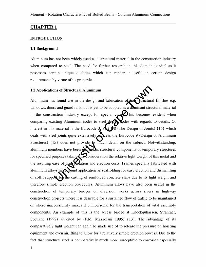
with minimal maintenance costs associated with corrosion protection. Helli-decks,
platforms and various structures on offshore oil rigs Fig 1.1 are sometimes constructed
with aluminum to take advantage of the relative corrosion resistance of the metal when
compared to steel.
Fig 1.1: Aluminum Helli deck under Construction on Off Shore Facility {28}
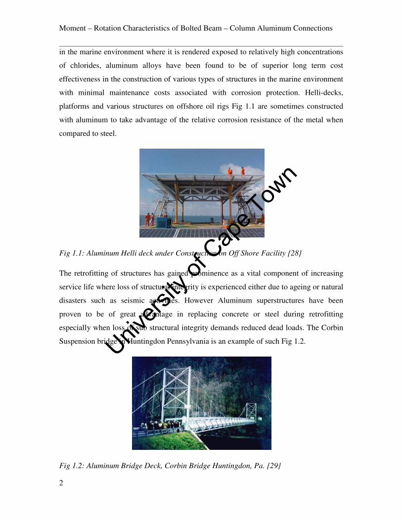
The retrofitting of structures has gained prominence as a vital component of increasing
service life where loss of structural integrity is experienced either due to ageing or natural
disasters such as seismic activities. However Aluminum superstructures have been
proven to be of great advantage in replacing concrete or steel during retrofitting
especially when loss of sub structural integrity demands reduced dead loads. The Corbin
Suspension bridge in Huntingdon Pennsylvania is an example of such Fig 1.2.
Fig 1.2: Aluminum Bridge Deck, Corbin Bridge Huntingdon, Pa. {29}
Univers
ity of
Cap
e Tow
n

Moment – Rotation Characteristics of Bolted Beam – Column Aluminum Connections
3
1.3 Properties of Aluminum
Aluminum constitutes about 8% of the earth’s crust, the principle ore from which it is
obtained being bauxite {17}. It has a weight of 2700Kg/m3 compared to 7800 Kg/m
3 for
steel and a Young’s Modulus E of 69000Mpa {17} which accounts for about a third of
that of steel 210000Mpa and as such various alloys of aluminum have been utilized in the
construction of ships superstructure and aircraft shells taking advantage of this unique
strength to weight characteristic. The stress strain idealization of aluminum is often
generated using the Ramberg-Osgood relationship which captures the material behavior
quite accurately.
The thermal expansion of aluminum is twice the value of steel and therefore due
consideration must be made in this regard where seasonal variation in temperature are
substantial. The alloying of aluminum develops added strength to the metal although this
could result in reduced corrosive resistance. An idea of the design requirements and
actual conditions of exposure is necessary in selecting a suitable alloy for the design of
structural elements. There is a tendency of welded aluminum joints to experience reduced
strength from the original material due to compression and tension stresses developed in
the heat affected zone (HAZ). The high ductility and low shear strength of aluminum has
prompted researchers to investigate and discover substantial energy dissipation
characteristics in aluminum stiffened shear panels which have been adopted in various
designs for enhanced seismic protection{18}. Table 1.1 shows the series of alloys.
Alloy Series (code) Main Alloying Constituents
1xxx ≥ 99% of Aluminium
2xxx Copper
3xxx Manganese
4xxx Silicon
5xxx Magnesium
6xxx Magnesium and Silicon
7xxx Zinc , Magnesium and /or Copper
Table 1.1: Major Constituent Elements for Aluminum Alloys
Univers
ity of
Cap
e Tow
n

Moment – Rotation Characteristics of Bolted Beam – Column Aluminum Connections
4
The variation of mechanical properties with the alloy type and treatment procedure can
be so wide ranging that it is crucial for the end use to be properly verified to match the
material properties so that the correct alloy is chosen to good effects. Up to 500Mpa
tensile strength can be attained with the 7000 series (AlZnMgCu). They are however
characterized by reduced corrosion resistance and weld ability. The same alloy series
with reduced copper percentage (ALZnMg) records strengths of 200Mpa with good
corrosion resistance and self tempering properties which render post weld strengths
nearly equal to the original tensile strength close to the HAZ. Aluminum alloys tend to
increase in strength and ductility when subjected to sub zero temperature conditions
unlike steel which becomes brittle under these same conditions.
The 6082 alloy is selected for this work due to its known high strength and suitability for
use in the construction of load carrying structures and bolted connections {13}. It is also
quite suitable for anodizing to attain enhanced corrosion resistance especially in marine
environments. The principle constituents of the 6082 alloy are magnesium and silicon.
Other trace elements are as seen in the percentages given in Table1.2. The tensile strength
of the 6082 alloy however decreases at temperatures above 100 C. Therefore care must
be taken to avoid these conditions or on the contrary, adequate design considerations
taken into account.
Alloy Percentages Other
Si Fe Cu Mn Mg Cr Zn Ti Each Total
6082 0.7 –
1.3
0.5 0.10 0.4 –
1.0
0.6 –
1.0
0.25 0.2 0.1 0.05 0.15
Table 1.2: Element Composition of 6082 Aluminum Alloy
Univers
ity of
Cap
e Tow
n

Moment – Rotation Characteristics of Bolted Beam – Column Aluminum Connections
5
1.4 Methodology
With the emergence of aluminum in the construction industry and its inclusion into the
Eurocodes {15} and the American Standards {19}, it is but fitting that the necessary
attention is focused on its connections as this forms a vital component of structural
assemblies and frames.
The main thrust of the research is to study the effects of geometry on the behavior and
failure patterns of a selected parametric array of connections. Models are developed with
the use of FEM software package ADINA to predict the dominant failure mode due to
incremental loading. Modeling involves the setting up of class 2 beam to column
cantilever assemblages with the column restrained at the top and bottom ends and chosen
with substantial stiffness relative to the beam so that minimal rotation is observed at the
column flanges and web at the point of connection through web panel shear and flange
buckling. The assemblages are connected with a combination of different jointing
techniques including extended end plates and flush end plates combined with steel and
aluminum bolts. Loading is positioned at the tip of the cantilever beam and rotation
observed for each load step whilst the connection is observed for any evidence of
distress. The welds in these assemblies are not modeled, however the relevant HAZ’s are
monitored during loading. The rotational restraints offered by these connections are
monitored whilst areas of high stress and strain are observed for failure. The ductility,
strength and stiffness are monitored and compared with existing joint classification
systems to see how the different variables affect overall connection performance The
results are analyzed with reference to the relevant design codes and conclusions
forwarded.
1.5 Plan of Development
Chapter One (Introduction) deals with introductory material with regards Aluminum and
provides a general outline of the research with the objective and plan of action of the
work laid out clearly.
Chapter Two (Literature Review) provides information and references of previous work
on bolted steel and aluminum joints, and some joint classification systems. Some Fatigue
Univers
ity of
Cap
e Tow
n

Moment – Rotation Characteristics of Bolted Beam – Column Aluminum Connections
6
and seismic considerations investigated so far are discussed. Information on design
criteria and calculations associated with the design of bolted connections are also
provided with reference to associated research work.
Chapter Three (Finite Element Modeling) reviews the framework of the software utilized
in this work ADINA, and outlines the techniques used in generating the models in terms
of geometry, mesh generation and contact algorithm amongst others.
Chapter Four (Finite Element Model Validation) describes details of Finite Element
calibration models used to validate the authenticity of the modeling technique utilized in
this work based on previous experiments by other researchers.
Chapter Five (Numerical Modeling Results) provides results obtained from Finite
Element Modeling.
Chapter Six (Discussion of Results) involves the analysis of the data obtained from the
modeling results and provides an insight to failure modes and individual connection
component responses under loading.
Chapter Seven (Conclusions and Recommendations) summarizes the conclusions and
recommendations on data made available by the finite element analysis results and
provides a classification of investigated parameters.
Univers
ity of
Cap
e Tow
n

Moment – Rotation Characteristics of Bolted Beam – Column Aluminum Connections
7
CHAPTER 2
LITERATURE REVIEW
2.1 Significance of Beam - Column Connections on Structures
Connections are a significant component of framed structures and they represent the
means by which various structural elements are assembled. The strength, stiffness and
ductility of joints have a direct consequence on the way a framed structure will behave.
Furthermore, the relative stiffness of connections is a fundamental determinant as to how
the internal forces and moments on adjacent members of the frame are distributed. It is
therefore important that connections are better understood and that continuous research is
focused on this area. The behavior of steel bolted connections has received a lot of
attention from researchers all over the world with a lot of progress being made towards
the understanding of the characteristics of various jointing techniques utilized in the
construction industry. Not much attention has been focused on the behavior of aluminum
connections. Knowledge derived from such investigations can be used to provide the
necessary confidence in the use of aluminum as a structural material. Conservative frame
analyses methods normally assume that connections are either fixed or pinned. However
the real behavior lies between these two conditions. It is thus useful that more accurate
analysis of joints is established to facilitate estimates of frame behavior that agrees well
with actual conditions on the structure and reduce cost. The importance of joints on
framed structures cannot be underestimated as connections with insufficient strength and
rigidity can cause a structure with even the most robust elements to fail prematurely
under service loads. Limited information is available in the aluminum connections area,
as such, the review will dwell largely on studies carried out on steel connections and with
a view to assess the performance of these jointing techniques on aluminum end plate
connections. Research work done on bolted aluminum lap joints to investigate the
fatigue, bolt tightening effects and bearing strength represents to a large extent , the scope
of investigations done on aluminum connections to date. These will also be discussed
widely.
Univers
ity of
Cap
e Tow
n

Moment – Rotation Characteristics of Bolted Beam – Column Aluminum Connections
8
2.2 Implications of Connection Geometry on Bolted Beam-Column Connection
Performance
2.2.1 Simple Connections
Simple connections are generally characterized by low stiffness’s and substantial rotation
capacities. Moment rotation curves depicting the various boundaries for simple, semi
rigid and rigid connections have been developed by various researchers in establishing
classification systems for beam to column joints {1}{2}. These connection types have
been deemed to match closely with design analysis of frames with joints designated and
analyzed to be pinned. Some common varieties of fabricated simple connections include
the following;
Fig 2.1: Double Angle Cleats
Double angle cleats are basically angles connected to supported beam webs by means of
bolts in assembly workshops as shown in Fig 2.1. These beam assemblies are then
transported to site and bolted on to columns through prepared clearance holes
corresponding to those on the angle cleats. They generally lack the strength of end plate
Univers
ity of
Cap
e Tow
n

Moment – Rotation Characteristics of Bolted Beam – Column Aluminum Connections
9
connections of similar nature and joint slip and angle deformation are the principal
determinants of the rotational capacity {3}. Double Angle Cleats offer negligible moment
capacities. To optimize the characteristics as simple joints, angle cleat thickness should
be as small as possible whilst bolt gauges must be kept high.
Fig 2.2: Flexible End Plate
Flexible end plates generally consist of end plates welded to the ends of supported beams
as preparation at a work shop with fitted pre bored bolt holes as seen on Fig 2.2(a). The
assembly is then taken to site and hoisted into position and bolted in place. There are two
types of flexible end plate connections and these described as follows.
Partial depth end plates are assembled as seen on Fig 2.2(c) and are normally welded
using 6, 8 or 10mm plates. The plate is welded to the web of the supported beam only,
whilst the flanges and top parts of the end plates are avoided completely {3}.There is a
tendency for some amount of curvature to be experienced on the end plate during welding
especially when using thinner plates. However this anomaly is normally corrected after
erection and tightening of the end plate assembly to the column by bolting.
(b)
(c)
(a)
Univers
ity of
Cap
e Tow
n

Moment – Rotation Characteristics of Bolted Beam – Column Aluminum Connections
10
Full depth end plates are those that extend the entire depth of the beam as shown on Fig
2.2(b). The plates are welded to the flange of the beam and in some instances this may
render the joint to be less flexible than required for design purposes which will move it
further to the semi rigid or rigid category. In these instances, care must be taken to ensure
that the thickness of the plates utilized is kept to a minimum to ensure that the shear
capacity of the joint is less than that of the beam and adequate joint flexibility is thereby
preserved.
Fig 2.3: Fin Plate Connection
Fin plates are connection arrangements with plates welded on to the supporting column
with prepared bolt holes in place. The supporting beam is then hoisted in place and the
welded fin plates are bolted on to the web of the beam as shown in Fig 2.3. Its main
advantage lies in the fact that it can accommodate connections on opposite sides of a
column minor axis quite conveniently without the problem of shared bolts. The rotation is
offered primarily by bolt-hole deformation on the fin plate or on the web of the supported
beam. Rotation can also result from the shear deformation experienced by the bolts
themselves {3}. In instances where it is desirous for the beam to frame into the web of
the supporting column , great difficulty is experienced with securing access to the bolt
holes for tightening with spanners. This may tempt the designer to increase the length of
Univers
ity of
Cap
e Tow
n

Moment – Rotation Characteristics of Bolted Beam – Column Aluminum Connections
11
the fin plate. However, if adequate calculations and design cannot justify this, it is best
avoided.
Fig 2.4: Header Plate Connection
Header plate connections comprise of plates welded on to either side of the web of the
supported beam as shown on Fig 2.4. The assembly is then bolted on to the supporting
column {4}. If the supported member is a beam then it is worthwhile to note that the
supporting beam must not be as deep as the supported beam or else top and bottom
notches will have to be introduced to allow for the necessary clearance.
2.2.2 Moment Resistant Connections
Moment connections are characterized by rigid connections with minimal rotational
capacities and high strengths .In the past, they have been designed primarily to have high
strengths with minimal consideration for other parameters. There is currently an
understanding that stiffness and ductility are worthy of serious consideration as well {6}.
The rotational stiffness and rotational capacity of moment connections are very important
Univers
ity of
Cap
e Tow
n

Moment – Rotation Characteristics of Bolted Beam – Column Aluminum Connections
12
to consider, as the capability to withstand inherent bending moment, shear force and axial
forces alone are not always adequate in analysis and design with respect to actual
performance{1}{6}. Moment connections and indeed all joints are classified largely by
the moment rotation characteristics that they exhibit when subject to loads. Various
graphs of Moment versus rotation have been developed to depict the boundaries between
different classes of joints {1} {2}. A few examples of moment connections are figs 2.5 &
2.6
Fig 2.5: Bolted Flush (a) and One Way Extended End Plate Connection (b) {6}
Fig 2.6: End Plate Extended Both Ways (a), End Plate with Mini Haunch (b) {6}
(a) (b)
(a)
(b) Univers
ity of
Cap
e Tow
n

Moment – Rotation Characteristics of Bolted Beam – Column Aluminum Connections
13
The fabrication of bolted end plate connections takes different forms depending on the
objective of the designer. Bolted end plate connections are built with plates welded on to
the flange and web of the supported beam .The end plates are then drilled to create bolt
holes and bolted on to the supporting column. The mechanism by which these joints
operate is such that the bolt tension and compression force at the bottom flange form
couples which provide the resisting moment to the applied force on the member. As such
the bolts at the top most part of the end plate experience the largest tensile force whereas
those closer to the bottom offer the lowest. The centre of rotation is usually very close
and most times assumed to be at the centre of the bottom flange of the supported beam.
The selection of the various connected members of a moment resistant connection must
be done with great consideration to avoid the need for strengthening of the column for
additional web shear resistance which in almost all cases can prove expensive. If however
this cannot be avoided sufficient measures must be taken to increase the shear capacity of
the column web to prevent premature failure. Fig 2.5 shows flush and extended end plate
connections. Flush end plate connections are usually built with the end plate terminating
at the compression and tension flanges of the beam respectively fig 2.5(a). However, for
a more robust weld to be created on the flanges, the plate is usually extended by a few
more millimeters to accommodate welds on the outside of the flanges as well. In
instances where the additional moment capacity is required, an additional row of bolts is
inserted above the tension flange of the beam on an extended portion of the end plate to
augment the bolts in tension fig 2.5(b). End Plate connections extended both ways Fig 2.6
(a) provides scope for additional rows of bolts to be placed both above and below the
tension and compression flanges of the beam thereby increasing the shear capacity by the
combined shear capacity of the bolts and bolt holes. In instances were the end plate needs
to be further stiffened if design calculations reveal that it will attain its plastic moment
capacity prematurely, the introduction of stiffeners as shown in fig 2.6 (b) serves to
improve on moment connection performance whilst also curtailing the rotational capacity
of the system. This system is used mostly where it is desirous to attain the full moment
capacity of the connected beam.
There is very little information on aluminum beam to column connections. However the
behavior of steel beam to column connections has received a lot of attention over the
Univers
ity of
Cap
e Tow
n

Moment – Rotation Characteristics of Bolted Beam – Column Aluminum Connections
14
years. Kulak et al 1997 {22}, Krishnamurthy N, (1978) {23} are among a host of
research material that formed the basis of the AISC design codes {24} at the time. The
idealization of the tension part of the steel connection as T-stubs has received a lot of
attention depicting the failure modes and factors influencing their behavior (Zoetemeijer
P, 1974). This idealization has also been investigated using aluminum T-stubs which will
be discussed as well {18}. One of the more recent materials available is the work done on
steel connections by S.M Coelho et al.
2.2.3 Research by A. M. Coelho et al
Due to the fact that deformation demands on material are particularly high at connections,
the need to investigate the performance of high strength materials on bolted connections
prompted this research by (A. M. Coelho et al 2007) with an emphasis on end plate bolts
located at the tension area of the connection. Geometry, end plate thickness to bolt
diameter ratio, end plate and bolt ductility, plate to bolt resistance ratio and weld quality
have been mentioned in some previous research by (R. Zandonini et al 1988) and (P.
Zoetermeijer 1990) as cited by (A. M. Coelho et al 2007) as principal factors influencing
the failure mechanism of such assemblages.
Combinations of seven flush (F1EP & F2EP) and extended end plate connections (EEP)
with different plate thicknesses and bolt specifications where investigated with the
combination as seen on Table 2.1.
Column Beam E/Plate Bolt
Section Grade Section Grade ���(��) Grade ∅�(��) Grade
F1EP_15_2 HE300M S355 HE320A S355 14.75 S690 24 12.9
F2EP_15_2 HE300M S355 HE320A S355 14.64 S690 24 12.9
EEP_15_2 HE300M S355 HE320A S355 14.62 S690 24 12.9
F1EP_10_2 HE300M S355 HE320A S355 10.15 S690 24 12.9
F2EP_10_2 HE300M S355 HE320A S355 10.25 S690 24 12.9
EEP_10_2a HE300M S355 HE320A S355 10.10 S690 24 12.9
EEP_10_2b HE300M S355 HE320A S355 10.10 S690 24 8.8
Table 2.1 Test Specimen Details {14}
Univers
ity of
Cap
e Tow
n

Moment – Rotation Characteristics of Bolted Beam – Column Aluminum Connections
15
Columns of HE300M were selected with HE320A beams to ensure near rigid behavior of
the columns. The (F2EP) specimens were welded in a manner designed on the
assumption that outer welds between the beam flange and end plate transfers no load
which lead to the increase of the force carried by the inner weld by a factor to account for
the eccentricities of forces on both the flange and the weld.
The geometry of the beam – column assemblage connection as tested is seen in fig 2.7.
Equipment and instrumentation set up was designed to take readings on Load, Deflection
of beam, End plate displacement, strains and Bolt deformations. The beam rotation was
calculated through readings from LVDT by the relations eqs 2.1-2.3.
� = arctan (������������.��(���)���� … … … . � 2.1
or
� = arctan (#��$%#���%#�.��(��$)��&' … … … . � 2.2)
Where
()*+= Vertical displacement
(�.�,()*+)=Beam elastic deflection given by
(�.�,()*+) = − ./�0� 12)*+36 − 5,6782)*+9
2 : … … … .2.3
Univers
ity of
Cap
e Tow
n

Moment – Rotation Characteristics of Bolted Beam – Column Aluminum Connections
16
Fig 2.7 Assembly Setup {14}
Some of the conclusions drawn from the results showed that thicker end plates lead to
increased moment resistance, initial stiffness and reduced rotation capacity. It was also
found that the 12.9 bolts exhibited low ductility thus failed with brittle fracture with low
plastic deformation under increased rotation. Bolt failure typified the collapse mode of
the 15mm End plate through tensile fracture. In the case of the 10mm End Plates, cracks
were observed close to the inner welds for the flush plate whilst the tension flange
developed cracks on the extended endplate connection.
Fig 2.8 Transducer Locations {14}
Univers
ity of
Cap
e Tow
n

Moment – Rotation Characteristics of Bolted Beam – Column Aluminum Connections
17
2.3 Joint Classification Systems
Various classification systems have been proposed aimed at predicting the behavior of
beam to column connections. Most simple frame analysis methods classify joints as
either fixed or pinned. However in most cases connections demonstrate a semi rigid
performance which lies between rigid and flexible configurations. This renders the
analysis of connections as pinned or fixed somewhat conservative in some cases, thereby
warranting the need for investigations into this particular aspect of connection behavior.
Some already existing classification systems highlight a combination of joint stiffness,
ductility and strength as their main classification criteria {1}{2}{15}{16}. (Y. Goto et al
1995/1998) examined the boundary between the rigid and semi rigid connections in
comparison with the provisions of the Eurocode 3. (R. Hasan et al 1998) developed non
linear classification model in terms of a three parameter moment rotation model including
initial stiffness, ultimate moment capacity and a shape parameter. The following
highlights some of the classification systems used in beam to column connections starting
with that proposed in the aluminum code Eurocode 9 {15}.
2.3.1 Joint Classification System According to Eurocode 9 (Design of Aluminum
Structures)
The classification of connections according to Eurocode 9 is for a match to be attained
between the analysis and structural design of the various elements of the connection.
Connection geometry and type should be able to provide results comparable to assumed
design assumptions. Their ability to match the structural properties, (rigidity, strength and
ductility) of the adjacent members provides a guide as to their categorization which is
given as fully connected and partially connected with respect to the connected members’
global behavior .
In terms of single behavior, they can also be classified with regards to Rigidity, Strength
and Ductility.
In Fully Restoring Connections, the elastic rigidity, ultimate strength and ductility either
match or are higher than that of the connected member with the force displacement curve
lying above that of the connected member. In these connection categories, the system
Univers
ity of
Cap
e Tow
n

Moment – Rotation Characteristics of Bolted Beam – Column Aluminum Connections
18
behaves as if integrated and the effects of the connection are minimal and therefore
ignored.
In Partially Restoring Connections, the elastic rigidity, ultimate strength and ductility of
the connection do not match that of the connected member and therefore the force
displacement diagram will partly fall below the curve of the member. In these instances
the effects of the joints are not to be discarded as their behavior has an influence on the
way the structure should be analyzed. Fig 2.9 shows the curves of connection/member
behavior.
Fig 2.9 Eurocode 9 Classification of Connections{15}
Connections are classified with respect to rigidity as (Rigid) Rigidity restoring
connections or (Semi-Rigid) Rigidity Non- restoring connections. These depend on the
ability of the connection to restore the initial stiffness of the connected member
notwithstanding strength and ductility.
Connections are classified with respect to strength as (Full Strength) Strength restoring
connections or (Partial Strength) Strength Non restoring connections. The ability to
Univers
ity of
Cap
e Tow
n

Moment – Rotation Characteristics of Bolted Beam – Column Aluminum Connections
19
achieve the ultimate strength of the connected member regardless of the ductility and
rigidity parameters is considered.
Connections are classified with respect to Ductility as (Ductile) Ductility restoring
connections or (Semi Ductile or Brittle) Ductility non restoring connections.
Combination of the different scenarios leads to different practical cases as seen on Fig
2.10.
Fig 2.10 Practical cases of Connection Behavior EC 9{15}
Frame structure connections are categorized as nominally pinned and built in
connections. Nominally pinned connections generally allow axial and shear loads to be
transmitted whilst bending moments are rendered insignificant. The required rotation to
Univers
ity of
Cap
e Tow
n

Moment – Rotation Characteristics of Bolted Beam – Column Aluminum Connections
20
allow full plastic hinge to develop on the member must be satisfied. Built in members
allow both axial and shear forces to be transmitted alongside bending moments as well.
2.3.2 Joint Classification System by Bjorhovde et al
Bjorhovde et al 1990 developed a non dimensional classification system taking note of
strength, stiffness and ductility criteria. The system takes into account the relationship
between reference lengths for beam elements and connection systems. The various
rotational and beam slope responses under loading are grouped into semi rigid, rigid and
flexible categories depicting their flexural behavior. Fig 2.11 is an illustration of the
classification system with the M - Ǿ curves linearized into the three main categories.
Where the x and y axes are represented by eqs 2.4-2.6
< = ==> … … � 2.4 Ø = ØØ> … … � 2.5 Ø� = =>BC �8D … … � 2.6
Reference lengths were identified that provide the initial stiffness’s of the member that
match the connection stiffness. For the rigid, semi-rigid and flexible connections these
are given as 2d, 5d and 10d respectively where d represents the depth of the beam. On
the basis of data sets evaluation by (Kishi and Chen 1986), Bjorhovde et al {1} provided
the boundary between rigid and semi rigid connections to be 2d and that between semi
rigid and flexible to be 10d.
Univ
ersity
of C
ape T
own

Moment – Rotation Characteristics of Bolted Beam – Column Aluminum Connections
21
Fig 2.11 Bjohovde Classification of Connections {1}
With regards the ultimate strength classification criterion, values of 0.2<� and 0.7<�
were deduced to be the relevant boundaries for the flexible to semi rigid range and the
semi rigid to rigid range respectively as illustrated in Fig 2.11.
Bjohovde et al {1} presented the non dimensional ductility of the connection as directly
proportional to the ratio of Mu to Mp and inversely proportional to the connections initial
stiffness.
2.3.3 Joint Classification System by Nethercot et al
A classification system was developed by Nethercot et al 1998 which took the stiffness
and the strength of beam to column connections into consideration simultaneously. It
categorized connections based on this system into fully connected, partially connected,
pin connected and non structural connections. He characterized these categories as in the
case of the fully connected connections to have high strength and stiffness, partially
connected connections to have reasonable strength and stiffness and pin connected
connections to have low strength and stiffness. Those that fail to embrace the above
characteristics were placed in the non structural category. The justification for this
classification system among others was based on the EC 3 and the Bjohovde {1}
classification systems being not always compatible with results from conventional
Univers
ity of
Cap
e Tow
n

Moment – Rotation Characteristics of Bolted Beam – Column Aluminum Connections
22
pinned and rigid frame analysis calculations for connections classified as rigid and pinned
respectively in these two systems.
The Nethercot classification system took consideration of both serviceability and ultimate
limit states for the various connection categories for which the single span sub frame
shown in Fig 2.12 was used as the reference structure. The ultimate limit state part of the
classification system is discussed in the following.
Fig 2.12 Single Span Sub frame from {2}
The criteria for the connection in the Fully Connected category require that the moment
capacity of the connection should be greater than or equal to that of the connected beam
moment capacity, and that the stiffness of the connection should be high enough to
enable the connection to develop full moment capacity. For this the connection stiffness
must not be less than K given as follows eq 2.7.
E = 38G(2 + G) /0�5� … … … . � 2.7
EIc
EIc
EIc
EIc
Lc
Lc
L
EI
Univers
ity of
Cap
e Tow
n
Moment – Rotation Characteristics of Bolted Beam – Column Aluminum Connections
23
Where G JKL EM are given by eq 2.8 - 2.9;
G = EM/0 5D … … … . � 2.8
EM = 8/0M5M … … … . � 2.9
The classification of connections into the Pinned category by Nethercot et al is based on
the assumption that the stiffness and the moment capacity of the connection should be
less than 25% of that calculated with the frame connections assumed to be rigid by
conventional frame analysis. With this analysis the connection stiffness must not exceed
K Given by eq 2.10;
E = 0.67G(2 + G) /0�5� … … … . � 2.10
This will only hold if the connection has sufficient rotation capacity with the given
stiffness to be able to fulfill this classification requirement. Thus the rotation capacity
must not be less than ѲQ,�+S for the connection to fulfill the requirements where ѲQ,�+S is
given by eq 2.11;
ѲQ,�+ST U0.344 + 0.561 V =W,�%=X,�=>,�� =X,�Y9 Z =W,�[BC … … … . � 2.11
Where
<8,� is the design moment of the span
Univers
ity of
Cap
e Tow
n

Moment – Rotation Characteristics of Bolted Beam – Column Aluminum Connections
24
<\,� is the yield moment capacity of the beam
<�,� is the ultimate moment capacity of the beam span.
Connections in the Partially Connected Connections Category represent those that fail to
fulfill the requirements of the above two but have substantial rotation capacity to qualify
them to be classified in the partially connected category. The required minimum rotation
ѲQ,�+S in this case is given by eq 2.12;
ѲQ,�+ST ]̂^̂_̂0.344 + 0.212 <8,M<8,� + 0.561 U <8,��<\,�<�,� − <\,�Z9 1
`1 + <8,M <8,�a bccccd <8,�5/0 . . � 2.12
Where
<8,M is the design moment of the connection whilst all the other parameters remain the
same.
Connections falling in the Non Structural Connections Category are those that fail to
fulfill any of the above conditions such that they tend to lack the requisite ductility and
therefore rotation capacity to attain the design condition.
2.3.4 Joint Classification System by Eurocode 3
The classification of joints according to the Eurocode 3 like many other classification
systems establishes a relationship between the properties of the connection and that of the
connected structural members. It uses this relationship as a basis for the comparison of
connection attributes and predicted behavior under global frame analysis. Unlike the
Bjorhovde classification scheme, the Eurocode 3 system does not make use of the
reference length concept thereby leaving the designer to classify connections based on his
own unique situations in terms of beam spans L especially when dealing with the
stiffness criterion.
Univers
ity of
Cap
e Tow
n

Moment – Rotation Characteristics of Bolted Beam – Column Aluminum Connections
25
Connections are classified according to stiffness as one of the three given below.
- Rigid
- Semi-Rigid
- Nominally Pinned
Rigid connections are those that exhibit high enough stiffness for the entire system to be
analyzed as a continuous one without considering the influence of the connection.
Nominally pinned connections are defined as those that do not develop significant
moments to affect the analyses of the structure whilst transmitting internal forces and
demonstrating substantial rotation capacities.
Semi- Rigid connections account for those that fail to meet the criteria of the rigid and
nominally pinned boundaries.
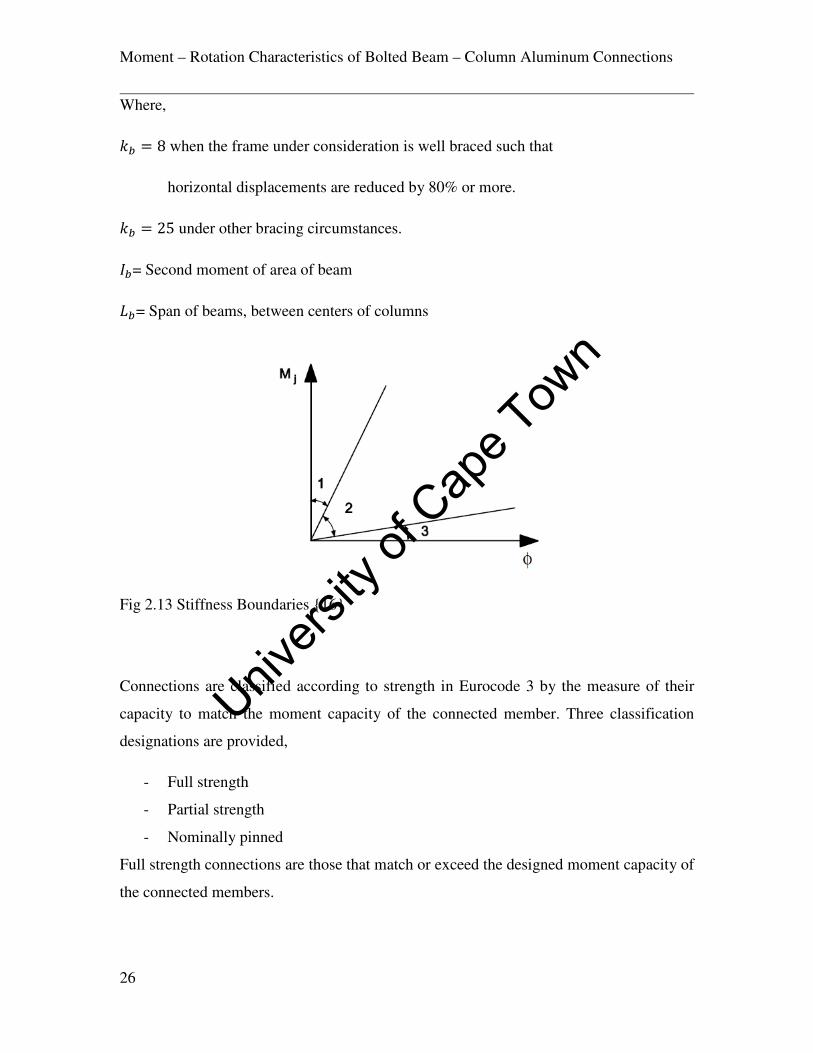
The governing factor of the stiffness classification in this scheme is the initial stiffness
ef,+S+ which is defined as the slope of the moment rotation curve on the elastic part of the
non-linear relationship with classification boundaries given by eq 2.13-2.15;
ef,+S+ ≥ h�BC�[� … … … . � 2.13 Rigid Criterion (Zone 1)
�.�BC�[� <ef,+S+ < h�BC�[� … … … . . � 2.14 Semi Rigid Criterion (Zone 2)
ef,+S+ ≤ �.�BC�[� … … … . � 2.15 Nominally pinned Criterion (Zone 3)
Univers
ity of
Cap
e Tow
n
Moment – Rotation Characteristics of Bolted Beam – Column Aluminum Connections
26
Where,
k� = 8 when the frame under consideration is well braced such that
horizontal displacements are reduced by 80% or more.
k� = 25 under other bracing circumstances.
0�= Second moment of area of beam
5�= Span of beams, between centers of columns
Fig 2.13 Stiffness Boundaries {16}
Connections are classified according to strength in Eurocode 3 by the measure of their
capacity to match the moment capacity of the connected member. Three classification
designations are provided,
- Full strength
- Partial strength
- Nominally pinned
Full strength connections are those that match or exceed the designed moment capacity of
the connected members.
Univers
ity of
Cap
e Tow
n

Moment – Rotation Characteristics of Bolted Beam – Column Aluminum Connections
27
Partial strength connections are those that fail to meet the criteria of both nominally
pinned connections and full strength connections.
Nominally pinned connections are characterized by their ability of transmitting internal
forces without developing significant moments that affect the analysis and behavior of
the structure.
In the case of the strength classification, the plastic moment capacity of the connected
member <�,�,,l8 is the governing parameter upon which the classification is based. Thus,
the joint design moment resistance <f,l8is classified based on the following eq 2.16-2.18;
<f,l8 ≥ <�,�,,l8 … … … . � 2.16 Full strength
0.25<�,�,,l8 < <f,l8 < <�,�,,l8 … … … . � 2.17 Partial Strength
<f,l8 < 0.25<�,�,,l8 … … … . � 2.18 Nominally Pinned
The advantage of the Bjorhovde classification scheme is that its reference length concept
allows the connection to be classified even without knowing the lengths of the members.
With regards to the EC 3 classification, an idea of the proportions of the frame or
connection will have to be at hand before the necessary calculations regarding
classification are carried out. The Nethercot classification scheme could prove to be even
more accurate in frames whose geometry is closely related to that upon which the scheme
is based. In terms of the strength criterion, the EC 3 is much stricter in the determination
of the boundary between full strength and Partial strength being equivalent or exceeding
the full plastic moment of the connected beam. The EC 9 scheme also places emphasis on
the comparison of the connection behavior and beam properties. However in terms of
stiffness, the classification will prove to be dependent on the member lengths as in the EC
3.
Univers
ity of
Cap
e Tow
n

Moment – Rotation Characteristics of Bolted Beam – Column Aluminum Connections
28
2.4 Seismic Considerations
The behavior of steel beam to column joints under seismic conditions has captured the
interest of researchers the world over and especially in earthquake prone areas of the
world due to catastrophic joint failure of structures during severe earthquakes. The onset
of cyclic loading conditions presents extra demands on the structural performance of the
joints in such a way that certain conditions had to be researched and devised to improve
on the cyclic behavior of these joints as these affect the global frame behavior. An
example of such work in this area (EP Popov et al 2002) is presented here.
In a bid to improve on the behavior of conventional seismic resistant connections after
they demonstrated certain weaknesses during the 1994 North ridge earth quake in los
Angeles, California, (Whitaker et al 2000) at the Pacific Earth quake Engineering
Research Centre (PEER) sited by (EP Popov et al 2002) carried out extensive research in
the area with a view to improve on the performance of these connections. The research
focused on cover plate and flange plate connections which sought to remove the plastic
hinge from the locality of the column face. As a follow up to this research, (EP Popov et
al 2002) sought to improve on the efficiency of this connection type by introducing
enhanced reliability and installation costs. The fabrication is in many ways similar to the
end plate connection, but in this case it is much more easily compatible to beams of
larger weight and dimensions. Boundary parameter values of special moment resisting
frames that separate ductile and brittle conditions as far as connections are concerned
have been proposed by (JA Swanson et al 2000) as cited by (EP Popov et al 2002) to be
0.03 radians plastic rotation when subject to plastic loading with a 20% subsequent
reduction in flexural strength. These were proposed after the Earthquake at Northridge.
The research aimed at providing a moment resistant bolted connection with substantial
ductility in seismic conditions which required minimal welding and was done in two
stages. The high strength bolts that were to be used in the fabrication were tested in the
first step and then the second stage consisted of testing of two specimen types as seen on
the Fig 2.14. In the experimentation involved in the first part of the test, the A 490 1- ¼
in. bolts were tested at the shank and the thread with specialized equipment built for this
purpose during which failure was observed at the threaded region. The ductility was also
Univers
ity of
Cap
e Tow
n

Moment – Rotation Characteristics of Bolted Beam – Column Aluminum Connections
29
tested in another form of experimentation with a constant diameter specimen obtained
from the A 490 bolt. It was observed during the experiments that the material
demonstrated outstanding ductility and the ultimate stress of 1033Mpa specified was
clarified.
W36-150 grade 50 members were used as beams and W14-283 grade 150 as columns in
the fabrication of this connection with A 490 bolts.W40-264 grade 50 members were cut
through the web to form T stubs which were then used to build single sided beam to
column connection assemblies. The stems of the t stubs were welded to the flange of the
beams and then given a pre-stress by bolting of the A 490 bolts on to the top and bottom
flange of the beam. The pre-stressed T – stub – beam assemblage was then attached to the
column by bolting the T stub flanges on to the column Flange as well as bolting the shear
tab of the column on to the beam web as shown in fig 2.14. The difference between the
two specimens in this second part of the test was in the stem of the T stubs. The first
specimen had a rectangular stem on either flange of the beam whilst the second specimen
was given a u - shaped geometry attached on both flanges of the beam. Calculations for
the design of these connections were in accordance with (G.L Kulak et al 1987) and
(AISC Manual of Steel Construction Vol. 1 1995a) as cited by (EP Popov et al 2002)
Fig 2.14 Connection Details {8}
Univers
ity of
Cap
e Tow
n

Moment – Rotation Characteristics of Bolted Beam – Column Aluminum Connections
30
Testing of the specimens was done by using horizontal and vertical frames as support for
the connection assembly with W14 x311 segments used to provide adequate rotation at
the points of connection. A hydraulic actuator attached to the end of the beam of the
assembly by means of an end plate and the floor beam served as the loading mechanism.
The specifications of the testing mechanism included a ±1558 kN load capacity and
±197mm as the displacement capacity at end of the cantilever beam column connection
assembly. Lateral displacement was controlled by a frame built at the end of the 3330mm
long cantilever frame which was also free of any axial load on the column.
The results obtained from this work shows that the cyclic loading produced a plastic
rotation of 0.0026 radian on specimen 1 without any connection failure. The assemblage
requires comparatively minimal welding and easy fabrication. The second specimen was
easily disassembled after testing which suggests beam repair and replacement of the T –
stubs as a possible remedial measure for structural repair work. The T stub component of
the connection assemblage provides low beam deformation. However (EP Popov et al
2002) recommended that further improvement could be achieved in specimen 2 by either
increasing the distance of the bolts on the T – stub stem from the column face, or totally
discarding them. The additional space required for transporting beams with prepared T –
stubs in place could also prove problematic.
2.5 Finite Element Analysis of Aluminum Bolted Joints
The research done by G.De Matteis et al {9} represents one of the closest to the research
material on aluminum beam to column connections covered in this work. The idealization
of the tension flange area of the connection as an equivalent T-stub is well analyzed and
provides an insight of the prying action and failure modes that are characteristic to this
zone.
An investigation into the behavior of aluminum T-stub joints was carried out by Matteis
G et al {9}. The non linear finite element software ABACUS was used to model the
behavior of the T-stubs based on calibration done with the help of available test results on
similar experiments carried out on steel T stubs. The research was done to highlight the
effects of mechanical properties of aluminum on T stub behavior with emphasis on the
Univers
ity of
Cap
e Tow
n

Moment – Rotation Characteristics of Bolted Beam – Column Aluminum Connections
31
parameters with significant departure from steel. The ABACUS model was developed to
simulate aluminum T- stubs subject to tensile forces and was based on experimental
results obtained from (O. Bursi et al 1997) as cited by (G De Matties et al 2000). The
geometry of the joint as tested is as shown in Fig 2.15. Along with the Finite element
model developed.
Fig 2.15 T Stub Connection Geometry and Mesh {9}
Univers
ity of
Cap
e Tow
n

Moment – Rotation Characteristics of Bolted Beam – Column Aluminum Connections
32
The model was developed with 3025 nodes and the number of elements added up to 1771
and 7535 degrees of freedom. Boundary conditions were established such that only a
quarter of the model was developed representing the global picture and to save
computational time. Both the T-stub and the bolts were modeled with 8 node elements
whilst bolt threads and washers were neglected. The bolts were however modeled using
10mm depth and 22mm diameter bodies. The developed contact elements utilized in this
model consists of isotropic coulomb model with the contact friction between the flange
and the rigid surface taken as zero whilst that between the bolt head and the flange
surface was given a coefficient of friction of µ = 0.3. A variety of material combinations
were adopted in modeling the T- stubs to capture a wide range of failure modes. AW
6082 (T4 and T6) and AW 6061 (T6) were selected for the flange due to good strength,
weld ability and corrosion resistant properties. For bolt materials, 5083, (AW 6082 T6)
and (AW 7075-T6) were used for aluminum alloy bolts, and steel bolts of 4.6 and 8.8
grades were adopted.
The combination of bolt and flange material used in the analysis is as seen in Table 2.2.
Bolt Flange
AW 5083
AW 6082 – T6
AW 7075 – T6
Steel Grade 4.6
Steel Grade 8.8
AW 6082 – T4
AW 6082 – T4
AW 6082 – T4
AW 6082 – T4
AW 6082 – T4
AW 6061 – T6
AW 6061 – T6
AW 6061 – T6
AW 6061 – T6
AW 6061 – T6
AW 6082 – T6
AW 6082 – T6
AW 6082 – T6
AW 6082 – T6
AW 6082 – T6
Table 2.2 Flange to Bolt Combinations Considered in Numerical Analysis {9}
Univers
ity of
Cap
e Tow
n

Moment – Rotation Characteristics of Bolted Beam – Column Aluminum Connections
33
Provision was made for adjusted material parameters of true stress and true strain to be
force /current area and logarithmic strain respectively due to the large deformations that
were these were given by eq 2.19-2.20;
mnQo� = ln(1 + qS6r) … … … . � 2.19
snQo� = sS6r(1 + mS6r) … … … . � 2.20
Inelastic behavior of aluminum alloys was interpreted using the model forwarded by
(Berstad T et al 1994) as cited by (G De Matties et al 2000) given as eq 2.21-2.22;
For s ≤ s� , s = /m … … … . � 2.21
For s > s� , s = s� + Gu1 − �2vw−xm�yz … … … . � 2.22
Where
s� = proportionality limit stress conventionally accepted as the elastic limit strength {�.9
G = Magnitude of strain hardening
x = Shape of the strain hardening curve
The plastic stain m� is given by eq 2.23;
m� = m − s/ … … … . � 2.23
With m being the total stain at s which is the current stress
A value of 10 was adopted for x as developed by (L. Moen et al 1999) and cited by (G
De Matties et al 2000) whereas values for G which depend on the category of aluminum
alloy in question are as seen on Table 2.3.
Univers
ity of
Cap
e Tow
n

Moment – Rotation Characteristics of Bolted Beam – Column Aluminum Connections
34
Aluminum Alloy {�.9
(|/��9)
{o,n
|/��9
G
|/��9
Kl.~. mo,n
(%)
AW 6082 – T6
AW 6061 – T6
AW 6082 – T4
288
240
162
330
300
299
80
140
200
35
16
8
8
6
12
Table 2.3 Mechanical Properties of Aluminum Flange Material {9}
Where
{�.9 = the nominal value of proof stress
{o,n= the stress
mo,n= the ultimate elongation
Kl.~.=Ramberg Osgood value
The validity of the model of inelastic material behavior was corroborated by (G De
Matties et al 2000) based on work done by (L. Moen et al 1999). Adopted bolt material as
used in the analysis is as seen on Table 2.4.
Aluminum Alloy ��.�
(�/���)
���� �/���
�
�/���
���� (%)
Aluminum Alloy Bolts
AW 5083
AW 6082 – T6
AW 7075 - T6
110
288
440
265
330
510
220
80
160
12
8
6
Steel Grade ��.�
(�/���)
���� �/���
���� Steel Bolts
4.6
8.8
240
893
400
974
8
6
Table 2.4 Mechanical Properties of Aluminum Bolt Material {9}
Univers
ity of
Cap
e Tow
n

Moment – Rotation Characteristics of Bolted Beam – Column Aluminum Connections
35
Fig 2.16 T Stub Failure Modes, EC 3 Cited By {9}
Fig 2.17 Failure Modes of Aluminum T Stubs {9}
This research was the first to analyze aluminum T-Stubs seeking to investigate the effects
of mechanical properties on the joint .The investigation found that the failure modes were
not easily distinguished amongst each other as compared to steel T- stubs and five
different failure mechanisms were identified Fig 2.17 as compared three on an equivalent
steel joint Fig 2.16. The importance of taking strain hardening into consideration was
made evident on the joints where the plastic deformation of both the flange and bolt
contribute towards collapse behavior. The post elastic behavior of aluminum T-stubs was
found to be related strongly to strain hardening and ductility properties of the alloys
unlike the case of steel connections.
Univers
ity of
Cap
e Tow
n

Moment – Rotation Characteristics of Bolted Beam – Column Aluminum Connections
36
2.6 Fatigue Considerations in Aluminum Bolted Joints
The presence of repeated or cyclic loads on structures precipitates fatigue if the fatigue
life of the material is reached under the specified conditions. This generally is
characterized by crack development and propagation until subsequent failure. Fatigue
failure tends to occur at stress levels lower than those stipulated for the specified static
conditions with minimal plastic deformation {13}.Data on Fatigue strength is normally
given in terms of S-N diagrams or Wohler curves in which the stress is plotted against
number of cycles. Substantial research on aluminum connections to investigating their
fatigue characteristics has been done.
2.6.1 Research by P Lasarin et al
A research was carried out by (P Lasarin et al 1996) to ascertain the effects of joint
geometry and other technological and environmental parameters on the failure modes of
aluminum bolted joints due to fatigue. The tested were carried out with 7020-T6 and
6061-T6 aluminum alloy plates with symmetrical double but joint. Bolts of grade A2-70
and 8.8 were used in different arrangements on over 100 samples with the intention of
obtaining different failure modes during experimentation. Geometries for the different
bolting arrangements on the different samples were done in conformity with the Italian
Standard {11} as cited by (P Lasarin et al 1996){10} with respect to the ratio of
transversal inter axis to bolt diameter and the distances from the free edges. Nominal
load ratios of R=0 and R=-1 where employed where R =sr+S sr7�⁄ . The samples were
different categories /series of aluminum alloy bolted joints each of which were utilized to
develop Wohler curves.
Univers
ity of
Cap
e Tow
n

Moment – Rotation Characteristics of Bolted Beam – Column Aluminum Connections
37
Fig 2.18 Tested Joint Geometries {10}
The data thus acquired during the laboratory work was combined with data obtained from
previous research done by another of the authors of this research (Atori et al 1995), to
provide information on similar work carried out on the 2024-T4 aluminum alloy. The
assemblies were connected by 10.9 steel bolts for the purpose of statistical analysis of the
different alloys in question with regards their fatigue behavior. (P Lasarin et al 1996)
made reference to previous research work done by (Atori et al 1995) which suggested
that the stress amplitudes of friction joints must be considered with the gross transverse
section of the plates in question. Observations made by ( D Kosteas et al 1993) where it
was observed that long life fatigue tests carried out on bolted aluminum alloys that the
predominant mode of failure was due to fretting induced cracks that usually occur outside
of the weakened area developed by the bolt holes but within the bolt grip. Abrasive
forces caused by the dissociation of oxides from the parent alloy during cyclic loading on
the metal to metal contact surfaces formed by bolted joints cause fretting which
eventually leads to fatigue failure as stated by( P Lasarin et al 1996) citing ( D Kosteas et
al 1993).
Univers
ity of
Cap
e Tow
n

Moment – Rotation Characteristics of Bolted Beam – Column Aluminum Connections
38
The investigation found that the geometric properties of the joints in terms of number of
bolts, size and arrangement had very little or no effect on the fatigue failure of the
samples.
With regards to the coefficient of friction being controlled by the presence and absence of
sand blasted surfaces, the higher friction coefficient on bearing joints with long service
life seems to help due to the friction transfer of loads in spite of low bolt tension. Higher
stress levels however precipitate cracking and subsequent reduction of the fatigue life of
sand blasted joints relative to the smoother surfaces.
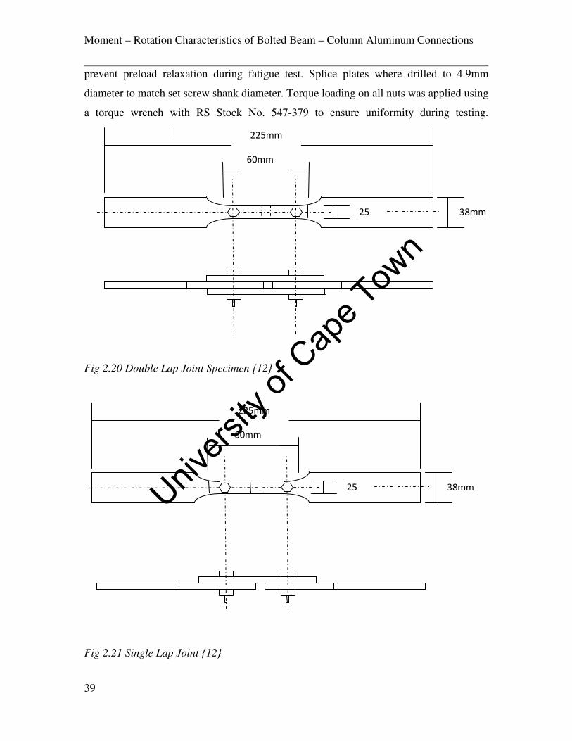
2.6.2 Research by J.M. Minguez et al
This research was aimed at investigating the effect of plate thickness and torque
tightening of bolted joints on the fatigue life of single and double lap joints.
Fig 2.19 Plain Specimen with Drilled Hole {12}
The test were carried out with a 100kN load capacity INSTRON 1332 machine with the
specimens being designed according to ASTM E466-82 standards as shown on fig 2.19.
Tests where initially done on dog bone specimens with holes drilled at the centre for the
purpose of establishing benchmarks for the experiment. The specimens were then split in
two and connected by means of double and single lap joints as shown on fig 2.20. 2m and
5mm sheet aircraft specification aluminum alloys BS L165 of T6 temper. The joints were
fabricated with 12.9M5 set screws with mild steel washers with fitted ny-lock nuts to
225mm
60mm
25 38mm
Univers
ity of
Cap
e Tow
n
Moment – Rotation Characteristics of Bolted Beam – Column Aluminum Connections
39
prevent preload relaxation during fatigue test. Splice plates where drilled to 4.9mm
diameter to match set screw shank diameter. Torque loading on all nuts was applied using
a torque wrench with RS Stock No. 547-379 to ensure uniformity during testing.
Fig 2.20 Double Lap Joint Specimen {12}
Fig 2.21 Single Lap Joint {12}
225mm
60mm
25 38mm
225mm
60mm
25 38mm
Univers
ity of
Cap
e Tow
n

Moment – Rotation Characteristics of Bolted Beam – Column Aluminum Connections
40
A frequency of 20Hz was maintained on the alternating stress purely in tension by
applying the minimum stress as small and positive.
The results obtained from this work demonstrated that torque tightening of the bolted
joints improved on the friction contact between plates and thereby reduces or removes the
bearing of bolts against bolt holes. Thus the concentration of stress is greatly reduced as
shear is transmitted through friction over a larger area of the connection thereby
increasing fatigue life. It was noted that in these scenarios, a thicker plate will perform
better under tighter bolt torque due to a gentler stress distribution.
2.7 Design Considerations for Bolted Aluminum Connections
The arrangement of bolts on a connection in terms of the end spacing and the thickness of
the plate along with the diameter of the shank of the bolt itself play a very important role
in the fabrication and assembly of bolted joints. Plate buckling, bolt failure and corrosion
are among the key failure issues that are to be contended with in ensuring that the
geometry of the system is such that it fulfills the design requirements of the expected
service loads.
2.8 Bolt Material Properties
The bolting of aluminum plates can be done by aluminum bolts, steel bolts (mild or high
strength) or stainless steel bolts. The choice of bolts is entirely dependent on the design
and environmental conditions or a combination of both. Where it is desirous to achieve a
high frictional contact between plates, it is advisable that high strength bolts are used so
that the necessary tensile and shear stresses are well accounted for by the bolt material. In
instances of severe corrosion environment where high strength bolts can be avoided,
aluminum bolts can then be made use of. The various materials usually used to fabricate
aluminum bolts are seen in Table 2.5.
Univers
ity of
Cap
e Tow
n

Moment – Rotation Characteristics of Bolted Beam – Column Aluminum Connections
41
Designation Condition
2024
5083
5056A
6082
6061
7075
T4
O
O
T6
T6
T73
Table 2.5 Aluminum Alloy Bolt Material from {13}
Ideally, the shank of the bolt usually consists of threaded and unthreaded parts. The
thickness of the plate material should normally be equal to the length of the unthreaded
shank material for optimum results {13}. Where the fabrication of friction joints is
required by design it is often standard practice to make use of either mild/high strength
steel or stainless steel as the case may be. In the case of the use of mild or high strength
steel, it is always necessary to provide some form of corrosion protection on the bolts in
order not to compromise the overall corrosion resistance of the joint as the choice of
aluminum for the structure in the first place in most cases is due to its enhanced corrosion
resistance. In these scenarios the bolts can be galvanized or coated with a protective paint
as a remedy. Table 2.6 shows the various steel bolt grades.
Steel Bolts Screw Nut
Standard 4.6 A4
5.6 5D
6.6 5S
High Strength
Stainless
8.8 6S
10.9 8G
X8CND1712
X8CNNb1811
X15CN1808
Table 2.6 Steel Bolt Materials from {13}
Univers
ity of
Cap
e Tow
n

Moment – Rotation Characteristics of Bolted Beam – Column Aluminum Connections
42
2.9 Bolt Arrangements
The arrangement of bolts on a connection system has undergone some research {20}
from which design codes have been developed to guide engineers in the design and
fabrication of aluminum joints {15} and {19}. The need to arrange bolted connections in
a manner that avoids premature failure is crucial as several key failure patterns can
emerge.
Fig 2.22 Elementary loaded connection from {13}
Consider a simplified bolted connection as shown in fig 2.22. Initially when the load
applied is increased gradually from zero, the frictional forces between the plate materials
offer the initial resistance to joint slip and are therefore responsible for bearing the load.
As the load is increased gradually, it gets to the point where it is equal to the frictional
resistance being offered by the plates in contact. At this point, any further increment of
load renders the connection to slippage at which bearing between the bolt shank and the
bolt holes becomes the dominant resisting factor of the applied load. Subsequent increase
in load will then cause joint failure due to the lesser of several possible modes depending
on the plate material properties (bearing resistance), bolt arrangement (Edge distances)
and the bolt material properties (Bearing or shear resistance){13}. The dominant failure
patterns in bolted connections in terms of localized failure are shown on fig 2.23. The
section (a) shows failure of the bolt shank in bearing. Failure can also lead to bolt hole
deformation as is seen on (b). Plate material could also be ruptured by shear failure (c).
��
��/2
��/2
Univers
ity of
Cap
e Tow
n

Moment – Rotation Characteristics of Bolted Beam – Column Aluminum Connections
43
Tension failure of the plate material (d) which causes fracture perpendicular to the line of
action of the force is also among possible failures.
Fig 2.23 Connection failure patterns from {13}
2.9.1 Eurocode 9 Provisions
The Eurocode 9{15} specifies that the minimum distance between the centre of the bolt
hole to the adjacent end of the connected plate along the direction of the load should be
normally twice the Diameter of the hole 2d0.
d0 is the diameter of the bolt hole.
In situations where a distance of 2d0 is not attainable, then a minimum of 1.2d0 is
provided by Eurocode 9{15} with the proviso that bearing stress is reduced in such a way
that the ultimate limit state design bearing force ��,B8 does not exceed the following eq
2.24-2.25;
(a). (b) (c) (d)
Univers
ity of
Cap
e Tow
n

Moment – Rotation Characteristics of Bolted Beam – Column Aluminum Connections
44
��,B8 = 9.����8n��� … … … . � 2.24
Where α is the least of
��38';��38' − ��;
����� or 1………eq 2.25
Where
��,B8 =the design bearing resistance
{o = ultimate strength of plate material
d = Bolt diameter
t = Thickness of plate
x=� = factor of safety of bolted connections
�� = Distance between bolt centers and plate end in load direction
v� = Distance between bolt centers in load direction
{o� = Ultimate Bolt strength
End distance can be increased up to 3do with no reduction of the bearing capacity.
Eurocode 9{15} further recommends that edge distances between centers of bolt holes to
the end of plate perpendicular to the direction of the load �9should not be less than 1.5 d0
Maximum edge distances are set at 40mm+ 4t in adverse weather or environmental
conditions and otherwise the larger of 12t or 150mm to satisfy local buckling
requirements.
2.9.2 Research by C.C. Menzemer et al
This research was carried out to investigate the bearing strength of three aluminum alloys
through experimental procedures to observe their behavior when subjected to tensile
loads. The three alloys utilized in this process are Aluminum Associated Designation,
Univers
ity of
Cap
e Tow
n

Moment – Rotation Characteristics of Bolted Beam – Column Aluminum Connections
45
5052-H32, 5454-H34 and 3003-H16. The research was designed to verify the bearing
strength design provisions of the Aluminum Design Manual prior to the 2000 version as
this was deemed to be too conservative by (C.C. Menzemer et al 2002){20}. The 1994
version of the Aluminum Design Manual was based on the experimental provisions for
determining bearing according to the ASTM Test Method 238 which specifies pin
loading on holes. (C.C. Menzemer et al 2002){20} brought out the deficiency in accurate
simulation of the actual bolting conditions by pointing out the absence of the effect of
bolt clamping on the plate and the plate to plate contact clamping effects both of which
have potential influence on the bearing failure of the bolt holes. In this regard the
experiments where set up taking both of these parameters into consideration.
100mm by 300mm samples where cut out of the plate materials by means of a band saw
with bolt holes placed at a distance of four times the diameter of the bolt shank from the
edge. A combination of variables were used which included the bolt diameter, the plate
thickness, Aluminum alloy material, effects of bolt washers, plate confinement
configuration and the level of torque tightness on the bolt material. 19mm diameter bolts
were used on the 6.25mm thick 5454-H34 plate and the 3.2mm thick 5052-H32 plate. A
bolt diameter of 6.25mm was used for the 1.25mm thick 3003-H16 plate and the 2.25mm
thick 5052-H32 plate. Bolt hole tolerances were set at 1.6mm clearance to fulfill design
requirements. The arrangements of the testing samples as were utilized are seen on fig.
Fig 2.24 Inner Ply Testing Configuration from {20}
4d
4in
Univers
ity of
Cap
e Tow
n

Moment – Rotation Characteristics of Bolted Beam – Column Aluminum Connections
46
Fig 2.25 Outer Ply Testing Configuration from {20}
Different torque tightened preloads were used for the various confinement specimens to
investigate their behavioral response to bearing stresses. Aluminum plates that were
bolted on either side of the steel plate as shown on fig 2.25 with loose fitted bolts were
classified on the lower bound due to expected performance whilst those that were
confined within the two flanking steel plate and snug tightened were classified on the
upper bound level. The samples were loaded in tension in a Warner-Swassey Universal
Testing Machine and all bolt holes were measured with a micrometer screw gauge prior
to testing. After the testing procedure, the bolt elongation was again measured on each
sample.
The results of the tests indicated that the samples that where configured with the inner ply
arrangement withstood higher bearing stresses compared to samples that were fitted with
loosely attached bolts. It was also discovered that bolt hole deformation under tensile
Univers
ity of
Cap
e Tow
n

Moment – Rotation Characteristics of Bolted Beam – Column Aluminum Connections
47
loading was minimized by the clamping action of the outer steel plates pressure applied
by torque tightening of the bolts. Samples that were configured with the outer ply
arrangement had higher bearing resistance with tighter snug fitted bolts as compared to
those that were fitted with loosely fitted bolts.
Fig 2.26 Bearing Test Summary from {20}
2.10 Design Considerations for End Plate Connections
End plate connections resist moments by setting up couples that are developed by tensile
forces on bolts located above the bottom flange of the beam coupled with bearing
resistance being offered by the bottom flange. The centre of rotation is normally located
at or around the centre of the bottom flange of the beam, and the bolts that are located at
the top most part of the connection normally carry the higher tensile stress {6}. In some
other cases, bolts that are located near a stiff section of the connection normally attract
higher tensile stresses.
Univers
ity of
Cap
e Tow
n

Moment – Rotation Characteristics of Bolted Beam – Column Aluminum Connections
48
Fig 2.27 Forces in End Plate Connection from {6}
Several design checks are crucial in carrying out the design of end plate beam to column
connections. This is well documented in structural steel design {6} {16}. Although in
terms of connection geometry, the resolution of forces with regards to the moment
resistance of end plate connections at the joint should basically follow the same principle
from simple resolution of couples, not much research is available in this area for
aluminum connections to actually carry out thorough design calculations. Aluminum T-
stub joints has been critically analyzed by finite element analysis {9} and this can be
represented in many respects by the tension flange - end plate joint in an equivalent
idealization. The influence of strain – hardening and alloy specifications were among the
key parameters investigated with a view of observing the failure modes on aluminum T-
stubs. However the effects of plate thickness were not monitored. Steel End plate
connection design checks as outlined in {6} are seen on table 2.7 and figure 2.27. The
tension checks involved for end plate and column flange bending as well as bolt tension
are as follows eq 2.26-2.30;
Univers
ity of
Cap
e Tow
n

Moment – Rotation Characteristics of Bolted Beam – Column Aluminum Connections
49
For complete flange yielding:
.Q = 4<�� … … … . � 2.26
For combined bolt failure and flange yielding:
.Q = 2<� + K(∑ .n�)� + K … … … . � 2.27
For bolt failure:
.Q = � .n� … … … . � 2.28
Where <� the plastic capacity of the end plate/column flange is given by:
<� = �����9v\4 … … … . � 2.29
����=Effective length of yield line
�=End plate /column flange thickness
v\=design strength of End plate/column flange
.Q=Resistance of bolt row /group
.n�= Bolt resistance capacity in tension under prying action
�= Distance between bolt centre to 20% into column root end/plate weld
K= Effective edge distance.
The effective length of the end plate/column flange yield line ���� depends on the bolt
spacing and proximity of the stiffeners or edges and varies according to the yield pattern
developed by the plate.
With regards to the checks for the column and beam webs in tension, the resistance of the
web for a row of bolts in tension is given by:
Univers
ity of
Cap
e Tow
n

Moment – Rotation Characteristics of Bolted Beam – Column Aluminum Connections
50
.n = 5n��v\ … … … . � 2.30
Where:
5n = Effective length of the web in tension considering 60 degrees spread from bolt
centre.
��=Thickness of beam /column web
v\=design strength of column /beam steel
ZONE REFERENCE CHECK
TENSION
a Bolt tension
b End plate bending
c Column flange bending
d Beam web tension
e Column web tension
f Flange to end plate weld
g Web to end plate weld
HORIZONTAL SHEAR h Column web panel shear
COMPRESSION
j Flange compression
k Beam flange weld
l Column web crushing
m Column web buckling
VERTICAL SHEAR
n Web to end plate weld
p Bolt shear
q Bolt bearing plate/flange
Table 2.7 Design Checks for End - Plate Connection {6}
As a matter of principle, these capacity checks should be done in order to satisfy design
requirement for end plate connections {6}.
Univers
ity of
Cap
e Tow
n

Moment – Rotation Characteristics of Bolted Beam – Column Aluminum Connections
51
2.11 Conclusions of Literature Review
The material covered in this review represents the general trend of research in the area of
bolted connections along with the relevant codes for both steel and aluminum. It can be
easily seen that end plate connections has received a lot of attention with regards steel.
However the research done on aluminum connections is largely restricted to lap joints.
The effect of torque tightening, bolt arrangement and spacing has received much input
which has resulted in existing codes of practice {15} {19}. Menzemer et al (1998) {26}
investigated bolted aluminum 5083 alloys to evaluate shear block failure of gusset plates
in tension. The bracing of aluminum frames with angles channels and T’s also
precipitated the research of aluminum tension members by C.C Menzemer et al (2005)
{27}. In this work members were loaded in tension and the effects of eccentricity and
bolting pattern were studied with both experimental work and some finite element
modeling. The conclusions of most of the work on aluminum has resulted in the
formulation of specifications regarding edge distances, bolt arrangement patterns and bolt
spacing to counter against block shear, bolt hole deformation and bolt shear. The specific
areas involving beam to column aluminum connections still remains sparse and warrants
investigation.
2.12 Statement of Research, Justification and Aims
The use of aluminum as a structural material is an evolving phenomenon especially in
peculiar circumstances warranting the advantage of its unique weight and corrosion
resistant properties. The aircraft manufacturing, automobile and railway industries have
already extensively made use of this material in this regard with substantial cost
effectiveness and efficiency. However, the main jointing techniques utilized in
assembling these involve single or double lap joints which have been covered to a
substantial extent by research highlighted earlier. However aluminum frames forming
parts of offshore oil rig platforms or sewage plant components involve different kinds of
connections from these as they might require extruded I sections assembled into beam
and column arrangements. Other uses including temporary and retractable bridges such
as the Aberdeen harbor in Scotland as cited by Mazzolani F.M. {13} may also require
end plate beam to column connections depending on design. The area of steel
Univers
ity of
Cap
e Tow
n
Moment – Rotation Characteristics of Bolted Beam – Column Aluminum Connections
52
connections is generously covered by Eurocode 3 part 1-8 and AISC (Allowable Stress
Design Manual) as far as these connections are concerned{16}{24}. However, designing
structures involving bolted end plate aluminum connections will prove to be rather
conservative as design codes such as Eurocode 9 and Aluminum Design Manual still
require input in this direction. This work aims at taking a step towards understanding the
moment rotation characteristics of aluminum end plate connections as may be needed for
design and use on the types of structures mentioned. The failure modes, strength,
stiffness and ductility of the parametric array analyzed forms the focal point of the
research.
2.13 Methodology
The base methodology employed in this investigation is Finite Element Modeling. The
approach involves the development of bench mark Finite Element Models against
previous work done on steel end plate connections. The accuracy of the developed
models is ascertained by comparing moment rotation curves generated by actual
experimental tests done to prove the veracity of the results. When once the results are
accurate enough, the various Finite Element Modeling techniques including element
properties, contact algorithm and boundary conditions are applied to the selected
parameters in aluminum to observe their rotational capacities strength and stiffness’s.
Univers
ity of
Cap
e Tow
n

Moment – Rotation Characteristics of Bolted Beam – Column Aluminum Connections
53
CHAPTER 3
FINITE ELEMENT MODELING
3.1 General Overview of Finite Element Software Package
The finite element software ADINA (Automatic Dynamic Incremental Non linear
Analysis) was utilized in the modeling of the different assemblies investigated in this
work. The software was developed and is a registered trade mark of K.J Bathe/ ADINA R
& D, Inc. It has a variety of elements which are available for users to choose from
depending on the analysis being carried out and has been proven to be reliable in linear
large displacement, large strain, small displacement large strain and small displacement
large strain modeling. The flexibility of this package allows the investigation of many
problems such as Eigen value analysis (linearized buckling and frequency analysis),
static, implicit and explicit dynamic analysis as well as fracture mechanics.
3.2 Units
Consistency in units is quite important when inputting data, and as such when SI units are
utilized, length force and mass are to be entered with the units Meters, Newtons and
Kilograms respectively. The models developed in this work were entered with consistent
SI units with length in millimeters and force in Newtons. As such, Young Modulus E
and stress values {are inputted and read as N/mm2.
3.3 Geometry
ADINA-M is a special feature available in this package that allows for the creation and
modification of a wide variety of solid geometry. It was used in generating the various
structural components of the model assembly. Block bodies where first generated with
this feature, followed by the creating of several cylindrical bodies for bolt shank and bolt
heads. Bolt holes where generated by creating additional cylindrical bodies within the
flanges of the column and end plates and then subtracted using the Boolean operator
provided in ADINA-M. To strike a balance between computational cost and accuracy, the
symmetry of the assemblies was taken advantage of in generating the geometry whereby
the model was developed with only half of the geometry on the positive z axis
Univers
ity of
Cap
e Tow
n
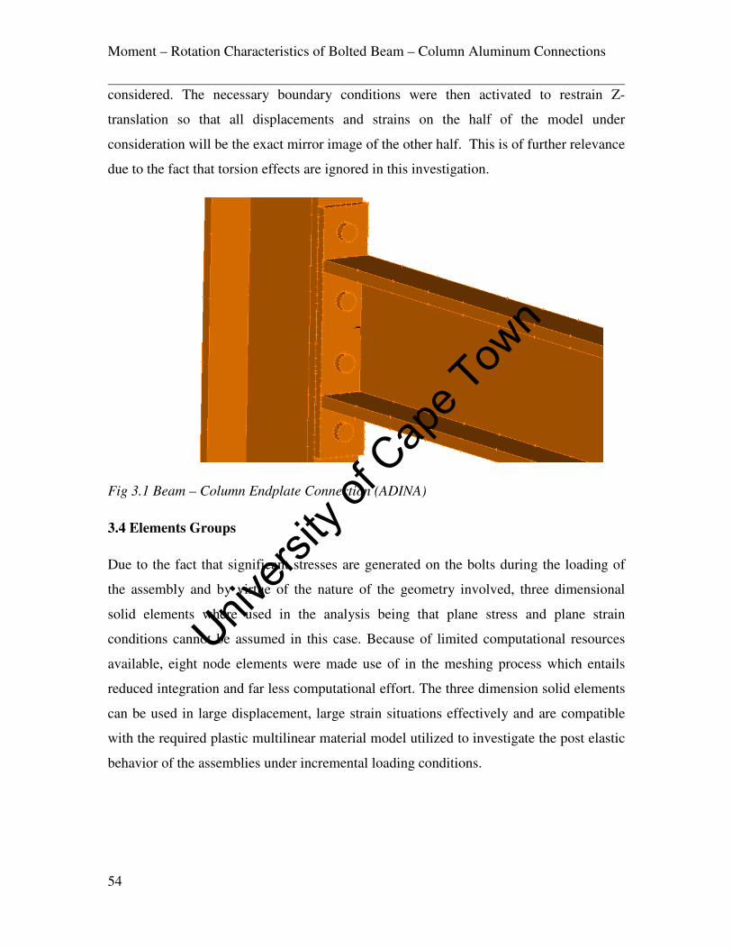
Moment – Rotation Characteristics of Bolted Beam – Column Aluminum Connections
54
considered. The necessary boundary conditions were then activated to restrain Z-
translation so that all displacements and strains on the half of the model under
consideration will be the exact mirror image of the other half. This is of further relevance
due to the fact that torsion effects are ignored in this investigation.
Fig 3.1 Beam – Column Endplate Connection (ADINA)
3.4 Elements Groups
Due to the fact that significant stresses are generated on the bolts during the loading of
the assembly and by virtue of the nature of the geometry involved, three dimensional
solid elements where used in the analysis being that plane stress and plane strain
conditions cannot be assumed in this case. Because of limited computational resources
available, eight node elements were made use of in the meshing process which entails
reduced integration and far less computational effort. The three dimension solid elements
can be used in large displacement, large strain situations effectively and are compatible
with the required plastic multilinear material model utilized to investigate the post elastic
behavior of the assemblies under incremental loading conditions.
Univers
ity of
Cap
e Tow
n

Moment – Rotation Characteristics of Bolted Beam – Column Aluminum Connections
55
Fig 3.2 Eight Node Elements {30}
Although the use of higher order elements normally yields higher accuracy, the twenty
and twenty seven node brick elements are inefficient with contact analysis which
subsequently renders tractions at contact segments to be rather inaccurate.
3.5 Non-Linear Material Properties
The plastic multi linear material formulation was adopted, with large displacement and
large strain option as the selected kinematic norm for the analysis assumptions
considering that substantial stresses were expected especially in the locality of the bolt
and bolt-hole areas of the model. Stress strain values were computed by making use of
the Ram berg Osgood material stress strain relationship model to develop the curve
defining the post elastic behavior of the materials. This material formulation is governed
by the Von misses yield condition and adopts an isotropic bilinear /multi linear strain
hardening behavior.
Univers
ity of
Cap
e Tow
n

Moment – Rotation Characteristics of Bolted Beam – Column Aluminum Connections
56
Fig 3.3 Isotropic Bilinear/ Multi-linear Material Idealization {30}
The two principal materials utilized, Aluminum 6082 T6 and Grade 10.9 steel were
inputted as seen on table 3.1 along with their poison ratios and young’s modulus values.
Young
Modulus
(Mpa)
Proof
strength ��.�
(N/mm2)
Ultimate
Strength
��(N/mm2)
Density
(Kg/m3)
Ultimate
Elongation
(%)
Aluminum
6082 T6
70000 288 330 2700 8
Grade10.9 steel 210000 893 1100 7800 6
Table 3.1 Finite Element Material Data
3.6 Meshing
Due to the relatively complex assembly geometry, the models had to be partitioned using
the Boolean operator feature available in ADINA-M so that they can be further simplified
to an extent that an acceptable mesh was obtained with the angles subtended by the
element edges within acceptable limits. As stated earlier, eight node brick elements were
Univers
ity of
Cap
e Tow
n
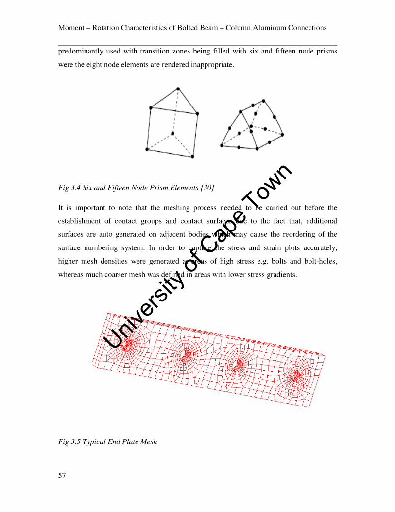
Moment – Rotation Characteristics of Bolted Beam – Column Aluminum Connections
57
predominantly used with transition zones being filled with six and fifteen node prisms
were the eight node elements are rendered inappropriate.
Fig 3.4 Six and Fifteen Node Prism Elements {30}
It is important to note that the meshing process needed to be carried out before the
establishment of contact groups and contact surfaces due to the fact that, additional
surfaces are auto generated on adjacent bodies which may cause the reordering of the
surface numbering system. In order to capture the stress and strain plots accurately,
higher mesh densities were generated at areas of high stress e.g. bolts and bolt-holes,
whereas much coarser mesh was defined in areas with lower stress gradients.
Fig 3.5 Typical End Plate Mesh
Univers
ity of
Cap
e Tow
n

Moment – Rotation Characteristics of Bolted Beam – Column Aluminum Connections
58
Fig 3.6 Typical Bolt Mesh
This technique also allows for areas of interest to be assessed quite accurately whilst
preserving the geometrical properties of the assembly in terms of dimensions and
economizing computational effort at the same time.
Fig 3.6 Meshed Assembly Showing Colored Element Groups
Univers
ity of
Cap
e Tow
n

Moment – Rotation Characteristics of Bolted Beam – Column Aluminum Connections
59
3.7 Contact Algorithm
The predominance of three D elements in the analysis warranted the use of 3-D contact
group as well throughout the modeling process with the default constraint function
contact algorithm used being that the effects of friction was neglected to cut down on
computational effort. Zero compliance factors were imputed into the modeling data to
take account of the lack of interpenetration between contact elements as the aluminum
and steel material being analyzed are sufficiently rigid enough to account for this input.
Contact between bolt head and end plates and between bolt heads and column flanges
were then defined. A much finer mesh was used to generate the bolt geometry more
accurately. As such the bolt heads were taken as the contactor with the end plate and the
column flange surfaces considered as the target surface.
3.8 Boundary Conditions and Descretizing of Models
Complete fixity was prescribed for the top and bottom edges of the attached column for
x, y and z translation, whilst a new boundary condition was prescribed to limit to zero all
translation in the z direction right across the axis of symmetry, the z axis. All rotational
degrees of freedom were rendered inactive as specified by the software literature for 3D
elements so as reduce computational effort.
3.9 Loading and Time Step Function
An incremental load was established at the extreme tip of the beams away from the joint
on the connection assembly by the automatic time step and the time function. This is
particularly useful in non- linear analysis as a sudden imposition of full loads can render
the model not to converge. Furthermore, if the range of loading condition is known
beyond which the model will collapse, then the total load can be partitioned into smaller
increments. The solution for the last converged time step corresponding to the final load
before collapse can then be observed through post processing.
Univers
ity of
Cap
e Tow
n

Moment – Rotation Characteristics of Bolted Beam – Column Aluminum Connections
60
3.10 Post Processing
All successfully completed runs of ADINA models generate a porthole file that is stored
in the temporary folder of the computer. For the solution to be obtained and analyzed
through the post processing procedure, this file with extension .por needs to be opened.
There is a wide variety of results which can be viewed by the porthole file in the ADINA
post processing module the most common being stresses, strains, displacements, traction
and reaction at specified nodes or elements depending on the area of interest. Band plots
can be generated by which the gradient of the variable of interest to the user can be
inspected and the magnitudes verified as such at various points on the assembly. ADINA
calculates results through interpolation from integration points to other points/nodes of
the element. Adjacent elements connected by a node can be evaluated into one result for
stress and strain values through this procedure termed as smoothing. The deformation of
the model can also be observed by plotting the deformed mesh. In instances where this is
rather small, the mesh plot can be modified by scaling the displacements to good effect.
Univers
ity of
Cap
e Tow
n

Moment – Rotation Characteristics of Bolted Beam – Column Aluminum Connections
61
CHAPTER 4
FINITE ELEMENT MODEL VALIDATION
4.1 Back ground To Previous Experimental Work
For the necessary confidence to be gained in the results of the Finite Elements modeling,
models were run based on experimental work done with similar connection geometry.
These were done based on the materials utilized by the researchers and the various
structural elements used. The selected experimental work was that carried out by (Coelho
A, M, and Bijlaard, F, 2006) {14} who investigated the experimental behavior of high
strength steel end plate connections. The investigation involved the use of grade S355
steel column and beam material of section HE300M and HE320A respectively. High
strength steel end plate material was made use of S690, whilst both grade 12.9 and 8.8
steel bolts of 24 mm diameter M24 were used in the fabrication of the assembly as
mentioned in Chapter 2. The moment rotation behavior of the extended end plate
connections with end plate thicknesses 10.15 and 14.75mm respectively and grade 12.9
M24 bolts were modeled with ADINA using eight node 3D element and plastic multi-
linear material idealization. The geometry of the extended end plate in this research is as
seen in Fig 4.1.
Fig 4.1 Extended End Plate Geometry {14}
Univers
ity of
Cap
e Tow
n

Moment – Rotation Characteristics of Bolted Beam – Column Aluminum Connections
62
The moment rotation curves generated from the results of the experimental work is
reproduced here Fig 4.2 for comparison with that obtained from ADINA. Of particular
interest are the two parameters which were utilized for the benchmarking process namely
EEP-15_2 and EEP_10_2a as defined by (Coelho A, M, and Bijlaard, F) {14}.
Fig 4.2 Moment Rotation Relationships {14}
The results shows greater stiffness and higher strength from the connections fabricated
with the 14.75mm end plate whilst that of the 10.15mm end plate displayed higher
ductility.
The failure mode observed for the 14.75mm end plate connection was failure of the bolts
on the extended part of the end plate connection above the tension flange, whilst for the
10.15mm extended end plate connection, there was failure of the tension flange in the
heat affected zone (HAZ) close to the weld with the end plate.
4.2 Model Calibration with ADINA
The meshed model geometry as generated with ADINA is shown on Fig 4.3. with the
loading applied at the tip of the cantilever 1300mm away from the connection as was the
case with the experimental work done by (Coelho A, M, and Bijlaard, F, 2006) {14}.
Univers
ity of
Cap
e Tow
n

Moment – Rotation Characteristics of Bolted Beam – Column Aluminum Connections
63
Fig 4.3 Typical Mesh Plot of Calibration Models
Moment rotation plots were developed using the same method as was done in this work
which was , subtracting the beam elastic deflection from observed deflections during the
incremental loading and calculating rotations in radians through simple trigonometry.The
comparison of plots so obtained with that obtained by the research experimental work are
produced in Figs 4.4 and 4.5 for comparison.
Fig 4.4 Comparison of Moment Rotation Charecteristics 10mm ExtendedEnd Plate
0
50
100
150
200
250
300
0 5 10 15 20 25 30 35
Mo
me
nt
(kN
m)
Rotation (mrad)
ADINA EEP 10.2
Coelho EEP 10.2
Univers
ity of
Cap
e Tow
n

Moment – Rotation Characteristics of Bolted Beam – Column Aluminum Connections
64
Fig 4.5 Comparison of Moment Rotation Charecteristics 15mm Extended End Plate
It can be seen from the plots that the initial stiffnesses can be calculated from the slope of
the curves at the origin quite easily. The initial stiffness on the two parameters are equal
and can be attributed almost 100% accuracy as far as the finite Element model is
concerned. In terms of the strengths of the connections, The finite element model
attained a strength of 240kNm wheras the experimental assembly failed at 260kNm for
the 10.15mm extended end plate connection.This represents 92% accuracy. In terms of
the ductility of the assembly, a 97% accuracy was achieved with the experimental
assembly failing at 29mrad and the ADINA model at 28mrad. A similar pattern was
obtained with the 14.75mm thick end plate when compared to the moment rotation curve
developed from the experimental results. In addition, the linear and nonlinear parts of the
curve followed quite closely with that of the experimental results. Being that the material
data was inputed into the ADINA based on the coupon test results as produced by
(Coelho A, M, and Bijlaard, F, 2006) {14}, the necessary confidence in the plastic multi
linear material model that was utilized in ADINA was obtained based on this correlation.
0
50
100
150
200
250
300
350
400
0 5 10 15 20 25
Mo
me
nt
(kN
m)
Rotation (mrad)
ADINA EEP 15.2
Coelho EEP 15.2
Univers
ity of
Cap
e Tow
n

Moment – Rotation Characteristics of Bolted Beam – Column Aluminum Connections
65
4.3 Analysis of Failure Patterns
The effects of the welds on the end plate connections with respect to the extent and
severity of the (HAZ) were not taken into consideration during the modeling process both
for the calibration models and the parametric study on the aluminum end plate
connections. However, the behavior of the models was monitored at sensitive areas
within the (HAZ). The tension flange/End plate weld is of particular concern for two
main reasons. Firstly, this is an area that generates large quantities of stress during the
loading process and secondly, HAZ softening accounts for substantial loss of material
strength at these points.
Fig 4.6 Stress Plot For Loaded Assembly
Fig 4.6 shows a plot of the stress across the assembly at a time step representing
126kNm, which is half of the moment capacity of the connection for EEP_10_2a.
Already large stresses have developed at the tension flange/endplate intersection as can
be seen. The failure mode as reported for this parameter by (Coelho A, M, and Bijlaard,
F, 2006) {14} is cracking at this location attributed to reduced material strength due to
HAZ softening. Data obtained from the ADINA models show the variation of stress at
this location with incremental loading up to failure as shown on Table 4.1 It can be seen
Univers
ity of
Cap
e Tow
n

Moment – Rotation Characteristics of Bolted Beam – Column Aluminum Connections
66
that stresses of 308.5MPa are recorded in the case of the 10.15mm end plate connection
at failure whilst the 14.75mm connection records stresses of up to 266.9MPa. Yield
strength of 355Mpa was inputted in the plastic bilinear material formulation to account
for beam and column materials (S355 Steel)). The failure recorded by the researchers can
easily be interpreted by these results as the stresses developed in the 10.15 mm endplate
account for 87% of the yield strength of the material. It is thus more likely that HAZ
softening on the tension flange at this position would render failure to occur at this stress
level as opposed to that recorded on the 14.75mm end plate assembly which only
accounts for 75% of the yield stress at failure.
EP_10_2a EEP_15_2
Moment(kNm) Stress(MPa) Moment (kNm) Stress(MPa)
0 0 0 0
13 14.0 13 10.7
26 36.5 26 26.4
39 60.2 39 40.4
58.5 91.1 58. 60.6
87.5 142.8 87.5 90.6
126.75 221.0 126.75 130.7
165.75 253.4 165.75 171.8
204.75 269.5 204.75 204.0
243.75 291.9 243.75 226.6
260 308.5 282.75 246.2
321.75 259.7
351 266.9
Table 4.1 HAZ Stress Moment Variation at Tension Flange/End Plate Intersection
In the case of the variation of bolt stresses with incremental loading, Coelho A, M, and
Bijlaard, F, 2006) {14} observed that the 14.75mm end plate connection failed by bolt
rupture at the extended end plate section of the assembly. Table 4.2 shows the variation
of bolt shank stress with increasing moment up to failure for the two parameters. At
failure, the 14.75mm end plate connections attain stresses of op to 1249.22MPa as
compared to 1198.05MPa in the case of the 10.15mm end plate connection. It is thus easy
to see why the predominant failure mode during experimentation was bolt failure on the
thicker end plate.
Univers
ity of
Cap
e Tow
n

Moment – Rotation Characteristics of Bolted Beam – Column Aluminum Connections
67
EEP_10_2a EEP_15_2
Moment(kNm) Stress(MPa) Moment (kNm) Stress(MPa)
0 0 0 0
13 11.72 13 10.9
26 48.93 26 134.0
39 219.78 39 255.71
58.5 336.03 58. 388.58
87.5 510.55 87.5 589.93
126.75 738.15 126.75 862.31
165.75 916.16 165.75 1107.11
204.75 946.65 204.75 1204.76
243.75 1176.46 243.75 1211.98
260 1198.05 282.75 1221.43
321.75 1235.38
351 1249.22
Table 4.2 Variation of Bolt Shank Stress with Increasing Moment
Fig 4.7 Stress Band on Deformed Bolts
Univers
ity of
Cap
e Tow
n
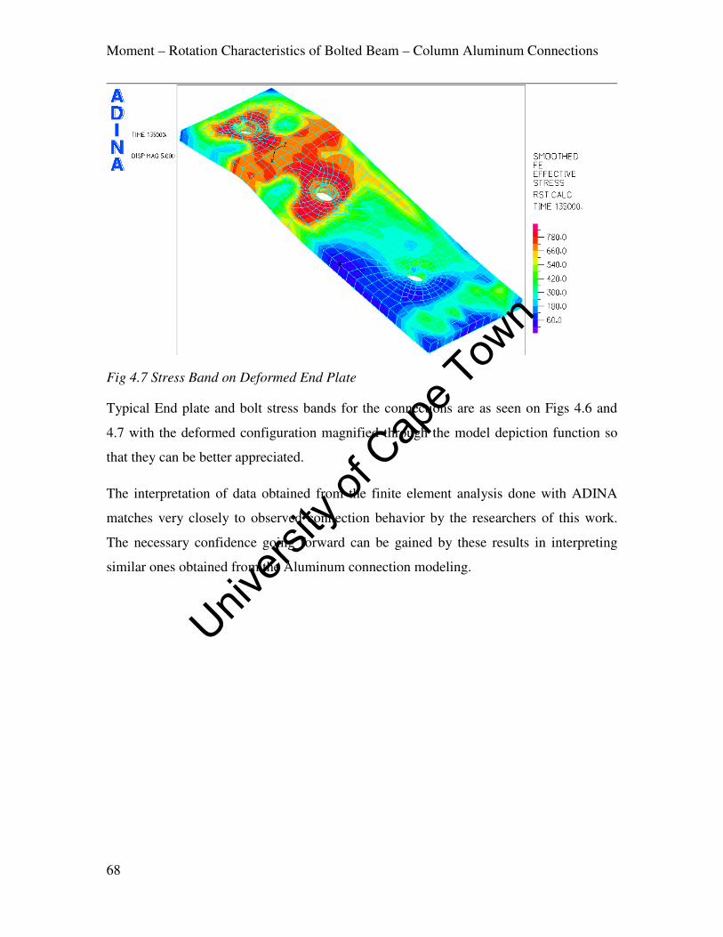
Moment – Rotation Characteristics of Bolted Beam – Column Aluminum Connections
68
Fig 4.7 Stress Band on Deformed End Plate
Typical End plate and bolt stress bands for the connections are as seen on Figs 4.6 and
4.7 with the deformed configuration magnified through the model depiction function so
that they can be better appreciated.
The interpretation of data obtained from the finite element analysis done with ADINA
matches very closely to observed connection behavior by the researchers of this work.
The necessary confidence going forward can be gained by these results in interpreting
similar ones obtained from the Aluminum connection modeling.
Univers
ity of
Cap
e Tow
n

Moment – Rotation Characteristics of Bolted Beam – Column Aluminum Connections
69
CHAPTER 5
NUMERICAL MODELLING RESULTS
5.1 Geometry and Cross - Section Classification
Fig 5.1 shows the geometry of a typical assembly as generated by the Finite Element
Models. As can be seen, complete fixity was defined for the top and bottom ends of the
columns. The point of application of the load is 1m away from the connection locality
thereby creating the requisite lever arm for generating moment. The column depth is
substantially greater than that of the beam thereby creating a much stiffer member. All
variable components such as end plate, bolts and web stiffeners are as seen labeled.
Fig 5.1 Finite Element Model Assembly with Variables
The layout of bolt holes in terms of edge spacing and bolt hole diameter was done in
compliance with the provisions of Eurocode 9 such that the spacing is not less than
2.0L6where L6is the bolt hole diameter and does not exceed 12� or 150mm, where � is
Univers
ity of
Cap
e Tow
n

Moment – Rotation Characteristics of Bolted Beam – Column Aluminum Connections
70
the thickness of the thinner outer connected plate. This serves as a control for local
buckling requirements. The layout is shown on Fig 5.2.
Fig 5.2 Bolting Arrangement for Flush End Plate Connections
Beam and column cross section classification as outlined in Eurocode 9 was carried out
to ascertain the susceptibility of the elements to local buckling. This also serves as a basis
of determining the ultimate moment of resistance of the beam which is crucial
information in accordance with joint classification schemes as connection strength
classification, as highlighted in chapter 2 is a measure of the moment resistance of the
connection with respect to that of the connected beam. Slenderness parameter values, ß
for the beam flange and web are 3.67 and 4 respectively. In the case of the column, the ß
values are 3.67 and 5.97 respectively. ɛ is given by the following relation eq 5.1;
ɛ = �9���' … … … . eq 5.1
The cross section classification boundaries as provided by Eurocode 9 being ß�, ß9 and
ß3 for internal and outstand elements render both the beam and column members to class
2. This applies as the 6082 T6 alloy is among the heat treated variety, and as such
Univers
ity of
Cap
e Tow
n
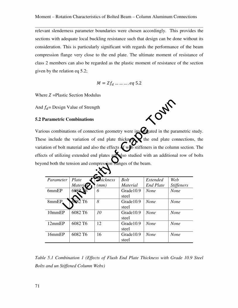
Moment – Rotation Characteristics of Bolted Beam – Column Aluminum Connections
71
relevant slenderness parameter boundaries were chosen accordingly. This provides the
sections with adequate local buckling resistance such that design can be done without its
consideration. This is particularly significant with regards the performance of the beam
compression flange very close to the end plate. The ultimate moment of resistance of
class 2 members can also be regarded as the plastic moment of resistance of the section
given by the relation eq 5.2;
< = �{8 … … … . � 5.2
Where � =Plastic Section Modulus
And {8= Design Value of Strength
5.2 Parametric Combinations
Various combinations of connection geometry were investigated in the parametric study.
These include the variation of end plate thickness in the end plate connections, the
variation of bolt material and also the effects of web stiffeners in the column section. The
effects of utilizing extended end plates are also studied with an additional row of bolts
beyond both the tension and compression flanges of the beam.
Table 5.1 Combination 1 (Effects of Flush End Plate Thickness with Grade 10.9 Steel
Bolts and un Stiffened Column Webs)
Parameter Plate
Material
Thickness
(mm)
Bolt
Material
Extended
End Plate
Web
Stiffeners
6mmEP 6082 T6 6 Grade10.9
steel
None None
8mmEP 6082 T6 8 Grade10.9
steel
None None
10mmEP 6082 T6 10 Grade10.9
steel
None None
12mmEP
6082 T6 12 Grade10.9
steel
None None
16mmEP
6082 T6 16 Grade10.9
steel
None None
Univers
ity of
Cap
e Tow
n
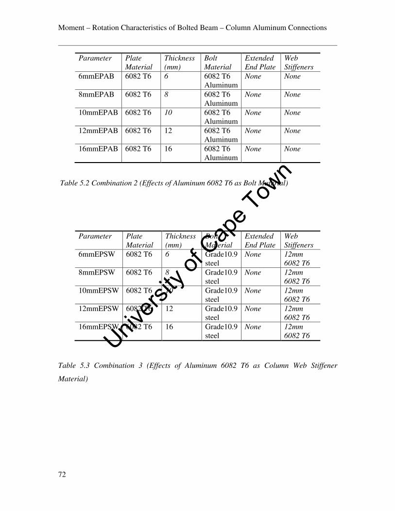
Moment – Rotation Characteristics of Bolted Beam – Column Aluminum Connections
72
Table 5.2 Combination 2 (Effects of Aluminum 6082 T6 as Bolt Material)
Table 5.3 Combination 3 (Effects of Aluminum 6082 T6 as Column Web Stiffener
Material)
Parameter Plate
Material
Thickness
(mm)
Bolt
Material
Extended
End Plate
Web
Stiffeners
6mmEPAB 6082 T6 6 6082 T6
Aluminum
None None
8mmEPAB 6082 T6 8 6082 T6
Aluminum
None None
10mmEPAB 6082 T6 10 6082 T6
Aluminum
None None
12mmEPAB
6082 T6 12 6082 T6
Aluminum
None None
16mmEPAB
6082 T6 16 6082 T6
Aluminum
None None
Parameter Plate
Material
Thickness
(mm)
Bolt
Material
Extended
End Plate
Web
Stiffeners
6mmEPSW 6082 T6 6 Grade10.9
steel
None 12mm
6082 T6
8mmEPSW 6082 T6 8 Grade10.9
steel
None 12mm
6082 T6
10mmEPSW 6082 T6 10 Grade10.9
steel
None 12mm
6082 T6
12mmEPSW
6082 T6 12 Grade10.9
steel
None 12mm
6082 T6
16mmEPSW
6082 T6 16 Grade10.9
steel
None 12mm
6082 T6 Univers
ity of
Cap
e Tow
n

Moment – Rotation Characteristics of Bolted Beam – Column Aluminum Connections
73
Table 5.4 Combination 4 (Effects of Extended End Plate with Varying Thicknesses,
Grade 10.9 Steel Bolts and un Stiffened Column Webs)
5.3 Moment Rotation Characteristics of Parameters
5.3.1 Combination 1 (EP)
Five different end plate thicknesses were utilized in developing the geometry of the Finite
Element model on this parameter Fig 5.3. The results of the load displacement
relationship are as given on Table 5.5.
Fig 5.3 Solid Geometry for EP Parameter
Parameter Plate
Material
Thickness
(mm)
Bolt
Material
Extended
End Plate
Web
Stiffeners
6mmEEP 6082 T6 6 Grade10.9
steel
6mm 6082
T6
None
8mmEEP 6082 T6 8 Grade10.9
steel
8mm 6082
T6
None
10mmEEP 6082 T6 10 Grade10.9
steel
10mm
6082 T6
None
12mmEEP
6082 T6 12 Grade10.9
steel
12mm
6082 T6
None
16mmEEP
6082 T6 16 Grade10.9
steel
16mm
6082 T6
None
Univers
ity of
Cap
e Tow
n

Moment – Rotation Characteristics of Bolted Beam – Column Aluminum Connections
74
6mmEP 8mmEP 10mmEP 12mmEP 16mmEP
M
(kNm)
Ѳmrad M
(kNm)
Ѳmrad M
(kNm)
Ѳmrad M
(kNm)
Ѳmrad M
(kNm)
Ѳmrad
0 0 0 0 0 0 0 0 0 0
1 0.71 1 0.71 1 0.64 1 0.58 1 0.49
2 2.39 2 2.19 2 2.08 2 1.70 2 1.23
3 3.61 3 3.35 3 3.17 3 2.59 3 1.86
4.5 5.47 4.5 5.05 4.5 4.76 4.5 3.89 4.5 2.82
6.75 8.82 6.75 7.70 6.75 7.15 6.75 5.84 6.75 4.26
9.75 16.75 9.75 12.21 9.75 10.53 9.75 8.52 9.75 6.28
12.75 36.54 12.75 20.61 12.75 14.62 12.75 11.56 12.75 8.54
15.75 107.17 15.75 41.07 15.75 20.79 15.75 15.48 15.75 11.19
18.75 99.26 18.75 32.34 18.75 21.61 18.75 14.41
21.75 102.66 21.75 32.92 21.75 18.37
24.75 61.57 24.75 23.56
27.75 30.6
30.75 41.42
Table 5.5 Moment Rotation Data for EP Parameter
From the Moment – Rotation plots Fig 5.4 the lowest value for connection strength
15.75kNm, was recorded from the 6mmEP model, with a maximum rotation in excess of
100mrad. The 16mmEP parameter recorded the highest strength attaining a moment of
30.75kNm but was however characterized by limited rotation capacity of 41.42mrad. The
curves generated by the FEM results were relatively smooth with the elastic and post
elastic portions evident. Connection strength and stiffness increased with end plate
thickness but however resulted in reduced ductility.
Univers
ity of
Cap
e Tow
n

Moment – Rotation Characteristics of Bolted Beam – Column Aluminum Connections
75
Fig 5.4 Moment – Rotation Curves for EP Parameter
Stress band plots were generated for a typical model within this parameter to show both
the buckling configuration and the stress propagation around the area of the connection as
shown on Fig 5.5. The stress band plots of the end plate and the bolts can also be seen on
Fig 5.6 and 5.7.
Fig 5.5 Typical Connection Stress Band Plot for EP Parameter
0
5
10
15
20
25
30
35
0 20 40 60 80 100 120
Mo
me
nt
(kN
m)
Rotation (mrad)
10mmEP
12mmEP
16mmEP
8mmEP
6mmEP
Univers
ity of
Cap
e Tow
n

Moment – Rotation Characteristics of Bolted Beam – Column Aluminum Connections
76
Fig 5.6 Typical Deformed End - Plate Stress Band Plot for EP Parameter
It can be seen from the plots that the bolt closest to the tension flange of the beam
developed the greatest magnitude of stress of within the region of 950MPa, whereas the
end plate developed stresses within the range of 330MPa with the highest stress recorded
at the bolt hole closest to the tension flange.
Fig 5.7 Typical Deformed Bolt Stress Band Plot for EP Parameter
Univers
ity of
Cap
e Tow
n

Moment – Rotation Characteristics of Bolted Beam – Column Aluminum Connections
77
5.3.2 Combination 2 (EPAB)
One of the main advantages of aluminum as a structural material as documented by
various researchers and by virtue of its material properties is its superior corrosion
resistance as compared to steel. It is however noteworthy that aluminum alloys such as
6082 T6, which is the primary material property utilized in this research is characterized
by yield strength Fy within the range of 330 MPa. This is well within the yield strength
values of some mild steel materials. This parameter investigates the use of aluminum
bolts in the same geometrical configuration as in Combination 1. The method utilized in
generating the geometry and mesh is the same as in Combination 1and the response is as
seen on Table 5.6.
6mmEPAB 8mmEPAB 10mmEPAB 12mmEPAB 16mmEPAB
M
(kNm)
Ѳmrad M
(kNm)
Ѳmrad M
(kNm)
Ѳmrad M
(kNm)
Ѳmrad M
(kNm)
Ѳmrad
0 0 0 0 0 0 0 0 0 0
0.4 0.586 0.5 0.653 0.5 0.66 0.7 0.78 0.4 0.17
0.9 1.34 1.125 1.54 1.125 1.53 1.57 1.80 0.8 0.45
1.95 2.91 2.438 3.34 2.438 3.32 3.41 3.92 1.2 0.68
3.15 4.75 3.938 5.58 3.938 5.39 5.51 6.73 1.8 1.03
4.35 7.11 5.438 10.02 5.438 7.95 7.61 13.92 2.7 1.54
5.55 11.65 6.938 20.74 6.938 13.32 9.71 37.99 3.9 2.24
6.75 20.87 7.688 32.12 8.418 23.43 10.43 74,65 5.1 2.96
7.35 29.96 6.3 3.73
7.5 4.55
8.7 5.44
9.9 6.41
Table 5.6 Moment Rotation Data for EPAB Parameter
Univers
ity of
Cap
e Tow
n
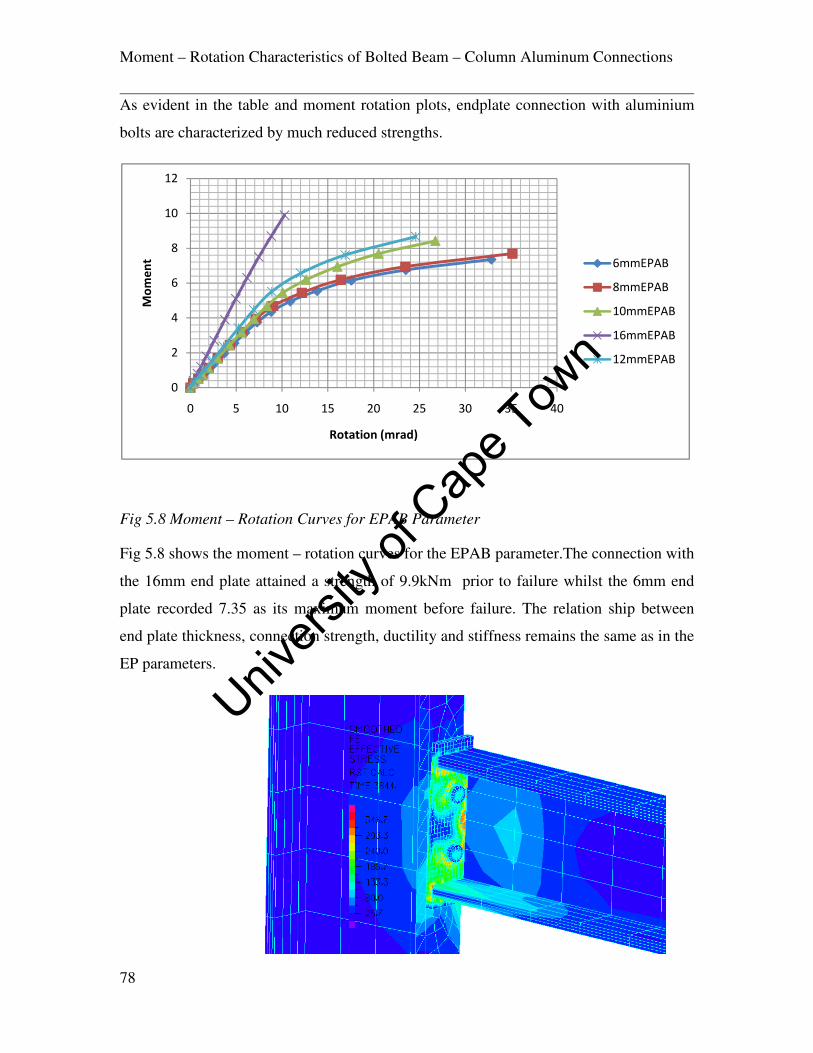
Moment – Rotation Characteristics of Bolted Beam – Column Aluminum Connections
78
As evident in the table and moment rotation plots, endplate connection with aluminium
bolts are characterized by much reduced strengths.
Fig 5.8 Moment – Rotation Curves for EPAB Parameter
Fig 5.8 shows the moment – rotation curves for the EPAB parameter.The connection with
the 16mm end plate attained a strength of 9.9kNm prior to failure whilst the 6mm end
plate recorded 7.35 as its maximum moment before failure. The relation ship between
end plate thickness, connection strength, ductility and stiffness remains the same as in the
EP parameters.
0
2
4
6
8
10
12
0 5 10 15 20 25 30 35 40
Mo
me
nt
Rotation (mrad)
6mmEPAB
8mmEPAB
10mmEPAB
16mmEPAB
12mmEPAB
Univers
ity of
Cap
e Tow
n

Moment – Rotation Characteristics of Bolted Beam – Column Aluminum Connections
79
Fig 5.9 Typical Connection Stress Band Plot for EPAB Parameter
Fig 5.10 Typical Deformed End - Plate Stress Band Plot for EPAB Parameter
The lower yield strength aluminum bolts, failed quite prematurely leaving other
components of the connection namely, endplate, column web and flange with
comparatively low stresses below their ultimate capacities.A typical band plots of the
stress on the endplate, bolts, beam and column webs are as seen on Fig 5.9, 5.10 and
5.11.
Fig 5.11 Typical Deformed Bolt Stress Band Plot for EPAB Parameter
Univers
ity of
Cap
e Tow
n

Moment – Rotation Characteristics of Bolted Beam – Column Aluminum Connections
80
5.3.3 Combination 3 (EPSW)
12mm Aluminum 6086 T6 tension and compression stiffeners were included into the
geometrical configuration Fig 5.12 and the resulting moment rotation characteristics is as
seen on Table 5.7.
Fig 5.12 Solid Geometry for EPSW Parameter
6mmEPSW 8mmEPSW 10mmEPSW 12mmEPSW 16mmEPSW
M
(kNm)
Ѳmrad M
(kNm)
Ѳmrad M
(kNm)
Ѳmrad M
(kNm)
Ѳmrad M
(kNm)
Ѳmrad
0 0 0 0 0 0 0 0 0 0
1 0.46 1 0.71 1 0.62 1 0.62 1.5 0.87
2 2.26 2 1.90 2 1.77 2 1.56 3 1.87
3 3.48 3 2.86 3 2.66 3 2.35 4.5 2.82
4.5 5.30 4.5 4.32 4.5 3.99 4.5 3.53 6.73 4.35
6.75 8.73 6.75 6.63 6.75 6.03 6.75 5.30 10.12 6.96
9.75 17.47 9.75 10.38 9.75 8.90 9.75 7.73 14.62 11.41
12.75 40.47 12.75 17.39 12.75 12.57 12.75 10.48 19.12 18.09
15.75 104.67 15.75 33.26 15.75 18.33 15.75 14.13 23.62 29.98
18.75 75.98 18.75 28.48 18.75 20.35 28.12 53.65
21.75 59.31 21.75 32.70
24.75 69.92
Table 5.7 Moment Rotation Data for EPSW Parameter
Univers
ity of
Cap
e Tow
n

Moment – Rotation Characteristics of Bolted Beam – Column Aluminum Connections
81
Fig 5.13 Moment – Rotation Curves for EPSW Parameter
The 16mm end plate connection 16mmEPSW attained strength of 28.12kNm in this case,
whilst the 6mmEPSW recorded up to 15.75kNm before failure. Furthermore, the same
relationship as in the other parameters with regards end plate thickness, strength, ductility
and stiffness held sway Fig 5.13.
Fig 5.14 Typical Connection Stress Band Plot for EPSW Parameter
0
5
10
15
20
25
30
0 50 100 150
Mo
me
nt
(kN
m)
Rotation (mrad)
10mmEPSW
12mmEPSW
16mmEPSW
6mmEPSW
8mmEPSW
Univers
ity of
Cap
e Tow
n
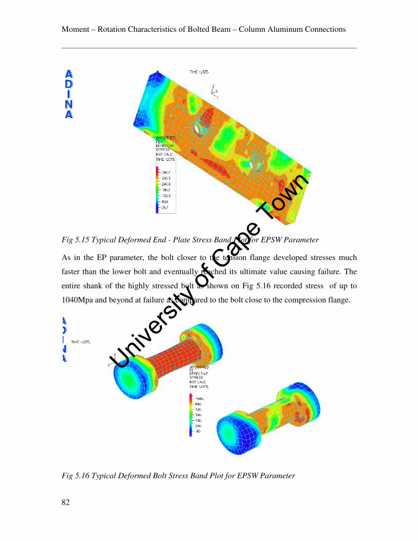
Moment – Rotation Characteristics of Bolted Beam – Column Aluminum Connections
82
Fig 5.15 Typical Deformed End - Plate Stress Band Plot for EPSW Parameter
As in the EP parameter, the bolt closer to the tension flange developed stresses much
faster than the lower bolt and eventually reached its ultimate value causing failure. The
entire shank of the highly stressed bolt as shown on Fig 5.16 recorded stress of up to
1040Mpa and beyond at failure as compared to the bolt close to the compression flange.
Fig 5.16 Typical Deformed Bolt Stress Band Plot for EPSW Parameter
Univers
ity of
Cap
e Tow
n

Moment – Rotation Characteristics of Bolted Beam – Column Aluminum Connections
83
5.3.4 Combination 4 (EEP)
An additional row of bolts was generated beyond both the tension and compression
flanges to see the amount of strength gained in terms of the increase in the moment
capacity of the connection. This was done in line with the provisions of Eurocode 9 and
Aluminum Design Manual {15} and {19} with regards edge and end spacing Fig 5.17.
The resulting stresses developed by the bolts and the end plate as well as the flanges and
webs of the connected members of the assembly were again monitored under incremental
loading. Table 5.8 shows the resulting moment rotation characteristics of this
arrangement.
Fig 5.17 Solid Geometry for EEP Parameter
Univers
ity of
Cap
e Tow
n

Moment – Rotation Characteristics of Bolted Beam – Column Aluminum Connections
84
6mmEEP 8mmEEP 10mmEEP 12mmEEP 16mmEEP
M
(kNm)
Ѳmrad M
(kNm)
Ѳmrad M
(kNm)
Ѳmrad M
(kNm)
Ѳmrad M
(kNm)
Ѳmrad
0 0 0 0 0 0 0 0 0 0
1 0.47 1 0.45 1 0.45 1 0.41 1 0.38
2 1.24 2 1.07 2 1.05 2 0.89 2 0.79
3 1.87 3 1.62 3 1.59 3 1.34 3 1.19
4.5 2.81 4.5 2.43 4.5 2.40 4.5 2.01 4.5 1.79
6.75 4.22 6.75 3.65 6.75 3.62 6.75 3.02 6.75 2.68
9.75 6.17 9.75 5.29 9.75 5.24 9.75 4.37 9.75 3.88
12.75 8.42 12.75 7.02 12.75 6.91 12.75 5.72 12.75 5.07
15.75 11.56 15.75 8.97 15.75 8.67 15.75 7.09 15.75 6.28
18.75 16.70 18.75 11.36 18.75 10.64 18.75 8.51 18.75 7.51
21.75 25.08 21.75 14.65 21.75 12.89 21.75 10.09 21.75 8.78
24.75 39.05 24.75 19.83 24.75 15.57 24.75 11.95 24.75 10.13
27.75 57.47 27.75 28.31 27.75 19.01 27.75 14.30 27.75 11.64
30.75 44.55 30.75 24.11 30.75 17.50 30.75 13.39
33.75 31.93 33.75 21.97 33.75 15.56
36.75 28.96 36.75 18.57
39.75 23.66
40.00 24.22
Table 5.8 Moment Rotation Data for EEP Parameter
Univers
ity of
Cap
e Tow
n
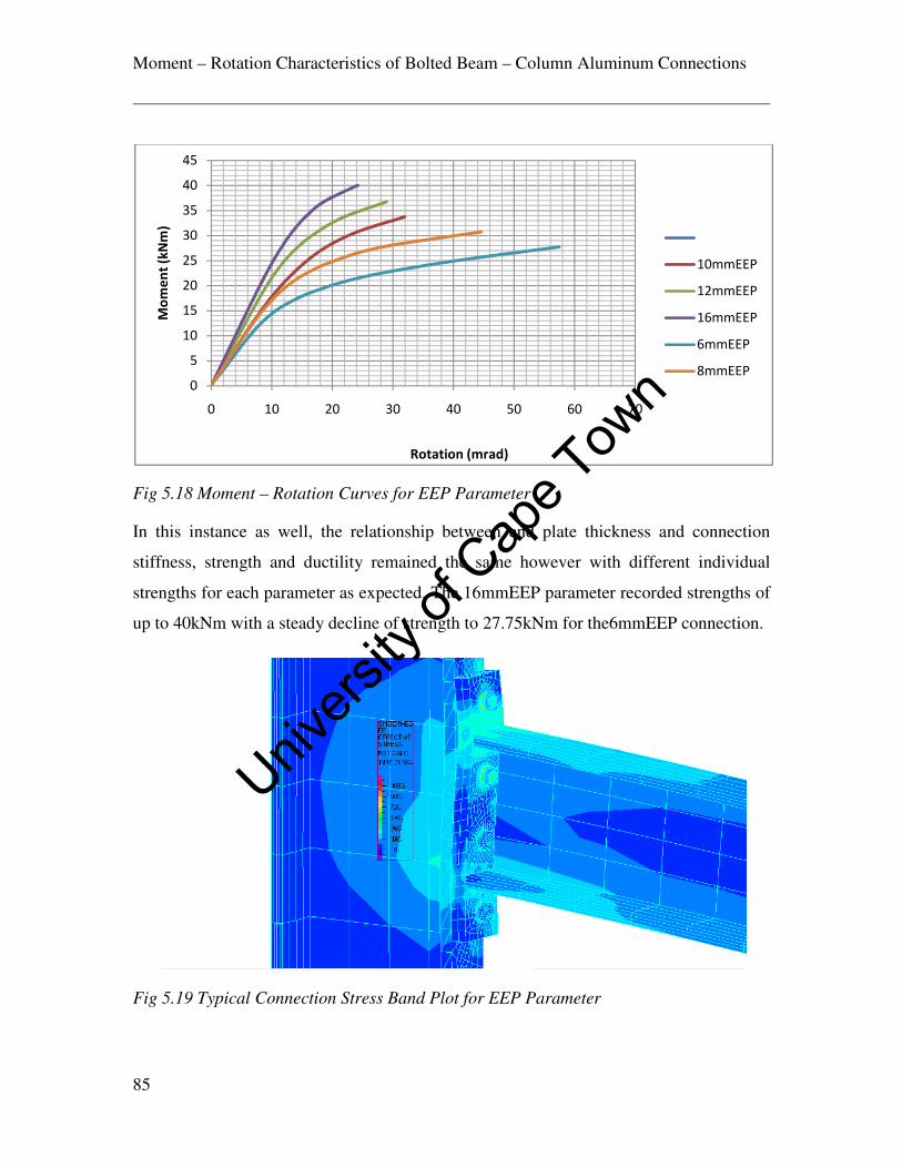
Moment – Rotation Characteristics of Bolted Beam – Column Aluminum Connections
85
Fig 5.18 Moment – Rotation Curves for EEP Parameter
In this instance as well, the relationship between end plate thickness and connection
stiffness, strength and ductility remained the same however with different individual
strengths for each parameter as expected. The 16mmEEP parameter recorded strengths of
up to 40kNm with a steady decline of strength to 27.75kNm for the6mmEEP connection.
Fig 5.19 Typical Connection Stress Band Plot for EEP Parameter
0
5
10
15
20
25
30
35
40
45
0 10 20 30 40 50 60 70
Mo
me
nt
(kN
m)
Rotation (mrad)
10mmEEP
12mmEEP
16mmEEP
6mmEEP
8mmEEP
Univers
ity of
Cap
e Tow
n
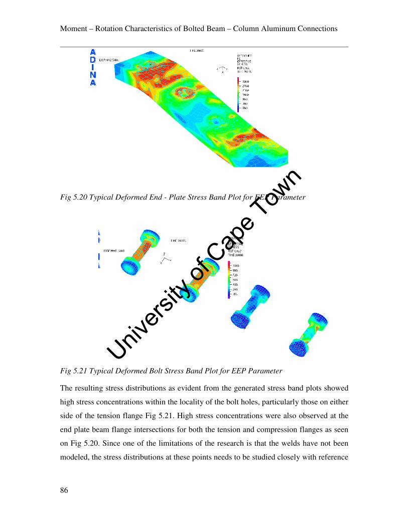
Moment – Rotation Characteristics of Bolted Beam – Column Aluminum Connections
86
Fig 5.20 Typical Deformed End - Plate Stress Band Plot for EEP Parameter
Fig 5.21 Typical Deformed Bolt Stress Band Plot for EEP Parameter
The resulting stress distributions as evident from the generated stress band plots showed
high stress concentrations within the locality of the bolt holes, particularly those on either
side of the tension flange Fig 5.21. High stress concentrations were also observed at the
end plate beam flange intersections for both the tension and compression flanges as seen
on Fig 5.20. Since one of the limitations of the research is that the welds have not been
modeled, the stress distributions at these points needs to be studied closely with reference
Univers
ity of
Cap
e Tow
n

Moment – Rotation Characteristics of Bolted Beam – Column Aluminum Connections
87
to the effects of the HAZ and consequent loss of strength at the welds. The bolts closer to
the tension flange of the beam demonstrated high tensile stresses as expected Fig 5.21.
Univers
ity of
Cap
e Tow
n

Moment – Rotation Characteristics of Bolted Beam – Column Aluminum Connections
88
CHAPTER 6
DISCUSSION OF RESULTS
6.1 The Effect of Geometry on Connection Behavior.
The load deflection curves of the various parameters as outlined in chapter 5 is plotted for
each end plate thickness as seen on Figs 6.1 – 6.5. The effect of the geometry of the
connections can be seen on each of these plots for the different thicknesses of end plates.
There is not much difference between the EP and the EPSW plots from the diagrams.
This is expected as the moment of area of the column member is substantially larger than
that of the beams thus providing it with a superior stiffness. However, the stresses
generated on the column webs for the stiffened members are substantially lower.
Fig 6.1 Load Deflection Curves For 6mm End Plates
0
5
10
15
20
25
30
0 50 100 150 200 250
Loa
d
Defection
6mmEEP
6mmEP
6mmEPSW
6mmEPAB
Univers
ity of
Cap
e Tow
n

Moment – Rotation Characteristics of Bolted Beam – Column Aluminum Connections
89
Fig 6.2 Load Deflection Curves For 8mm End Plates
The EEP connections demonstrate higher initial stiffness and strength as compared to the
EP, EPSW and EPAB connections. This matches results obtained by earlier research
work on steel end plate connections {14}. EP and EPSW connections demonstrate much
lower initial stiffness’s and strengths whilst EPAB connections are characterized by very
low strengths due to premature bolt failure.
Fig 6.3 Load Deflection Curves For 10mm End Plates
0
5
10
15
20
25
30
35
0 20 40 60 80 100 120
Loa
d
Deflection
8mmEEP
8mmEP
8mmEPSW
8mmEPAB
0
5
10
15
20
25
30
35
40
0 20 40 60 80 100 120
Loa
d
deflection
10mmEEP
10mmEP
10mmEPSW
10mmEPABUniv
ersity
of C
ape T
own

Moment – Rotation Characteristics of Bolted Beam – Column Aluminum Connections
90
Fig 6.4 Load Deflection Curves For 12mm End Plates
Fig 6.5 Load Deflection Curves For 16mm End Plates
It can clearly be seen that the there is a direct relationship between connection strength,
stiffness and ductility as documented by previous research on similarly connected steel
end plate connections {14}{23}{25}. Connections with thicker end plates such as the
16mmEP showed much higher strength as characterized by the ultimate moments
attained prior to failure. It however exhibited much reduced ductility compared to the
thinner end plates 6mmEP. The relationship between initial stiffness and end plate
thickness can also be seen by the slope of the moment - rotation curve at the origin of the
plots as shown on Figs 5.4, 5.8, 5.13 and 5.18. The plots were derived from data
0
5
10
15
20
25
30
35
40
0 20 40 60 80 100
Loa
d
Deflection
12mmEEP
12mmEP
12mmEPSW
12mmEPAB
0
5
10
15
20
25
30
35
40
45
0 10 20 30 40 50 60 70
Loa
d
Deflection
16mmEEP
16mmEP
16mmEPSW
16mmEPAB
Univers
ity of
Cap
e Tow
n
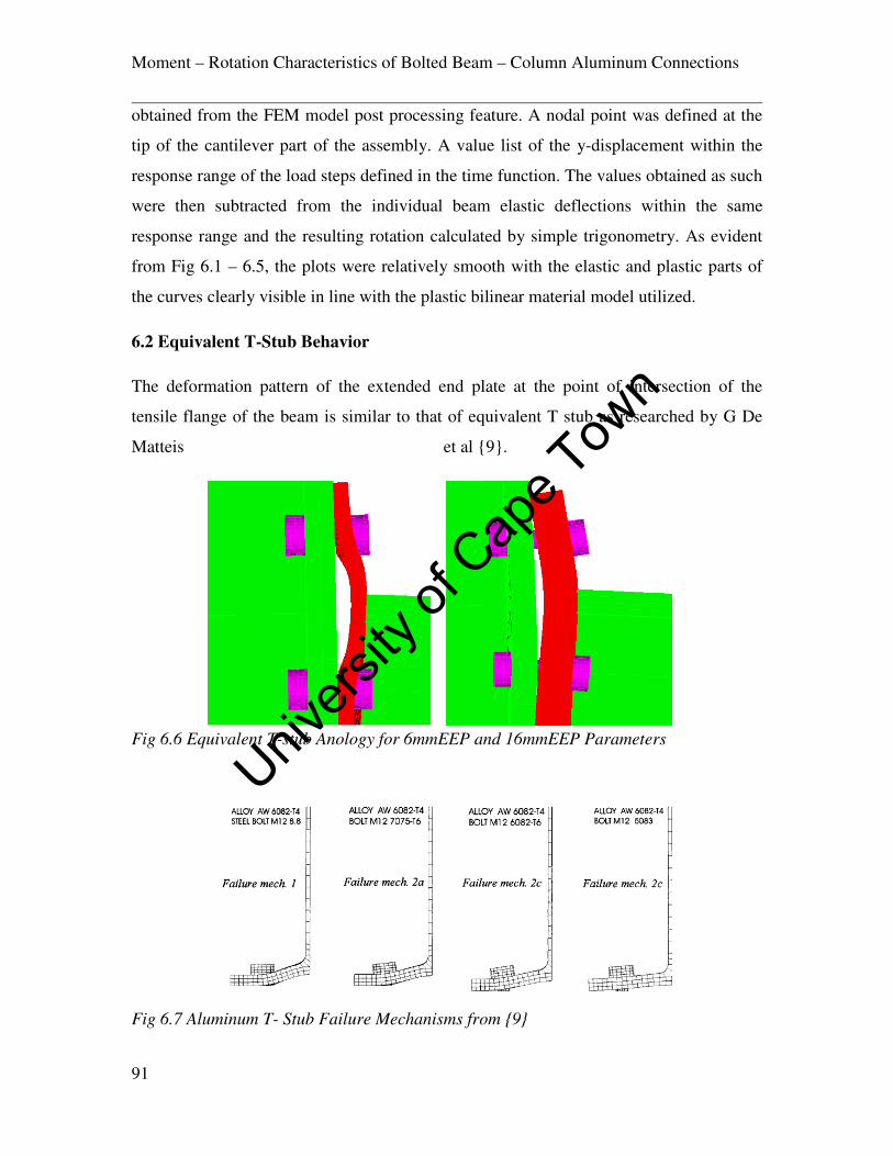
Moment – Rotation Characteristics of Bolted Beam – Column Aluminum Connections
91
obtained from the FEM model post processing feature. A nodal point was defined at the
tip of the cantilever part of the assembly. A value list of the y-displacement within the
response range of the load steps defined in the time function. The values obtained as such
were then subtracted from the individual beam elastic deflections within the same
response range and the resulting rotation calculated by simple trigonometry. As evident
from Fig 6.1 – 6.5, the plots were relatively smooth with the elastic and plastic parts of
the curves clearly visible in line with the plastic bilinear material model utilized.
6.2 Equivalent T-Stub Behavior
The deformation pattern of the extended end plate at the point of intersection of the
tensile flange of the beam is similar to that of equivalent T stub as researched by G De
Matteis et al {9}.
Fig 6.6 Equivalent T-stub Anology for 6mmEEP and 16mmEEP Parameters
Fig 6.7 Aluminum T- Stub Failure Mechanisms from {9}
Univers
ity of
Cap
e Tow
n
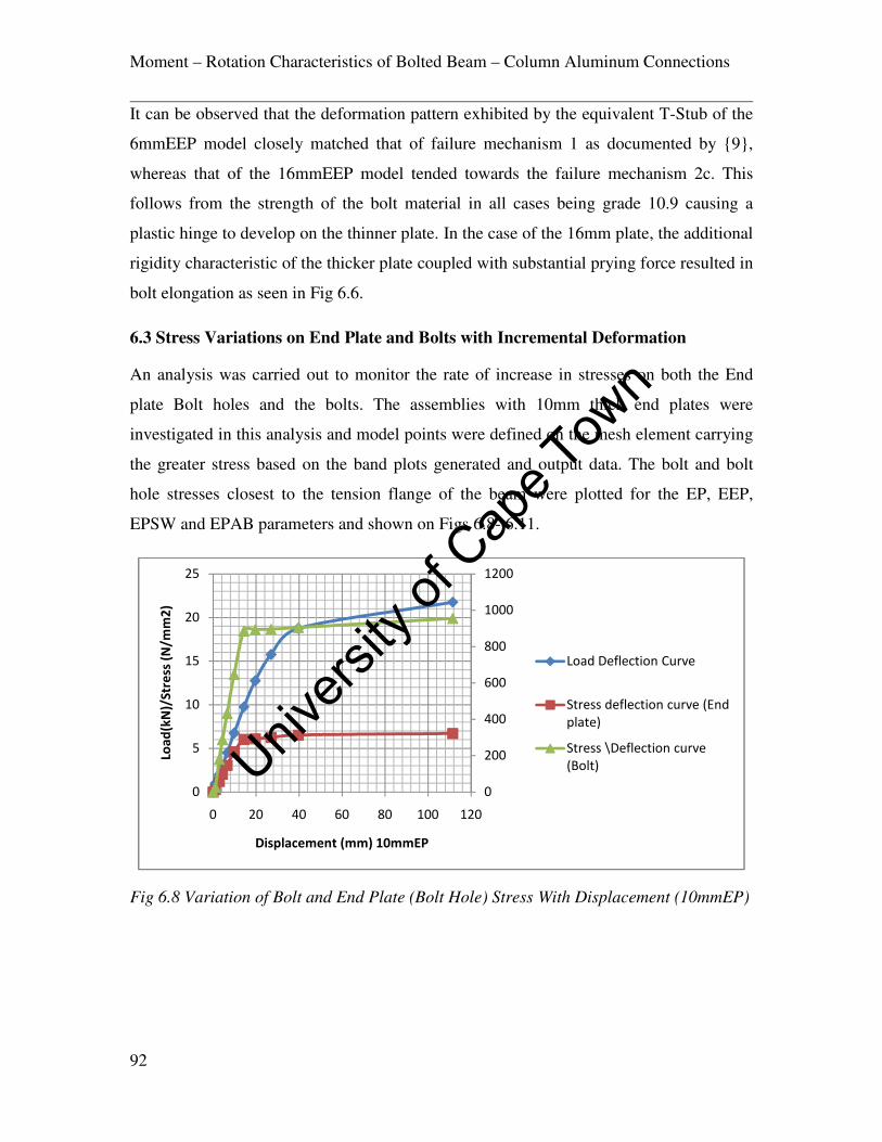
Moment – Rotation Characteristics of Bolted Beam – Column Aluminum Connections
92
It can be observed that the deformation pattern exhibited by the equivalent T-Stub of the
6mmEEP model closely matched that of failure mechanism 1 as documented by {9},
whereas that of the 16mmEEP model tended towards the failure mechanism 2c. This
follows from the strength of the bolt material in all cases being grade 10.9 causing a
plastic hinge to develop on the thinner plate. In the case of the 16mm plate, the additional
rigidity characteristic of the thicker plate coupled with substantial prying force resulted in
bolt elongation as seen in Fig 6.6.
6.3 Stress Variations on End Plate and Bolts with Incremental Deformation
An analysis was carried out to monitor the rate of increase in stresses on both the End
plate Bolt holes and the bolts. The assemblies with 10mm thick end plates were
investigated in this analysis and model points were defined on the mesh element carrying
the greater stress based on the band plots generated and output data. The bolt and bolt
hole stresses closest to the tension flange of the beam were plotted for the EP, EEP,
EPSW and EPAB parameters and shown on Figs 6.8- 6.11.
Fig 6.8 Variation of Bolt and End Plate (Bolt Hole) Stress With Displacement (10mmEP)
0
200
400
600
800
1000
1200
0
5
10
15
20
25
0 20 40 60 80 100 120
Loa
d(k
N)/
Str
ess
(N
/mm
2)
Displacement (mm) 10mmEP
Load Deflection Curve
Stress deflection curve (End
plate)
Stress \Deflection curve
(Bolt)Univers
ity of
Cap
e Tow
n

Moment – Rotation Characteristics of Bolted Beam – Column Aluminum Connections
93
Fig 6.9 Variation of Bolt and End Plate (Bolt Hole) Stress With Displacement
(10mmEEP)
Fig 6.10 Variation of Bolt and End Plate (Bolt Hole) Stress With Displacement
(10mmEPSW)
-200
0
200
400
600
800
1000
0
5
10
15
20
25
30
35
40
0 10 20 30 40 50
Loa
d(k
N)/
Str
ess
(N/m
m2
)
deflection (mm) 10mmEEP
Load deflection curve
stress deflection curve
(Plate)
Stress deflection curve (
bolt)
-200
0
200
400
600
800
1000
1200
0
5
10
15
20
25
0 20 40 60 80
Loa
d(k
N)/
Str
ess
(N/m
m2
)
deflection (mm) 10mmEPSW
load deflection curve
stress deflection curve
(plate)
stress deflection curve
(bolt)Univers
ity of
Cap
e Tow
n

Moment – Rotation Characteristics of Bolted Beam – Column Aluminum Connections
94
Fig 6.11 Variation of Bolt and End Plate (Bolt Hole) Stress With Displacement
(10mmEPAB)
The stress increase in the bolts appears to be much steeper in the EP and SW assemblies
as compared to that of the EEP connection. This can be seen from the Fig 6.12 where bolt
stress is plotted with deflection. At a deflection of 8mm, stresses in the bolt are in the
region of 600MPa whereas for the EEP connection, it takes a deflection of the order of
18mm for 600MPa stress to be generated. In the case of the stress on the end plate bolt
holes, the reverse seems to occur as stress are generated much faster in the EEP assembly
than in the other two parameters. This could be explained by the presence of an additional
row of bolt above the tension flange which actually relieves some of the stress on the
bolts immediately below the tension flange. Being that the moment resistance of the joint
is generated by couples with the centre of rotation at the compression flange or at the
bottom edge of the end plate as the case may be, additional moment capacity is generated
by this extra row of bolts which creates a connection with a much larger initial stiffness.
The additional bolt row above the tension flange, which can be idealized as an equivalent
t-stub, acts to share the tensile force being generated by this flange.
0
1
2
3
4
5
6
7
8
9
-50
0
50
100
150
200
250
300
350
400
0 10 20 30
Loa
d (
kN
)/S
tre
ss (
N/m
m2
)
Displacement (mm)10mmEPAB
stress deflection curve(end
Plate)
Stress deflection curve
(bolt)
load deflection curve
Univers
ity of
Cap
e Tow
n

Moment – Rotation Characteristics of Bolted Beam – Column Aluminum Connections
95
Fig 6.12 Variation of Bolt Stress With Displacement All Parameters (10mm) End Plates
Fig 6.13 Variation of Bolt Hole Stress on End Plate, All Parameters (10mm) End Plates
6.4 Stress Variations on End Plate / Tension Flange Joint
The fabrication of end plate connections primarily involves the welding of the beam
element to the designed thickness of end plate, at the edge to be assembled with the
column, in beam to column connections. The welding procedure which leads to reduced
-200
0
200
400
600
800
1000
1200
0 20 40 60 80 100 120
Str
ess
(N
/mm
2
Displacement (mm) Bolt stress variation
10mmEP
10mmEEP
10mmSW
10mmEPAB
0
50
100
150
200
250
300
350
400
0 20 40 60 80 100 120
Str
ess
(N
/mm
2)
Displacement (mm) End Plate Bolt Hole Stress Variation
10mmEP
10mmEEP
10mmEPSW
10mmEPAB
Univers
ity of
Cap
e Tow
n

Moment – Rotation Characteristics of Bolted Beam – Column Aluminum Connections
96
material strength in areas of close proximity to the weld (HAZ), and indeed the weld
itself is worthy of investigation as it is oftentimes a source of connection failure in end
plate connections. Eurocode 9 specifies a heat softening factor ρ 7¡ as 0.65 for 6xxx
series aluminum alloys, supplied as extrusions, sheet and plate in the T6 condition for
MIG welding, and as 0.5 for TIG welding. Thus characteristic strengths will have to be
multiplied by these factors for the actual post welded strength to be obtained. Although
the welds and the effects of the heat affected zone (HAZ) were not considered in the
modeling process due to the already elaborate bolt modeling process, their effects in areas
of high stress which are potential weld locations in fabrication procedures can be
evaluated by monitoring the stress levels as the loading process is carried out through the
time step feature. As such, the elements connecting the tension flange and the end plate
were monitored for stress increments with load and these were recorded for further
analysis. Data for the EEP parameter in this respect is seen on Table 6.1. Considering
ultimate limit state, the percentage loss of strength at the HAZ for MIG will render the
ultimate tensile strength of the alloy (6082 T6) to be reduced from 330MPa to about
214.5MPa. It can be seen as expected that end plate thickness plays an important role in
the rate of stress development in the assemblies. There is a marked decrease in the
strengths of the connections if the HAZ on the tension flange is to be taken into account.
Although the 16mm End plate (16mmEEP) records strengths of up to 40kNm, it could
well be the case that if connections of this nature were fabricated and tested, the
predominant failure mode will be tensile cracks on the tension flange within close
proximity of the weld induced HAZ. Most of the connections recorded 0.65Fy at about
30% of their strengths based on the ADINA results.
Univers
ity of
Cap
e Tow
n

Moment – Rotation Characteristics of Bolted Beam – Column Aluminum Connections
97
P (kN) HAZ Stress (MPa)
6mmEEP 8mmEEP 10mmEEP 12mmEEP 16mmEEP
0 0 0 0 0 0
1 19.75 17.02 21.06 19.74 18.05
2 56.37 38.53 49.31 44.6 38.39
3 85.09 58.12 74.06 67.25 57.73
4.5 127.7 87.16 111.25 100.87 86.6
6.75 187.75 130.82 167.09 151.31 129.89
9.75 239.76 196.53 234.45 204.27 185.57
12.75 259.61 241.63 262.95 243.98 219.96
15.75 278.85 262.14 284.19 263.43 251.11
18.75 292.87 273.47 294.29 272.73 263.82
21.75 309.3 279.67 298.58 283.37 270.9
24.75 319.15 289.43 303.04 295.65 278.38
27.75 326.87 303.42 307.62 301.64 288.36
30.75 316.92 313.2 306.63 294.71
33.75 318.07 311.17 301.53
36.75 316.01 307.85
39.75 313.59
40 314.11
Table 6.1 Stress Increase in T-Stub of EEP parameters
Fig 6.14 Stress Increase in T-Stub of EEP Parameters
0
50
100
150
200
250
300
350
0 10 20 30 40 50
Te
nsi
on
Fla
ng
e H
AZ
Str
ess
(M
pa
)
Load (kN)/ Moment (kNm)
6mmEEP
8mmEEP
10mmEEP
12mmEEP
16mmEEP
0.65Fy
Fy
Univers
ity of
Cap
e Tow
n

Moment – Rotation Characteristics of Bolted Beam – Column Aluminum Connections
98
CHAPTER 7
CONCLUSIONS AND RECOMMENDATIONS
7.1 Introduction
End plate connections prove to be useful in structural design due to their relative ease of
fabrication and erection in practical circumstances. They are mainly utilized where there
is a desire for high strength and stiffness to be attained. The design of aluminum end
plate connections with enough moment capacity to match that of the connected member
proves to be much more delicate than in the case of steel for reasons based on the
material properties. Reduced flexural rigidity due to lower young’s modulus / renders
aluminum beams and frames to be more susceptible to higher deformations under
loading. Although the behavior of simple connections is not covered in this work, it is
expected that huge demands will not be placed on these connection types as in moment
connections due to the fact that they transmit minimal moments in beam to column
connections and are mainly characterized by the shear capacity of the attached bolts and
bolt hole bearing. Thus the demands on moment connections prove to be greater and
require much scrutiny for optimized designs to be achieved capable of satisfying
structural requirements.
7.2 Conclusions
The ability of the utilized FEM package ADINA to reproduce moment rotation
relationships of beam-column end plate connections based on existing data used in
chapter 4 from (Coelho A, M, and Bijlaard, F, 2006) {14} provides substantial
confidence going forward in this research area given that the data collected in this work
was done with relatively sophisticated equipment compared to that of similar work done
much earlier. Although the effects of the heat affected zone HAZ was not considered, the
data from stress plots obtained from the models were able to predict possible failures due
to HAZ related material inconsistencies on the tension flange of the connected beams.
This is particularly useful as endplate connections in reality are a combination of bolted
and welded assemblies. As such both of these aspects of the design must be taken into
consideration.
Univers
ity of
Cap
e Tow
n

Moment – Rotation Characteristics of Bolted Beam – Column Aluminum Connections
99
The classification as shown in Table 7.1 shows all connections of the EP, EPSW and
EPAB in the semi rigid category with regards to the stiffness category. Only the
connections with aluminum bolts EPAB fell under the nominally pinned classification
with regards to strength. This can be attributed to the untimely bolt failure in these
connections with the bolt stresses reaching the yield strength {\of the alloy 6082 T6 quite
early in the loading process. Only the 12mmEEP and the 16mmEEP parameters attained
the rigid criterion for stiffness classification, but were not able to develop full strength
characterized by the plastic moment of the beam, <�. The effects of the HAZ monitored
for the EEP parameter by extracting stress increments close to the tension flange weld
suggests that strength may be curtailed to as little as 30% of the recorded values due to
weld failure or tension flange cracking close to the HAZ. Thus the welding process
remains the most delicate feature in the fabrication of such connections and the quality
will largely determine the capacity to attain the design strength.
7.3 Classification of Connections
The behavior of connections as stated earlier is critical in the analysis of structural
systems. Connection failure is oftentimes the cause of loss of structural integrity in a
system and as such its importance cannot be overemphasized, and are typically classified
by their ability to restore the stiffness, strength and ductility of the connected structural
elements. This phenomenon is the framework upon which the various classification
systems are based {1}{2}{16}. The connections analyzed using the Finite Element
software ADINA have provided data obtained by the moment rotation characteristics
through which they can be classified using any of the classification systems that have
been proposed. The connections will now be classified comparatively using the Eurocode
3 system with a 3m beam length as a reference.
Univers
ity of
Cap
e Tow
n

Moment – Rotation Characteristics of Bolted Beam – Column Aluminum Connections
100
Table 7.1 Connection Classification According To Eurocode 3
Connection Initial stiffness ¢£,¤¥¤ (kNm/rad)
Moment
Resistance ¦£,§¨ (kNm)
Stiffness
Classification
Strength
Classification
6mmEEP 2092 28 semi-rigid partial strength
8mmEEP 2192 31 semi-rigid partial strength
10mmEEP 2202 34 semi-rigid partial strength
12mmEEP 2436 37 rigid partial strength
16mmEEP 2621 39 rigid partial strength
Connection Initial stiffness ¢£,¤¥¤ (kNm/rad)
Moment
Resistance ¦£,§¨ (kNm)
Stiffness
Classification
Strength
Classification
6mmEP 830 16 semi-rigid partial strength
8mmEP 895 19 semi-rigid partial strength
10mmEP 946 21 semi-rigid partial strength
12mmEP 1157 25 semi-rigid partial strength
16mmEP 1610 30 semi-rigid partial strength
Connection Initial stiffness ¢£,¤¥¤ (kNm/rad)
Moment
Resistance ¦£,§¨ (kNm)
Stiffness
Classification
Strength
Classification
6mmEPAB 682 7.2 semi-rigid Nominally pinned
8mmEPAB 765 7.6 semi-rigid Nominally pinned
10mmEPAB 757 8.4 semi-rigid Nominally pinned
12mmEPAB 869 8.7 semi-rigid Nominally pinned
16mmEPAB 1741 10 semi-rigid Nominally pinned
Connection Initial stiffness ¢£,¤¥¤ (kNm/rad)
Moment
Resistance ¦£,§¨ (kNm)
Stiffness
Classification
Strength
Classification
6mmEPSW 847 16 semi-rigid partial strength
8mmEPSW 1046 19 semi-rigid partial strength
10mmEPSW 1126 22 semi-rigid partial strength
12mmEPSW 1272 25 semi-rigid partial strength
16mmEPSW 1600 28 semi-rigid partial strength
Univers
ity of
Cap
e Tow
n
Moment – Rotation Characteristics of Bolted Beam – Column Aluminum Connections
101
7.4 Recommendations
The behavior of 6082 T6 aluminum bolts in these connections renders them un suitable in
withstanding the substantial stresses developed, and as such the required strength and
stiffness’s characteristic of moment connections will be difficult to attain with their use
particularly with column web stiffeners. The capacity of the class two 6082 T6 elements
to withstand local buckling particularly in the compression flange is further clarified as
all connections were restricted to end plate buckling and bolt failure modes. Particular
attention must be paid to welding procedures of end plates to limit loss of mechanical
properties. End plates thinner than the thickness of the column flange are characterized
by less favorable strengths and as such could prove to be unsuitable if high connection
strength is desired.
7.5 Future Research
The authenticity of the information obtained in this work can be further corroborated by
the implementation of experimental work based on assembly geometry utilized. The area
of aluminum connections remains relatively sparse in terms of research material. As such,
there are endless possibilities and connection assemblies based on various aluminum
sections of other classes available in the market to investigate. These results could
provide an insight for designers to achieve optimum performance of aluminum
connections based on relationships between geometry and connection stiffness, strength
and ductility. The behavior of other classes of beam and column elements are worthy of
investigation to document their performance. Simple connections in beam – column
aluminum joints are also potential research areas as these have received little attention to
date and as such could prove worthwhile.
Univers
ity of
Cap
e Tow
n

Moment – Rotation Characteristics of Bolted Beam – Column Aluminum Connections
102
REFERENCES
1. Bjorhovde, R., Brozetti, J., Colson, A., 1990.A Classification System for Beam to
Column Connections. Journal of Structural Engineering, 116(11):3059-3076
2. Nethercot, D.A, Li, T.Q, Ahmed, B, 1998. Unified Classification System for Beam-
Column Connections. Journal of Constructional Steel Research, 45(1): 39-65
3. SCI, BCSA. 2002. Joints in Steel Construction, Simple Connections. P212
4. Jaspart, J.P., Demonceau, J.F., 2008.European Design Recommendations for Simple
joints in Steel Structures. Journal of Constructional Steel Research,64 822-832
5. BS 5950:Structural Use of Steelwork in Buildings; Part 1 1990
6. SCI, BCSA. 1995. Joints in Steel Construction, Moment Connections. P207/95
7. Swanson J, A, Leon RT. Bolted Steel Connections; Test on T- Stub Components. Journal
of Structural Engineering ASCE 2000: 126(1): 50 – 6
8. Popov E. P, Shakhzod M, Takhirov. 2002. Bolted Large Seismic Steel Beam – Column
Connections Part 1. Engineering Structures, 24 (2002) 1523- 1534
9. De Matteis, G, Mandara, A, Mazzolani, F, M., 2000. T Stub Aluminum Joints: Influence
of Behavioral Parameters. Computers and Structures, 78 (2000) 311-327
10. Lazzarin, P, Milani, V, Quaresimin, M.1997. Scatter Bands Summarizing the Fatigue
Strength of Aluminum Alloy bolted Joints. International Journal of Fatigue, Vol. 19.No.
5 pp. 401-407
11. UNI 8634-85.”Strutture di leghe di alluminio. Istruzioni per il calcolo e la ascuzione”( in
Italian), Milano, Italy 1985
12. Minguez, J, M Vogell, J. 2006.Effect of Toque Tightening on the Fatigue Strength of
Bolted Joints. Engineering Failure Analysis, 13 (2006) 1410-1421
13. Mazzolani F. M., Aluminum Alloy Structures. Chapman & Hall, London 1995
14. Coelho A, M, Bijlaard, F. Experimental Behavior of High Strength Steel End-Plate
Connections. Journal of Constructional Steel Research. 63 (2007) 1228-1240
15. Eurocode 9, Part 1-1, Design of Aluminum Structures 1999
16. Eurocode 3, Design of Steel Structures. Part 1-8, Design of Joints 1993
17. Malan S.F. Paterson A.E. “Aluminum Design Guide 1” South Africa : AFSA, 1989
18. De Matteis G., Mazzolani F.M, Panico S. “Experimental Tests On Pure Aluminum Shear
Panels With Welded Stiffeners” Elsevier 2008
Univers
ity of
Cap
e Tow
n
Moment – Rotation Characteristics of Bolted Beam – Column Aluminum Connections
103
19. Aluminum Design Manual. Aluminum Association, Washington, DC, 8th Ed, January
2005
20. Menzemer, C.Ortiz, Morgado, R. Srivatsan, T.S. An investigation Into the Bearing
Strength of Three Aluminum Alloys, Material Science and Engineering, A327(2002) 203
– 212
21. Wald F, Sokol Z, Moal M, Mazura V, Muzeau J.P., “Stiffness of Cover Plates With
Slotted Holes”. Journal of Constructional Steel Research. 60 (2004) 621 – 634
22. Kulak G.L, Fisher J.W, and Struik J. “Guide to Design Criteria for Bolted and Riveted
Joints”.2nd
Ed., John Wiley & Sons, Inc., New York.(1987)
23 Krishnamurthy N. “A Fresh Look at Bolted End- Plate behavior and Design”
Engineering Journal American institute of steel Construction, 15(2), 39-49.(1978)
24 American Institute of Steel Construction. “Allowable Stress Design Manual of
Steel Construction” Chicago Ill. (1989)
25 Zoetemeijer P. A design Method for the Tension zone of Statically Loaded
Bolted Beam to Column connections. Heron 1974; 20(1); 1-59.
26 Menzemer C.C,Fei L,Srivatsan T.S.”Mechanical Response and Failure of Bolted
Connection Elements in Aluminum Alloy 5083” Journal of Material Engineering and
Performance (1998)
27 May J.E, Menzemer C.C. “Strength of Bolted Aluminum Tension Members”
Journal of Structural Engineering (2005)
28 http://aluminium-offshore.com/our-business/helideck-support-frames
29 http://www.tfhrc.gov/pubrds/spring97/alum.htm
30 ADINA R&D Inc. “ADINA Theory and Modeling Guide”, MA 024725, USA
(2008)
Univers
ity of
Cap
e Tow
n