
Moisture Modeling Moisture Models - University of Waterloo · Moisture Models zMust understand ......
11
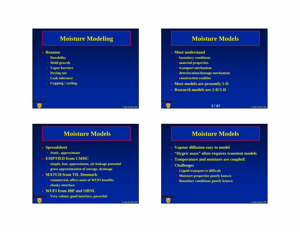
© John Straube 2005 Moisture Modeling Moisture Modeling Reasons • Durability • Mold growth • Vapor barriers • Drying out • Leak tolerance • Cupping / curling © John Straube 2005 Moisture Models Moisture Models Must understand • boundary conditions • material properties • transport mechanism • deterioration/damage mechanism • construction realities Most models are presently 1-D Research models are 2-D/3-D 2 / 87 © John Straube 2005 Moisture Models Moisture Models Spreadsheet • Static, approximate EMPTIED from CMHC • simple, fast, approximate, air leakage potential • gross approximation of storage, drainage MATCH from TIL Denmark • commercial, offers most of WUFI benefits • clunky interface WUFI from IBP and ORNL • Very robust, good interface, powerful © John Straube 2005 Moisture Models Moisture Models Vapour diffusion easy to model “Hygric mass” often requires transient models Temperature and moisture are coupled! Challenges • Liquid transport is difficult • Moisture properties poorly known • Boundary conditions poorly known
Transcript of Moisture Modeling Moisture Models - University of Waterloo · Moisture Models zMust understand ......
© John Straube 2005
Moisture ModelingMoisture Modeling
Reasons• Durability• Mold growth• Vapor barriers• Drying out• Leak tolerance• Cupping / curling
© John Straube 2005
Moisture ModelsMoisture Models
Must understand • boundary conditions• material properties• transport mechanism• deterioration/damage mechanism• construction realities
Most models are presently 1-DResearch models are 2-D/3-D
2 / 87
© John Straube 2005
Moisture ModelsMoisture Models
Spreadsheet• Static, approximate
EMPTIED from CMHC• simple, fast, approximate, air leakage potential• gross approximation of storage, drainage
MATCH from TIL Denmark• commercial, offers most of WUFI benefits• clunky interface
WUFI from IBP and ORNL• Very robust, good interface, powerful
© John Straube 2005
Moisture ModelsMoisture Models
Vapour diffusion easy to model“Hygric mass” often requires transient modelsTemperature and moisture are coupled!Challenges• Liquid transport is difficult• Moisture properties poorly known• Boundary conditions poorly known
© John Straube 2005
ResultsResults
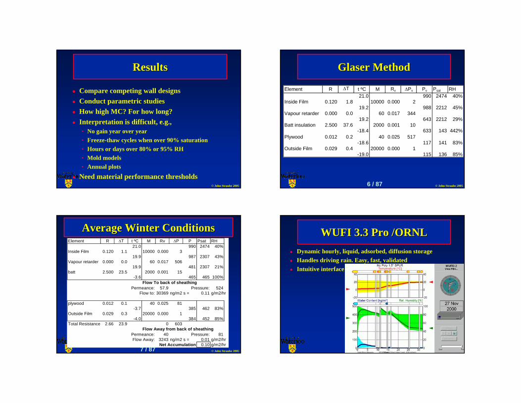
Compare competing wall designsConduct parametric studiesHow high MC? For how long?Interpretation is difficult, e.g.,• No gain year over year• Freeze-thaw cycles when over 90% saturation• Hours or days over 80% or 95% RH• Mold models• Annual plots
Need material performance thresholds© John Straube 2005
Glaser MethodGlaser Method
Element R ∆T t ºC M Rv ∆Pv Pv Psat RH21.0 990 2474 40%
Inside Film 0.120 1.8 10000 0.000 219.2 988 2212 45%
Vapour retarder 0.000 0.0 60 0.017 344 19.2 643 2212 29%
Batt insulation 2.500 37.6 2000 0.001 10 -18.4 633 143 442%
Plywood 0.012 0.2 40 0.025 517 -18.6 117 141 83%
Outside Film 0.029 0.4 20000 0.000 1 -19.0 115 136 85%
6 / 87
© John Straube 2005
Element R ∆T t ºC M Rv ∆P P Psat RH21.0 990 2474 40%
Inside Film 0.120 1.1 10000 0.000 319.9 987 2307 43%
Vapour retarder 0.000 0.0 60 0.017 506 19.9 481 2307 21%
batt 2.500 23.5 2000 0.001 15 -3.6 465 465 100%
Flow To back of sheathingPermeance: 57.9 Pressure: 524
Flow to: 30369 ng/m2 s = 0.11 g/m2/hr
plywood 0.012 0.1 40 0.025 81 -3.7 385 462 83%
Outside Film 0.029 0.3 20000 0.000 1 -4.0 384 452 85%
Total Resistance 2.66 23.9 0 603Flow Away from back of sheathing
Permeance: 40 Pressure: 81Flow Away: 3243 ng/m2 s = 0.01 g/m2/hr
Net Accumulation 0.10 g/m2/hr
Average Winter ConditionsAverage Winter Conditions
7 / 87 © John Straube 2005
WUFI 3.3 Pro /ORNLWUFI 3.3 Pro /ORNLDynamic hourly, liquid, adsorbed, diffusion storageHandles driving rain. Easy, fast, validatedIntuitive interface
© John Straube 2005 © John Straube 2005
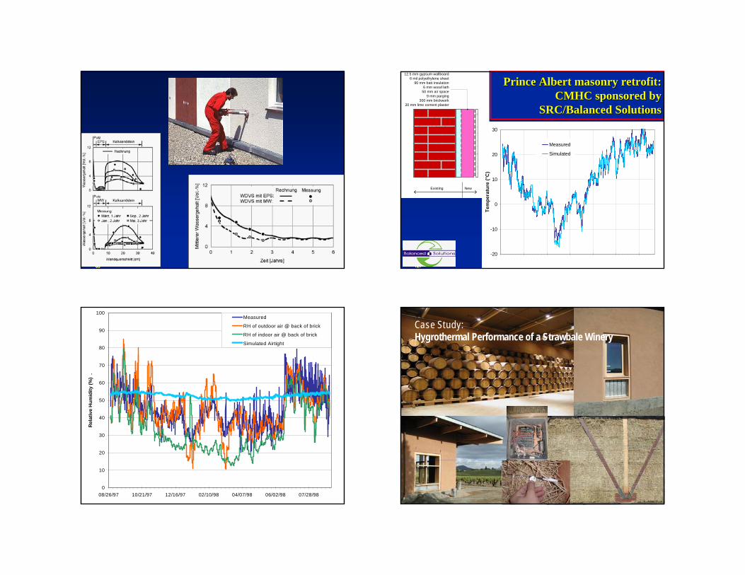
Prince Albert masonry retrofit: Prince Albert masonry retrofit: CMHC sponsored by CMHC sponsored by
SRC/Balanced SolutionsSRC/Balanced Solutions
Existing New
12.5 mm gypsum wallboard6 mil polyethylene sheet
90 mm batt insulation6 mm wood lath
50 mm air space9 mm parging
300 mm brickwork20 mm lime cement plaster
-20
-10
0
10
20
30
08/26/97 10/21/97 12/16/97 02/10/98 04/07/98 06/02/98 07/28/98
Tem
pera
ture
(°C
)
Measured
Simulated
© John Straube 2005
Prince Albert masonry retrofitPrince Albert masonry retrofit
0
10
20
30
40
50
60
70
80
90
100
08/26/97 10/21/97 12/16/97 02/10/98 04/07/98 06/02/98 07/28/98
Rel
ativ
e H
umid
ity (%
) .
Measured
RH of outdoor air @ back of brick
RH of indoor air @ back of brick
Simulated Airtight
© John Straube 2005
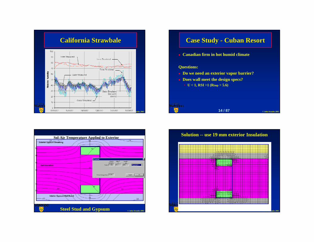
California California StrawbaleStrawbaleCase Study: Hygrothermal Performance of a Strawbale Winery
© John Straube 2005
California California StrawbaleStrawbale
© John Straube 2005
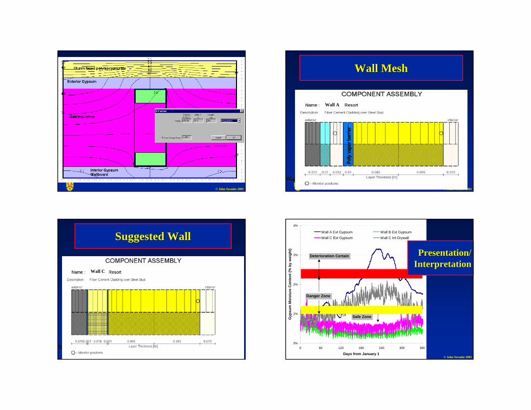
Case Study Case Study -- Cuban ResortCuban Resort
Canadian firm in hot humid climate
Questions:Do we need an exterior vapor barrier?Does wall meet the design specs?• U < 1, RSI >1 (Rimp > 5.6)
14 / 87
© John Straube 2005Steel Stud and Gypsum
Sol-Air Temperature Applied to Exterior
© John Straube 2005
Solution -- use 19 mm exterior Insulation
© John Straube 2005 © John Straube 2005
Wall MeshWall Mesh
Wall A
Poly
vapo
r bar
rier
© John Straube 2005
Suggested WallSuggested Wall
Wall C
© John Straube 2005
0%
1%
2%
3%
4%
0 60 120 180 240 300 360
Days from January 1
Gyp
sum
Moi
stur
e C
onte
nt (%
by
wei
ght)
Wall A Ext Gypsum Wall B Ext GypsumWall C Ext Gypsum Wall C Int Drywall
Deterioration Certain
Danger Zone
Safe Zone
Presentation/Presentation/InterpretationInterpretation
© John Straube 2005
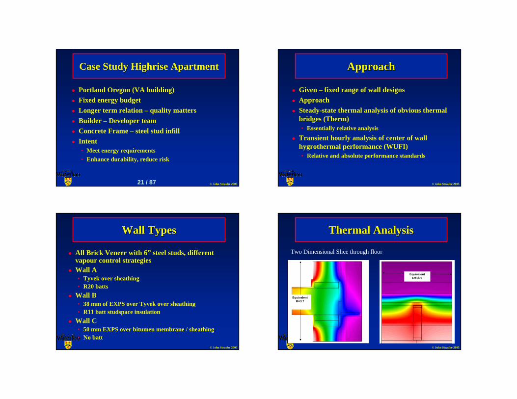
Case Study Case Study HighriseHighrise ApartmentApartment
Portland Oregon (VA building)Fixed energy budgetLonger term relation – quality mattersBuilder – Developer teamConcrete Frame – steel stud infillIntent• Meet energy requirements• Enhance durability, reduce risk
21 / 87 © John Straube 2005
ApproachApproach
Given – fixed range of wall designsApproachSteady-state thermal analysis of obvious thermal bridges (Therm)• Essentially relative analysis
Transient hourly analysis of center of wall hygrothermal performance (WUFI)• Relative and absolute performance standards
© John Straube 2005
Wall TypesWall Types
All Brick Veneer with 6” steel studs, different vapour control strategiesWall A• Tyvek over sheathing• R20 batts
Wall B• 38 mm of EXPS over Tyvek over sheathing• R11 batt studspace insulation
Wall C• 50 mm EXPS over bitumen membrane / sheathing• No batt
© John Straube 2005
Thermal AnalysisThermal Analysis
Two Dimensional Slice through floor
EquivalentR=3.7
Equivalent R=14.9
© John Straube 2005
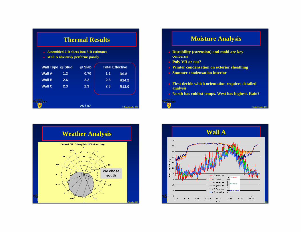
Thermal ResultsThermal Results
Assembled 2-D slices into 3-D estimatesWall A obviously performs poorly
Wall Type @ Stud @ Slab Total Effective
Wall A 1.3 0.70 1.2
Wall B 2.6 2.2 2.5
Wall C 2.3 2.3 2.3
R6.8
R14.2
R13.0
25 / 87 © John Straube 2005
Moisture AnalysisMoisture Analysis
Durability (corrosion) and mold are key concernsPoly VR or not?Winter condensation on exterior sheathingSummer condensation interior
First decide which orientation requires detailed analysisNorth has coldest temps. West has highest. Rain?
© John Straube 2005
Weather AnalysisWeather Analysis
We chose south
© John Straube 2005
Wall AWall A
© John Straube 2005
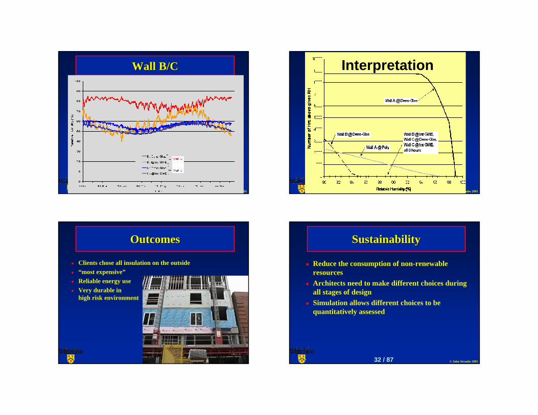
Wall B/CWall B/C
© John Straube 2005
Interpretation
© John Straube 2005
OutcomesOutcomes
Clients chose all insulation on the outside“most expensive”Reliable energy useVery durable in high risk environment
© John Straube 2005
SustainabilitySustainability
Reduce the consumption of non-renewable resourcesArchitects need to make different choices during all stages of designSimulation allows different choices to be quantitatively assessed
32 / 87
© John Straube 2005
Energy ModelsEnergy Models
Whole building energy analysis• Peak – equipment sizing• Hourly – system choice, annual consumption, comfort
Use is growing but rareModels tend to be too complex• Easy to make big errors
Simple hourly needed
© John Straube 2005
Energy ConsumptionEnergy Consumption
Requires time to develop sophisticated modelsGood, if cumbersome, models available• DOE 2.1E (soon to be replaced)• TRNSYS (modular component)• Energy-10• EE-4• Quest• HOTCAN (soon ESP-r)
34 / 87
© John Straube 2005
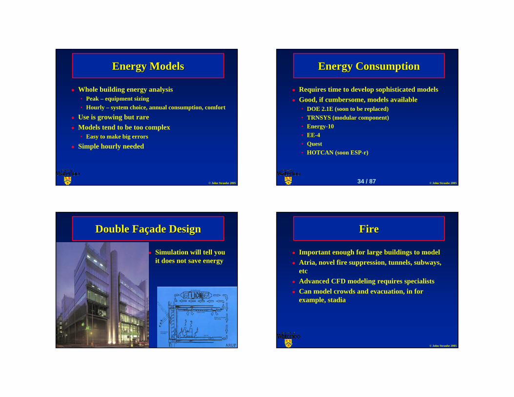
Double FaDouble Faççade Designade Design
Simulation will tell you it does not save energy
© John Straube 2005
FireFire
Important enough for large buildings to modelAtria, novel fire suppression, tunnels, subways, etcAdvanced CFD modeling requires specialistsCan model crowds and evacuation, in for example, stadia
© John Straube 2005
FireFire
Source: RWDI © John Straube 2005
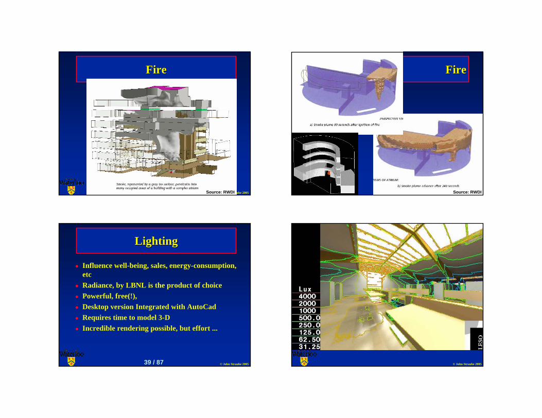
FireFire
Source: RWDI
© John Straube 2005
LightingLighting
Influence well-being, sales, energy-consumption, etcRadiance, by LBNL is the product of choicePowerful, free(!), Desktop version Integrated with AutoCadRequires time to model 3-DIncredible rendering possible, but effort ...
39 / 87 © John Straube 2005
© John Straube 2005
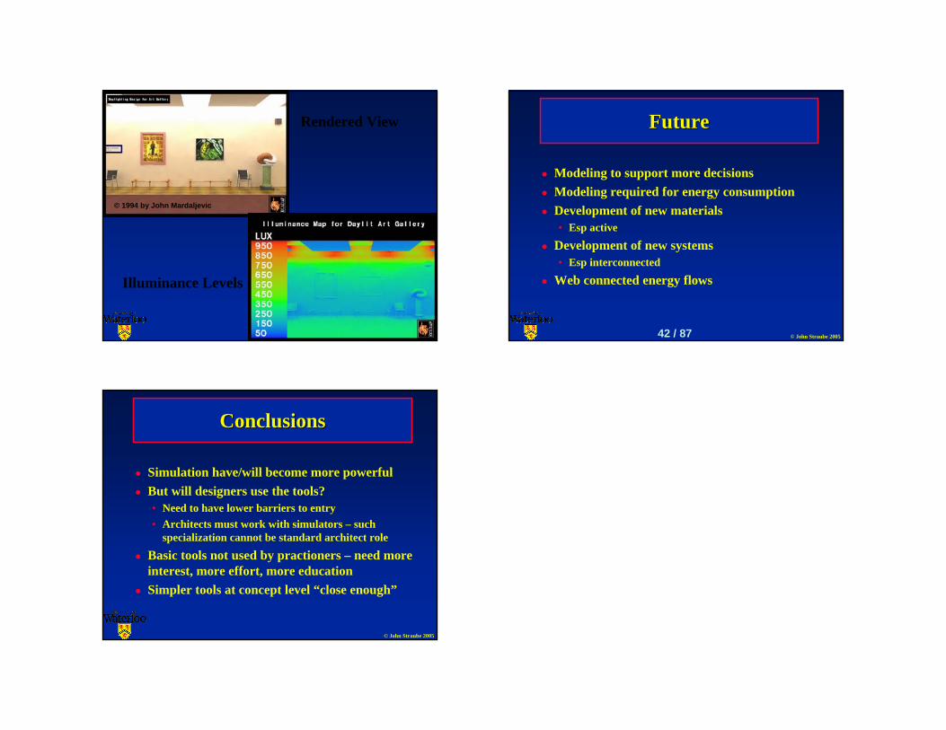
© 1994 by John Mardaljevic
Rendered View
Illuminance Levels
© John Straube 2005
FutureFuture
Modeling to support more decisionsModeling required for energy consumptionDevelopment of new materials• Esp active
Development of new systems• Esp interconnected
Web connected energy flows
42 / 87
© John Straube 2005
ConclusionsConclusions
Simulation have/will become more powerfulBut will designers use the tools?• Need to have lower barriers to entry• Architects must work with simulators – such
specialization cannot be standard architect role
Basic tools not used by practioners – need more interest, more effort, more educationSimpler tools at concept level “close enough”


