MOHSEN JAHANMIRI - Chalmerswebfiles.ita.chalmers.se/~chernora/files/... · MOHSEN JAHANMIRI...
51
Research report 2011:01 Boundary Layer Transitional Flow in Gas Turbines MOHSEN JAHANMIRI Division of Fluid Dynamics Department of Applied Mechanics CHALMERS UNIVERSITY OF TECHNOLOGY Göteborg, Sweden, 2011
Transcript of MOHSEN JAHANMIRI - Chalmerswebfiles.ita.chalmers.se/~chernora/files/... · MOHSEN JAHANMIRI...
Research report 2011:01
Boundary Layer Transitional Flow in Gas Turbines
MO H S EN J A H A N MIR I
Division of Fluid Dynamics
Department of Applied Mechanics
CHALMERS UNIVERSITY OF TECHNOLOGY
Göteborg, Sweden, 2011

2
Boundary Layer Transitional Flow in Gas Turbines
M O H S E N J A H A N M I R I
© M O H S E N J A H A N M I R I , 2011
Research report 2011:01
ISSN 1652-8549
Division of Fluid Dynamics
Department of Applied Mechanics
CHALMERS UNIVERSITY OF TECHNOLOGY
SE-412 96 Göteborg
Sverige
Telephone +46 (0)31 772 1000

3
Boundary Layer Transitional Flow in Gas Turbines
Mohsen jahanmiri
Dept. of Applied Mechanics, Chalmers University of Technology Göteborg, Sweden
& Dept. of Mech. and Aerospace Engineering, Shiraz University of Technology
Shiraz, Iran
Abstract The distinguishing features of transition in turbomachinery flows are that they are unsteady on time scales longer than typical eddy turnover times, occur in harsh and highly disturbed environments at awkward Reynolds numbers, and are generally three-dimensional (even in the mean). As a consequence, the flow is a veritable-fluid-dynamical ‘zoo’, characterized by separation, reattachment, transition, relaminarization , retransition, etc., all often occurring in the same flow. But how important is transition research for the turbomachinery industry? GE compressor tests (made by Halstead) showing transition extending over 60% of the blade chord, and estimates of potential improvement inefficiency by several percentage points; considering how widely turbomachines are used in energy conversion and propulsion systems, significant economic and environmental benefits are possible. It is found out that the ‘lack of ability to predict the location of boundary layer transition for components in gas turbine engines is impeding our ability to gain maximum benefit from our design effort. If a complete computational fluid dynamics (CFD) design tool incorporating transition were to be available, it is foreseen airfoil designs with higher blade loading that would reduce part count and improve efficiency. It is estimated that a 1% improvement in the efficiency of a low pressure turbine would result in a saving of $52,000 per year on a typical airliner. Improved transition technology was thus very relevant. So keeping in mind such important issue like transition phenomena in design and operation of gas turbines, it is the aim of this review paper to elucidate the recent research activities in this area.
Introduction Though numerous gas turbines have been used worldwide for over half a century, the flow on the turbine blades is not yet completely understood and consequently difficult to predict. In a first approximation, the heat transfer depends on the boundary layer state. Its calculation is one of the main objectives of a turbine designer. Precise calculation is needed to achieve high efficiency engines. If it is now possible to compute laminar or turbulent boundary layers with good accuracy (except in particular cases such as strong separation), transition is always difficult to compute as it is the birth of turbulence. All the calculation methods which are able to take transition into account, use modelling or correlations deduced from experiments performed sometimes several years before. In these experiments, the definitions of the onset and end criteria of the transition are often given in different ways. This is more than just the question of the quality of the measurements, it is one of the reasons for the scattering of the different results. A second reason is related to the many factors influencing the transition process: pressure gradients, Reynolds number, curvature, level and scale of turbulence, roughness, unstationarity, etc., which they sometimes act together and it is then difficult to separate the governing effects (Bario and Beral, 1998). In the literature, many papers concern the measurements on turbine blades. Mostly, they present global measurements and only a few give detailed measurements useful for turbulence or heat transfer modelling. This is related to the fact that it is very difficult to obtain sufficiently thick boundary layers for detailed measurements on the suction and pressure side of a turbine blade. Most of the detailed results are obtained on flat plate with a pressure gradient imposed by the external wall (Blair, (1982), Keller and Wang (1994), and Kestoras and Simons (1993) for negative pressure gradients) or on the concave wall for Görtler vortex studies (Peerhosseini and Wesfreid (1988). Sharma et al. (1982) present results for the suction side of a turbine cascade. Studies of Van Treuren et al.

4
(2002) shows the results of measurements of suction surface of blade in a turbine cascade flow under ultra Low Reynolds number conditions. Nevertheless, laminar-turbulent transition in boundary layers influences performance of many technical devices. The location of the onset and the extension of transition are of major importance since they determine drag and lift forces and heat fluxes that are crucial for overall efficiency and performance of a variety of machinery and devices. Among the most common examples of the machinery, where the laminar-turbulent transition is of particular importance, are gas and aero-engine turbines. Despite technical maturity of gas turbines, the research optimization and development concerning this technology still continues, as increasing the engine’s performance by a fraction of percent or improving the turbine cooling in face of ever-increasing turbine inlet temperature provides enormous economic benefits. Hence, once more it is emphasized, the understanding of the laminar-turbulent transition in gas turbine cascades plays a very important role in their optimization (Mayle, 1991). It is necessary to mention that the flow in the turbomachinery stage is essentially turbulent and unsteady, where the non-stationary flow character results from the mutual rotor-stator blade row interactions. Periodic phenomena generated by blade row interactions excite the flow in both the blade passage and boundary layers on the blade surfaces, and they trigger an increased turbulent spot production and finally shift the location of laminar-turbulent transition upstream. This laminar-turbulent transition mechanism is known as ”wake-induced transition” (Mayle, 1991). Despite numerous experimental and numerical investigations, the physics of the unsteady phenomena in turbomachinery flows is not well understood. The understanding of this phenomenon is important in order to incorporate new modelling methods in CFD codes, which will be used in future by turbomachinery designers. In fact, despite a lot of effort directed to improve the modelling strategy, the transition modelling still largely limits the quality of the CFD codes today, and indeed the errors in estimation of the onset and extension of the transition can affect the calculated machine efficiency by several percent and the component life by more than an order of magnitude (Elsner, 2007). The importance of transitional flow in turbomachinery could be better indicated by giving an example. Figure 1 (Narasimha, 1985) , based on a study reported by Turner (1971), shows the heat transfer coefficient on the two sides of an internally cooled turbine blade, at different freestream turbulence levels. Note that there are extensive regions of favourable pressure gradient on both surfaces. The peak heat transfer rate, which occurs on the convex surface, is appreciably higher than would be expected if the flow were turbulent from the leading edge, as can be seen by comparison with the results calculated by the methods of Spalding and Patankar (1967). It is now well known that such peaks (which have long been known in surface skin friction coefficient as well, see, e.g. Coles, 1954), are associated with transition, and tend to occur towards the end of the transition zone. Note also how the onset of transition is unaffected by turbulence level up to 2.2 %, but has moved rapidly forward at 5.9 %. On the concave surface, on the other hand, the effects are not so clear-cut, but at the highest turbulence levels transition appears to occur early. These observations show how heat transfer rates are strongly influenced by complex interactions between free-stream disturbances, surface pressure distribution and curvature and transition location on a turbine blade. Very few reviews exist on transitional flow in gas-turbines in the literature (e.g. Mayle, 1991), and the relevant information on this topic are majorly scattered and not compiled properly. So the main aim of this report is to highlight major research works accomplished so far in both experimental and computational studies. The following will be the major parts of this review, first the transition prediction and its modeling will be discussed and next different types of transition modes in gas turbine are examined. Transition process in various gas-turbine components is the third major issue which is elaborated, and finally the effect different parameters on transitional flow in general and specifically in turbomachinery are explained.

5
Figure 1: Heat transfer rate on a turbine blade (based on Turner, 1971~ Top, blade section. Middle, external velocity distribution on blade surface. Bottom, local heat transfer coefficient (in units of CHU/ft2 h °C: multiply by 1.753 to convert to W/m2 K) along chord at different free-stream turbulence levels q, at an exit Mach number of 0.75. Note that at q = 5.9, about 80% of the convex surface of the blade is in the transition zone.
Transition prediction In axial-flow turbomachinery, the design trend is toward increasing airfoil loading in an effort to reduce weight and cost of future systems. Transition prediction is critical for accurate loss predictions of high lift airfoils, and the full multi-moded (Mayle (1991)) nature of the transition process must be considered. Lakshminarayana(1991), Simoneau and Simon (1993), Simon and Ashpis (1996), Dunn (2001), and Yaras (2002) all provide detailed reviews of the state of the art in predictive techniques for turbomachinery, and they point to the need for improved models for transition. Elevated levels of free stream turbulence (“Tu”>1.0%) have a significant effect on pre-transitional, or “quasi-laminar (QL)” boundary layers. Further, there is an opinion that the quality of the laminar boundary layer at transition onset must be predicted accurately before transition modelling can be used most effectively. Therefore, it is important to capture accurately the field-wise development of free stream turbulence quantities. To that end, the ability of the k-ω turbulence model of Wilcox (1998) to predict the development of “Tu” was validated against the experimental data of Ames (1994). Additionally, an accurate technique for modeling the effects of “Tu” on laminar boundary layers within the framework of the k-ω model was developed. In testing against cascade data it was found that open-literature models for attached and separated-flow transition (see Figure 2) were not sufficiently accurate for implementation in a design system. Consequently, an effort was launched to develop new correlations for attached- and separated-flow transition. A dimensional analysis was performed considering all transition-relevant quantities available within the framework of a Reynolds

6
Averaged Navier-Stokes(RANS) simulation performed with a two-equation turbulence model. A database of the resulting dimensionless groups was constructed from open-literature and Pratt & Whitney in-house cascade data (Praisner and Clark, 2007). The cascade data were supplemented with quantities based on the aforementioned modeling techniques for free stream turbulence development and its effects on laminar boundary layers. An investigation of the resulting database enabled the development of new models for attached- and separated-flow transition.
Figure 2: Schematic representation of suction-side, laminar-separation characteristics showing both reattached (a) and stalled (b) conditions. Transition onset is generally the outcome of competition between different instability modes. Laminar instability theory describes "natural" transition under low free stream turbulence. The
basis of this was originally confirmed by Schubauer and Klebanoff (1955), and led to the en prediction method for transition onset (van Ingen (1956), Smith and Gamberoni (1956)). A shortcut method for implementing this technique, in which the envelopes of the maximum disturbance amplification ratio are approximated by empirical relations involving integral boundary layer parameters, was later suggested by Gleyzes et al. (1985). Early methods for predicting transition onset necessarily employed integral boundary layer calculations, due to the rudimentary computation facilities then available. Here, calculation of the laminar layer momentum thickness Reynolds number proceeds from the origin until some previously determined correlation curve for transition commencement is intersected. Crabtree (1958) reviewed available data for turbulent breakdown under low free stream turbulence conditions, and prediction methods proposed by other workers up to that time. He also considered the desirability of allowing for history effects on disturbance amplification over the region of unstable laminar flow. Crabtree finally opted for a simplified criterion provided by a curve of momentum thickness Reynolds number against the local value of Pohlhausen pressure gradient parameter at breakdown under low free-stream turbulence conditions. He concluded by foreshadowing that a family of similar curves might be required for higher free-stream turbulence conditions."Bypass" transition under high free-stream turbulence is a concept originally introduced by Morkovin (1969) but never precisely defined. It was erroneously presumed by some workers to imply instantaneous turbulent breakdown with zero length of transitional flow. However this was not the intention: bypass transition does not necessarily exclude instability processes, which are, in fact, essential for transition: only the long region of two dimensional wave amplification preceding the appearance of three-dimensional disturbances (spanwise periodicity)in low turbulence flow is bypassed. The approach adopted to bypass transition prediction has built on that of Crabtree [5]. Abu-Ghannam and Shaw (1980) observed transition inception on a flat plate over a range of pressure gradients and free-stream turbulence conditions; they further considered the effects of flow history, but were unable to find any simple relation and presented their transition onset criteria for different turbulence
7
levels in the same form as Crabtree, based purely on local conditions at breakdown. Mayle (1991) followed a similar approach, but used the acceleration parameter favoured in turbine engineering practice as the pressure gradient parameter: there is no difference in principle, as the latter quantity is a function of both the Pohlhausen pressure gradient parameter and the momentum thickness Reynolds number. Mayle noted that the effects of pressure gradient on transition onset were significantly reduced under the high turbulence levels experienced in a turbomachine; he therefore suggested using the flat plate result, in which the momentum thickness Reynolds number at breakdown was a simple function of the freestream turbulence level, for predicting transition onset on turbomachine blades. The method and location of free-stream turbulence measurements is an important issue. Due to the strong accelerations and decelerations experienced in turbomachine blade cascades, the local value of free-stream turbulence at the location of boundary layer transition onset may differ greatly from that at entry to a blade row. Currently used transition onset correlations involve data from several workers, who may have adopted different bases for defining free-stream turbulence values: Abu-Ghannam and Shaw, for example, use neither a local value at breakdown, nor some mean value over the region of unstable flow, but rather an average value of free-stream turbulence taken midway between the leading edge of their plate and the location in question. The latter point of detail may not be appreciated by many users of their results. Any blade surface boundary layer must eventually separate if subjected to a strong enough deceleration. Laminar separation bubbles can result from laminar separation followed by sufficiently early transition in the separated shear layer and subsequent turbulent reattachment. Errors in predicting the length of these bubbles has often led to the failure of aerofoil design routines to give stable or accurate solutions. Early attempts at describing separation bubble development and bursting, (Horton, (1969), Roberts (1980)) were based on semi-empirical models assuming a constant pressure over the separated laminar shear layer region, instantaneous transition, and a linear variation of free-stream velocity during turbulent reattachment. An integral boundary layer computation procedure was used, and the transition onset location was predicted using correlations for the length of the separated laminar shear layer in terms of the momentum thickness Reynolds number at separation. The implication here is that separated flow transition represents an entirely different process from that in attached flow. This approach may be fairly reliable for leading edge separation bubbles, but has fundamental problems with the calculation of mid-chord bubbles. The transition onset correlations do not admit the possibility of the bubble length varying continuously to zero as the Reynolds number and/or free-stream turbulence level are increased. This is physically unreasonable, and can lead to bubbles appearing and disappearing in consecutive cycles of iterative calculations with viscous/inviscid interaction procedures. The
en method of transition onset prediction does not suffer from this problem, and has been employed in the later viscous/inviscid interaction methods (Gleyzes et al. (1985), Youngren and Drela (1991)) it also makes an inherent allowance for history effects by using local values for amplification rate throughout the instability region to compute the amplification factor n. The MISES code (Youngren and Drela (1991)) is widely used in the turbomachinery industry for the preliminary design of blade elements in cascade. The viscous layer computation procedure is adapted from the earlier work of Drela & Giles (1987) for predicting isolated aerofoil
performance. Modifications of the en transition onset prediction procedure to allow for elevated free-stream turbulence effects, via the method of Mack (1977), are discussed by Drela (1998). The latter publication discusses further modifications adopted in MISES to ensure physically reasonable behavior and computational stability. It also provides a useful comparison of transition onset predictions from the en and Abu-Ghannam & Shaw correlations after first recasting the AG&S correlation by using the shear layer shape factor, instead of the Pohlhausen parameter, as a pressure gradient parameter. This device is necessary to ensure that transition prediction does not fail in a separation bubble, where the pressure gradient falls to zero downstream of separation in the real flow. Drela’s modified en transition onset prediction method is also applicable to separated laminar shear layers. Thus the MISES code provides a

8
unified approach to predicting transition onset from the three principal mechanisms(natural, bypass and separated flow transition)that avoids discontinuities introduced by employing different correlations for individual modes. This doubtless contributes to the very creditable performance of the MISES code in capturing both leading edge and mid-chord separation bubbles on compressor and turbine blades. Laminar boundary layers on turbomachine blades only survive until they separate or suffer turbulent breakdown. The viscous instability of a laminar boundary layer was originally investigated by Tollmien. Under low free-stream turbulence conditions instability is initiated when two-dimensional unstable Tollmien-Schlichting (TS) waves are formed; these propagate in the streamwise direction at less than 40% stream velocity. They subsequently develop three-dimensionality and spanwise variations, and a concentration into peaks, valleys and hairpin vortices then occurs. Turbulent spots are formed in the peak regions of vorticity, and eventually coalesce to form continuously turbulent flow. Emmons (1951) was the first to propose a turbulent spot model of transitional flow. Schubauer & Klebanoff (1955) later observed the growth of an artificial turbulent spot generated on a flat plate without an imposed pressure gradient. Walker & Gostelow (2009), have been working on more accurate transition length predictions, based on measurements of transition length under adverse pressure gradients in natural and by-pass transition (Gostelow et al. (1994)), and of triggered turbulent spots. It was realized that spot characteristics for adverse pressure gradients could be quite different from those for zero or favourable pressure gradients. The characteristics of turbulent spots under adverse pressure gradients were previously unknown. Measurements were undertaken of triggered spots under a range of adverse pressure gradients. Under an adverse pressure gradient a spot is formed at the centre of a highly amplified transverse wave packet; it convects at a lower velocity than under a zero pressure gradient. The adverse pressure gradient spot spreads at an included angle as high as sixty degrees, compared with about twenty degrees under zero pressure gradient and even lower under favourable pressure gradients. It has been demonstrated (Gostelow et al. (1996)) that a triggered spot replicates the development of natural transition; but the behavior of such a spot additionally seems to represent well the response of the blade boundary layer to an imposed wake disturbance. Following a turbulent spot is an extensive relaxation trail or "calmed region". The calmed region is effective in delaying the harmonic breakdown to turbulence and in resisting laminar separation [Gostelow et al. (1997)). The effect of the calmed region in delaying natural transition after a spot passage is clear: turbulence eventually contaminates the calmed region, but only after the calmed region has had a considerable favourable influence on the downstream flow. Judicious use of this property has resulted in a substantial reduction in the blade count of low pressure (LP) turbines in modern aircraft engines (Hodson and Howell (2005)). More recent work has extended the spot-spreading correlations (Gostelow et al. (1996)) well into the laminar separation region (D’Ovidio et al. (2001a), and (2001b)). To reliably predict bubble length, however, it is necessary to gain a better understanding of the dynamics of transition in a separated shear layer and of the differing closure modes of bubbles. This is likely to involve an appreciation of instabilities in the separated shear layer rather than of the TS wave to turbulent spot and by-pass transition routes which have proved useful for attached flows. Kelvin-Helmholtz (KH) instability dominates the separated shear layer at low freestream turbulence levels, but the breakdown mechanism is significantly altered under elevated freestream turbulence, as described by McAuliffe & Yaras (2007).
Transition modelling The variety of possible transition mechanisms in turbomachinery flows makes it difficult to propose the general strategy for numerical simulation. Intuitively, the best solution for the modelling of the transitional boundary layer is the application of Direct Eddy Simulation (DES) or Large Eddy Simulation (LES). However, in LES, which unlike DNS resolves only dynamically important (large) scales, the effect of unresolved small scales is modeled (Elsner, 2007). One question that arises when applying LES to the transition problem regards its capability to

9
predict the development of the shear layer and vortices with scales, which are close to the numerical filter (Huai et al., 1997). A subgrid scale model should not dissipate the energy of low level perturbations during the initial stages of transition, but should reproduce the energy transfer to the unresolved scales during non-linear stages when these marginally resolved structures are generated. LES was already successfully used in simulating the bypass transition on a flat plate, among the others by Voke and Yang (1995) and Huai et al. (1997)who were able to show the pre -transitional linear instability modes, the secondary instability Λ-vortex structures and the streaky like structures. However, the application of LES for the modelling of the transition is still limited to the low Reynolds number flows as for higher Reynolds numbers the difference between the largest and the smallest eddies increases, and a progressively wider range of scales needs to be resolved by the subgrid scale model. The second limitation is the required numerical mesh and resulting high computational time, because when approaching the wall, the scales diminish their dimension so that finer and finer grid is required. Hence the RANS methods and, for unsteady calculations URANS, with the appropriately modelled transitional boundary layer remain the only presently applicable engineering tool to study the transitional flows. It means that it is worth to make effort to improve and look for new RANS or URANS modeling approaches, especially because of strong interest from the industry. Application of the existing low-Re turbulence models for the laminar-turbulent transition boundary layer, as reviewed by Savill (2002) and Menter et al. (2002), is a highly empirical procedure which requires experimental data for proper calibration. It means that no model generates a reliable result for various combinations of Reynolds numbers, free stream turbulences and pressure gradients. Additionally, the results are sensitive to initial conditions, boundary conditions and grid resolution. In these methods, usually various experimental correlations are used to determine the onset of transition. According to Menter et al. (2002), the ability of a low-Reynolds turbulence model to predict the transition seems to be coincidental, as the calibration of the damping functions is based on the viscous sub-layer behaviour and not on the transition from laminar to turbulent flow. The transition process could be described by the intermittency parameter γ , which gives information about the fraction of time when the flow is turbulent. That is why the coupling with intermittency seems to be the best way to take into account the physical mechanism of transitional flow and to model the transition in a proper way. One of the most classic methods for the modelling of the transition with applications of the intermittency parameter is a model formulated by Dhawan and Narasimha (1958). The estimated intermittency factor at the current location and in time (for unsteady calculations)is usually used as a multiplier of the production term in the turbulence model. In the pre-transitional regime, γ is set to zero, and when it attains the positive value, the transition is initiated. Recently, some new methods have been developed, and all of them rely on the intermittency parameter. The first one is the Prescribed Unsteady Intermittency Model (PUIM) developed at Cambridge University (Vilmin et al., 2003), which solely relies on empirical correlations. PUIM calculates a distance-time intermittency distribution as a function of space and time fields(constant in time in the case of steady flow simulation). To have this information, PUIM employs the Mayle (1991) and Abu-Ghannam and Shaw (1980)correlations for the transition onset and also the Mayle (1991) or Gostelow et al. (1996) correlations for the spot production rate. The spreading of turbulent spots is prescribed using functions of the edge velocity and the pressure gradient parameter. For a separated flow, the other Mayle correlation gives the spot production rate from the momentum-thickness Reynolds number at separation. The detection of the separation arises from the skin friction and Thwaites criterion. Such a solution ensures that not only attached flow transition onsets but also separated onsets could be identified. The high quality of this approach was confirmed among the others in T106A (Vilmin et al., 2003)and on N3-60 test cases (Elsner et al., 2004). A more general description of the intermittency is obtained from the dynamic intermittency convection-diffusion-source equation, where the first method was developed by Lodefier and Dick (2006) at Ghent University, and the second is a result of the work performed by Menter and co-authors (2004). According to the first approach, named L&D hereafter, two dynamic equations for the intermittency: one for the near-wall intermittency γ and one for the

10
free-stream-intermittency ζ were proposed. The near wall intermittency takes into account the fraction of time during which the near-wall velocity fluctuations caused by transition have a turbulent character and tend to zero in the free stream region, while on the wall it attains unity. The free-stream factor ζ describes the intermittent behaviour of turbulent eddies coming from the free stream and impacting into the underlying pseudo-laminar boundary layer. Near the wall, the eddies are damped and the free-stream factor goes to zero while in the free-stream it reaches unity. For the onset detection in the case of bypass and turbulence wake induced transition, the model employs the Mayle (1991) correlation. For a quasi-steady separation transition, a criterion proposed for such a type of flows by Mayle (1991) is applied. An additional criterion is used in the case of wake induced transition over a separation bubble. This method shows to be an efficient tool for prediction of wake interaction with the separation bubble and especially for the wake interaction with the attached flow (Lodefier et al., 2005).A different strategy is proposed by Menter et al. (2004). In this method, only local information is used to activate the production term in the intermittency equation, and the link between the correlations and the intermittency equation is achieved through the use of the vorticity Reynolds number. The proposed model is based on the SST turbulence model and two transport equations. The first one is the intermittency equation used to trigger the transition process. The second transport equation of the momentum thickness Reynolds number Reθt is implemented for avoiding non-local operations introduced by experimental correlations. Outside the boundary layer the transport variable is forced to follow the value of Reθt given by the correlations. For this purpose, the standard and in-house correlations are used for the natural, bypass and separation induced transition. This input is then diffused into the boundary layer with the use of the standard diffusion term. Due to this methodology, strong variation of the turbulence intensity and pressure gradient, which are typical for turbomachinery, can be taken into account. The local information used to trigger the onset of the transition in this model is the
vorticity Reynolds number Rev. This quantity depends only on density, viscosity, wall distance and vorticity, so it could be easily computed at each grid point. It is the main advantage of this methodology which could be applied for parallel calculations on unstructured grids. The study carried out by Piotrowski and Elsner (2006) shows that this model, despite the lack of physics in the proposed additional equation for Reθt, is able to properly predict the periodical evolution of the boundary layer under the influence of impinging wake with adequatequality. Recently, the Intermittency Transport Model (ITM), which was derived on the basis of Menters’ approach discussed above, has been proposed by Piotrowski and Elsner (2006). Encouraging results for the N3-60 turbine profile both for steady and unsteady inflow conditions have been obtained (see Figure 3). One should notice however, that some tuning of the correlation for length of the transition should be done. All the above transition models are used in connection with the linear turbulence model. Another approach is proposed by Lardeau and Leschziner (2004), where the intermittency based formulation is coupled with the low-Realgebraic Reynolds-stress model. From this assumption, it results that this model should return properly all the Reynolds-stress components, which is especially important for the near wall flows where strong turbulence anisotropy is present. The advantage of this modelling approach is the ability to model the pre-transitional rise of turbulence intensity, which was experimentally confirmed, among the others by Elsner et al. (2004). This ability is achieved mainly due to the introduction of parameters modifying damping functions which control its cross-flow and streamwise variations by taking into account the Klebanoff mode properties observed in the pre-transitional phase of boundary layer development. The experimental verification of this methodology based mainly on ERCOFTAC data (www://ercoftac.mech.surrey.ac.uk) shows improvement in the prediction of onset transition and its length (Lardeau and Leshziner, 2004). They also obtained reasonably good results for the unsteady test case of T106A aero-engine turbine profile with the low background turbulence intensity. However, to incorporate the effect of a higher background turbulence intensity they had to introduce a supplementary algebraic equation for the intermittency, what limits the general applicability of this method.

11
Figure 3: Pressure distribution on the tested N3-60 blade profile (by Piotrowski and Elsner (2006)). Further progress in transition zone modelling requires several careful experimental programs. First of all, the behavior of turbulent spots when subjected to such influences as pressure gradient, distortion, curvature, three-dimensionality, compressibility, etc., needs to be investigated more extensively. Parameters of interest will include shape, velocities of propagation, conditional statistics, and flow structure. Experiments are also needed in two-dimensional flows with pressure gradient, both favorable and adverse, with a disturbance environment that is well understood and carefully controlled. In particular, data on flows with separation bubbles are badly needed in turbomachinery applications. Very little has been done on three-dimensional transition zones. Significantly better models are unlikely to emerge without the benefit of all this experimental work, although certain improvements can be envisaged on current models and will undoubtedly appear as a result of work on hand. In numerical simulation or direct solution of the Navier-Stokes equations, a study of the processes of generation and propagation of turbulent spots has just begun: this task should surely be pursued vigorously. For the purpose of understanding and modeling the complex physics occurring on a turbine blade, sufficient progress has been made in the understanding and modeling of Bypass Transition so that specific recommendations may be made for modelling non wake-induced transition onset. Two-equation turbulence models appear to capture the growth of non-linear disturbances in bypass transition and are capable, with appropriate damping functions and constants, of predicting transition onset. However, these models under-predict the transition length unless, (1) provision is made for the intermittent nature of the transition region, or (2) a modification is made for the rate of turbulence production, or (3) a multi-scale model is used to account for the incomplete nature of the turbulent energy cascade in the transition region (Simon and Ashpis, 1996). The need for a multi-scale turbulence model has been confirmed by an analysis of the experimental data. A recommendation is made for the use of the intermittency calculation approach of Solomon, Walker and Gostelow (1995) in the transition region to permit the proper turbulent spot growth as a function of the local pressure gradient on a turbine blade. It has been demonstrated that the use of intermittency in the numerical calculations is the most effective approach for modeling of the transition region. Direct Numerical Simulation (DNS) has proven to be a very powerful tool for understanding the physics, supporting and guiding the experimental results and forming a data base for the development and testing of transition turbulence models. Results obtained with DNS compare very well to the experimental results. A great deal more effort needs to be applied to the understanding and modeling of the effect that the calmed region has on transition and separation, transition on a separated shear layer, and wake-induced transition.

12
Unsteady transition The main source of flow unsteadiness in turbomachinery is the aerodynamical interaction of the rotor and stator blade rows and /or the periodic passage of upstream wakes over a blade surface which often results in a flow phenomenon known as “wake-induced” transition. The blades and vanes, moving relatively to each other, interact because of the viscous wakes and the potential effects of the blades. In addition, the wakes and potential effects superimpose with other flow patterns, for instance the tip clearance vortices and other secondary flow phenomena. Furthermore in transonic compressors the interaction of wakes and shocks plays an important role. As a result, the real flow field is highly periodically unsteady and very complex, especially in multistage turbomachinery. Although this fact has received increasing attention within recent years, blade row interactions effects are not yet typically addressed in current design systems of turbomachinery. Actually, there is a requirement of the ability of modern design methods to predict unsteady flow features. With increasing aerodynamic loading of the blades and higher Mach numbers the consideration of rotor-stator-interactions gains in importance. It is therefore one of the challenges of the present and future design of compressors and turbines to include beneficial unsteady effects to improve the engine parameters. This requires a detailed physical understanding of the unsteady flow field and the resulting effects on the performance and flow stability. The majority of turbomachines are designed on the basis that the flow within each blade row may be assumed to be steady in the appropriate frame of reference. Yet, the relative motion of adjacent blade rows in axial turbomachines gives rise to a variety of unsteady flow interactions and these interactions are known to affect the efficiency and other aspects of blade performance. There are a number of sources of unsteadiness. The potential influence of a blade extends both upstream and downstream and decays exponentially with a length scale typically of the order of the chord or pitch. In contrast, the wakes are convected downstream of the blade row and their rate of decay is much less than that of the potential influence so that in general, they are more significant at entry to the next blade-row. Other interactions, such as those arising from trailing shock-waves (e.g. Ashworth et al. (1985)) or the secondary flow vortices (e.g. Zeschky and Gallus (1991)) also cause unsteadiness in succeeding blade rows but the effects of these are limited to specific circumstances and are not considered here. The interaction of the wakes with the blade surface boundary layers of the next blade-row encourages the laminar boundary layers to undergo transition and become turbulent. It is this process which is responsible for much of the deficit in performance when compared to that of the equivalent steady flow cascade (e.g. Speidel (1957), Lopatitskii et al. (1970)) and it is this aspect of unsteady boundary layer behaviour which is considered here. The ability to improve the performance of axial turbomachine blading therefore depends on a better prediction of the blade boundary layer behaviour whether in terms of heat transfer or profile loss and of how the boundary layers undergo transition from laminar to turbulent flow. Although this problem remains largely unsolved in the general context, the specific nature of wake-induced boundary layer transition is such that reasonable attempts can now be made to model the processes involved. In recent years, the problem of wake-boundary layer interactions has received much attention. For example, Walker (1974), Hodson (1983), Tanaka (1984), Hodson and Addison(1988) and Sharma et al. (1988) have all examined the interaction in a turbomachine while Speidel (1957), Pfeil and Herbst (1979), Doorly and Oldfield (1985) and Dong and Cumpsty(1989), Liu and Rodi (1989) have used a simulation. Figure 4 is a schematic representation of wake interactions in the rotor of an axial flow turbine. It shows the convection of the wakes shed from the upstream stators through the rotor passages. These interactions are present in all turbomachine stages and it is this which is responsible for the changes in profile loss. Hodson, (1983) has measured the profile loss of an axial turbine rotor blade and found it to be 50 percent greater than that measured in a steady flow environment. Dong and Cumpsty (1989) on the other hand, report almost no increase in loss for a compressor blade which is subject to incoming wakes in a simulated test. Research has shown that the most significant effect of the unsteady flow is the periodic forcing of the

13
transition of the blade surface boundary layers and this arises mainly because of the turbulent flow within the incoming wakes. It is precisely because transition is induced by the relatively high levels of free-stream turbulence within the wakes that successful attempts to model the flow can now be made.
Figure 4: Schematic of wake interactions in an axial flow turbine. Wake interactions of the type depicted in Figure 4 are present in all turbomachine stages. It has already been proved that in steady flow, turbulent spots form not at the leading edge of an aerofoil but only where disturbances can initiate transition within the boundary layer. There is evidence to suggest that a similar situation arises in the case where the disturbances originate in an upstream wake (Hodson and Addison (1988)). In the case of incoming wakes, a band of transitional flow, which extends across the entire span, begins to form beneath the foot-print of the wake on the blade surface at this location. Because the inlet flow to the blade row in question is periodic, this process occurs once per wake passing period. Currently available data suggest that wake-induced transition does not begin until the momentum thickness-based Reynolds number Reθ exceeds a value of approximately 90-150, which is consistent with the known behaviour of steady flow laminar boundary layers undergoing transition in the presence of high levels of free-stream turbulence (e.g. Mayle (1991)). Pfeil et al. (1982), Doorly (1987) and LaGraff et al. (1989) suggested that the spanwise bands mentioned above contain only turbulent flow. They also observed that because the leading edge of the band propagated along the surface at a velocity which was greater than that of the trailing edge, the bands formed under adjacent wakes would eventually merge with each other and form a fully turbulent boundary layer unless natural transition took place before this could happen. Using the measured propagation rates and assuming that the band was fully turbulent, Doorly (1987) was able to predict his experimentally determined heat transfer distributions with some success. Similar hypotheses were successfully employed by Hodson (1989) in a simple model for the prediction of the effects of unsteady transition on profile loss in the general case. Schobeiri and Wright (2003) in their study carried out research that deal with the unsteady boundary layer transition modeling and its validation. A new unsteady boundary layer transition model was developed based on a universal unsteady intermittency function. It accounts for the effects of periodic unsteady wake flow on the boundary layer transition. To establish the transition model, an inductive approach was implemented; the approach was based on the results of comprehensive experimental and theoretical studies of unsteady wake flow and unsteady boundary layer flow. The experiments were performed on a curved plate at a zero stream wise pressure gradient under a periodic unsteady wake flow, where the frequency of the periodic unsteady flow was varied. To validate the model, systematic experimental

14
investigations were performed on the suction and pressure surfaces of turbine blades integrated into a high-subsonic cascade test facility, which was designed for unsteady boundary layer investigations. The analysis of the experiment’s results and comparison with the model’s prediction confirm the validity of the model and its ability to predict accurately the unsteady boundary layer transition. Wake-induced laminar-turbulent transition is studied by Henderson et al. (2008) at the leading edge of a C4-section compressor stator blade in a 1.5-stage axial compressor (see Figure 5). Surface hot-film sensor observations are interpreted with the aid of numerical solutions from UNSFLO a quasi-three dimensional viscous-inviscid flow solver. The passage of a rotor wake, with its associated negative jet, over the stator leading edge is observed to have a destabilizing effect on the suction surface boundary layer. This leads to transition closer to the stator leading edge than would have occurred under steady flow conditions. The strength of this phenomenon is influenced by the rotor-stator axial gap and the variability of individual rotor wake disturbances. A variety of transition phenomena is observed near the leading edge in the wake path. Wave packets characteristic of Tollmien-Schlichting waves are observed to amplify and break down into turbulent spots. Disturbances characteristic of the streaky structures occurring in bypass transition are also seen. Examination of suction surface disturbance and wake-induced transitional strip trajectories points to the leading edge as the principal receptivity site for suction surface transition phenomena at design loading conditions. This contrasts markedly with the pressure surface behavior, where transition at design conditions occurs remotely from leading-edge flow perturbations associated with wake chopping. Here, the local receptivity of the boundary layer to the wake passing disturbance and turbulent wake fluid discharging onto the blade surface may be of greater importance.
Figure 5: Cross section of the research compressor showing the midpassage blade row configuration with typical instantaneous wake dispersion pattern. SS: suction side, PS: pressure side, a: circumferential offset of stator leading edge from center of IGV wake street. In 2000 the joint research program “Periodical Unsteady Flow in Turbomachinery” was initiated by German scientists (see Mailach & Vogeler, 2009). The aim of this joint project is to contribute to an improved physical understanding of the periodical unsteady flow phenomena and to provide more reliable prediction methods of these complex flow conditions in turbomachinery. Selected aspects of flow unsteadiness in turbomachines were investigated with complementing experimental and numerical investigations. Different flow conditions of different complexity were investigated in detail. The following topics were among the work of the joint research group: (1) Experimental Investigation of Rotor-Stator-Interactions in an Axial Compressor, (2) Influence Of Periodically Unsteady Flow On The Boundary Layer Development Of A Highly Loaded Linear Turbine-And Compressor Cascade, (3) Flow Conditions on a Flat Plate under Oscillating Inlet Conditions, (4) Simultaneous Measurements of Flow and Heat Transfer in a

15
Periodically Unsteady Flow, (5) Turbulence- and Transition Modelling for Unsteady RANS simulations, and (6) Direct Numerical Simulations of Transitional Flow in Turbine-Related Geometries. A comprehensive data set on periodical unsteady flows in turbomachinery and related geometries is provided with this joint project. The experiments performed in the individual subprojects provide new details of the boundary layer transition process for different geometries. This is discussed for the flat plate with unsteady inflow conditions, for compressor and turbine cascades as well as for the investigation of rotor–stator interaction effects in a multistage research compressor. Selected experiments were chosen to validate numerical codes. Examples, are the unsteady RANS calculation for a multistage low-speed compressor and the experiments in a linear turbine cascade. A good agreement between experiments and numerics for different cases are observed. As a result of this collaboration an improved turbulence model for turbomachinery flows is introduced which contributes to accurate RANS predictions of viscous effects in transitional and unsteady turbomachinery flows, (Kozulovic et al. (2004), Röber et al. (2005)). On the other hand the experiments with less complex setup are accompanied with Direct Numerical Simulations (DNS). Two cases considered here are : the flow over a flat plate with boundary layer separation and the periodically unsteady flow around turbine blades. Again, a good agreement between experiment and simulation is achieved. The DNS provides high quality data which gives deep insight into vortical flow structures as well as the details of the boundary layer transition process. Thus these numerical data can be used to improve existing and to design new transition models. To give a few examples of results of these research the following figures may be considered. An example of unsteady transition of low pressure turbine is shown in Figure 6. Once again, the influence of the wake is visible. Furthermore, a separation with subsequent turbulent boundary layer can be seen. Another important result is in the DNS of flow in the T106A LPT cascade illustrated by the streamline plot of the phase-averaged velocity-field shown in Figure 7a, the separated boundary layer eventually rolls-up owing to a KH instability. Inside these rolls of recirculating flow fluctuating kinetic energy is produced (see Figure 7b). The separation is found to be periodically suppressed by impinging wakes. When traveling through the passage between the blades, fluctuating kinetic energy is produced at the apex of the deformed wake.
Figure 6: Wall shear stress τW of T106C, suction side, Re2is = 1.4 × 10⁵, Tu = 1.0%.

16
Figure 7: (a) Streamlines of the phase-averaged velocity at ϕ = 0.750 from the simulation of flow in the T106A cascade with incoming wakes: roll-up of separated shear layer on the suction side. (b) Contours of the phase-averaged fluctuating kinetic energy at ϕ = 0.750, illustrating the production of kinetic energy in the rolls of re-circulating flow .
Other modes of transition It is well known that the boundary layers of blades of an embedded row in a multi-stage axial turbomachine are dominated by the effect of the adjacent upstream stage. The unsteady laminar–turbulent transition behavior under these conditions is largely controlled by periodic transition induced by the relative motion of blade wakes from the row immediately upstream; this is commonly referred to as wake-induced transition (Hughes and Walker, 2001). Transition by other modes is observed in regions between wake-induced transitional or turbulent strips. Mayle (1991, 1992) refers to this phenomenon as ‘‘multi-mode’’ transition. The overall morphology of unsteady transition behavior for compressors and turbines is well documented by the extensive set of observations reported by Halstead et al. (1997). The three important processes identified by Mayle (1991) in his review of laminar–turbulent transition in gas turbines are: Natural transition Bypass transition Separated flow transition Reverse transition Both Halstead et al. (1997) and Mayle (1991) provide detailed discussions of these phenomena. Natural transition is the mode most thought of when “transition" is mentioned, and this occurs as a weak instability grows in a laminar boundary layer until subsequent breakdown and formation of turbulence. The most likely form occurring in gas turbine engines is “bypass transition” wherein some or all of the laminar breakdown process does not occur, and is instead driven by freestream unsteadiness. Separated-flow transition occurs when a laminar boundary layer separates and transitions in the free shear layer above the bubble. This type of transition can occur near the leading edges of blades and near the point of minimum pressure on the suction surface sides. Of all of the modes, separated-flow transition is the most crucial for compressor and LPT design. Reverse transition, often called “relaminarization", occurs where a previously turbulent or transitional region is affected, usually by a strong favorable pressure gradient, so it becomes laminar. An instantaneous snapshot of the flow over a single airfoil may include laminar flow near the leading edge, followed by a wake-or shock-induced transition which is in turn replaced by a relaminarization with subsequent transition to turbulence

17
occurring at multiple locations simultaneously. The following paragraphs explain studies on these different forms of transition process. Various workers have identified natural transition mechanisms in flows representative of turbomachinery. Dong and Cumpsty (1990) investigated unsteady flow transition in a large-scale two dimensional compressor cascade with moving blade wakes simulated by bar passing. They observed T–S wave activity in the regions between wake-induced turbulent events when the flow returned to a separated laminar state. Similar results for the development of the unsteady suction surface boundary layer of a highly loaded LP turbine airfoil in a rectilinear cascade were presented by Schulte and Hodson (1998). Dring et al. (1982) identified T–S waves in the decelerating flow region on the stator suction surface of a single stator/rotor turbine stage. Identification of T–S wave activity in these experiments all occurred when the background turbulence level between passing wakes was below 0.9 percent. Studies of transition under conditions representative of an embedded axial turbomachine blade row are rare. The definitive investigation of Halstead et al. (1997) provided extensive data from surface film arrays on a third-stage compressor stator and second stage turbine stator. These workers claimed no evidence of T–S waves. Solomon and Walker (1995), however, noted some evidence of T–S wave activity from raw surface film traces on the outlet stator of a 1.5-stage axial compressor under essentially similar conditions. Solomon et al. (1999) used the MISES code of Youngren and Drela (1991) in a quasi-steady manner to predict transition onset on an axial compressor stator blade over a rotor passing period. Parallel computations for natural transition, with modification for free-stream turbulence level according to the correlation of Mack (1984), and bypass transition indicated that the natural transition mode tended to dominate for the compressor blade. The success of these transition onset predictions provided strong circumstantial evidence for the importance of natural transition mechanisms in strongly decelerating flow on an axial compressor blade. Natural transition phenomena on an axial compressor blade is studied by Hughes and Walker (2001). They found out an almost universal appearance of instability wave amplification prior to turbulent breakdown in deceleration flow regions on an axial compressor blade. There was no evidence for direct production of turbulent spots in the boundary layer despite free-stream turbulence levels up to 8 percent. These observations closely resemble the wave packets and their ultimate breakdown in basic experiments on artificially generated spots arising from weak initial disturbances. It is therefore clear that high free-stream turbulence conditions do not imply the universal occurrence of transition via a bypass mode. Unstable laminar flow regions up to 20 percent chord in length were observed on the compressor blade in the this investigation, both in the path of the wake-induced transition and in regions between wake-induced paths. The length of transitional flow, which is governed by turbulent spot inception rate, may also reach 20 percent of chord. Thus the total length of blade surface over which the flow is governed by linear stability theory (either directly through wave packet amplification or indirectly through determining the T–S wave frequency that governs the turbulent spot inception rate) may be as much as 40 percent of chord. For transition at high free stream turbulence levels, the first and possibly second stages of the natural transition process are completely bypassed such that turbulent spots are directly produced within boundary layer by the influence of the free-stream disturbances. In this case linear stability theory is irrelevant and, as shown by Blair (1992) for transition in favourable pressure gradients, no Tollmien-Schlichting waves are found. Since the first stage are bypassed, a theory for this mode need only be concerned with the processes involved in the production, growth, and convection of turbulent spots.This was provided by Emmons (1951). An experimental study carried out by Koyabu et al. (2003) on the bypass transition of the boundary layer on the test model subjected to periodic wake passing. It is found that The free-stream turbulence played a dominant role in the bypass transition in comparison with the periodic wake passage higher than that induced by periodic wake passage for inlet free-stream turbulence cases. The time-averaged momentum thickness and time-averaged loss coefficient

18
exhibited abrupt increase from the beginning of the adverse pressure gradient for both flow accelerating-decelerating flows. Anthony et al. (2005) used a high-frequency surface heat flux imaging technique to investigate bypass transition induced by free-stream turbulence. Fundamental experiments were carried out at the University of Oxford using high-density thin film arrays on a flat plate wind tunnel model. Bypass transition was induced by grid-generated turbulence with varying intensities of 2.3%, 4.2%, and 17% with a fixed integral length scale of approximately 12 mm. Unique high resolution temporal heat flux images are shown (see Figure 8) which detail significant differences between unsteady surface heat flux events induced by free-stream turbulence and the classical Emmons-type spots which many turbomachinery transition models are based on.
Figure 8: Surface heat flux footprints of large, mature turbulent spots in a low disturbance environment (top two images) compared with turbulent spot heat flux under moderate free-stream turbulence (bottom three images). Turbulence-induced bypass spots appear at much lower Reynolds number and are very streaky in nature. Kalitzin et al. (2003) reported the DNS of blade passage flow with a grid turbulence inflow in a low pressure turbine. This work addresses the pattern of turbulent kinetic energy generated by distortion and the effect of external disturbances on boundary layer transition. Their results show that, the distribution of turbulence in the passage strongly depends on the mean flow field and can partly be explained by the travel time needed for the inlet turbulence to drift to a certain location. This results in a local amplification of turbulence near the leading edge stagnation region and in the passage on the pressure side near the trailing edge. The penetration of disturbances into the blade boundary layers induces bypass transition. In particular, the transition pattern on the suction side of the blade differs significantly for the different types of inflow. The consideration of different types of inlets provides insight into the boundary layer transition on the blade surface. For a turbulence free inlet, natural transition occurs near the trailing edge on the suction side of the blade. For the grid turbulence and wake inlets, bypass transition occurs further upstream triggered by the convection of the inlet disturbances to the boundary layer of the blade (see Figure 9).

19
Figure 9: Visualization of transition near blade suction surface with instantaneous velocity component normal to the wall for different inlets (a) grid turbulence, (b) migrating wakes, (c) turbulence free. The other mode of transition is so called “separated- flow transition” may happen behind boundary layer trip wires and also as a result of laminar separation in an adverse pressure gradient. In this case, the flow may reattach as turbulent forming a laminar-separation/turbulent-reattachment “bubble” on the surface. In gas turbines, separated-flow transition is common and may occur in an “overspeed” region near an airfoil’s leading edge, on either suction or pressure side, or both, and near the point of minimum pressure on the suction side. The bubble length depends on the transition process within the free shear layer and, in general, may involve all of the stages for natural transition type. For the longer bubbles with low free-stream turbulence levels, much of the flow in the bubble is laminar and T-S instabilities have been detected (Gaster 1969). Whether or not this is the case at higher turbulence levels it is not known but, according to Figure 10, it appears possible.
Figure 10: Topology of the different modes of transition in a Reynolds number, acceleration plane (adapted from Mayle, 1991).

20
Since long bubbles produce large losses and large deviations in exit flow angles, they should be avoided. But, short bubbles on the other hand are an effective way to force the flow turbulent and may be considered as a means to control performance. It should be noted of all the transition modes, this mode is more crucial to compressor and low-pressure turbine design. Understanding and utilizing separated-flow transition through separation bubbles can easily increase low turbine efficiency. Furthermore, since compressor airfoils normally operate separated somewhere and since their of-design operating characteristics depend mainly on the nature of the separated flow, it is expected that a design utilizing controlled transition through separation bubbles will have as great an impact on compressor performance. For calculating flows with separation, the important steps have already been taken. One essential ingredient of successfully predicting these flows is the ability to foresee the bubble’s displacement effect on the mainstream flow. This can be done by most modern boundary layer type, viscous-inviscid interaction computational programs or Navier-Stokes solvers. A second essential ingredient is a good transition model to be used. Present models are usually based on the work of Horton (1969) and Robert (1980), and assume instantaneous transition at an empirically determined transition location within the bubble. For short bubbles, this may not be too bad, but it precludes using modern numerical codes from correctly predicting separated flow with transition. MAYLE Detailed velocity measurements in separated and transitional boundary layers under low-pressure turbine airfoil conditions reported by Volino and Hultgren (2001). These measurements were made along a flat plate subject to the same dimensionless pressure gradient as the suction side of a modern low-pressure turbine airfoil. Reynolds numbers based on wetted plate length and nominal exit velocity were varied from 50,000 to 300,000, covering cruise to takeoff conditions. Low and high inlet free-stream turbulence intensities (0.2 and 7 percent) were set using passive grids. The location of boundary-layer separation does not depend strongly on the free-stream turbulence level or Reynolds number, as long as the boundary layer remains non-turbulent prior to separation. Strong acceleration prevents transition on the upstream part of the plate in all cases. Both free-stream turbulence and Reynolds number have strong effects on transition in the adverse pressure gradient region. Under low free-stream turbulence conditions, transition is induced by instability waves in the shear layer of the separation bubble. Reattachment generally occurs at the transition start. At Re=50,000 the separation bubble does not close before the trailing edge of the modeled airfoil. At higher Re, transition moves upstream, and the boundary layer reattaches. With high free-stream turbulence levels, transition appears to occur in a bypass mode, similar to that in attached boundary layers. Transition moves upstream, resulting in shorter separation regions. At Re above 200,000, transition begins before separation. Another flow measurements were made (Bons et al. 2008) on a highly loaded low pressure turbine blade in a low-speed linear cascade facility to simulate separated flow transition. The blade has a design Zweifel coefficient (which is defined by the relationship between the area of the pressure distribution and the ideal area between total inlet pressure and static exit pressure and is measure of aerodynamic airfoil load) of 1.34 with a peak pressure coefficient near 47% axial chord (mid-loaded). Flow and surface pressure data were taken for Rec=20,000 with 3% inlet free-stream turbulence. For these operating conditions, a large separation bubble forms over the downstream portion of the blade suction surface, extending from 59% to 86% axial chord. Single-element hot-film measurements were acquired to clearly identify the role of boundary layer transition in this separated region. Higher-order turbulence statistics were used to identify transition and separation zones. Similar measurements were also made in the presence of unsteady forcing using pulsed vortex generator jets (VGJ) (see Figure 11) just upstream of the separation bubble (50% cx). Measurements provide a comprehensive picture of the interaction of boundary layer transition and separation in this unsteady environment. Comparisons between the control and no control data indicate that the nature of the boundary layer/ separation bubble interaction is not quasi-steady. The pulsed jets play a critical role in creating premature transition on the blade, thus bringing momentum into the separation zone and reducing its size dramatically. Since the bubble response to unsteady control is similar in

21
many ways to the effect of passing wakes, it appears to be possible to synchronize the two events synergistically, thus improving blade performance.
Figure 11: Linear cascade facility (Bons et al. 2008) A further mode of transition is represented by the transition process from turbulent to laminar boundary layer, the so-called “reverse transition” or relaminarisation. It occurs in turbomachinery components as well and is of particular importance for the gas turbine designer, since it usually takes place on the pressure side of most profiles near the trailing edge and may occur on the suction side near the leading edge in presence of strong acceleration gradients (Cardamone, P., 2006). Mayle (1991) explains this process as the stretching of the streamwise vortex lines associated with the turbulence in the boundary layer under the effect of a large acceleration, so that the vorticity is dissipated through viscous effects. The relaminarisation process is expected to occur at moderate turbulence levels if the acceleration parameter exceeds a value of 3×10⁶. This indirectly means that forward transition cannot take place as long as the acceleration parameter does not fall below this value. The blade profiles class examined within this work features reverse transition on the rear part of the pressure surface. Some profiles feature reverse transition on the front part of the suction surface as well. A short description of the possible boundary layer development on high pressure turbine blades is followed as described in the literature (Mayle, 1991). Figure 12 presents the essential features of the profile boundary layer for this application on the suction and on the pressure side. On the suction side it is usually expected that downstream of an initial laminar part the boundary layer becomes turbulent (right side). The length of the transition zone depends on whether the onset of transition is upstream or downstream of the minimum pressure location. In the first case the transition zone will be more extended. If a laminar separation bubble occurs in the front part of the suction side (left side), then, in presence of extremely favourable pressure gradients, the boundary layer may become laminar-like again and only marginally downstream a forward transition takes place. Different authors show that reverse transition may occur on the suction surface (Hodson, (1984), Warren and Metzger, (1972)). For film cooled blades the transition is expected at the injection location. Downstream, however, a reverse transition process cannot be excluded. This circumstance could strongly influence the heat transfer distribution on film

22
cooled turbine blades. On the profile pressure side two probable scenarios are illustrated as well. If a separation bubble occurs the reattached turbulent boundary layer may become laminar like again (right side). If no separation bubble is featured, a forward transition zone followed by a reverse one, in the rear part of the profile, is expected (left side).
Figure 12: Boundary layer development on high pressure turbine blades (Mayle, 1991).
Transition phenomena in different components
Transition process in compressors
Even though the flow in a compressor is complex and involves large regions of three-dimensional end-wall and clearance-leakage flows, the skin friction losses associated with the airfoils usually account for half of loss in stage efficiency at design. Off design, however, this loss rises dramatically as a result of massive airfoil separation. For, compressors, as low-pressure turbines, the separation process is closely tied to transition such that the interplay between the two must be understood. Therefore, the basic role of transition in compressors is not only to reduce on-design losses, but in improving the off-design behavior and, as a result, increasing off-deign margin. Success, however, crucially depends on understanding transition in adverse pressure gradients, transition in separated flows, and wake induced transition. In fact, nowhere else, except perhaps in the low pressure turbine, is it crucial in the engine to understand such a variety of transition modes and their interaction than in the compressor. Since a compressor operates over a wide range of flow conditions, from low to high inlet Reynolds and Mach numbers as well as at high positive and negative incidence angles, designing compressors, as designing low-pressure turbines, is sometimes considered more of an art than a science. Figure 13 shows a modern compressor airfoil pressure distribution Mayle (1991). After an initial leading edge variation caused by a change in surface curvature , the pressure rises slightly over the first half of the pressure surface and then drops over the next half. The design concept here is to obtain the highest possible turning (increase of pressure across the row) with the minimum loss by promoting a laminar boundary layer over the forward portion of the suction side with transition near point of lowest pressure. The largest adverse pressure gradient is the imposed on the flow immediately after transition when the turbulent boundary layer is the thinnest, and hence least likely to separate. Further aft, as the boundary layer grows, the pressure gradient is relaxed to prevent separation.

23
Figure 13: Pressure distributions at design for a controlled-diffusion compressor airfoil. In Figure 14 (Mayle 1991), the process of transition that usually occur on a compressor airfoil at design is shown. On the pressure side, transition normally begins before point of maximum pressure. Near the trailing edge on the pressure side, acceleration parameters approaching those necessary to reverse the transition. Hence, as is shown by Dong and Cumpsy (1990a), it is possible to have a flow on the pressure side that is always in a transitional state.
Figure 14: Transition on a typical compressor airfoil at design conditions. The boundary layers on compressor blades are observed to be laminar in wide areas along the accelerated blade front region. Most blade designers take advantage of the laminar boundary layer on the front and set the maximum suction side velocity around 15–30 percent of blade chord. This allows high blade loading in combination with low losses. Beyond the velocity maximum, the suction surface flow is decelerated with a relatively steep gradient and then—to keep the boundary layer slightly apart from separation—decreased monotonically in strength toward the trailing edge. These ‘‘controlled diffusion airfoils’’ (CDA) are widely in use in multistage compressors. Several experimental investigations have provided evidence of the existence of partial laminar boundary layers on compressor blades. Studies in cascade facilities with different free-stream turbulence levels and wakes, which have been produced by moving bars, showed laminar flow on the suction side and final transition within a laminar separation bubble shortly after the velocity maximum (Dong and Cumptsy, (1990b) and Teusch, Fottner, and Swoboda, (1999)). In real compressor environments, detailed measurements on stator blades showed extended laminar boundary layers up to 30–50 percent of blade chord. At very low Reynolds numbers, transition occurred even further downstream (Solomon, and Walker (1995), Halstead et al. (1997)). Transition is induced in rather complex modes that depend on the incoming wakes that impinge on the blade surface boundary layers, on the profile velocity

24
distribution, and the Reynolds number. Behind the turbulent wakes so-called calmed ‘‘laminar-like’’ regions are observed, which are followed by transition either in bypass modes or in laminar separation bubbles aft of the suction side maximum. In case of separated-flow transition the separation bubble and its extension oscillates with the blade passing frequency (Pieper et al. 1996). The turbulence level between the wakes was determined by Halstead et al. (1997) to be about 2.5–3 percent and within the wake region about 5.5–6 percent. All these complex transition modes are excellently described by Halstead et al. (1997), or in the paper of Cumpsty et al. (1995), for example. Essential for the above-described observations is that the corresponding tests, both in cascade facilities and in compressor test rigs, have been performed
at blade chord Reynolds numbers ranging from about 0.05 to 0.45×10⁶. Even tests with a special Reynolds number variation did not exceed this range. Real compressors in aeroengines,
however, operate at Re=0.6–1.2×10⁶ even at cruise altitude (Hourmouziadis,1989), and industrial compressors or compressors in heavy-duty gas turbines have blade chord Reynolds
numbers roughly from 2 to 6×10⁶ (Figure 15, Schreiber et al., 2002). At these realistic turbomachinery conditions with high Reynolds numbers, the calmed regions after wake passing, the laminar boundary layers and, particularly, the laminar separation bubbles will play a less important role. Recent blade design and optimization studies by Köller et al. (2000) and Kusters et al. (1999) showed that under high free-stream turbulence levels, boundary layer transition on the blade suction side successively propagated forward into the accelerated front region of the blades when the Reynolds number was increased. The blade profile optimization algorithm employed considered this early transition location and set the velocity maximum on the blade suction side much further upstream than is common in so-called controlled diffusion designs, which assume at least partly laminar flow up to about 20–30 percent of chord (Wisler,1985). It was clearly shown that the location of transition onset has a considerable influence on the blading design process. Conversely, the results of new blading designs depend strongly on the reliability of the transition models employed in the boundary layer codes. Therefore, it is essential that the transition models have been validated thoroughly for all turbomachinery relevant flow conditions with realistic turbulence levels and pressure gradients. One correlation for transition onset, frequently used in numerical boundary layer codes and embedded in many design tools, is the correlation of Abu-Ghannam and Shaw (1980). It has been comprehensively verified for tests at lower turbulence levels for zero, adverse, and slightly favorable pressure gradients on flat plates. For high turbulence levels (>2 percent) there is little information and Gostelow and Bluden (1989) emphasized that uncertainty exists for favorable gradients. Mayle (1991) pointed out that, especially for favorable pressure gradients, there are only two data points from Blair (1982) from a flat plate experiment with Tu=2 and 5 percent that give sufficient information on transition onset and length.
Figure 15: Typical blade chord Reynolds number of a heavy-duty gas turbine compressor.

25
Some general comments on design of compressors are relevant as reported by Mayle (1991). 1. To calculate transitional flows on compressor airfoils, one must allow transition in both the forward and reverse directions with periodic wake-induced transition. 2. For modelling transition and separation correctly, all tests for compressor design purposes must be operated at high inlet turbulence levels with appropriate turbulent length scales. 3.To compute properly, separated-flow transition and the massive separation at low Reynolds numbers and off-design angles of incidence, one must consider modelling the laminar, the transitional, and turbulent shear layer flows, which may be large in extent and may or may not be close to the surface.
Transition process in combustion chambers Generally it is thought that transition is not occurring in combusors. But, it is shown by Paxson and Mayle (1991) that laminar boundary layers can and do exist in flows with extreme turbulence as long as the pressure gradient is favourable. Consequently, in the exit ducts of combustors where a large favourable pressure gradients are obtained, laminar and transitional flows occur with transition being in both direction.. Usually, there is no effect on aerodynamic performance of the combustor unless, as possible in reverse-curved exit ducts, the duct is so poorly designed that it separates. Therefore, the main role of transition in combustors is its effect on heat transfer. Since convective heat transfer to the liner walls is significant only in the exit duct, it is only here that one may like to expect the benefits of understanding the role of transition in combustion chambers. Usually a combustor may be considered as a device which is highly turbulent, with constant pressure and low velocity flow condition. At the outlet ducts, however, acceleration is significant and the acceleration parameter reaches some of the highest values in the engine. This has a twofold effect. Firstly, the acceleration causes a reduction in the mainstream turbulence intensity and shifts the frequency range of turbulence toward the lower frequencies. Actually it can be said, the exit duct acts as low-pass filter. But, the resulting turbulence is still large and persists, particularly the low-frequency components, through most of turbine section. Secondly, the high acceleration causes the boundary layers on the walls, whether film cooled or not, to change from turbulent to laminar flow condition. This latter effect may be alternatively viewed as an initiation of a new boundary layer, which, because of low Reynolds number, is laminar. Later, depending on the acceleration, turbulence levels, and duct length, the flow may again undergo transition, but in a forward direction. This condition is depicted in Figure 16 for flow through an exit duct in a typical engine where forward transition may not happen, and in Figure 17 for flow through a reverse-curved exit duct where forward transition usually follows the reverse transition process on both walls Mayle (1991). In the second case, forward transition is initiated in a highly accelerated region and it is expected that the production of turbulent spots to be relatively low. This cause a n extended transition, which may or may not be complete before end of the duct.
Figure 16: Transition in an axial duct of a straight-through burner
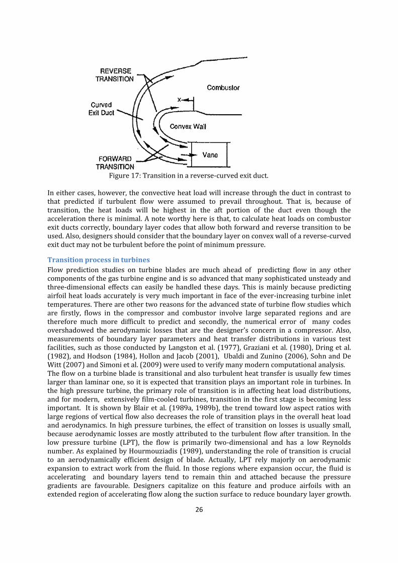
26
Figure 17: Transition in a reverse-curved exit duct. In either cases, however, the convective heat load will increase through the duct in contrast to that predicted if turbulent flow were assumed to prevail throughout. That is, because of transition, the heat loads will be highest in the aft portion of the duct even though the acceleration there is minimal. A note worthy here is that, to calculate heat loads on combustor exit ducts correctly, boundary layer codes that allow both forward and reverse transition to be used. Also, designers should consider that the boundary layer on convex wall of a reverse-curved exit duct may not be turbulent before the point of minimum pressure.
Transition process in turbines
Flow prediction studies on turbine blades are much ahead of predicting flow in any other components of the gas turbine engine and is so advanced that many sophisticated unsteady and three-dimensional effects can easily be handled these days. This is mainly because predicting airfoil heat loads accurately is very much important in face of the ever-increasing turbine inlet temperatures. There are other two reasons for the advanced state of turbine flow studies which are firstly, flows in the compressor and combustor involve large separated regions and are therefore much more difficult to predict and secondly, the numerical error of many codes overshadowed the aerodynamic losses that are the designer’s concern in a compressor. Also, measurements of boundary layer parameters and heat transfer distributions in various test facilities, such as those conducted by Langston et al. (1977), Graziani et al. (1980), Dring et al. (1982), and Hodson (1984), Hollon and Jacob (2001), Ubaldi and Zunino (2006), Sohn and De Witt (2007) and Simoni et al. (2009) were used to verify many modern computational analysis. The flow on a turbine blade is transitional and also turbulent heat transfer is usually few times larger than laminar one, so it is expected that transition plays an important role in turbines. In the high pressure turbine, the primary role of transition is in affecting heat load distributions, and for modern, extensively film-cooled turbines, transition in the first stage is becoming less important. It is shown by Blair et al. (1989a, 1989b), the trend toward low aspect ratios with large regions of vertical flow also decreases the role of transition plays in the overall heat load and aerodynamics. In high pressure turbines, the effect of transition on losses is usually small, because aerodynamic losses are mostly attributed to the turbulent flow after transition. In the low pressure turbine (LPT), the flow is primarily two-dimensional and has a low Reynolds number. As explained by Hourmouziadis (1989), understanding the role of transition is crucial to an aerodynamically efficient design of blade. Actually, LPT rely majorly on aerodynamic expansion to extract work from the fluid. In those regions where expansion occur, the fluid is accelerating and boundary layers tend to remain thin and attached because the pressure gradients are favourable. Designers capitalize on this feature and produce airfoils with an extended region of accelerating flow along the suction surface to reduce boundary layer growth.

27
Following this accelerating region is a short region of diffusion. This results in so-called “aft-loaded” airfoil (Sharma et al., 1982). As the turbine operation changes from sea level takeoff to cruise, the most critical changes occur in the low-pressure turbine. The reason is that, the operating Reynolds numbers are low at high altitudes to begin with and a further decrease can cause separation to occur before transition. That is why, the role of transition in LPT is almost similar to that in compressors undergoing large variations in mass flow than to that in a high pressure turbine. As a result, various mechanisms of transition in compressors discussed earlier can directly be applied to LPT. Here we discuss first the salient features of transitional flow in high pressure turbine (HPT) and later LPT one will be discussed.
(a) flow in high pressure turbines:
Referring Figure 18 (Mayle, 1991), a mid-span pressure distribution for a typical high-pressure turbine airfoil, it can be seen after an initial variation, the pressure on the pressure side is nearly constant until mid chord and then decreases. On the suction side, the pressure gradient is favouable over much of the forward portion of the airfoil and slowly adverse over the remaining half. The ratio between the distances of favourable and adverse pressure gradients (forward or aft loaded has always been a question for designers, really depends on one’s view of transition. This was shown by Sharma et al. (1982) who investigated the boundary layer development on a surface for both forward and aft-loaded type pressure profiles.
Figure 18: Pressure distributions for a typical high-pressure turbine airfoil. The variation in pressure near the leading edge, a consequence of the change in surface curvature there, is always found on turbine airfoils and happens on either the pressure or suction sides or both. It is particularly noticeable on high-pressure turbine airfoil, where large leading edges are designed in order to reduce the heat load and provide space for internal cooling schemes. As in compressors, and on airfoils without film cooling, small laminar separation bubbles may occur here (Figure 19), which generally have little effect unless, they are source of an unsteady, wake-induced transition (Dring et al., 1986). In some situations, however, a short bubble with turbulent reattachment is found (Bellows and Mayle, 1986). For airfoils with a film-cooled leading edge, Mick and Mayle (1988) have shown that bubbles do not occur.

28
Figure 19: Cartoon of separation bubble formation on the suction surface of a turbine blade.
(b) flow in low pressure turbines
The flow on a low-pressure turbine airfoil within a typical operating range of Reynolds numbers is shown in Figure 19 (Mayle 1991). At high Reynolds numbers, transition occurs far enough upstream that the flow is turbulent over most of the airfoil. Near the trailing edge, depending on design, turbulent separation may happen. With decreasing Reynolds number, any turbulent separation disappears and transition (via the bypass mode) moves downstream. This is shown on right side of Figure 20, i. e., fully attached flow with transition. The loss corresponding to this flow is lowest. With further decrease in Reynolds number, laminar separation ahead of transition becomes possible. If separation does occur, the bubble is short and the flow reattaches as turbulent. In this case (shown in middle of the figure), the loss is only slightly higher than previous case. For lower Reynolds numbers, the laminar shear layer and transition length increase until reattachment before the trailing edge is no longer possible and the airfoil completely separates (see left side of Figure 20).
Figure 20: Transition on a low-pressure turbine airfoil at various Reynolds number.
The aim of the designer, of course, is to design an airfoil that provides the lowest loss through its operating range This requires one to predict the Reynolds number at which the separation bubble “bursts” and the losses change dramatically. That is, one must be able to predict separated-flow transition. (Mayle….Halstead..) Recent extensive studies (e. g.: Suzen et al., 2003, Mcquilling 2007, Hollon and Jacob 2001, Sohn and Dewitt 2007, Ries et al. 2009, Sanders et al., 2011, Hodson and Howell, 2005) on transition phenomena in low pressure turbines shows that, on both experimental and computational areas

29
there are wide scopes of research which definitely could throw some light on this fundamental problem and non the less the gas turbine engine designers will be benefited.
Effects of different parameters on the flow Before discussing the effects of controlling parameters on transitional flow, it is necessary once more to explain briefly the different transition schemes under various flow conditions. Figure 21 shows different transition process modes (Halstead et al. 1997).
Figure 21: Schematics of transition process The process of Tollmien-Schlichting, or “natural” attached-flow transition, is shown Figure 20(a). For very low free-stream disturbance where turbulence intensity is less 1.0 percent, the laminar boundary layer develops linear oscillations of well-defined frequency when the Reynolds number exceeds a critical value. This is shown as region 1 in the figure. These oscillations, called Tollmien-Schlichting (TS) waves, are two-dimensional and convect at a typical speed of 0.30-0.35 V∞ . As the amplitude of the (TS) waves increases, spanwise distortions of the vertical structure develop (region 2) and grow in an increasing three-dimensional and nonlinear manner (region 3). They eventually burst into turbulent spots (region 4). Within this region, the boundary layer alternates between laminar and turbulent states. Eventually the turbulent spots originating from different locations merge and form a fully developed, continuously turbulent

30
boundary layer as transition is completed (region 5). However, when the formation and amplification process of two-dimensional TS waves in natural transition is “bypassed” due to the presence of forced disturbances of sufficient amplitude, another mode of transition which is called “bypassed transition” will occur Sources of such disturbances include higher free-stream turbulence and surface roughness. In this mode of transition, TS waves are less evident, if present at all. Rather, the first indication of transition may be the direct formation of turbulent spots thus “bypassing” region 1-3 of Figure 21(a). This process significantly reduces the length of unstable laminar flow and will promote earlier transition. Under certain circumstances (e.g., at high positive or negative incidence, rapid diffusion or low Reynolds number) The laminar boundary layer may separate from the airfoil surface. Rapid transition then occurs within the separated shear layer. Provided the Reynolds number is not too low or the local pressure gradient too large, the resulting turbulent-like layer will reattach to form a closed region of separated flow called a “separation bubble” (Roberts, 1980). The region beneath the separated laminar shear layer within the bubble is quiescent, with very low wall shear stress and nearly constant static pressure. This process is shown schematically in Figure 21(b). It is believed that, the onset of transition is completely controlled by free-stream turbulence and unsteadiness. On the other hand, it appears that the turbulent spot production rate is controlled by the pressure gradient at onset, turbulence, and whether or not the flow separates. Surface roughness, surface curvature, flow divergence or convergence, compressibility, heat transfer, and film cooling do have an effect on the production rate, but it is generally five to ten times less than that of the pressure gradient. If the flow separates, transition is primarily controlled by the momentum thickness Reynolds number at separation and the parameters that affect the length of the laminar shear layer in the bubble. These parameters are not really known, but it seems that free-stream turbulence is on of them. A discussion of all the above mentioned controlling parameters is given below.
Effect of free-stream turbulence
The effect of turbulence level on the spot production rate is shown in Figure 22. As might be expected, the production of turbulent spots increases as Tu increases.
Figure 22: Spot production rate as a function of the free-stream turbulence level for zero pressure gradient flows (Mayle, 1991).
The effect of free-stream turbulence level on the momentum thickness Reynolds number at transition, Reθt, is shown in Figure 23. As is well known, the effect of turbulence is to reduce the Reynolds number at which transition begins.

31
Figure 23: Momentum thickness Reynolds number at the onset of transition as a function of free-stream turbulence level for zero pressure gradient (Mayle, 1991). An experimental and analytical study has been performed on the effect of Reynolds number and free-stream turbulence on boundary layer transition location on the suction surface of a controlled diffusion airfoil (CDA) by Schreiber et al. (2002). Their results in Figure 24 illustrate that the transition onset location is most sensitive on the Reynolds number when the turbulence levels are between about 2 and 4 percent. Beyond Tu=4 percent the transition onset location for a given Reynolds number is more or less insensitive to higher Tu levels.
Figure 24: Influence of Reynolds number and free-stream turbulence on suction side transition onset . Choi et al., (2004) investigated the effect of free-stream turbulence on heat transfer and pressure coefficients of a turbine blade in low Reynolds number flows. This study documents the effect of increasing Reynolds number and free-stream turbulence in suppressing separation, promoting boundary layer transition, and enhancing heat transfer on blade surfaces. Predictions for the effects of free stream turbulence on turbine blade heat transfer carried out by Boyle et al. (2004). Four models for predicting the effects of free-stream turbulence were incorporated into a Navier- Stokes CFD analysis. Predictions were compared with experimental

32
data in order to identify an appropriate model for use across a wide range of flow conditions. Their results show that, high turbulence levels often result in suction surface transition upstream of the throat, while at low to moderate Reynolds numbers the pressure surface remains laminar. Experimental studies on bypass transition of separated boundary layer on low-pressure turbine airfoils, focusing on the effects of free-stream turbulence on the transition process carried out by Taniguchi et al., (2010). The results of this experimental study show that the location of boundary layer separation does not strongly depend on the free-stream turbulence level. However, as the free-stream turbulence level increases, the size of separation bubble becomes small and the location of turbulent transition moves upstream. The size of separation bubble becomes small as the Reynolds number increases. At low free-stream turbulence intensity, the velocity fluctuation due to Kelvin-Helmholtz instability is observed clearly in the shear layer of the separation bubble. At high free-stream turbulence intensity, the streak structures appear upstream of the separation location, indicating bypass transition of attached boundary layer occurs at high Reynolds number.
Effect of pressure gradient
Transition studies in flows with different types of pressure gradients are comparatively very few. Most of these works are carried out at low turbulence levels, a review of which could be found in Brown and Martin (1979). Abu-Ghannam and Shaw (1980), have done a more comprehensive measurements. Measurements in favourable pressure gradients by Blair (1982) from which both the onset of transition and the spot production rate may be determined is shown in Figure 25.
Figure 25: Combined influence of streamwise pressure gradient and free-stream turbulence intensity on boundary layer transition.

33
The data for transition onset Reynolds number are compared to the theoretical predictions of van Driest and Blumer (1963). There is a good agreement between the experimental results and the theoretical one for both constant velocity and accelerating cases. The intermittency measurements of Sharma et al. (1982) in an adverse pressure gradient condition shows (see Figure 26) good matching of the measurements data with Dhawan and Narasimha’s correlation (1956). It indicates that the distribution of intermittency factor in transitional flows is independent of the free-stream pressure gradient.
Figure 26: Wall intermittency factor distribution in the transition zone. Gostelow and co-workers (Gostelow, 1989; Gostelow and Blunden, 1989; Gostelow and Walker, 1991) and more recently Gostelow and Thomas, 2006) carried out extensive measurements to investigate the effect of adverse pressure gradient on transitional flow applied to turbomachinery. They also made intermittency measurements and their results showed good agreement with the universal intermittency distribution. The effect of acceleration on the onset of transition is presented in Figure 27 (Mayle 1991). In general, Reθt increases with either an increase in acceleration or a decrease in the free-stream turbulence level. For low turbulence levels, the effect of acceleration is significant, while for levels found in gas turbines, it is negligible. That is, at the high levels obtained in gas turbines, the onset of transition is controlled by the free-stream turbulence. This was found for all the other parameters thought to govern transition. For accelerating flows, Blair (1982) and Sharma (1987) determined that the length of transition is different for the thermal and momentum boundary layers. The effect produces a longer transition for the thermal boundary layer than for the momentum boundary layer in flows developing under favourable pressure gradients, while the reverse is true in flows developing under adverse pressure gradients.
Figure 27: The Reyonlds number of transition as a function of the acceleration parameter

34
Effect of surface roughness
Surface imperfections on in-service gas-turbine blade rows can have a significant effect on the blade-passage flow (e.g., Leipold et al.; Bons and McClain (2000, 2003)). The main causes of roughness on turbine blades are hydrocarbon deposits and erosion due to impact with small particles. The level of surface roughness on a gas-turbine blade, which can vary in height from 2 to 160 µm (Bons et al., Taylor (2001, 1990)), depends on the location of the blade within the engine, and the length of time it has been in service. The distribution of roughness over the blade surface is typically non-uniform, with significant variations in both the streamwise and spanwise directions (e.g., Bons et al.; Taylor (2001, 1990)). For example, the roughness level at the leading edge of a high pressure- turbine stator blade (Figure 28(a)) is noted to be of larger scale than that observed near the suction peak of a low-pressure turbine rotor blade (Figure 28(b)) from the same engine. Closer proximity to the combustor and more rapid accumulation of roughness in stagnation regions are responsible for the rougher surface conditions noted near the leading edge of the stator blade. Modification of the blade-surface boundary layer by surface roughness has been shown to reduce turbine aerodynamic efficiency (e.g., Kind et al.; Boynton et al.; Suder et al. (1998, 1992, 1995)), and increase the surface heat-transfer rate (e.g., Bons and McClain; Blair, Pinson, and Wang; Wang and Rice (2003, 1994, 1997, 2003)). Blade-surface heat transfer rates may also be affected by changes in the surface material properties when the roughness is due to hydrocarbon deposits, or when a protective coating is eroded. Understanding the effects of surface roughness is essential for predicting in-service aerodynamic performance, and thus optimizing blade designs for maximum operational efficiency and life. One means by which surface roughness may affect the flow field is through its influence on the transition of the blade-surface boundary layer from a laminar to a turbulent state. Sufficiently large surface roughness is known to “trip” the laminar boundary layer, after which a very rapid transition process takes place (e.g., Gibbings et al.(1986, 1986, 1986), Klebanoff and Tidstrom (1982)). If the roughness level is insufficient to trigger immediate transition inception, as is often the case with low-pressure turbine blades, the location of transition inception in an attached boundary layer moves progressively upstream with increases in surface roughness (e.g., Pinson and Wang; Gibbings and Al Shukri; Kerho and Bragg (1997, 1997, 1997). Similar trends have also recently been observed in separation-bubble transition (Roberts and Yaras; Volino and Bohl (2005, 2004)). For a given surface roughness height, the geometry of the roughness pattern may have a significant effect on how the boundary-layer development is affected by the surface conditions. It was suggested by Morris (1955) that the effect of roughness on the boundary layer occurs primarily through vorticity and turbulence shed in the wakes of roughness elements. The influence of this wake turbulence on the surrounding flow, and the extent by which neighboring wakes interact, are affected by the shape, size, and spacing of the roughness elements. The effects of these features of roughness patterns on turbulent boundary layers have been studied extensively for both deterministic (e.g., Waigh and Kind; Dirling Dvorak (1998, 1973, 1969)), and random (e.g., Bons; Belnap et al.; Sigal and Danberg (2002, 2002, 1990)) roughness. The recent experiments of Stripf et al. (2005) over deterministically rough surfaces suggest the roughness geometry to be less influential in transitional flows than in fully turbulent boundary layers. Nonetheless, movement of the location of transition inception with variations in roughness spacing is evident in their experimental data, with the effect of spacing becoming less pronounced at the highest Reynolds numbers and turbulence levels tested. In a recent study on the effects of stochastic roughness on separation-bubble transition conducted by the Roberts and Yaras (2005), transition inception generally occurred further upstream with increased roughness height. However, a reversal of this trend was observed for two of the surfaces included in the study, which was attributed to differences in the spacing of the roughness elements. The above-noted effects of surface roughness on the location of transition inception in separation bubbles must occur through modification of the mechanism causing instability. In small separation bubbles, where the shear layer is located relatively close to the surface, a significant effect of wall damping on the shear layer remains. In these instances, transition

35
inception is preceded by the growth of Tollmien-Schlichting (T-S) instability waves (e.g., Roberts and Yaras; Volino and Bohl; Volino (2005, 2004, 2002)), which may break down and form turbulent spots characteristic of natural transition in attached boundary layers. The Λ vortices normally associated with natural attached-flow transition have also been observed in separated shear layers (Bao and Dallmann (2004)). As the separated shear layer moves away from the surface, the damping of the wall becomes less pronounced, and the flow begins to more closely resemble a free shear layer, in which the inviscid Kelvin- Helmholtz (K-H) instability mechanism is expected to dominate (e.g., Malkiel and Mayle; Watmuff; Yang and Voke; Spalart and Strelets (1996, 1999, 2001, 2000)). Computational studies of separated boundary layers have shown that the distance of the shear layer from the surface, the thickness of the shear layer, and the flow Reynolds number are all factors affecting the dominant instability mode (e.g., Rist and Maucher; Chandrasekhar (2002, 1961)). Published studies on boundary-layer transition do not provide information from which the effects of roughness geometry on the transition process in separation bubbles may be derived for the stochastically rough surfaces typical of turbomachinery blades.
Figure 28: Surface roughness at the leading edge of a HP turbine nozzle (a), and near the suction peak of a LP turbine blade (b). Note: magnification is higher in (b). Also it is to be mentioned one of the few work which has been done on effect of “distributed” roughness on transitional flow is that of Feindt (1956) and later by Mick (1987). Figure 29 shows the results of their studies for various sized engines. The interesting outcome of this figure is that, since turbulence causes an earlier onset of transition than roughness for all engines, except perhaps the small engines and the low-pressure turbine under the worse conditions, the effect of roughness on the onset can generally be neglected. Figure 29: A comparison between the effects of roughness and free-stream turbulence for various sized engines.

36
Effect of curvature
The effect of curvature on transition were studied rather early by Görtler (1940), who considered the theoretical aspects of stability, and Liepmann (1943), who carried out experiments. Görtler found out that a laminar boundary layer on a concave surface becomes unstable as a results of centrifugal forces to three-dimensional disturbances and formed streamwise vortices within the layer. Liepmann showed that transition on a convex surface is only slightly delayed, as did the experiments of Wang and Simon (1985), but it may occur substantially earlier on a concave wall. Although all of this work was done at relatively low turbulence levels, it follows that the onset of transition on a convex surface at higher free-stream turbulence levels will be virtually identical to that for a flat plate. For Tu=0.03, Liepmann found that transition occurred on a concave surface when Gö=Reθt√θ∕r≥7 where Gö is Görtler number and r is the radius of curvature. Later, measurements on concave surfaces at higher turbulence levels reported by Riley et al. (1989). Their results together with Liepmann’s are shown in Figure 30. In this format, all straight lines passing through the origin corresponds to a constant Görtler number and transition for any turbulence level occur when Reynolds number lies close to Gö=7 line. Liepmann’s data lie close to Gö=7 line. The rise in transition Reynolds number above this line found by Riley et al. is caused by the Görtler vortices increasing the velocity gradients near the wall thereby delaying transition. For highly curved surfaces, this effect dominates that of turbulence. It may be said, that concave curvature can either decrease, as found by Liepmann, or increase the transition Reynolds number depending on strength of curvature and turbulence intensity.
Figure 30: Reynolds number at the onset of transition on a concave surface as a function of the curvature parameter.

37
Effect of flow divergence or convergence
Streamline convergence and divergence are known to produce large effects on turbulent boundary layer growth, and so may be expected to have similarly large effects on transition characteristics as well. While modelling the transition zone in flows with non-parallel streamlines, it is often assumed that the spot propagation envelope is inclined at a constant angle to the local streamline, the angle being therefore the same as in two-dimensional flows; this assumption goes back to the work of Emmons and Bryson (1952), and has been adopted by Chen and Thyson (1971) in their widely use transition zone model. It has been pointed out (Narasimha, 1985) that this hypothesis predicts extremely rapid growth in divergent flow: if the divergence is of the radial source type, the turbulent “wedge” swept out by the spot would be a
logarithmic spiral, and it edges would come together at an azimuth 180: away from the point of spot generation. The detailed experiments carried out by author (Jahanmiri et al. 1995,1996) on a turbulent spot in a distorted duct to study the effects of a divergence with straight streamlines preceded by a short stretch of transverse streamline curvature, both in the absence of any pressure gradient. It is found that the distortion produces substantial asymmetry in the spot (see the Figure 31), however, there is no strong effect on the internal structure of spot and the eddies therein. Or on such propagation characteristics as overall spread rate and the eddies and the celebrities of the leading and trailing edges. Both lateral streamline curvature and non-homogeneity of the laminar boundary layer into which the spot propagates are shown to be strong factors responsible for the observed asymmetry. It is concluded that these factors produce chiefly a geometric distortion of the coherent structure in the spot, but do not otherwise affect its dynamics in any significant way.
Figure 31: Normalized spot shape plan view at y=0.5mm and different time instants. Intermittency measurements are made by Ramesh et al. (1996) in the transition zone of a three-dimensional constant pressure diverging flow (similar to Jahanmiri et al. set up) in order to study the effect of lateral strain rate on the intermittency distribution. Measured intermittency data are found to follow the two-dimensional behaviour thus indicating that the lateral strain rate does not affect the normalized intermittency distribution in the transition zone. Later measurements of Vasudevan et al. (2001) in a laterally converging constant pressure flow also

38
showed that the streamline convergence does not affect two-dimensional spot propagation characteristics. So by these experiments, it may be concluded that the flow divergence or convergence has least effect on transitional flow dynamics.
Effect of compressibility
There are not much experimental data on this issue, although not mentioned, most of results were obtained in low turbulence levels. Most of efforts concentrated on obtaining an onset Reynolds number and transition length by measuring either distribution of surface shear stress or heat transfer, and later through surface intermittency detection methods. Narasimha (1985), analyzed all previous data and shows in his figure 35 (see Figure 32). In this figure, Owen (1970) defines three transition zone Reynolds numbers, at onset, peak and end respectively, based on the fluctuating signals from a surface film gauge. His data on onset Reynolds numbers in the Mach number range 2.5 to 4.5 show a slow increase with Mach number, and are generally consistent with the ZK data. However, especially at the high end of this Mach number range, Owen finds a much more rapid increase of Rexe with Mach number. This figure also shows the data of Nagamatsu et al. (1967) at higher Mach numbers (8 to 16). Both Reb and Ree increase significantly with Mach number; the Reb data on a smooth cone would be consistent with those of Owen (1970) as well as Owen et al. (1975). The conclusions that stand out beyond reasonable doubt are that at Mach numbers beyond about 5, both Reb and Ree increase rapidly, but by a Mach number of about 15 the rate of increase has declined. Furthermore, by comparing the data at, say, Mach 7 with those at Mach 0, it is reasonably certain that at the same onset Reynolds number the transition zone is longer at the higher Math number.
Figure 32: An overview of experimental data at different Mach numbers on Reynolds numbers at onset and end of transition (Dey and Narasimha, 1985). More recently Walsh and Davies (2005) carried out measurements in the transition region of a turbine blade profile under compressible conditions. They concluded that, all the intermittency measurements in the choked flow experiments were found to fall on a linear F(γ) line for the current data set. This interesting result would need further validation before its widespread use was feasible. The introduction of correlations to include the effect of Mach number for transition onset, in general, resulted in better agreement with the measurements. Again, further experimental evidence is needed under a variation of conditions to fully resolve this issue. So, it

39
is conjectured that, the effect of Mach number on the transition region needs more studies before prediction methods can be used reliably.
Effect of heat transfer
Heating or cooling the flow is known to affect boundary layer transition at low intensity of free-stream turbulence. Liepmann and Fila (1947) measurements on air flowing along a heated wall showed that, an increased temperature of the wall will hasten the transition process. But because transition occurred via the natural transition mode, their result may have less importance for gas-turbine engines application. Martin and Brown (1979) suggested that heat transfer through the laminar boundary layer flowing over the concave pressure surface of a turbine blade is strongly influenced by the presence of Taylor-Göertler vortices, as well as by mainstream turbulence. Transition occurs when these factors in concert outweigh the tendency of the boundary layer to remain laminar in the favourable pressure gradients characteristic of flow over pressure surfaces. Experiments by Rüd and Witting (1986) on a cooled surface appropriate to the gas-turbine situation shows for Tu>2, the effect of Tw/T∞ on either the onset or length of transition is negligible. This effect on Reθt is not difficult to understand considering the negligible effect at high turbulence levels for flows with pressure gradients. The insignificant effect on the length of transition implies that the spot production rate is unaffected by the heat transfer at high free-stream turbulence intensities.
Effect of film cooling
Film cooling is supposed to affect the state of the boundary layer on a gas turbine blade. At injection ports the film holes are usually much larger than the boundary layer thickness in such a way that injection of coolant into the flow through series of holes completely disrupts the flow close to the surface and provides a source of high turbulence within the downstream developing boundary layer. Therefore, it may be said that film cooling effect is to “trip” a laminar boundary layer and initiates transition to turbulence. Figure 33 after Mayle (1991), shows this effect, where heat transfer results both with and without film cooling have been plotted for film cooling on the leading edge of an airfoil. It can be seen, for no injection, holes covered, a separated-flow transition occurs near x/D≈π/4, (D is leading edge diameter). With blowing, however, and in spite of the high acceleration, it seems that neither a laminar boundary layer exists nor a forced transition occurs except that caused by the injection itself. Measurements of Mehendale et al. (1991) at high main-stream turbulence confirms the above mentioned findings.
Figure 33: Effect of film cooling on transition

40
Warren and Metzger (1972) have shown that, for situations where the acceleration downstream of injection is sufficient to cause reverse transition, the heat transfer approaches that for laminar flow. This implies that even though injection can initiate transition, a subsequent strong acceleration can cause the flow to become laminar again. Such a situation is common for film-cooled airfoils in the first stages of the turbine. Recent heat transfer measurements of Colban et al. (2006, 2007) on a stator vane, indicated that the behavior of the boundary layer transition along the suction side of the vane showed sensitivity to the location of film-cooling injection, which was simulated through the use of a trip wire placed on the vane surface.
Conclusion The present overview on transitional flow in gas turbines had many-fold results that can be summarized as below: 1 Modelling unsteady transition is one of the major problems that need to be pursued. Unsteady transition onset for compressor blades, and the leading edge interaction effects associated with wake passing, are being addressed; the modelling of subsequent transitional flow remains to be incorporated. 2 Turbine blade optimisation models currently incorporate the unsteady effects of wake-induced transition, but not the transitional flow effects associated with spot merging. 3 Compressor blade optimization studies have been reported for steady flow conditions, but still lack accurate transitional flow models; true optima may not have been reached, even under steady conditions. 4 It may be time to undertake a more detailed experimental study of the influence of free-stream turbulence on turbulent breakdown, informed by recent DNS studies and using modern observation techniques. 5 Experimental data for transitional flow under accelerating flow conditions remains poor, as does data on re-laminarization and its prediction. 6 The presence of streamwise vorticity, on both concave and convex surfaces, and its effects on boundary layers and heat transfer is still not well recognized, understood or predicted. 7 Transition information obtained at low free-stream turbulence levels is vitually useless for the gas-turbine designer. 8 previous assumptions of predominantly turbulent boundary layers on multistage turbomachine blading were convincingly proved to be incorrect. Along both paths the boundary layer clearly goes from laminar to transitional to turbulent, with great extents of laminar and transitional flow being found in results of Halstead et al. (1997). 9 Transition in gas turbines is controlled mainly by the free-stream turbulence, pressure gradient, and the periodic, unsteady passing of wakes. 10 The higher shear stress in the calmed region is effective in suppressing flow separation and delaying transition onset in the region between wakes. 11 The onset of transition in gas turbine depends only on free-stream turbulence, the periodic unsteady effect of wakes and shock waves, and whether the acceleration is greater or less than that for reverse transition. 12 The length of transition in gas turbines depends only on the free-stream turbulence and pressure gradient. 13 The effects of surface roughness, surface curvature, flow divergence or convergence, compressibility, and heat transfer on transition in gas turbines are less significant as compared to free-stream turbulence effect. 14. Transition in gas turbines in an accelerating flow region is always of the bypass type. This can certainly be said for transition in most gas turbine flows except that near separation. Finally to say, although in recent years many research activities on this issue were accomplished but some more areas still open for further studies like: experiments on separated-flow transition

41
at high turbulence intensity; experiments to be conducted for determination of a design criterion for the onset of wake induced transition; determining acceleration parameter, free-stream turbulence level and turbulent length scale at the transition onset location; and investigation on effect of blade leading edge curvature on transition onset.
Acknowledgements First of all, I should thank Prof. R. E. Mayle for his valuable review paper (Mayle, 1991) and the
others whom the results were taken directly from their publications. I am also thankful to Dr.
Valery Chernoray for his help and suggestions. This work is supported by Dept. of Applied
Mechanics, Chalmers University of Technology and; Shiraz University of Technology.
Reference Abu-Ghannam, B. J., and Shaw, R., (1980) ‘‘Natural Transition of Boundary Layers—The Effect of Turbulence, Pressure Gradient and Flow History,’’ J. Mech. Eng. Sci., 22, No. 5, pp. 213–228.
Ames, F. E., (1994) “Experimental Study of Vane Heat Transfer and Aerodynamics in Elevated Levels of Turbulence” NASA Contract Report No. 4633.
Anthony, R. J., Jones, T. V., LaGraff, J. E., (2005) ” High Frequency Surface Heat Flux Imaging of Bypass Transition” Transactions of the ASME, J. of Turbomachinery 127: 241-250.
Ashworth, D. A., LaGraff, J. E., Shultz, D. L., and Grindrod, K. J., (1985) ‘‘Unsteady Aerodynamic and Heat Transfer Processes in a Transonic Turbine Stage’’ ASME J. Eng. Gas Turbines Power, 107, pp. 1022–1030.
Bao, F., and Dallmann, U. C., (2004) “Some Physical Aspects of Separation Bubble on a Rounded Backward-Facing Step,” Aerosol Sci. Technol., 8, pp. 83–91.
Bario, F. , Beral, C., (1998) ” Boundary layer measurements on the pressure and suction sides of a turbine inlet guide vane” Experimental Thermal and Fluid Science 17, 1-9.
Bellows, W. J., and Mayle, R. E., (1986) “Heat transfer downstream of a leading edge separation bubble” ASME J. of Turbomachinery, vol. 108, pp. 131-136.
Belnap, B. J., van Rij, J. A., and Ligrani, P. M., (2002) “A Reynolds Analogy for Real Component Surface Roughness,” Int. J. Heat Mass Transfer, 45, pp. 3089–3099.
Blair, M. F., (1982) ‘‘Influence of Free-Stream Turbulence on Boundary Layer Transition in Favorable Pressure Gradients,’’ ASME J. Eng. Power, 104, pp. 743–750.
Blair, M. F., (1994) “An Experimental Study of Heat Transfer in a Large Scale Turbine Rotor Passage,” ASME J. Turbomach., 116, pp. 1–13.
Blair, M. F., Dring, R. P., and Joslyn, H. D., (1989a) “The effect of turbulence and stator/rotor interactions on turbine heat transfer: Part 1-Design operating conditions” ASME J. of Turbomachinery, vol. 111, pp. 87-96.
Blair, M. F., Dring, R. P., and Joslyn, H. D., (1989b) “The effect of turbulence and stator/rotor interactions on turbine heat transfer: Part 2-Effects of Reynolds number and incidence” ASME J. of Turbomachinery, vol. 111, pp. 97-103.
Blair. M. F., (1992) “Boundary layer in accelerating flows with intense free-stream turbulence” submitted for publication in the J. Fluid Mechanics. Part 1 and 2, 114: 313-332.
Bons, J. P., (2002) “St and cf Augmentation for Real Turbine Roughness With Elevated Freestream Turbulence,” ASME GT2002-30198.
Bons, J. P., and McClain, S. T., (2003) “The Effect of Real Turbine Roughness With Pressure Gradient on Heat Transfer,” ASME J. Turbomach., 126, pp. 333–441.

42
Bons, J. P., McClain, S. T., Taylor, R. P., and Rivir, R. B., (2001) “The Many Faces of Turbine Surface Roughness,” ASME J. Turbomach., 123, pp. 739– 748.
Bons, J. P., Reimann, D., Bloxham, M., (2008) “Separated Flow Transition on an LP Turbine Blade With Pulsed Flow Control” Transaction of the ASME, J. of Turbomachinery vol.130, pp.1-8.
Boyle, R.. J., Giel, P. W., Ames, F. E., (2004) “Predictions for the Effects of Free Stream Turbulence on Turbine Blade Heat Transfer” NASA/TM—2004-213079.
Boynton, J. L., Tabibzadeh, R., and Hudson, S. T., (1992) “Investigation of Rotor Blade Roughness Effects on Turbine Performance,” ASME J. Turbomach., 115, pp. 614–620.
Brown , B., and Martin, B. W., (1979) “Heat transfer to turbine blades, with special reference to the effect of mainstream turbulence” ASME Paper No. 77-GT-48.
Cardamone, P., (2006) ” Aerodynamic Optimisation of Highly Loaded Turbine Cascade Blades for Heavy Duty Gas Turbine Applications” Ph.D. thesis, Universität der Bundeswehr München Fakultät für Luft- und Raumfahrttechnik Institut für Strahlantriebe.
Chandrasekhar, S., (1961) Hydrodynamic and Hydromagnetic Stability, Clarendon Press, Oxford.
Chen, K. K., and Thyson, N. A., (1971) “Extension of Emmons spot theory to flows on blunt bodies” AIAA J. 5:821-825.
Choi, J., Teng, S., Han, J. C., Ladeinde, F., (2004) “Effect of free-stream turbulence on turbine blade heat transfer and pressure coefficients in low Reynolds number flows” International J. of Heat and Mass Transfer 47 : 3441–3452.
Colban, W., Gratton, A., Thole, K. A., and Haendler, M., (2006) “Heat Transfer and Film-Cooling Measurements on a Stator Vane With Fan-Shaped Cooling Holes,” ASME J. Turbomach., vol. 128, pp. 53–61.
Colban, W., Thole, K. A., and Haendler, M., (2007) “Experimental and Computational Comparisons of Fan-Shaped Film Cooling on a Turbine Vane Surface” ASME J. Turbomach., vol. 129, pp. 23-31.
Coles, D., (1954) “Measurements of turbulent friction on a smooth flat plate in supersonic flow” J. Aero. Sci. 21, 433-448.
Crabtree, L.F., (1958) "Prediction of Transition in the Boundary Layer on an Aerofoil," J. Roy. Aero. Soc., 62,.
Cumpsty, N. A., Dong, Y., and Li, Y. S., (1995) ‘‘Compressor Blade Boundary Layers in the Presence of Wakes,’’ ASME Paper No. 95- GT-443.
D’Ovidio, A., Harkins, J.A. & Gostelow, J.P., (2001a) "Turbulent Spots in Strong Adverse Pressure Gradients, Part 1 - Spot Behavior," ASME-2001-0194.
D’Ovidio, A., Harkins, J.A. & Gostelow, J.P., (2001b) "Turbulent Spots in Strong Adverse Pressure Gradients, Part 2 - Spot Propagation and Spreading Behavior," ASME-2001-0406.
Dey, J. and Narasimha, R., (1985) “Spot formation rates in high speed flows” Report 85 FM 11, Dept. Aero. Eng., Ind. Inst. Sci., Bngalore, India.
Dhawan S., Narasimha R., (1958) “Some properties of boundary layer flow during transition from laminar to turbulent motion” J. Fluid Mech., 3, 418-436.
Dirling, R. B. J., (1973) “A Method for Computing Rough Wall Heat Transfer Rates on Reentry Nosetips,” AIAA J., 73–763.
Dong, Y. and Cumpsty, N. A., (1989) “Compressor Blade Boundary Layers: Part I; Test Facility and Measurements with No Incident Wakes ; Part II Measurements with Incident Wakes” ASME papers 89-GT-50 and 89-GT-51.

43
Dong, Y., and Cumpsty, N. A., (1990a) ‘‘Compressor Blade Boundary Layers: Part 1—Measurements With No Incident Wakes,’’ ASME J. Turbomach., 112, pp. 222–230.
Dong, Y., and Cumpsty, N. A., (1990b) ‘‘Compressor Blade Boundary Layers: Part 2—Measurements With Incident Wakes,’’ ASME J. Turbomach., 112, pp. 231–240.
Doorly, D. J. and Oldfield, M. L. G., (1985) “Simulation of the effects of shock wave passing on a turbine rotor blade” ASME paper No. 85-GT-112.
Doorly, D. J., (1987) “Modelling the unsteady flow in a turbine rotor passage, ASME paper No. 87-GT-197 .
Drela, M. & Giles, M.B., (1987) "Viscous-Inviscid Analysis of Transonic and Low Reynolds Number Airfoils," AIAA J., 25, 1347-1355.
Drela, M., (1998)"MISES Implementation of Modified Abu- Ghannam/Shaw Transition Criterion," MIT Aero-Astro.
Dring, R. P., Blair, M. F., Joslyn, H. D., Power, G. D., and Verdon, J. M., (1986) ” The effects of inlet turbulence and rotor/stator interactions on the aerodynamics and heat transfer of a large-scale rotating turbine model” NASA CR 4079.
Dring, R. P., Joslyn, H. D., Hardin, L. W., and Wagner, J. H., (1982) ‘‘Turbine Rotor–Stator Interaction,’’ ASME J. Eng. Power, 104, pp. 729–742.
Dunn, M. G., (2001) “Convective Heat Transfer and Aerodynamics in Axial Flow Turbines,” ASME Paper No. 2001-GT-0506.
Dvorak, F. A., (1969) “Calculation of Turbulent Boundary Layers on Rough Surfaces in Pressure Gradient,” AIAA J., 7, pp. 1752–1759.
Elsner, W., (2007) ” Transition Modelling in Turbomachinery” J. of Theoretical and Applied Mechanics, 45, 3, pp. 539-556.
Elsner, W., Vilmin, S., Drobniak, S., Piotrowski W., (2004) “Experimental analysis and prediction of wake-induced transition in turbomachinery” ASME paper no. GT2004-53757, ASME TURBO EXPO 2004, Vienna.
Emmons, H.W., (1951) "The Laminar-Turbulent Transition in a Boundary Layer - Part I," J. Aero. Sci., 18, 7, 490-498.
Emmons, H. W., and Bryson, A. E., (1952) “The laminar-turbulent transition in a boundary layer, Part II” Proc J. US. Natl. Cong. Thero. Appl, Mech., 859-868.
Feindt, E. G., (1956) “Untersuchungen über die Abhängigkeit des Umschlages laminar-turbulent von Oberlächenrauhigkeit und der Druckverteilung” Schiffbautechn. Gesellschaft, vol. 50, pp. 180-203.
Gaster, M., (1969) “ The structure and behavior of laminar separation bubbles” ARC R&M 3595.
Gibbings, J. C., and Al-Shukri, S. M., (1997) “Effect of Sandpaper Roughness and Stream Turbulence on the Laminar Layer and its Transition,” Aeronaut. J., 101, pp. 17–24.
Gibbings, J. C., Goksel, O. T., and Hall, D. J., (1986) “The Influence of Roughness Trips Upon Boundary-Layer Transition—Part 1 Characteristics of Wire Trips,” Aeronaut. J., 90, pp. 289–301.
Gibbings, J. C., Goksel, O. T., and Hall, D. J., (1986) “The Influence of Roughness Trips Upon Boundary-Layer Transition—Part 2 Characteristics of Single Spherical Trips,” Aeronaut. J., 90, pp. 357–367.
Gibbings, J. C., Goksel, O. T., and Hall, D. J., (1986) “The Influence of Roughness Trips Upon Boundary-Layer Transition—Part 3 Characteristics of Rows of Spherical Transition Strips,” Aeronaut. J., 90, pp. 393–398.

44
Gleyzes, C., Cousteix, J.R. & Bonnet, J.L., (1985)"Theoretical and Experimental Study of Low Reynolds Number Transitional Separation Bubbles," Conf. on Low Reynolds Number Airfoil Aerodynamics, University of Notre Dame, IN.
Gostelow, J. P., and Thomas, R. L., (2006) “Effects of strong adverse pressure gradients and incident wakes on transition and calming” Sixth IUTAM Symposium on Laminar-Turbulent Transition, 131-138, Springer.
Gostelow, J. P., (1989) “Adverse pressure gradient effects on boundary layer transition in a turbulent free-stream” 9th Int. Symp. on Air Breathing Engines, vol. 2, pp. 1299-1306.
Gostelow, J. P., and Bluden, A. R., (1989) ‘‘Investigation of Boundary Layer Transition in an Adverse Pressure Gradient,’’ ASME J. Turbomach., 111, pp. 366–375.
Gostelow, J. P., and Walker, G. J., (1991) “Similarity behavior in transitional boundary layers over a range of adverse pressure gradients and turbulence levels” ASME J. of Turbomachinery, vol. 113.
Gostelow, J.P., Blunden, A.R. & Walker, G.J., (1994) "Effects of Free- Stream Turbulence and Adverse Pressure Gradients on Boundary Layer Transition," J. Turbomachinery, 116, 392-404.
Gostelow, J.P., Melwani, N. & Walker, G.J., (1996)"Effects of Streamwise Pressure Gradient on Turbulent Spot Development," J. Turbomachinery, 118, 737-743.
Gostelow, J.P., Walker, G.J., Solomon, W.J., Hong, G. & Melwani, N., (1997) "Investigation of the Calmed Region behind a Turbulent Spot," J. Turbomachinery, 119, 802-809.
Graziani, R. A., Blair, M. F., Taylor, J. R., and Mayle, R. E., (1980) “An experimental study of end-wall and airfoil surface heat transfer in a large scale turbine blade cascade” ASME J. of Engineering for Power, vol. 102, pp. 257-267.
Götler, H., (1940) “Über eine dreidimensionale Instabiltät laminar Grenzschichten an konkaven Wänden” Nachr. Wiss. Ges. Göttingen, Math. Phys. Klasse, Neue Folge 2, No. 1; see also ZAMM, vol. 21, 1941, pp. 250-252.
Halstead, D. E., Wisler, D. C., Okiishi, T. H., Walker, G. J., Hodson, H. P., and Shin, H. W., (1997) ‘‘Boundary Layer Development in Axial Compressors and Turbines: Part 1–4,’’ ASME J. Turbomach., 119, pp. 114–127; 426–444; 225–237; 128–139.
Halstead, D. E., Wisler, D. C., Okiishi, T. H., Walker, G. J., Hodson, H. P., and Shin, H-W., (1997) ‘‘Boundary Layer Development in Axial Compressors and Turbines: Parts 1–4,’’ ASME J. Turbomach., 119, pp. 114–127; ibid., 119, pp. 426–444; ibid. 119, pp. 234–246; ibid., 119, pp. 128–139.
Henderson, A. D., Walker, G. J., and Hughes, J. D., (2008) “Unsteady Transition Phenomena at a Compressor Blade Leading Edge” ASME Journal of Turbomachinery , vol. 130: 1-10.
Hodson, H. P. and Addison, J. S., (1988) “Wake-Boundary Layer Interactions in an Axial-Row Turbine at Off- Design Conditions” ASME paper 88-GT-233.
Hodson, H. P., (1983) “The Development of Unsteady Boundary Layers on the Rotor of an Axial-Flow Turbine”, AGARD Conf. on Viscous Effects in Turbomachines, AGARD CP-351, Copenhagen.
Hodson, H. P., (1984) “Boundary layer and loss measurements on the rotor of an axial-flow turbine” ASME J . of Engineering for Gas Turbines and Power, vol. 106, pp. 391-399.
Hodson, H. P., (1989) “Modelling Unsteady Transition and Its Effects on Profile Loss” Proceedings, AGARD Conf. PEP 74a on Unsteady Flows in Turbomachines, AGARD CP 468.
Hodson, H. P., and Howell, R. J., (2005) “The role of transition in high-lift low-pressure turbines for aeroengines” Progress in Aerospace Sciences 41: 419–454.

45
Hodson, H.P. & Howell, R.J, (2005). "The Role of Transition in High- Lift Low-Pressure Turbines for Aeroengines," Prog. Aerospace Sci., 41, 419-454.
Hollon, B. and Jacob, J.D., (2001) “Experimental investigation of separation on low pressure turbine blades” AIAA Paper No. 2001-0447, 39th AIAA Aerospace Sciences Meeting and Exhibit, Reno, Nevada.
Horton, H.P., (1969) "A Semi-Empirical Theory for the Growth and Bursting of Laminar Separation Bubbles," ARC CP 1073.
Hourmouziadis, J., (1989) ‘‘Aerodynamic Design of Low Pressure Turbines,’’ AGARD Lecture Series No. 167.
Huai, X., Joslin, R., Piomelli, U., (1997) “Large-eddy simulation of transition to turbulence in boundary layers” Theoret. Comput. Fluid Dynamics, 9, 149-163
Hughes, J. D. and Walker, G. J., (2001) “Natural Transition Phenomena on an Axial Compressor Blade” Transactions of the ASME, J. of Turbomachinery, vol. 123, pp. 392-401.
Jahanmiri, M., Prabhu, A. and Narasimha, R., (1995) “Turbulent Spot in 3-D Constant Pressure Flow”, Proc. IUTAM Symp., Sendai, Japan, (Ed. R. Kobayashi), Springer,
Jahanmiri, M., Prabhu, A. and Narasimha, R., (1996) “Experimental Studies of a Distorted Turbulent Spot in a Three-Dimensional Flow”, J. Fluid Mech.,, Vol. 329, 1–24.
Kalitzin, G., , Wu, X., Durbin, P. A., (2003) “DNS of fully turbulent flow in a LPT passage” International J. of Heat and Fluid Flow 24: 636–644.
Keller, F.J., Wang, T., (1994) “Flow and Heat Transfer Behavior in Transitional Boundary Layers with Streamwise Acceleration” ASME 94-GT-24.
Kerho, M. F., and Bragg, M. B., (1997), “Airfoil Boundary-Layer Development and Transition With Large Leading-Edge Roughness,” AIAA J., 35, pp. 75– 84.
Kestoras, M.D. Simon, T.W., (1993) “Effect of Free-Stream Turbulence Intensity on a Boundary Layer Recovering from Concave Curvature Effects” ASME 93-GT-25.
Kind, R. J., Serjak, P. J., and Abbott, M. W. P., (1998) “Measurements and Prediction of the Effects of Surface Roughness on Profile Losses and Deviation in a Turbine Cascade,” ASME J. Turbomach., 120, pp. 20–27.
Klebanoff, P. S., and Tidstrom, K. D., (1982) “Mechanism by Which a Two- Dimensional Roughness Element Induces Boundary-Layer Transition,” Phys. Fluids, 15, pp. 1173–1188.
Koller, U., Monig, R., Kusters, B., and Schreiber, H. A., (2000) ‘‘Development of Advanced Compressor Airfoils for Heavy-Duty Gas Turbines, Part I: Design and Optimization,’’ ASME J. Turbomach., 122, pp. 397–405.
Koyabu, E., Funazaki, K., and Kimura, M., (2003) “Effects of Periodic Wake Passing Upon Bypass Transition of Blade Boundary Layer and Unsteady Loss” Proceedings of the International Gas Turbine Congress-Tokyo.
Kozulovic, D., Röber, T.; Kügeler, E., Nürnberger, D., (2004) “Modifications of a Two-Equation Turbulence Model for Turbomachinery Fluid Flows” DGLR Jahrestagung, No. DGLR-JT2004-229a, Dresden.
Kusters, B., Schreiber, H. A., Koller, U., and Monig, R., (1999) ‘‘Development of Advanced Compressor Airfoils for Heavy Duty Gas Turbines, Part II: Experimental and Analytical Analysis,’’ASME J. Turbomach., 122, pp. 406–414.
Lagraff, J. E., Ashworth, D. A. and Schultz, D. L., (1989) “Measurement and Modelling of the Gas Turbine Blade Transition Process as Disturbed by Wakes, ASME J. Turbomachinery 111, 315.

46
Lakshminarayana, B., (1991) “An Assessment of Computational Fluid Dynamic Techniques in the Analysis and Design of Turbomachinery—The 1990 Freeman Scholar Lecture,” ASME J. Fluids Eng., 113, pp. 315–352
Langston, L. S., Nice, M. L., and Hooper, R. M., (1977), “Three-dimensional flow within a turbine cascade passage” ASME J. of Engineering for Power, vol. 99. pp. 21-28.
Lardeau, S., Leschziner M., (2004) “Modelling bypass transition with low- Reynolds-number nonlinear eddy-viscosity closure” Flow, Turbulence and Combustion, 73, 1, 49-76.
Leipold, R., Boese, M., and Fottner, L., (2000) “The Influence of Technical Surface Roughness Caused by Precision Forging on the Flow Around a Highly Loaded Compressor Cascade,” ASME J. Turbomach., 122, pp. 416–425.
Liepmann, H. W., (1943) “Investigations on laminar boundary layer stability and transition on curved boundaries” NACA ACR 3H30 (NACA-WR-W-107).
Liepmann, H. W., and Fila, G. H., (1947) “Investigations of effects of surface temperature and single roughness elements on boundary layer transition” NACA TN 1196.
Liu, X. and Rodi, W., (1989) “Measurements of Unsteady Flow and Heat Transfer from a Flat Plate”, ASME paper 89-GT-2.
Lodefier, K., Dick, E., (2006) “Modelling of unsteady transition in low-pressure turbine blade flows with two dynamic intermittency equations” Flow, Turbulence and, 76, 2, 103-132.
Lodefier, K., Dick, E., Piotrowski W., Elsner W., (2005) “Modelling of wake induced transition with dynamic description of intermittency” 6th European Turbomachinery Conference., Paper No. 071 05/66, Lille.
Lopatitskii, A O, et al., (1970) "Energy Losses in the Transient State of an Incident Flow on the Moving Blades of Turbine Stages" Teploenergetika, Vol 17, No 10, pp 21-23.
Mack, L. M., (1984) ‘‘Boundary-Layer Linear Stability Theory,’’ R. Michel, ed., Special Course on Stability and Transition of Laminar Flow, AGARD Report No. 709, pp. 3.1–3.81.
Mack, L.M., (1977) "Transition Prediction and Linear Stability Theory," in AGARD-CP-224, 1.1-1.22.
Mailach , R., Vogeler, K., (2009) “Recent German Research on Periodical Unsteady Flow in Turbomachinery” Flow Turbulence Combust 83:449–484, Springer.
Malkiel, E., and Mayle, R. E., (1996) “Transition in a Separation Bubble,” ASME J. Turbomach., 118, pp. 752–759.
Martin, B.W., Brown, A., (1979) “Factors influencing heat transfer to the pressure surfaces of gas turbine blades” Int. J. Heat and Fluid Flow 1, 107–119.
Mayle, R. E., (1991)"The Role of Laminar-Turbulent Transition in Gas Turbine Engines," ASME J. Turbomachinery, 113, 509-537.
Mayle, R. E., (1992) ‘‘Unsteady Multimode Transition in Gas Turbine Engines,’’ AGARD PEP 80.
McAuliffe, B.R. & Yaras, M.I., (2007) "Transition Mechanisms in Separation Bubbles under Low and Elevated Freestream Turbulence." ASME GT2007-27605.
Mcquilling, M. W., (2007) “Design and validation of a high-lift low pressure turbine blade” ph.d dissertation report, Wright State University.
Mehendale, A. B., Han J. C., and Ou, S., (1991) “Influence of high main-stream turbulence on leading edge heat transfer” ASME J. Heat Transfer, 113, 843-850.

47
Menter, F.R., Esch, T., Kubacki, S., (2002) “Transition modelling based on local variables” In: Engineering Turbulence Modelling and Measurements, W. Rodi and N. Fueyo, Edit., 5, 555-564.
Menter, F.R., Langtry, R.B., Likki, S.R., Suzen, Y.B., Huang, P.G., V¨olher S., (2004) “A correlation – based transition model using local variables. Part I – Model formation” ASME Paper GT2004-53452, ASME TURBO EXPO 2004, Vienna.
Mick, W. J., (1987) “Transition and heat transfer in highly accelerated rough-wall boundary layers” Ph. D. thesis, Rensselaer Plolytechnic Institute, Troy, NY.
Mick, W. J., and Mayle, R. E., (1988) “Stagnation film cooling and heat transfer, including its effect within the hole pattern” ASME J. of Turbomachinery vol. 110, pp. 66-72.
Morkovin, M.V., (1969) "On the Many Faces of Transition," In Viscous Drag Reduction, C.S. Wells (ed.) Plenum Press, NY, 1-31.
Morris, H. M., (1955) “A New Concept of Flow in Rough Conduits,” Trans. Am. Soc. Civ. Eng., 120, pp. 373–398.
Nagamatsu, H. T., Sheer, R. E. JR., and Graber, B. C., (1967) “Hypersonic laminar boundary-layer transition on 8-foot-long, 10 ° cone, M1 =9.1-16” AIAA J. 5, 1245-1252.
Narasimha, R., (1985) “The laminar-turbulent transition zone in the boundary layer” Prog. Aerospace Sci. vol. 22, pp.29-80.
Owen, F. K., (1970) “Transition experiments on a flat plate at subsonic and supersonic speeds” AIAA J. 8, 518-523.
Owen, F. K., Horstman, C. C., Stainback, P. C., and Wagner, R. D., (1975) “Comparison of wind tunnel transition and free stream disturbance measurements” AIAA J. 13, 266-269.
Paxson, D. E., and Mayle, R. E., (1991) “Laminar boundary layer interaction with an unsteady passing wave” ASME J. of Turbomachinery, vol. 113, pp. 419-427.
Peerhossaini, H., Wesfreid, J.E ., (1988) “Experimental study of the Görtler-Taylor instability. In: Propagation in Systems For From Equilibrium, Wesfreid, J.E., Brand, H., Mannville, P., Albinet, G., Boccara, N., Springer, Berlin, pp. 399-412.
Pfeil, H. and Herbst, R., (1979) “Transition Procedure of Instationary Boundary Layers” ASME paper 79-GT-128.
Pfeil, H., Herbst, R. and Schroder, T., (1982) “Investigation of Laminar-Turbulent transition of boundary layers disturbed by wakes” ASME paper No. 82-GT-124.
Pieper, S., Schulte, J., Hoynacki, A., and Gallus, H.E., (1996) ‘‘Experimental Investigation of a Single Stage Axial Flow Compressor With Controlled Diffusion Airfoils,’’ ASME Paper No. 96-GT- 81.
Pinson, M. W., and Want, T., (1997) “Effects of Leading-Edge Roughness on Fluid Flow and Heat Transfer in the Transitional Boundary Layer Over a Flat Plate,” Int. J. Heat Mass Transfer, 40, pp. 2813–2823.
Piotrowski, W., Elsner, W., (2006) “Modelling of laminar-turbulent transi- tion with the use of intermittency transport equation” Chemical and Process Engineering, 27, 3/1, 669-684
Praisner, T. J., Clark, J. P., (2007) “Predicting Transition in Turbomachinery—Part I: A Review and New Model Development” Transactions of the ASME, J. of Turbomachinery, vol. 129, pp.1-13.
Ramesh, O. N., Dey, J., Prabhu, A., (1996) “Transitional intermittency distribution in a three-dimensional constant pressure diverging flow” Experiments in Fluids 21: 259-263, Springer-Verlag.

48
Ries, T., Mohr, F., Baumann, J., Rose, M., Rist, U., Raab, I., and Staudacher, S., (2009) ” LP turbine laminar separation with actuated transition; DNS, experiment and fluidic oscillator CFD” Proceedings of the ASME Turbo Expo 2009,, Orlando Florida, USA.
Riley, S., Johnson, M. W., and Gibbings, J. C., (1989) “Boundary layer transition of strongly concave surfaces” ASME Paper No. 89-GT-321.
Rist, U., and Maucher, U., (2002) “Investigations of Time-Growing Instabilities in Laminar Separation Bubbles,” Eur. J. Mech. B/Fluids, 21, pp. 495–509.
Roberts, S. K., and Yaras, M. I., (2005) “Boundary Layer Transition Affected by Surface Roughness and Free-Stream Turbulence,” ASME J. Fluids Eng., 127, pp. 449–457.
Roberts, W. B., (1980) “Calculation of laminar separation bubbles and their effects on airfoil performances “AIAA J., vol. 18, pp. 25-31.
Roberts, W.B., (1980) "Calculation of Laminar Separation Bubbles and Their Effect on Airfoil Performance," AIAA J., 18, 25-3.
Rüd, K., Wittig, S., (1986) “Laminar and transitional boundary layer structures in accelerating flow with heat transfer” ASME Paper 86- GT-97.
Röber, T., Kozulovic, D., Kügeler, E., Nürnberger, D., (2005) “Appropriate Turbulence Modelling for Turbomachinery Flows Using a Two-equation Turbulence Model”; Notes on Numerical Fluid Dynamics and Multidisciplinary Design. Springer, Berlin.
Sanders, D. D., O’Brien, W. F., Sondergaard, R., Polanka, M. D., and Rabe, D. C., (2011) ”Predicting Separation and Transitional Flow in Turbine Blades at Low Reynolds Numbers—Part I: Development of Prediction Methodology” ASME J. of Turbomachinery, vol. 133.
Savill, M., (2002) “New strategies in modelling by-pass transition” In: Closure Strategies for Turbulent Transitional Flows, Launder B.E., Sandham N., Edit., Cambridge University Press, 493-521.
Schobeiri, M. T. and Wright, L. (2003) “Advances in Unsteady Boundary Layer Transition Research, Part I: Theory and Modelling” International Journal of Rotating Machinery, 9(1): 1–9.
Schreiber, H. A., Steinert, W., Kusters, B., (2002) ” Effects of Reynolds Number and Free-Stream Turbulence on Boundary Layer Transition in a Compressor Cascade”Transaction of the ASME, J. of Turbomachinery, vol. 124, pp. 1-9.
Schubauer, G. B., and Klebanoff, P. S., (1955) “Contributions on the mechanics of boundary-layer transition” NACA Tech. Note TN 3489.
Schulte, V., and Hodson, H. P., (1998) ‘‘Unsteady Wake-Induced Boundary Layer Transition in High Lift LP Turbines,’’ ASME J. Turbomach., 120, pp. 28–35.
Sharma, O. P., (1987) “ Momentum and thermal boundary layer development on turbine airfoil suction surfaces” AIAA Paper No. 87-1918.
Sharma, O. P., Renaud, E., Butler, T. L., Milsaps, K., Dring, R. P. and Joslyn, H. D., (1988) “Rotor-stator interaction in multi-stage axial-flow turbines” AIAA paper No. AIAA-88-3013, presented at AIAA/ASME/SAE/ASEE 24th Joint Prop. Conf., Boston, Ma.
Sharma, O.P., Wells, R.A., Schlinker, R.H., Bailey, D.A., (1982) “Boundary layer development on turbine airfoil suction surfaces” ASME J. of Eng. for Power 104, pp. 698-706.
Sigal, A., and Danberg, J. E., (1990) “New Correlation of the Roughness Den- sity Effect on the Turbulent Boundary Layer,” AIAA J., 20, pp. 554–556.
Simon, F. F., and Ashpis, D. E., (1996) “Progress in Modeling of Laminar to Turbulent Transition on Turbine Vanes and Blades,” NASA Technical Memorandum No. 107180.

49
Simoneau, R. J., and Simon, F. F., (1993) “Progress Towards Understanding and Predicting Heat Transfer in the Turbine Gas Path,” Int. J. Heat Fluid Flow, 14, pp. 106–128.
Simoni, D., Ubaldi, M., Zunino, P., (2009) “Hot-Film and LDV Investigation of the Boundary Layer Transition on a Turbine Profile at Different Reynolds Numbers” WSEAS Transactions on Fluid Mechanics, issue 2, vol.4, pp. 35-44.
Smith, A.M.O. & Gamberoni, N., (1956) "Transition, Pressure Gradient and Stability Theory," Proc. 9th Int. Congr. Appl. Mech., Brussels.
Sohn, K. H., and De Witt, K. J., (2007) “Experimental Study of Transitional Flow Behavior in a Simulated Low Pressure Turbine” NASA/CR—2007-214670.
Solomon, W. J., and Walker, G. J., (1995) ‘‘Incidence Effects on Wake-Induced Transition on an Axial Compressor Blade,’’ Proc. 12th International Symposium on Air Breathing Engines, Melbourne, Australia, pp. 954–964.
Solomon, W. J., and Walker, G. J., (1995) ‘‘Observation of Wake-Induced Transition on an Axial Compressor Blade,’’ ASME Paper No. 95-GT-381.
Solomon, W. J., Walker, G. J., and Hughes, J. D., (1999) ‘‘Periodic Transition on an Axial Compressor Stator—Incidence and Clocking Effects. Part II— Transition Onset Predictions,’’ ASME J. Turbomach., 121, pp. 408–415.
Solomon, W.J., Walker, G.J. and Gostelow, J.P., (1995). “Transition Length Prediction for Flows with Rapidly Changing Pressure Gradients” ASME Paper 95-GT-241, International Gas Turbine Congress, Houston.
Spalart, P. R., and Strelets, M. K., (2000) “Mechanisms of Transition and Heat Transfer in a Separation Bubble,” J. Fluid Mech., 403, pp. 329–349.
Spalding, D. B. and Patankar, S. V. (1967) “Heat and Mass Transfer in Boundary Layers” Morgan-Grampian, London.
Speidel, L., (1957) ”Beeinflussung der laminaren Grezschicht durch periodische Strbrungen der Zustr6mung”, Z. Flugwiss. 9, 5.
Stripf, M., Schulz, A., and Wittig, S., (2005) “Surface Roughness Effects on External Heat Transfer of a HP Turbine Vane,” ASME J. Turbomach., 127, pp. 200–208.
Suder, K. L., Chima, R. V., Strazisar, A. J., and Roberts, W. B., (1995) “The Effect of Adding Roughness and Thickness to a Transonic Axial Compressor Rotor,” ASME J. Turbomach., 117, pp. 491–505.
Suzen, Y. B., Huang, P. G., Volino, R. J., Corke, T. C., Thomas, F. O., Huang, J., Lake, J. P., and King, P. I. (2003) “A Comprehensive CFD Study of Transitional Flows in Low-Pressure Turbines Under a Wide Range of Operating Conditions” 33rd AIAA Fluid Dynamics Conference, Orlando, Florida.
Tanaka, S., (1984) “Influence of a Periodical Fluctuation on a Profile Loss of a Cascade Part I, Determination of the Total Pressure Loss Coefficient”, Bull. JSME 27, 660.
Taniguchi, H., Sakai, H., and Funazaki, K., (2010) “Effects of Free-stream Turbulence on Bypass Transition of Separated Boundary Layer on Low-Pressure Turbine Airfoils” Proceedings of 3rd Asian Joint Workshop on Thermophysics and Fluid Science, Matsue, Japan.
Taylor, R. P., (1990) “Surface Roughness Measurements on Gas Turbine Blades,” ASME J. Turbomach., 112, pp. 175–180.
Teusch, R., Fottner, L., and Swoboda, M., (1999) ‘‘Experimental Investigation of Wake-Induced Transition in a Linear Compressor Cascade With Controlled Diffusion Blading,’’ 14th ISABE Conference, Florence, Sept., Paper No. 99- 7057.

50
Turner, A. B., (1971) “Local heat transfer measurements on a gas turbine blade” J. Mech. Eng. Sci.,. 13, 1-12.
Ubaldi, M., Zunino, P., (2006) “Transition and Loss Generation in the Profile Boundary Layer of a Turbine Blade, WSEAS Transactions on Fluid Mechanics, vol. 1, , pp. 779-784.
van Driest, E. R., and Blumer, C. B., (1963) “Boundary layer transition: Free-stream turbulence and pressure gradient effects” AIAA J., vol. 1, No. 6.
van Ingen, J.L., (1956) "A Suggested Semi-Empirical Method for the Calculation of the Boundary Layer Transition Region," Rep. VTH- 74, TU Delft.
van Treuren, K. W., Simon, T., von Koller, M., Byerley, A. R., Baughn, J. W., Rivir, R., (2002) “Measurements in a Turbine Cascade Flow Under Ultra Low Reynolds Number Conditions” J. of Turbomachinery, Transaction of ASME, vol. 124, pp 100-106.
Vasudevan, K. P., Dey, J., Prabhu, A., (2001) “Spot propagation characteristics in laterally strained boundary layers” Experiments in Fluids 30: 488-491.
Vilmin, S., Savill, M.A., Hodson, H.P., Dawes W.N., (2003) “Predicting wake-passing transition in turbomachinery using a intermittency-conditioned modelling approach” 33rd AIAA Fluid Dynamics Conference and Exhibit, Orlando.
Voke, P.R., Yang Z., (1995) “Numerical study of bypass transition” Phys. Fluid 7, 2256-2264.
Volino, R. J., Hultgren, L. S., (2001) ” Measurements in Separated and Transitional Boundary Layers Under Low-Pressure Turbine Airfoil Conditions” Transactions of the ASME, J. of Turbomachinery vol.123, pp. 189-197.
Volino, R. J., (2002) “Separated Flow Transition under Simulated Low-Pressure Turbine Airfoil Conditions: Part 2-Turbulence Spectra,” ASME J. Turbomach., 124, pp. 656–664.
Volino, R. J., and Bohl, D. G., (2004) “Separated Flow Transition Mechanism and Prediction With High and Low Freestream Turbulence Under Low Pressure Turbine Conditions,” ASME GT2004-53360.
Waigh, D. R., and Kind, R. J., (1998) “Improved Aerodynamic Characterization of Regular Three-Dimensional Roughness,” AIAA J., 36, pp. 1117–1119.
Walker, G. J., (1975) “Obsevation of separated laminar flow on axial compressor blading” ASME Paper No. 75-GT-63.
Walker, G.J., Gostelow, J.P., (2009) “Laminar-Turbulent Transition in Boundary Layers on Axial Turbomachine Blades” ERCOFTAC Bulletin 80, pp. 11-15.
Walsh, E. J., Davies, M. R. D., (2005) “Measurements in the Transition Region of a Turbine Blade Profile Under Compressible Conditions” Transaction of the ASME, J. of Fluid Engineering, vol. 127, pp. 400-403.
Wang, T., and Rice, M. C., (2003) “Effect of Elevated Free-Stream Turbulence on Transitional Heat Transfer Over Dual-Scaled Rough Surfaces,” ASME GT2003-38835.
Wang, T., and Simon, T. W., (1985) “Heat transfer and fluid mechanics measurements in transitional boundary layers on convex-curved surfaces” ASME Paper No. 85-HT-60.
Warren, J. M., and Metzger, D. E., (1972) “Heat transfer with film cooling in the presence of a laminarizing main-stream” ASME Paper No. 72-HT-11.
Warren, J.M., Metzger, D.E., (1972) ”Heat transfer with film cooling in the presence of laminarizing mainstream” ASME Paper 72-HT-11.
Watmuff, J. H., (1999) “Evolution of a Wave Packet Into Vortex Loops in a Laminar Separation Bubble,” J. Fluid Mech., 397, pp. 119–139.

51
Wilcox, D. C., (1998) “Turbulence Modelling for CFD” 2nd ed., DCW Inds., Inc., La Canada, CA.
Wisler, D. C., (1985) ‘‘Loss Reduction in Axial-Flow Compressors Through Low Speed Model Testing,’’ ASME J. Eng. Gas Turbines Power, 107, pp. 354–363.
Yang, Z., and Voke, P. R., (2001) “Large-Eddy Simulation of Boundary-Layer Separation and Transition at a Change of Surface Curvature,” J. Fluid Mech., 493, pp. 305–333.
Yaras, M. I., (2002) “Measurements of the Effects of Freestream Turbulence on Separation-Bubble Transition,” ASME Paper No. GT-2002–30232
Youngren, H. & Drela, M., (1991) "Viscous/Inviscid Method for Preliminary Design of Transonic Cascades," AIAA-1991-2364, 27th Joint Propulsion Conference, Sacramento.
Zeschky, J. and Gallus, H. E., (1991) “Effects of Stator Wakes and Spanwise Non-uniform Inlet Conditions on the Rotor Flow of an Axial Turbine Stage” ASME paper 91-GT-93.


![[David Leatherbarrow, Mohsen Mostafavi] Surface Architecture](https://static.fdocuments.net/doc/165x107/55cf9750550346d03390eecf/david-leatherbarrow-mohsen-mostafavi-surface-architecture.jpg)