Module - nptel.ac.innptel.ac.in/courses/106105080/pdf/M5L7.pdf · Some of the limitations and...
22
Module 5 Broadcast Communication Networks Version 2 CSE IIT, Kharagpur
Transcript of Module - nptel.ac.innptel.ac.in/courses/106105080/pdf/M5L7.pdf · Some of the limitations and...

Module 5
Broadcast Communication
Networks Version 2 CSE IIT, Kharagpur

Lesson 7
Wireless LANs
Version 2 CSE IIT, Kharagpur

Specific Instructional Objectives On completion, the student will be able to:
• Explain the need for wireless LAN • Identify the limitations and challenges of wireless LAN • Understand different aspects of IEEE 802.11 WLAN
o Transmission media o Topology o Medium Access Control o Security
5.7.1 Introduction In the last two decades the wired version of LAN has gained wide popularity and large-scale deployment. The IEEE 802.3 standard has been revised and extended every few years. High-speed versions with transmission rate as high as 1000 Mbps are currently available. Until recently wireless version of LANs were not popular because of the following reasons:
• High cost: Previously the equipments cost more. • Low data rate: Initially, the data rate supported by the WLAN is too less, so
it supports only a few applications. • Occupational safety concerns • Licensing requirements
In the last couple of years the situation has changed significantly. Cheaper, smaller and powerful notebook computers and other mobile computing equipment have proliferated in homes and offices. These devices share various resources such as printers, files and Broadband Internet connections. This has opened up the need for wireless LAN. Wireless LANs also offer a number of other advantages compared to their wired counterpart. Before going into the technical details of Wireless LAN let us first look at various reasons which have led to the development of WLANs. Some of the advantages are mentioned below:
• Availability of low-cost portable equipments: Due to the technology enhancements, the equipment cost that are required for WLAN set-up have reduced a lot.
• Mobility: An increasing number of LAN users are becoming mobile. These mobile users require that they are connected to the network regardless of where they are because they want simultaneous access to the network. This makes the use of cables, or wired LANs, impractical if not impossible. Wireless LAN can provide users mobility, which is likely to increase productivity, user convenience and various service opportunities.
• Installation speed and simplicity: Wireless LANs are very easy to install. There is no requirement for wiring every workstation and every room. This ease of installation makes wireless LANs inherently flexible. If a workstation must be
Version 2 CSE IIT, Kharagpur

moved, it can be done easily and without additional wiring, cable drops or reconfiguration of the network.
• Installation flexibility: If a company moves to a new location, the wireless system is much easier to move than ripping up all of the cables that a wired system would have snaked throughout the building. This also provides portability. Wireless technology allows network to go anywhere wire cannot reach.
• Reduced cost of ownership: While the initial cost of wireless LAN can be higher than the cost of wired LAN hardware, it is envisaged that the overall installation expenses and life cycle costs can be significantly lower. Long-term cost-benefits are greater in dynamic environment requiring frequent moves and changes.
• Scalability: Wireless LAN can be configured in a variety of topologies to meet the users need and can be easily scaled to cover a large area with thousands of users roaming within it.
However, wireless LAN technology needs to overcome a number of inherent limitations and challenges. Some of the limitations and challenges are mentioned below: • Lower reliability due to susceptibility of radio transmission to noise and
interference. • Fluctuation of the strength of the received signal through multiple paths causing
fading. • Vulnerable to eavesdropping leading to security problem. • Limited data rate because of the use of spread spectrum transmission techniques
enforced to ISM band users. In this lesson we shall introduce the wireless LAN technology based on IEEE 802.11 standard. Its predecessor the IEEE 802.3, commonly referred to as the Ethernet, is the most widely deployed member of the family. IEEE 802.11 is commonly referred to as wireless Ethernet because of its close similarity with the IEEE 802.3. Like IEEE 802.3, it also defines only two bottom levels of ISO’s open system Interconnection (OSI) model as shown in Fig. 5.7.1. As it shares the upper layers with other LAN standards, it is relatively easy to bridge the IEEE 802.11 wireless LANs to other IEEE 802.11 wired LANs to form an extended interconnected wired and wireless LAN network. Although initially wireless LANs were perceived to be as a substitute to wired LANs, now it is recognized as an indispensable adjunct to wired LANs.
Version 2 CSE IIT, Kharagpur

Application Layer
Presentation Layer
Session Layer Network
Operating System
(NOS)
TCP
IP
Transport Layer
Network Layer
OSI IEEE 802.11
Figure 5.7.1 OSI Reference Model and IEEE 802.11
The IEEE 802.11 standard basically defines the physical and data link layer. In the later sections we shall look at detailed implementations. 5.7.2 Transmission Media There are three media that can be used for transmission over wireless LANs. Infrared, radio frequency and microwave. In 1985 the United States released the industrial, scientific, and medical (ISM) frequency bands. These bands are 902 - 928MHz, 2.4 - 2.4853 GHz, and 5.725 - 5.85 GHz and do not require licensing by the Federal Communications Commission (FCC). This prompted most of the wireless LAN products to operate within ISM bands. The FCC did put restrictions on the ISM bands however. In the U.S. radio frequency (RF) systems must implement spread spectrum technology. RF systems must confine the emitted spectrum to a band. RF is also limited to one watt of power. Microwave systems are considered very low power systems and must operate at 500 milliwatts or less. 5.7.2.1 Infrared Infrared systems (IR systems) are simple in design and therefore inexpensive. They use the same signal frequencies used on fiber optic links. IR systems detect only the amplitude of the signal and so interference is greatly reduced. These systems are not bandwidth limited and thus can achieve transmission speeds greater than the other systems. Infrared transmission operates in the light spectrum and does not require a license from the FCC to operate. There are two conventional ways to set up an IR LAN.
Logical Link Layer (LLC) 802.2 Data Link Layer 802.11b Medium Access Control (MAC) Physical Layer
Version 2 CSE IIT, Kharagpur

The infrared transmissions can be aimed. This gives a good range of a couple of kilometer and can be used outdoors. It also offers the highest bandwidth and throughput.
The other way is to transmit omni-directionally and bounce the signals off of everything in every direction. This reduces coverage to 30 - 60 feet, but it is area coverage. IR technology was initially very popular because it delivered high data rates and relatively cheap price.
The drawbacks to IR systems are that the transmission spectrum is shared with the sun and other things such as fluorescent lights. If there is enough interference from other sources it can render the LAN useless. IR systems require an unobstructed line of sight (LOS). IR signals cannot penetrate opaque objects. This means that walls, dividers, curtains, or even fog can obstruct the signal. InfraLAN is an example of wireless LANs using infrared technology.
5.7.2.2 Microwave Microwave (MW) systems operate at less than 500 milliwatts of power in compliance with FCC regulations. MW systems are by far the fewest on the market. They use narrow-band transmission with single frequency modulation and are set up mostly in the 5.8GHz band. The big advantage to MW systems is higher throughput achieved because they do not have the overhead involved with spread spectrum systems. RadioLAN is an example of systems with microwave technology. 5.7.2.3 Radio Radio frequency systems must use spread spectrum technology in the United States. This spread spectrum technology currently comes in two types: direct sequence spread spectrum (DSSS) and frequency hopping spread spectrum (FHSS). There is a lot of overhead involved with spread spectrum and so most of the DSSS and FHSS systems have historically had lower data rates than IR or MW.
Direct Sequence Spread Spectrum (DSSS) Scheme Direct Sequence Spread Spectrum (DSSS) represents each bit in the frame by multiple bits in the transmitted frame. DSSS represents each data 0 and 1 by the symbol –1 and +1 and then multiplies each symbol by a binary pattern of +1’s and –1’s to obtain a digital signal that varies more rapidly occupying larger band. The IEEE 802.11 uses a simple 11-chip Barker sequence B11 [-1, +1, -1, -1, +1, -1, -1, -1, +1, +1, +1] with QPSK or BPSK modulation as shown in Figure 5.7.2. The DSSS transmission system takes 1 Mbps data, converts it into 11 Mbps signal using differential binary phase shift keying (DBPSK) modulation.
The Barker sequence provides good immunity against interference and noise as well as some protection against multi-path propagation. In both cases of spread spectrum transmission, the signal look like noise to any receiver that does not know the pseudorandom sequence. The third transmission media is based on infrared signal in the near visible range of 850 to 950 nanometers. Diffused transmission is used so that the
Version 2 CSE IIT, Kharagpur
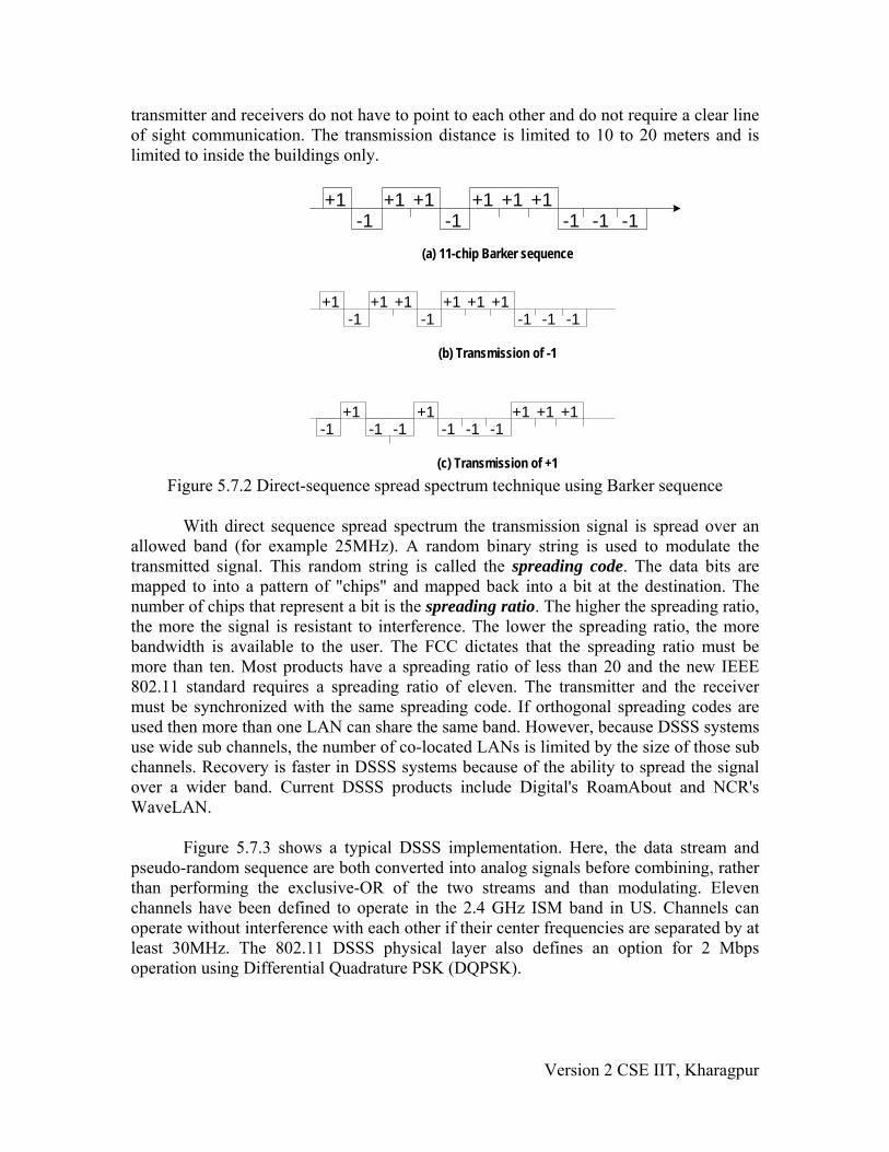
transmitter and receivers do not have to point to each other and do not require a clear line of sight communication. The transmission distance is limited to 10 to 20 meters and is limited to inside the buildings only.
Figure 5.7.2 Direct-sequence spread spectrum technique using Barker sequence
With direct sequence spread spectrum the transmission signal is spread over an allowed band (for example 25MHz). A random binary string is used to modulate the transmitted signal. This random string is called the spreading code. The data bits are mapped to into a pattern of "chips" and mapped back into a bit at the destination. The number of chips that represent a bit is the spreading ratio. The higher the spreading ratio, the more the signal is resistant to interference. The lower the spreading ratio, the more bandwidth is available to the user. The FCC dictates that the spreading ratio must be more than ten. Most products have a spreading ratio of less than 20 and the new IEEE 802.11 standard requires a spreading ratio of eleven. The transmitter and the receiver must be synchronized with the same spreading code. If orthogonal spreading codes are used then more than one LAN can share the same band. However, because DSSS systems use wide sub channels, the number of co-located LANs is limited by the size of those sub channels. Recovery is faster in DSSS systems because of the ability to spread the signal over a wider band. Current DSSS products include Digital's RoamAbout and NCR's WaveLAN.
Figure 5.7.3 shows a typical DSSS implementation. Here, the data stream and pseudo-random sequence are both converted into analog signals before combining, rather than performing the exclusive-OR of the two streams and than modulating. Eleven channels have been defined to operate in the 2.4 GHz ISM band in US. Channels can operate without interference with each other if their center frequencies are separated by at least 30MHz. The 802.11 DSSS physical layer also defines an option for 2 Mbps operation using Differential Quadrature PSK (DQPSK).
+1-1
+1 +1-1 -1
+1 +1 +1-1 -1
(a) 11-chip Barker sequence
+1-1
+1 +1-1 -1
+1 +1 +1-1 -1
(b) Transmission of -1
-1 -1 -1+1 +1 +1
-1 -1+1 +1
-1
(c) Transmission of +1
Version 2 CSE IIT, Kharagpur

(a) Transmitter (b) Receiver
Figure 5.7.3 Direct Sequence Spread Spectrum (DSSS) system,
Frequency Hopping Spread Spectrum (FHSS)
The idea behind spread spectrum is to spread the signal over a wider frequency band, so as to make jamming and interception more difficult and to minimize the effect of interference from other devices In FH it is done by transmitting the signal over a random sequence of frequencies; that is, first transmitting at one frequency, then second, then a third and so on. The random sequence of frequencies is generated with the help of a pseudorandom number generator. As both the receiver and sender use the same algorithm to generate random sequence, both the devices hop frequencies in a synchronous manner and frames transmitted by the sender are received correctly by the receiver. This is somewhat similar to sending different parts of one song over several FM channels. Eavesdroppers hear only unintelligible blips and any attempt to jam the signal results in damaging a few bits only.
Typical block diagram of a frequency-hopping system is shown in Figure 5.7.4. As shown in Figure 5.7.4(a) the digital data is first encoded to analog signal, such as frequency-shift keying (FSK) or Binary-phase shift keying (BPSK). At any particular instant, a carrier frequency is selected by the pseudo-random sequence. The carrier frequency is modulated by the encoder output a then transmitted after band pass filtering At the receiving end, the spread-spectrum signal is demodulated using the same sequence of carrier frequencies generated with the help of same pseudo-random sequence in synchronization with the transmitter, and the demodulated signal filtered using a band-pass filter before decoding as shown in Fig. 5.7.4(b).
Version 2 CSE IIT, Kharagpur

This technique splits the band into many small sub channels (each of 1MHz). The signal then hops from sub channel to sub channel transmitting short bursts of data on each channel for a set period of time, called dwell time. The hopping sequence must be synchronized at the sender and the receiver or information is lost.
The 802.11 frequency hopping physical layer uses 79 non-overlapping 1 MHz
Channels to transmit 1 Mbps data signal over 2.4 GHz ISM band. There is option to transmit at the rate of 2 Mbps. A channel hop occurs every 224 μsec. The standard defines 78 hopping patterns that are divided into three sets of 26 patterns each. Each hopping pattern jumps a minimum of six channels in each hop and the hopping sequences are derived via a simple modulo 79 calculation. The hopping patterns from each set collide three times on the average and five times in the worst case over a hopping cycle. Each 802.11 network must use a particular hopping pattern. The hopping patterns allow up to 26 networks to be collocated and still operate simultaneously.
Figure 5.7.4 Frequency Hopping system, (a) Transmitter (b) Receiver
This feature gives FH systems a high degree of security. In order to jam a frequency hopping system the whole band must be jammed. These features are very attractive to agencies involved with law enforcement or the military. Many FHSS LANs can be co-located if an orthogonal hopping sequence is used. Because the sub channels are smaller than in DSSS, the number of co-located LANs can be greater with FHSS systems. Most new products in wireless LAN technology are currently being developed
Version 2 CSE IIT, Kharagpur

with FHSS technology. Some examples are WaveAccess's Jaguar, Proxim RangeLAN2, and BreezeCom's BreezeNet Pro.
Multipath Interference
Interference caused by signals bouncing off of walls and other barriers and arriving at the receiver at different times is called multipath interference. Multipath interference affects IR, RF, and MW systems. FHSS inherently solves the multipath problem by simply hopping to other frequencies. Other systems use anti-multipath algorithms to avoid this interference. A subset of multipath is Rayleigh fading. This occurs when the difference in path length is arriving from different directions and is a multiple of half the wavelength. Rayleigh fading has the effect of completely cancelling out the signal. IR systems are not affected by Rayleigh fading, because the wavelengths used in IR are very small.
5.7.3 Topology Each computer, mobile, portable or fixed, is referred to as a station in 802.11. The difference between a portable and mobile station is that a portable station moves from point to point but is only used at a fixed point. Mobile stations access the LAN during movement. Fundamental to the IEEE 802.11 architecture is the concept of Basic Service Set (BSS) or wireless LAN cell. A BSS is defined as a group of stations that coordinate their access to the medium under a given instance of medium access control. The geographic area covered by a BSS is known as the Basic Service Area (BSA), which is very similar to a cell in a cellular communication network. All stations with in a BSA with tens of meters in diameter may communicate with each other directly. The 802.11 standard support the formation of two distinct types of BSSs: ad hoc network and Infrastructure BSS.
Two or more BSS's are interconnected using a Distribution System or DS. This concept of DS increases network coverage. Each BSS becomes a component of an extended, larger network. Entry to the DS is accomplished with the use of Access Points (AP). An access point is a station, thus addressable. So data moves between the BSS and the DS with the help of these access points.
Creating large and complex networks using BSS's and DS's leads us to the next
level of hierarchy, the Extended Service Set or ESS. The beauty of the ESS is the entire network looks like an independent basic service set to the Logical Link Control layer (LLC). This means that stations within the ESS can communicate or even move between BSS's transparently to the LLC.
The first type of BSS is known as ad hoc network, which consists of a group of
stations within the range of each other. As its name implies, ad hoc networks are temporary in nature, which are typically created and maintained as needed without prior administrative arrangement. Ad hoc networks can be formed anywhere spontaneously and can be disbanded after a limited period of time. A typical ad hoc network is shown in Figure 5.7.5(a).
Version 2 CSE IIT, Kharagpur

The second type of BSS is known as infrastructure BSS (IBSS), which is
commonly used in practice. An ESS is shown in Fig. 5.7.6 Here, several BSSs are interconnected by a distribution system to form an extended service set (ESS) as shown in Fig. 5.7.5(b). The BSSs are like cells in a cellular communications network. Each BSS is provided with an Access point (AP) that has station functionality and provides access to the distribution system. APs operate on a fixed channel and remain stationary like base stations in a cellular communication system. APs are located such that the BSSs they serve overlap slightly to provide continuous service to all the stations.
(a) (b)
Figure 5.7.5 (a) Basic Service set (BSS), (b) Infrastructure BSS (ESS)
Figure 5.7.6 Extended service set (ESS) An ESS can also provide gateway access for wireless users into a wired network. Each end station associates itself with one access point. Figure 5.7.6 shows three BSSs interconnected through three APs to a distribution system. If station A associated with AP-1 wants to send a frame to another station associated with AP-2, the first sends a frame to its access point (AP-1), which forwards the frame across the distribution system
Version 2 CSE IIT, Kharagpur

to the access point AP-2. AP-2 finally delivers it to the destination station. For forwarding frames across the APs, bridging protocol may be used, which is beyond the scope of IEEE 802.11 standard. However, the 802.11 standard specifies how stations select their access points. The technique used for this purpose is known as scanning, which involves the following steps:
• A station sends a probe frame. • All APs within reach reply with a probe response frame. • The station selects one of the access points, and sends the AP an Association
Request frame. • The AP replies with an Association Response frame. The above protocol is used when a station joins a network or when it wants to
discontinue association with the existing AP because of weakened signal strength or some other reason. The discontinuation of association takes place whenever a station acquires a new AP and the new AP announces it in step 4 mentioned above. For example, assume that station B is moving away from the BSS of AP-1 towards the BSS of AP-2. As it moves closer to the BSS of AP-2, it sends probe frames, which is responded eventually by AP-2. As some of point of time station B prefers AP-2 over AP-1 and associates itself with the access point AP-2. The above mechanism is known as active scanning, as the node is actively searching for an access point. An access point also periodically sends Beacon frame that advertises the capabilities of the access point. In response, a station can associate to the AP simply by sending it an Association request frame. This is known as passive scanning. 5.7.4 Medium Access Control Most wired LANs products use Carrier Sense Multiple Access with Collision Detection (CSMA/CD) as the MAC protocol. Carrier Sense means that the station will listen before it transmits. If there is already someone transmitting, then the station waits and tries again later. If no one is transmitting then the station goes ahead and sends what it has. But when more than one station tries to transmit, the transmissions will collide and the information will be lost. This is where Collision Detection comes into play. The station will listen to ensure that its transmission made it to the destination without collisions. If a collision occurred then the stations wait and try again later. The time the station waits is determined by the back off algorithm. This technique works great for wired LANs but wireless topologies can create a problem for CSMA/CD. However, the wireless medium presents some unique challenges not present in wired LANs that must be dealt with by the MAC used for IEEE 802.11. Some of the challenges are:
• The wireless LAN is prone to more interference and is less reliable. • The wireless LAN is susceptible to unwanted interception leading to security
problems. • There are so called hidden station and exposed station problems.
Version 2 CSE IIT, Kharagpur

In the discussion of both the problem, we shall assume that all radio transmitters have fixed range. When the receiver is in the range of two active transmitters then the signal will be garbled. It is important to note that not all stations are in range of two transmitters. The Hidden Station Problem Consider a situation when A is transmitting to B, as depicted in the Fig. 5.7.7. If C senses the media, it will not hear anything because it is out of range, and thus will falsely conclude that no transmission is going on and will start transmit to B. the transmission will interfere at B, wiping out the frame from A. The problem of a station not been able to detect a potential competitor for the medium because the competitor is too far away is referred as Hidden Station Problem. As in the described scenario C act as a hidden station to A, which is also competing for the medium.
Error!
Figure 5.7.7 Hidden Station Problem
Exposed Station problem Now consider a different situation where B is transmitting to A, and C sense the medium and detects the ongoing transmission between B and A. C falsely conclude that it can not transmit to D, when the fact is that such transmission would cause on problem. A transmission could cause a problem only when the destination is in zone between B and C. This problem is referred as Exposed station Problem. In this scenario as B is exposed to C, that’s why C assumes it cannot transmit to D. So this problem is known as Exposed station problem (i.e. problem caused due to exposing of a station). The problem here is that before transmission, a station really wants to know that whether or not there is any activity around the receiver. CSMA merely tells whether or not there is any activity around the station sensing the carrier.
Version 2 CSE IIT, Kharagpur

5.7.5 Carrier Sense Multiple Access with Collision Avoidance (CSMA-CA)
The solution to these problems is Carrier Sense Multiple Access with Collision Avoidance or CSMA/CA as shown in Fig. 5.7.8.
Main steps can be summarized as:
• Sender sends a short frame called Request to send RTS (20bytes) to the destination. RTS also contains the length of the data frame.
• Destination station responds with a short (14 bytes) clear to send (CTS) frame. • After receiving the CTS, the sender starts sending the data frame. • If collision occurs, CTS frame is not received within a certain period of time.
CSMA/CA works as follows: the station listens before it sends. If someone is already transmitting, wait for a random period and try again. If no one is transmitting then it sends a short message. This message is called the Ready To Send message (RTS). This message contains the destination address and the duration of the transmission. Other stations now know that they must wait that long before they can transmit. The destination then sends a short message, which is the Clear To Send message (CTS). This message tells the source that it can send without fear of collisions. Each packet is acknowledged. If an acknowledgement is not received, the MAC layer retransmits the data. This entire sequence is called the 4-way handshake protocol.
Figure 5.7.8 Four-Way handshake protocol
Carrier Sensing In IEEE 802.11, carrier sensing is performed in two levels known as physical carrier sensing and virtual carrier sensing. Physical carrier sensing is performed at the radio interface by sensing the presence of other IEEE 802.11 stations by analyzing all detected packets and relative strength from other sources. Virtual carrier sensing is used by a source station to inform all other stations in the BSS about the length of the data frame that it intends to send. The headers of the RTS and CTS control frames contain the duration field (in μsec). Stations detecting a duration field adjust their Network Allocation Vector (NAV), which indicates the duration the station must wait before channel can be sampled again for sensing status of the medium. The protocol may be considered as a 4-way handshake protocol is shown in Figure 6.39.
Version 2 CSE IIT, Kharagpur

The above protocol known as Multiple Access Carrier Avoidance (MACA) was subsequently extended to improve its performance and the new protocol, with the following three additions, was renamed as MACAW. First, the receiver sends an ACK frame after receiving a frame and all stations must wait for this ACK frame before trying to transmit. Second, the back-off algorithm is to run separately for each data stream, rather than for each station. This change improves the fairness of the protocol. Finally, some mechanism was added for stations to exchange information about configuration, and way to make the back-off algorithm react less violently to temporary problem.
The IEEE 802.11 protocol is specified in terms of coordination function that
determine when a station in a BSS is allowed to transmit and when it may be able to receive data over the wireless medium. The distributed coordination function (DCF) provides support for asynchronous data transfer on a best-effort basis. Four following types of inter frame spaces (IFSs) are used:
• Short IFS (SIFS): This is the period between the completion of packet transmission
and the start of ACK frame. • Point coordination IFS (PIFS): This is SIFS plus a slot time. • Distributed IFS (DIFS): This PIFS Plus a slot time. • Extended IFS (EIFS): This is longer than IFS used by a station that has received a
packet that it could not understand. This is needed to prevent collisions. The sequence of events that take place at the source, destination and other stations is shown in Figure 5.7.9.
DIFS
Figure 5.7.9 CSMA/CA Back-off algorithm timing sequence
FRAME
ACK
NEXT FRAME •DIFS
DEFER ACCESS Back-off after defer
SIFS
DIFS
SOURCE
Others
Contention window
DESTINATION
Version 2 CSE IIT, Kharagpur

5.7.6 Framing The frame format of the IEEE 802.11 is shown in Figure 5.7.10(a). The frames can be categorized into three types; management frame, control frame and data frame. The management frames are used for association and disassociation of stations with at the AP, authentication and de-authentication, and timing and synchronization. The detailed Frame Format is shown in Fig. 5.7.10.
Framecontrol
Destination /ID
Addr.1
Addr.2
Addr.3
SequenceControl
Addr.4
Framebody
CRC2 2 6 6 6 2 6 0-2312 4
Protocolversion
Type RetryToDS
MoreFrag
Subtype Pwr.mgt.
Moredata
WEP Rsvd
ToDS
FromDS
Addr.1
Addr.2
Addr.3
Addr.4
Meaning
Data from station tostation within a BSS
Data frame existing inDS
Data frame destinedfor the DS
WDS frame beingdistributed from AP to AP
0
0
1
1
0
1
0
1
Desti.Addr.
Desti.Addr.
BSSID
ReceiverAddr.
SourceAddr.
BSSID
SourceAddr.
TransAddr.
BSSID
SourceAddr.
Desti.Addr.
Desti.Addr.
N/A
N/A
N/A
SourceAddr.
FromDS
MAC HEADER
(a)
(b)
(c) Figure 5.7.10 Frame format for 802.11
Version 2 CSE IIT, Kharagpur
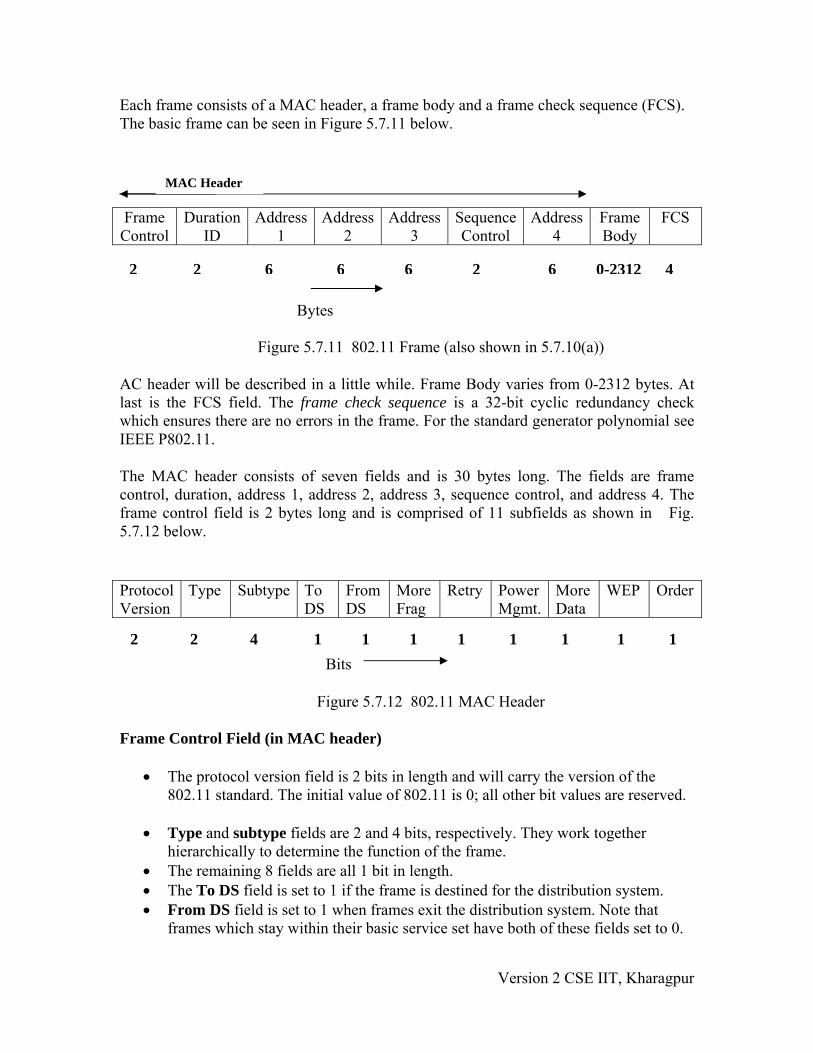
Each frame consists of a MAC header, a frame body and a frame check sequence (FCS). The basic frame can be seen in Figure 5.7.11 below.
Figure 5.7.11 802.11 Frame (also shown in 5.7.10(a))
AC header will be described in a little while. Frame Body varies from 0-2312 bytes. At last is the FCS field. The frame check sequence is a 32-bit cyclic redundancy check which ensures there are no errors in the frame. For the standard generator polynomial see IEEE P802.11.
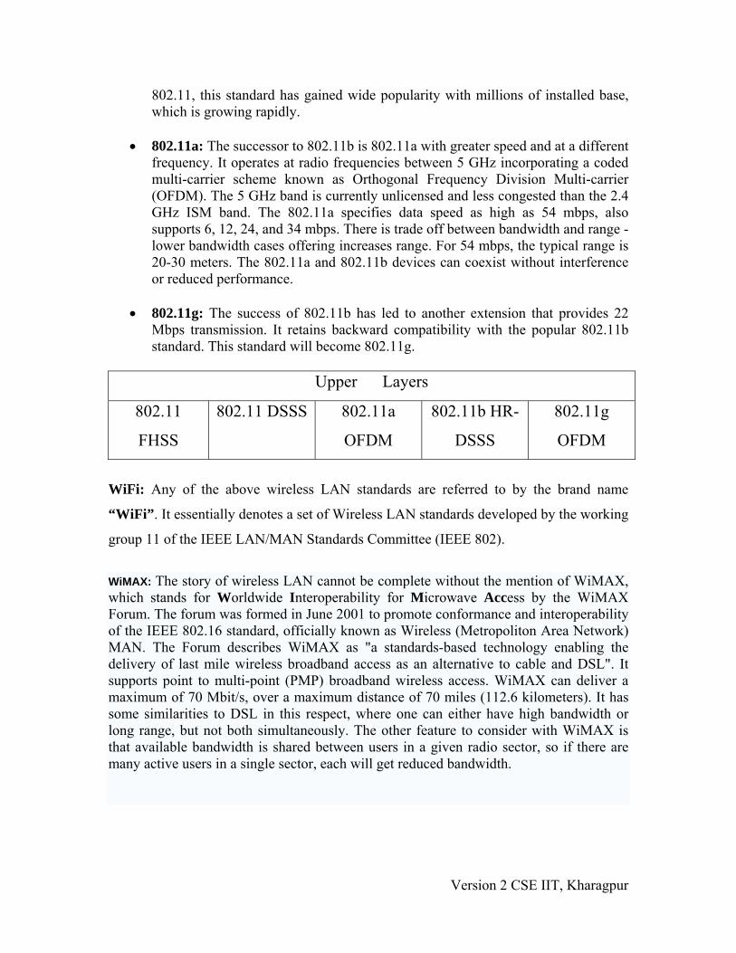
The MAC header consists of seven fields and is 30 bytes long. The fields are frame control, duration, address 1, address 2, address 3, sequence control, and address 4. The frame control field is 2 bytes long and is comprised of 11 subfields as shown in Fig. 5.7.12 below.
Figure 5.7.12 802.11 MAC Header Frame Control Field (in MAC header)
• The protocol version field is 2 bits in length and will carry the version of the 802.11 standard. The initial value of 802.11 is 0; all other bit values are reserved.
• Type and subtype fields are 2 and 4 bits, respectively. They work together hierarchically to determine the function of the frame.
• The remaining 8 fields are all 1 bit in length. • The To DS field is set to 1 if the frame is destined for the distribution system. • From DS field is set to 1 when frames exit the distribution system. Note that
frames which stay within their basic service set have both of these fields set to 0.
Frame Control
Duration ID
Address 1
Address 2
Address 3
Sequence Control
Address 4
Frame Body
FCS
Protocol Version
Type Subtype To DS
From DS
More Frag
Retry Power Mgmt.
More Data
WEP Order
2 2 6 6 6 2 6
MAC Header
0-2312 4
Bytes
2 2 4 1 1 1 1 1 1 1 1 Bits
Version 2 CSE IIT, Kharagpur

• The More Frag field is set to 1 if there is a following fragment of the current MSDU.
• Retry is set to 1 if this frame is a retransmission. • Power Management field indicates if a station is in power save mode (set to 1)
or active (set to 0). • More data field is set to 1 if there is any MSDUs are buffered for that station. • The WEP field is set to 1 if the information in the frame body was processed with
the WEP algorithm. • The Order field is set to 1 if the frames must be strictly ordered. • The Duration/ID field is 2 bytes long. It contains the data on the duration value
for each field and for control frames it carries the associated identity of the transmitting station.
• The address fields identify the basic service set, the destination address, the source address, and the receiver and transmitter addresses. Each address field is 6 bytes long.
• The sequence control field is 2 bytes and is split into 2 subfields, fragment number and sequence number.
• Fragment number is 4 bits and tells how many fragments the MSDU is broken into.
• The sequence number field is 12 bits that indicates the sequence number of the MSDU. The frame body is a variable length field from 0 - 2312. This is the payload.
5.7.7 Security Wireless LANs are subjected to possible breaches from unwanted monitoring. To overcome this problem, IEEE 802.11 specifies an optional MAC layer security system known as Wired Equivalent Privacy (WEP). The objective is to provide a level of privacy to the wireless LAN similar to that enjoyed by wired Ethernets. It is achieved with the help of a 40-bit shared key authentication service. By default each BSS supports up to four 40-bit keys that are shared by all the clients in the BSS. Keys unique to a pair of communicating clients and direction of transmission may also be used. Advanced Encryption Standard (AES) (802.11i) for authentication and encryption is recommended as a long-term solution. 5.7.8 IEEE 802.11 extensions As the first standard was wrapping up, the creation of a new standards activity begun in the 802.11 standards body. The new activity gave rise to two more standards; IEEE 802.11 b and IEEE 802.11a.
• 802.11b: This standard was developed by IEEE with the support from the consortium Wireless Ethernet Compatibility Alliance (WECA). This standard is backward compatible with the original standard that added two new data rates 5.5 mbps and 11 Mbps using two coding techniques; the mandatory coding mode known as Complementary Coding Keying (CCK) modulation and Packet Binary Convolution Coding (PBCC). Because of backward compatibility with the
Version 2 CSE IIT, Kharagpur
802.11, this standard has gained wide popularity with millions of installed base, which is growing rapidly.
• 802.11a: The successor to 802.11b is 802.11a with greater speed and at a different
frequency. It operates at radio frequencies between 5 GHz incorporating a coded multi-carrier scheme known as Orthogonal Frequency Division Multi-carrier (OFDM). The 5 GHz band is currently unlicensed and less congested than the 2.4 GHz ISM band. The 802.11a specifies data speed as high as 54 mbps, also supports 6, 12, 24, and 34 mbps. There is trade off between bandwidth and range - lower bandwidth cases offering increases range. For 54 mbps, the typical range is 20-30 meters. The 802.11a and 802.11b devices can coexist without interference or reduced performance.
• 802.11g: The success of 802.11b has led to another extension that provides 22
Mbps transmission. It retains backward compatibility with the popular 802.11b standard. This standard will become 802.11g.
Upper Layers
802.11
FHSS
802.11 DSSS 802.11a
OFDM
802.11b HR-
DSSS
802.11g
OFDM
WiFi: Any of the above wireless LAN standards are referred to by the brand name
“WiFi”. It essentially denotes a set of Wireless LAN standards developed by the working
group 11 of the IEEE LAN/MAN Standards Committee (IEEE 802).
WiMAX: The story of wireless LAN cannot be complete without the mention of WiMAX, which stands for Worldwide Interoperability for Microwave Access by the WiMAX Forum. The forum was formed in June 2001 to promote conformance and interoperability of the IEEE 802.16 standard, officially known as Wireless (Metropoliton Area Network) MAN. The Forum describes WiMAX as "a standards-based technology enabling the delivery of last mile wireless broadband access as an alternative to cable and DSL". It supports point to multi-point (PMP) broadband wireless access. WiMAX can deliver a maximum of 70 Mbit/s, over a maximum distance of 70 miles (112.6 kilometers). It has some similarities to DSL in this respect, where one can either have high bandwidth or long range, but not both simultaneously. The other feature to consider with WiMAX is that available bandwidth is shared between users in a given radio sector, so if there are many active users in a single sector, each will get reduced bandwidth.
Version 2 CSE IIT, Kharagpur

Fill In The Blanks: 1. Initial cost of wireless LAN can be ____________ than the cost of wired LAN
hardware. 2. Wireless LANs have Lower ___________ due to susceptibility of radio
transmission to noise and _____________. 3. Limited data rate because of the use of ______________ transmission techniques
enforced to ISM band users. 4. The big advantage to Micro wave systems is higher __________ achieved
because they do not have the overhead involved with _________ systems. 5. _______________ is an example of systems with microwave technology. 6. Spread spectrum technology currently comes in two types:
___________________ and ______________. 7. _________________ represents each bit in the frame by multiple bits in the
transmitted frame. 8. In DSSS, a random binary string is used to modulate the transmitted signal. This
random string is called the _______________. 9. In DSSS, the data bits are mapped to into a pattern of "chips" and mapped back
into a bit at the destination. The number of chips that represent a bit is the____________.
10. The higher the spreading ratio, the more the signal is ____________ to interference.
11. In Frequency Hoping system, signal hops from sub channel to sub channel transmitting short bursts of data on each channel for a set period of time, called_________.
12. WaveAccess's Jaguar, Proxim RangeLAN2, and BreezeCom's BreezeNet Pro are examples of ____________ technique.
13. A ________ is defined as a group of stations that coordinate their access to the medium under a given instance of medium access control. The geographic area covered by a BSS is known as the ______________.
14. The problem of a station not been able to detect a potential competitor for the medium because the competitor is too far away is referred as ____________.
15. _______________________ is used by a source station to inform all other stations in the BSS about the length of the data frame that it intends to send.
Answers:
1. higher 2. reliability, interference 3. spread spectrum 4. throughput, spread spectrum 5. RadioLAN 6. direct sequence spread spectrum (DSSS), frequency hopping spread spectrum
(FHSS). 7. Direct Sequence Spread Spectrum (DSSS) 8. spreading code
Version 2 CSE IIT, Kharagpur
9. spreading ratio 10. resistant 11. dwell time 12. frequency hopping spread spectrum (FHSS). 13. BSS (basic service set) , BSA(basic service area) 14. Hidden Station Problem 15. Virtual carrier sensing
Short Questions:
Q-1. What are the reasons for wireless LANs not popular, if we look at recent past and make them popular now? Ans:Until recently wireless version of LANs were not popular because of the following reasons:
• High cost: Previously the equipments cost more. • Low data rate: Initially, the data rate supported by the WLAN is too less, so
it supports only a few applications. • Occupational safety concerns • Licensing requirements
Q-2. State some advantages of Wireless LANs. Ans: Some of the advantages of wireless LANs are mentioned below:
Mobility: An increasing number of LAN users are becoming mobile. These mobile users require that they are connected to the network regardless of where they are because they want simultaneous access to the network.
Installation speed and simplicity: Wireless LANs are very easy to install. There is no requirement for wiring every workstation and every room.
Installation flexibility: If a company moves to a new location, the wireless system is much easier to move than ripping up all of the cables that a wired system would have snaked throughout the building. This also provides portability.
Reduced cost of ownership: While the initial cost of wireless LAN can be higher than the cost of wired LAN hardware, but long term cost benefits are greater in dynamic environment requiring frequent moves and changes.
Scalability: Wireless LAN can be configured in a variety of topologies to meet the users need and can be easily scaled to cover a large area with thousands of users roaming within it.
Q-3. State few disadvantages of wireless LANs. Ans: Some of the limitations and challenges are mentioned below:
Version 2 CSE IIT, Kharagpur
• Lower reliability due to susceptibility of radio transmission to noise and interference.
• Fluctuation of the strength of the received signal through multiple paths causing fading.
• Vulnerable to eavesdropping leading to security problem. • Limited data rate because of the use of spread spectrum transmission techniques
enforced to ISM band users.
Q- 4. Explain in brief the Frequency Hopping Spread Spectrum (FHSS) technique. Ans: The idea behind spread spectrum is to spread the signal over a wider frequency band, so as to make jamming and interception more difficult and to minimize the effect of interference from other devices In FH it is done by transmitting the signal over a random sequence of frequencies; that is, first transmitting at one frequency, then second, then a third and so on. The random sequence of frequencies is generated with the help of a pseudorandom number generator. Q-5. Explain multi-path interference and a solution to it in brief. Ans: Interference caused by signals bouncing off of walls and other barriers and arriving at the receiver at different times is called multipath interference. Multipath interference affects IR, RF, and MW systems. FHSS inherently solves the multipath problem by simply hopping to other frequencies. Other systems use anti-multipath algorithms to avoid this interference. A subset of multipath is Rayleigh fading. This occurs when the difference in path length is arriving from different directions and is a multiple of half the wavelength. Q-6. Explain Exposed station problem in brief. Ans: Consider a situation where B is transmitting to A, and C sense the medium and detects the ongoing transmission between B and A. C falsely conclude that it can not transmit to D, when the fact is that such transmission would cause on problem. A transmission could cause a problem only when the destination is in zone between B and C. This problem is referred as Exposed station Problem. In this scenario as B is exposed to C, that’s why C cannot transmit to D. So this problem is known as Exposed station problem (i.e. problem caused due to exposing of a station). The problem here is that before transmission, a station really wants to know that whether or not there is any activity around the receiver. CSMA merely tells whether or not there is any activity around the station sensing the carrier.
Version 2 CSE IIT, Kharagpur